Article

Assessment of Thermal Management Using a Phase-Change Material Heat Sink under Cyclic Thermal Loads

1
Key Lab of Modern Manufacture Quality Engineering, Hubei University of Technology, Wuhan 430068, China
2
Centre for Hydrogen & Renewable Energy, Central Queensland University, Gladstone 3043, Australia
3
School of Aerospace, Mechanical and Mechatronic Engineering, The University of Sydney, Sydney 2006, Australia
*
Authors to whom correspondence should be addressed.
Energies 2024, 17(19), 4888; https://doi.org/10.3390/en17194888
Submission received: 27 August 2024 / Revised: 14 September 2024 / Accepted: 26 September 2024 / Published: 29 September 2024
(This article belongs to the Special Issue Thermal Energy Storage Systems Modeling and Experimentation)

Abstract

:
Phase-change materials (PCMs) are widely used in the thermal management of electronic devices by effectively lowering the hot end temperature and increasing the energy conversion efficiency. In this article, numerical studies were performed to understand how temperature instability during the periodic utilization of electronic devices affects the heat-dissipation effectiveness of a phase-change material heat sink embedded in an electronic device. Firstly, three amplitudes of 10 °C, 15 °C, and 20 °C for fixed periods of time, namely, 10 min, 20 min, and 40 min, respectively, were performed to investigate the specific effect of amplitude on the PCM melting rate. Next, the amplitude was fixed, and the impact of the period on heat sink performance was evaluated. The results indicate that under the 40 min time period, the averaged melting rate of PCMs with amplitudes of 20 °C, 15 °C, and 10 °C reaches the highest at 19 min, which saves 14 min, 10 min, and 8 min, respectively, compared with the constant input of the same melting rate. At a fixed amplitude of 20 °C, the PCM with a period of 40 min, 20 min, and 10 min has the highest averaged melting rate at 6 min, 11 min, and 19 min, saving the heat dissipation time of 3 min, 8 min, and 14 min, respectively. Overall, it was observed that under identical amplitude conditions, the peak melting rate remains consistent, with longer periods resulting in a longer promotion of melting. On the other hand, under similar conditions, larger amplitude values result in faster melting rates. This is attributed to the fact that the period increases the heat flux output by extending the temperature rise, while the amplitude affects the heat flux by adjusting the temperature.

1. Introduction

The world is transforming toward a more digital and renewable future owing to advancements in electrochemical storage, such as lithium-ion batteries, in terms of specific energy, durability, and reliability. As a result, emerging compact and lighter designs for electronic devices (EDs) [1] are conceived, leading to ever-increasing and intensified heat loads. Moreover, the maturity of electrochemical devices has also stimulated transportation electrification, especially in the aerospace sector, where cyclic thermal loads are presented due to the dynamic operating conditions [2,3]. Therefore, thermal management systems (TMSs) should be well-designed to tackle these thermal hazards; otherwise, the durability and safety of these electrochemical devices will be greatly undermined [4]. In EDs [3], about 55% of failures and damages are reported to be temperature-induced. Phase-change materials (PCMs) are widely used in TMSs for EDs [4,5,6,7,8] and batteries due to their high latent heat of fusion and minimal temperature variation during operations [9]. Related studies have demonstrated the superior performance of the PCM-based TMS in maintaining EDs operating within their optimum temperature range [10]. However, the low thermal conductivity of PCMs lowers the thermal powers of the TMS, thereby requiring a heat transfer enhancement for melting (and sometimes solidification) processes. Adding materials [11,12,13] with high thermal conductivities in the form of porous media [14,15], fins [16,17,18,19], and novel periodic structures [20,21,22,23] to the PCMs are widely adopted to extend the heat-exchange surfaces, thus improving thermal management performance.
There is a large body of research publications for PCM-based TMSs. E. M. and A. K. Bhagat [24] experimentally studied the application of flexible phase-change materials (FPCMs) in compact electronic equipment, especially their thermal management effects in LED bulbs, and obtained the influence of different FPCM compositions on temperature control. De-Xin Zhang et al. [25] studied the thermal control performance of a PCM-based radiator under the transient heat flow impact of electronic equipment through numerical simulation. It was found that the PCM radiator can significantly reduce the maximum temperature compared with traditional radiators, and the thermal control efficiency can be further improved by optimizing the PCM filling mode and equipment placement angle. J. G. Qu et al. [26] studied the melting heat-transfer process of metal foam and carbon foam/PCM composites in electronic equipment temperature control through experiments. It was found that the metal foam can reduce the temperature of the heat source and delay the start time of PCM melting and the emergence of natural convection. In contrast, the anisotropy of the carbon foam leads to its thermal conductivity out of the plane being greater than that in aircraft. In addition, an increase in ambient temperature will reduce the time required to trigger the melting of the carbon foam/PCM composite. However, it will not significantly affect the duration of the melting process. Ahmad F. Turki et al. [27] studied the thermal performance of nano-encapsulated phase-change materials (NEPCMs)—water nanofluids in electronic devices in the presence of a heat source. The free convection heat transfer in a square, enclosed space was simulated using computational fluid dynamics (CFDs), and the effects of different Rayleigh (Ra) numbers, nondimensional melting temperatures, and NEPCM melting intensities on the heat transfer rate, flow patterns, and heat transfer performance were analyzed. It was observed that when the dimensionless melting temperature is 0.3, the heat transfer rate reaches its optimum, and this result is independent of the Ra number. It was concluded that adding NEPCMs to the base fluid can increase the heat transfer efficiency by 12.5%, while an increase in the aspect ratio (AR) at high Ra numbers leads to a 5% increase in the Nusselt (Nu) number. Li et al. [28] studied the thermal performance of needle-fin heat sinks with phase-change materials (PCMs) in electronic device thermal management through experiments and numerical simulations. Their findings concluded that the PCM’s volume fraction significantly impacts the heat sink’s thermal performance under continuous and intermittent operating conditions. Furthermore, the authors noted that in passive cooling mode, a PCM can extend the effective working time of the heat sink; however, in active cooling mode, when a 30% volume fraction PCM is used in combination with a fan, it can reduce the peak temperature and temperature fluctuations of the chip. A further wing diameter and height optimization by the authors revealed that the optimized heat sink structure significantly improves the thermal management efficiency of electronic devices. Imran Zahid et al. [29] have experimentally studied electronic equipment that uses an alumina nanoparticle-reinforced phase-change material (NePCM) to cool the thermal performance of different radiators (including simple radiators, circular-pin fin radiators, and copper foam radiators). The study found that the copper foam radiator performed best in all the tested radiator configurations, especially during the charging process when the set operating temperature was reached. The experimental results indicated that the addition of NePCM and the increase in the concentration of alumina nanoparticles could regulate the heat transfer performance and maintain the system’s basic temperature within the operating range of the electronic devices. However, high concentrations of nanoparticles can lead to a decrease in the heat transfer rate under high heat flow, but the overall heat transfer rate increases at all nanoparticle mass percentages.
The surveyed literature indicates that utilizing the latent heat of a PCM to extend the operating time of electronic devices is effective, but most of the research remains focused on optimizing the materials and parameters of the PCM with isothermal or isoflux boundaries. However, in actual working conditions, the use of electronic devices is mostly periodic, along with periodic heat generation. Therefore, temperature control stability must be considered to address this concern. Secondly, the heat transfer characteristics of PCMs under dynamic thermal boundaries, especially in electronic devices, have hardly been reported in the study of the influence of dynamic heat sources. Only a few studies have investigated PCM heat transfer under dynamic heat sources. S. Mirza et al. [30] proposed a new method to predict the thermal performance of PCM-based heat sinks under periodic heating and developed dimensionless models based on zero-dimensional (0-D) and one-dimensional (1-D) analyses for a wide range of radiator responses to solid, liquid, solid–liquid, or other experiments using a metal-based PCM and monitoring its temperature under sinusoidal varying heat input. By comparing the model predictions with the experimental results in the phase space diagram, it was found that the 0-D model accurately predicted the system response when the Biot number of the radiator was less than 0.1, while the 1-D model predicted more accurately than 87.5% in all cases, including varying the PCM thickness, the external heat transfer coefficient, or the ambient temperature. N. Biswas et al. [31] investigated the effect of uniform and non-uniform (sinusoidal) heating on heat transfer in a square cavity with a moving sidewall and with a porous medium when heated at the bottom. It was found that the non-uniform heating with sinusoidal waveform significantly improved the heat transfer efficiency despite the presence of porous media in the cavity. Through numerical simulation and comparative analysis, the influence of different parameters (such as the Richardson number, Reynolds number, Darcy number, and porosity) on the thermal performance is discussed, and the heat flow behavior, from the heat source to the cold end, is fully described using a heat function and hot wire diagram. R. Djebali et al. [32] investigated the effects of using nanofluid to enhance heat transfer and minimize entropy generation in a microscale high cavity, particularly considering the effects of magnetic field and sinusoidal heating on these processes. The possibility of optimizing these parameters in a microscale thermal management system was assessed by analyzing the effects of different parameters such as nanofluid concentration, magnetic field intensity, and heating mode on heat transfer and entropy generation.
Although many studies have explored the thermal management of electronic devices using PCM [33,34,35,36,37,38,39,40,41,42,43,44,45,46], there remains a gap in understanding the thermal responses of a designed PCM sink under dynamic/cyclic heat loads. To address this gap, we have conducted a study that evaluates both periodic and constant input methods as the boundary conditions for PCM systems, changing the period and amplitude of the periodic input to explore a reasonable input method that can achieve the best heat storage and dissipation effect of the PCM. To summarize, periodic heat generation accompanied by the usage strategies of electronics leads to different PCM-based thermal management system designs, depending on the patterns and periodicity of the thermal inputs. To understand the thermal and melting characteristics of a fixed PCM heat sink under various periodic thermal conditions, a rectangular PCM cavity with uniform, linear, and sinusoidal non-uniform heating on the right side was used, while the other three surfaces were adiabatic. The numerical code was validated against experimental data. The main objective of this work was to evaluate the thermal performance of the two heating strategies on a mutually reasonable basis to determine the preferred heating strategy. Finally, the frequency and amplitude of the variable temperature wall heating were investigated to discover its influence on the heat flow in the PCM melting. By understanding the thermal response of the PCM enclosure concerning the periodicity of the thermal inputs, one could provide an important reference for designing and optimizing PCM-based thermal management systems for practical electronic devices under periodic operation. Therefore, the novelty of the present study is to understand how temperature variation during the periodic utilization of electronic devices affects the heat dissipation efficiency of the PCM. The results of this study may provide new insights into the optimal PCM-based thermal management of electronic devices and will be useful for the future design and optimization of PCM in electronic devices for fluctuating heat sources.

2. Numerical Model

2.1. Physical Model

A rectangular, isothermal PCM-heated enclosure is considered in this study, and the height (H) and length (L) of the enclosure are 60 mm and 25 mm, respectively. The inner PCM is set as lauric acid. The thermal conductivity and melting point of lauric acid are suitable for the optimal operating temperature range of most electronic devices and batteries we are concerned with. As the temperature increases, the lauric acid begins to absorb heat, limiting the temperature rise of such electronic devices. Conversely, when the electronic device is at the right temperature, the action of lauric acid does not have a large negative impact on the heat dissipation of the electronic device. A physical description of the PCM cavity is provided in Figure 1. The thermophysical properties of the PCM are listed in Table 1.

2.2. Governing Equations

For this study, the following assumptions are considered: (1) the motion of the melted PCM is considered to be a Newtonian incompressible laminar flow; (2) the Boussinesq approximation is used to model the buoyancy-induced natural convection; (3) the thermophysical properties of the PCM are temperature-independent, and the PCM properties are dependent on the phase state.
Equations (1)–(3) are the governing equations for mass continuity, x-momentum, and y-momentum conservation that are formulated to describe the convective flow of the melted PCM during melting.
ρ u x + ρ v y = 0
ρ u t + ρ u u x + ρ u v y = P x + x μ u x + y μ u y C 1 γ 2 γ 3 + σ μ
ρ v t + ρ v u x + ρ v v y = P x + x μ v x + y μ v y C 1 γ 2 γ 3 + σ v + ρ g β ( T T m )
In Equations (2) and (3), the final term represents the simulation of the momentum sink through the Carman–Kozeny equation [48]. C denotes the mushy-zone constant linked to the morphology of the mushy zone [49], ranging from 104 to 107 kg/(m3·s). In Section 2.4, the value of the mushy-zone constant is obtained through Zhao’s numerical results [47]. The term σ is a small number (10−3) to prevent division by zero. The liquid phase fraction of the PCM, γ , can be calculated as
γ = 0 ,   T T s ( s o l i d   p h a s e ) ( T T s ) / ( T 1 T s ) , T s < T < T 1 ( m u s h y   z o n e ) 1 , T T 1 ( l i q u i d   p h a s e )
where T S and T 1 are the solidus and liquidus temperatures, respectively.
Heat transfer through PCM is calculated using the enthalpy method:
ρ P C M h t + ρ P C M u h x + ρ P C M v h y = x k P C M T x + y k P C M T y
where the total enthalpy of the PCM material is calculated as the sum of the sensible enthalpy and the latent heat of fusion, that is,
h = h r e f + T r e f T c p d T + γ h s f

2.3. Boundary Conditions

The boundary conditions for the entire enclosure are defined as follows: The right surface is subject to different temperature variations modeled by certain functions, while the remaining three surfaces are adiabatic. A constant temperature boundary condition is used for comparison.
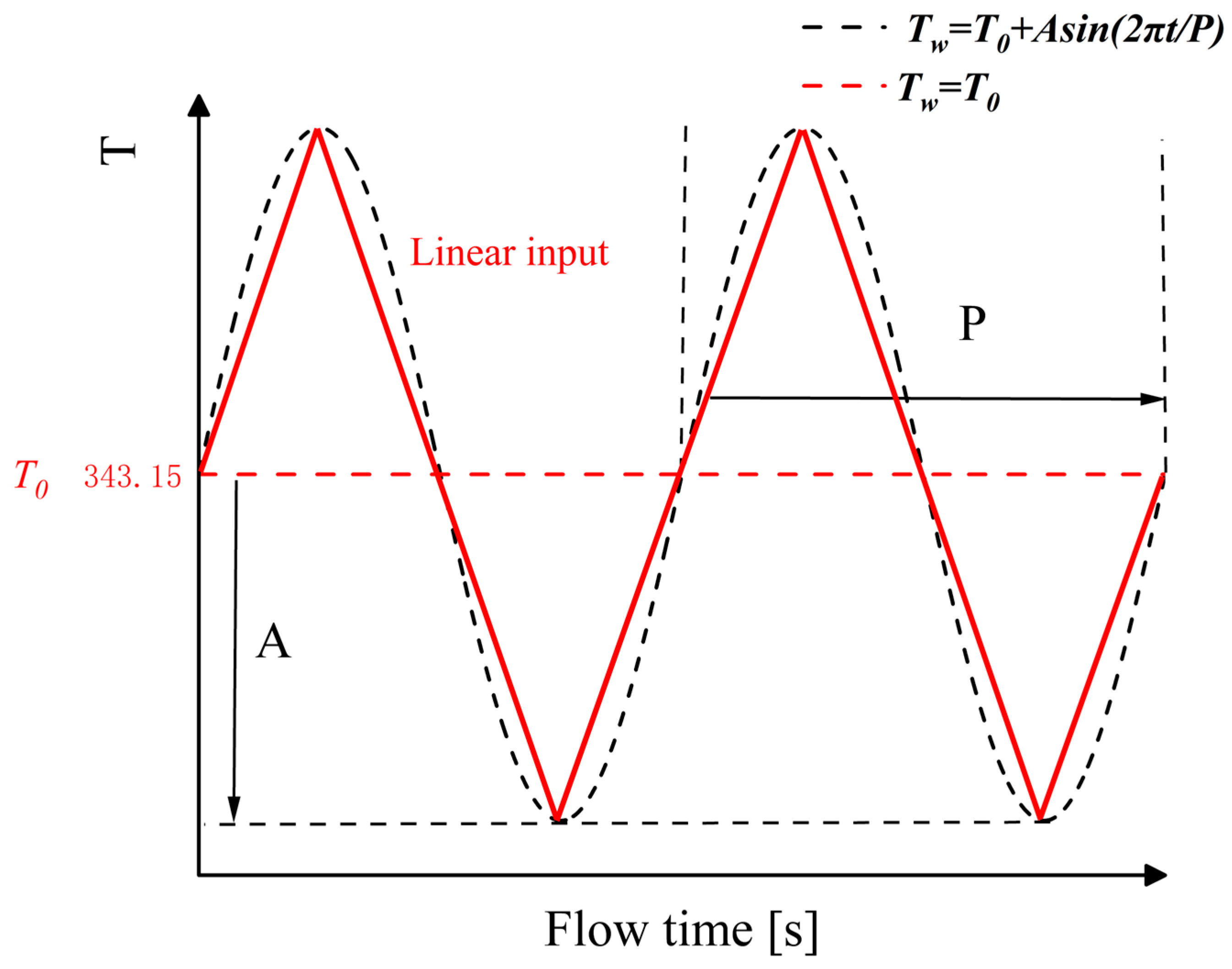
For comparison purposes, the right surface is heated at a constant isothermal temperature (Tw = T0 = 343.15 K). The initial temperature of the right heated surface in the experimental group was 343.15 K, after which the temperature varied according to specified amplitudes and periods. For both types of heating, the temperature description of the right heated surface is expressed in a more general way by using a sine function, as shown below.
T w = T 0  
T w = T 0 + A sin 2 π t / P
where t is the time variable (s); A is the dynamic heat source amplitude (°C) as depicted in Figure 2, and for this study, three values, 10, 15, and 20 °C, are used; and P is the dynamic heat source period (min), which is taken to be 10, 20, and 40 min. On the other hand, T0 is the average temperature at the heat source’s inlet (K), and the average temperature is taken as 343.15 K in this study. Linearly varying boundary conditions share a period and maximum/minimum values with the sine functions, but the variation is linear.
Note that the wall temperature value is chosen based on the experimental results in ref. [47]. The computational domain is initially uniformly set to a temperature of 298.15 K. At the PCM interface, we assume that the temperature and heat flux are continuous. The molten PCM fluid flow is assumed to be in a no-slip state at all walls. For the sake of calculation, like many other experts, we assume that the melted PCM is a Newtonian fluid. For Newtonian fluids, choosing a no-slip boundary condition ensures accuracy while making the calculation process simpler, faster, and easier to modify. This assumption is appropriate in an enclosure and is universally applicable because the thermal cycling of the electronic device in the current case is considered as an input boundary.

2.4. Numerical Strategies

The coupled equations are solved numerically using the commercial computational fluid dynamics (CFD) solver, FLUENT 19.2, based on finite volume approximation. A fully implicit scheme is used for the transient term. For spatial discretization, a second-order-accurate central-differencing scheme is applied to the diffusion terms, while the convection terms are discretized using the QUICK-type scheme. The pressure field is obtained using the PRESTO! (pressure staggering option) interpolation scheme, while the pressure-velocity coupling is handled using the SIMPLE (semi-implicit method for pressure-linked equation) algorithm. The convergence criterion adopts absolute convergence, where the convergence criterion is 1 × 10⁻⁶ for continuity, 1 × 10⁻⁸ for the x-velocity and y-velocity, and 1 × 10⁻¹⁰ for energy.
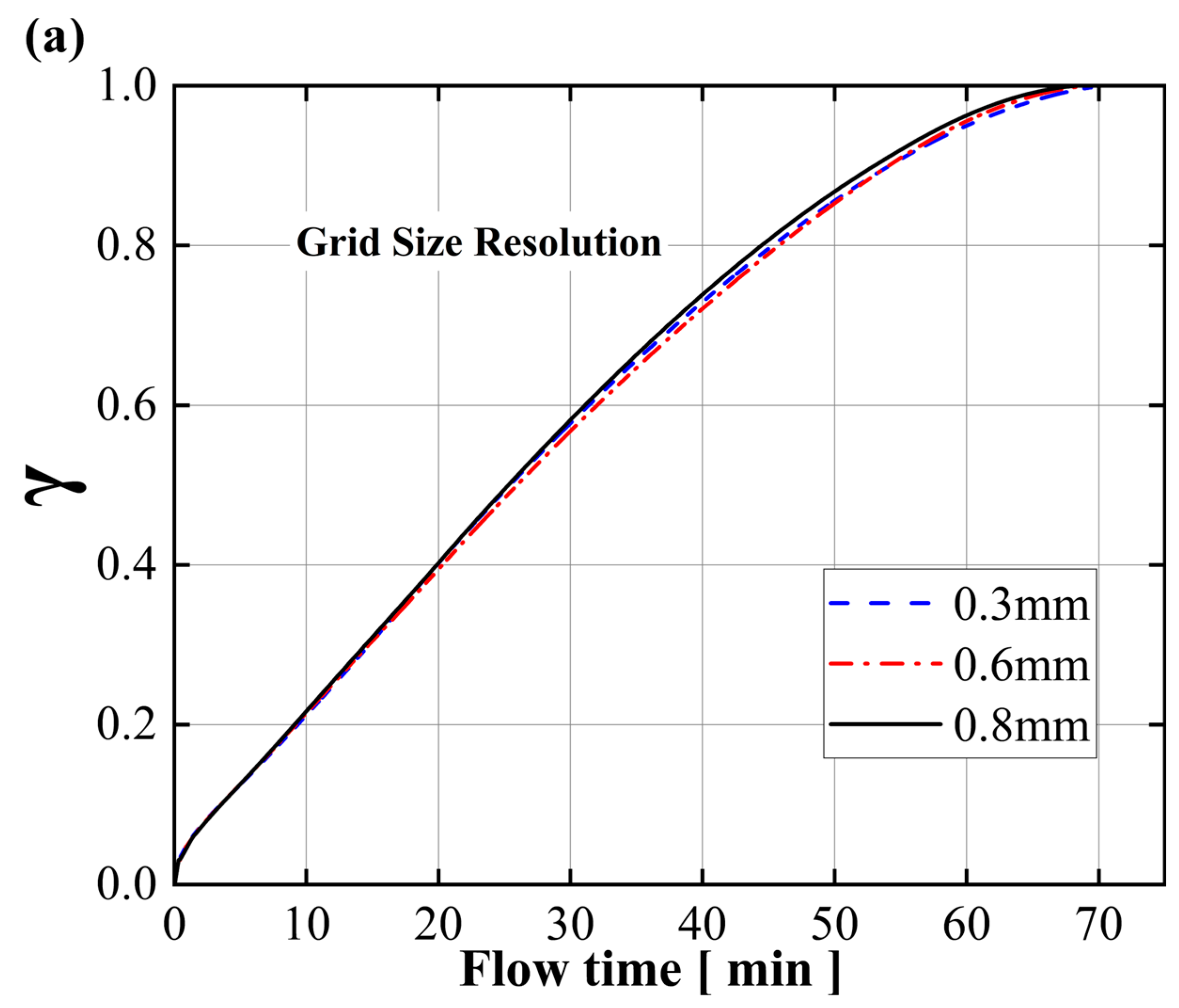
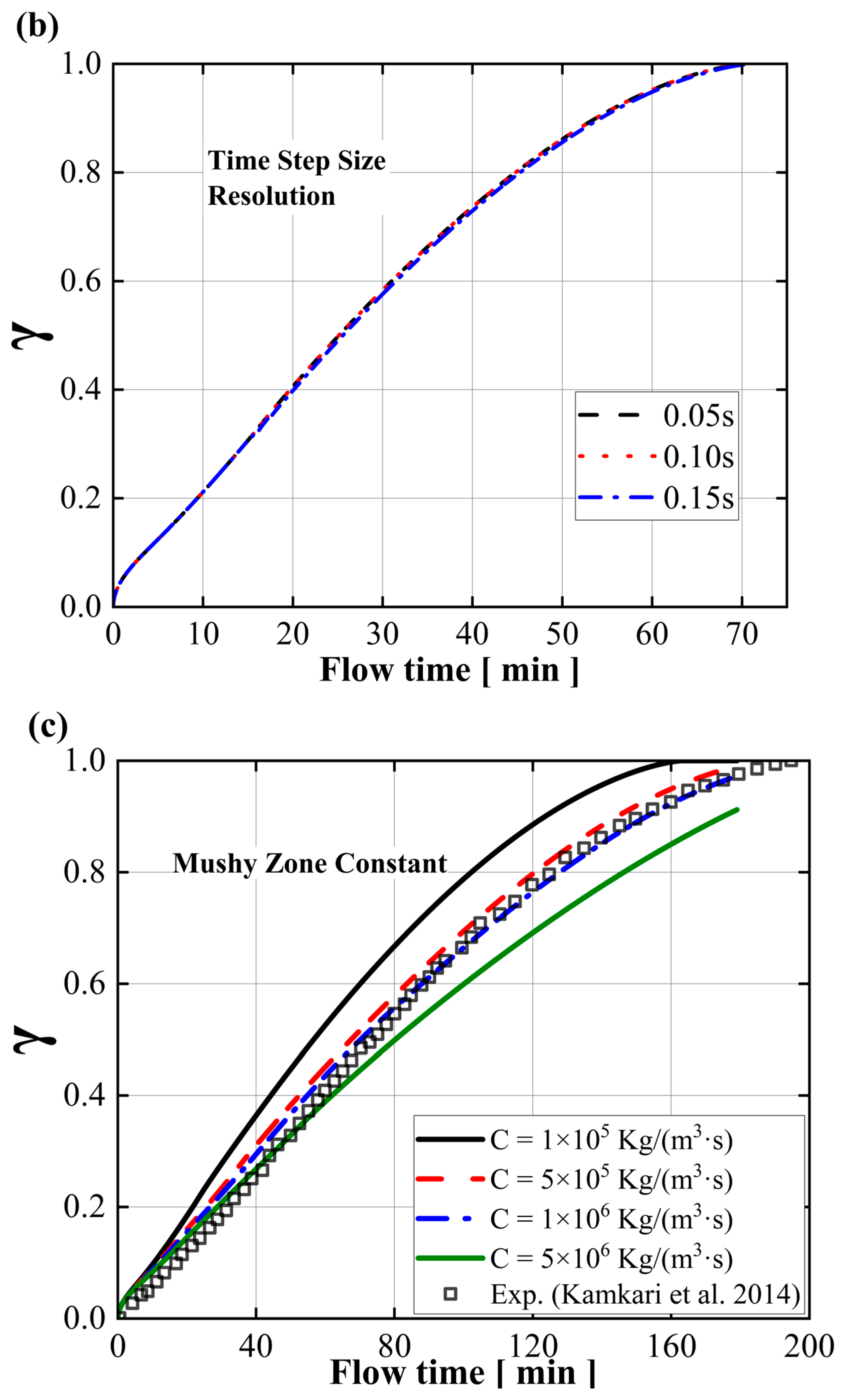
For pure PCM melting within the same enclosure, the independent analysis of the grid step size (0.3 mm, 0.6 mm, and 0.8 mm) and time step size (0.05 s, 0.1 s, and 0.2 s) is carried out as shown in Figure 3a,b. It is worth noting that the three mesh systems, concerning different grid resolutions, have approximately 17,372, 4488, and 2618 numerical elements, respectively. Figure 3a suggests that the grid step size can be acceptable if it is less than 0.6 mm. For all cases in this study, a grid step size of 0.25 mm (24,341 grids) and a time step size of 0.05 s is used. The mesh type used in all cases is an all-quad mesh.
For melting simulations with natural convection, the mushy-zone constant ought to be carefully chosen. According to a numerical study by Zhao et al. [18], which was compared with the experimental measurements in ref. [47], it was concluded that both C = 5 × 10⁵ kg/(m3·s) and C = 1 × 10⁶ kg/(m3·s) are compliant. However, to ensure the accuracy of the numerical results, we compared C = 1 × 10⁵ kg/(m3·s), C = 5 × 10⁵ kg/(m3·s), C = 1 × 10⁶ kg/(m3·s), and C = 5 × 10⁶ kg/(m3·s) with the experiment results for the mushy-zone constant. As shown in Figure 3c, our model is consistent with the experiment results reported in ref. [47]. Therefore, in this study, we consider C = 1 × 10⁶ kg/(m3·s) for the simulation calculation.
For the thermophysical properties of PCM, Yu et al. [50] studied the effects of the thermophysical properties of PCMs on the performance of LTES under stable and fluctuating heat source conditions through sensitivity analysis. It was found that the product of the density and specific heat capacity had the greatest impact on the heat storage capacity under the condition of a stable heat source, while the product of thermal conductivity and specific heat capacity had a more significant effect on the charging rate under the condition of a fluctuating heat source. The changes in these characteristics directly affect the application effect of PCM in LTES systems, in which density and specific heat capacity are the key factors to improve heat storage capacity, and the interaction of thermal conductivity, specific heat capacity, and latent heat has a significant impact on the charging rate. In fact, the sensitivity does have some influence on the final results. However, this paper aims to study a certain PCM thermal management’s performance under different inputs. Due to its complexity, this paper does not consider the effect of PCM’s thermophysical properties or the role of heat transfer. We will consider such factors in our future research.

3. Results and Discussion

For a comprehensive analysis, we simulated three amplitudes (set to A) of 10 °C, 15 °C, and 20 °C for a fixed period (set to P) of time (10 min, 20 min, and 40 min) to investigate the specific effect of amplitude on the PCM melting rate. Then, we fixed the amplitude and evaluated the impact of the period. Additionally, we conducted several non-uniform linear heated surface cases based on a sinusoidal pattern for comparison to derive an optimal heating strategy.

3.1. Comparison of Heating Strategies

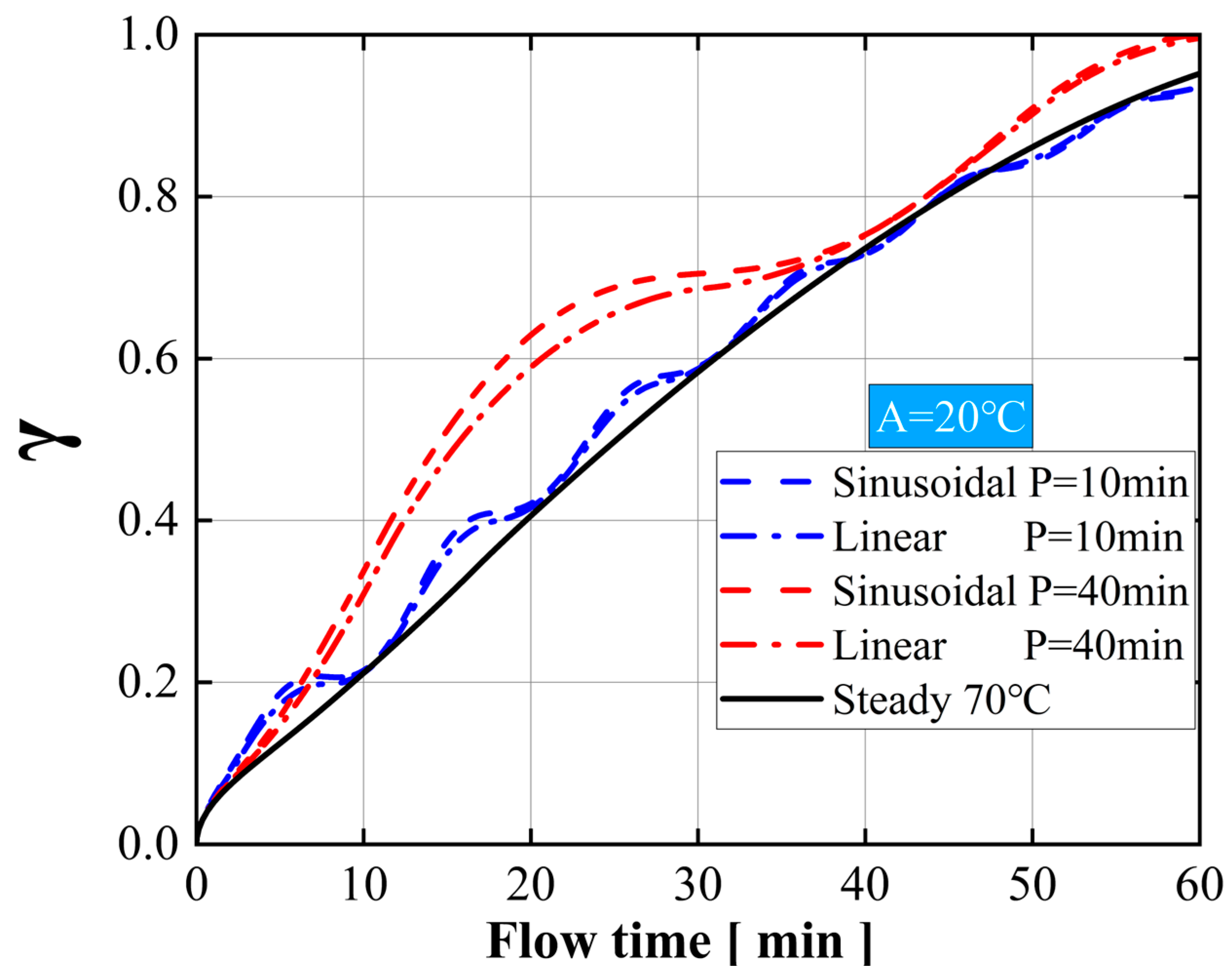
We evaluated three scenarios with a fixed amplitude of 20 °C under different periods (10 min and 40 min). As shown in Figure 4, the sinusoidal input results in a slightly higher melting rate of the PCM than the linear input for the first 40 min at the period of 10 min, and both are higher than the constant input. There is minimal difference between the two for the subsequent 20 min.
When the period is extended to 40 min, sinusoidal input significantly improves the melting rate of the PCM compared with linear input; regardless of the time, sinusoidal input makes the melting rate of PCM always faster than linear input, and both produce much higher melting rates than the constant input. The reason is that the rate of heating with the sinusoidal input is faster than that with the linear input, and the heat flux generated per unit of time is always greater. Increasing the period and increasing the amplitude can amplify the melting effect. Therefore, compared with linear input, a sinusoidal heat source input is a more effective heating method.

3.2. Effect of Sinusoidal Input Amplitude

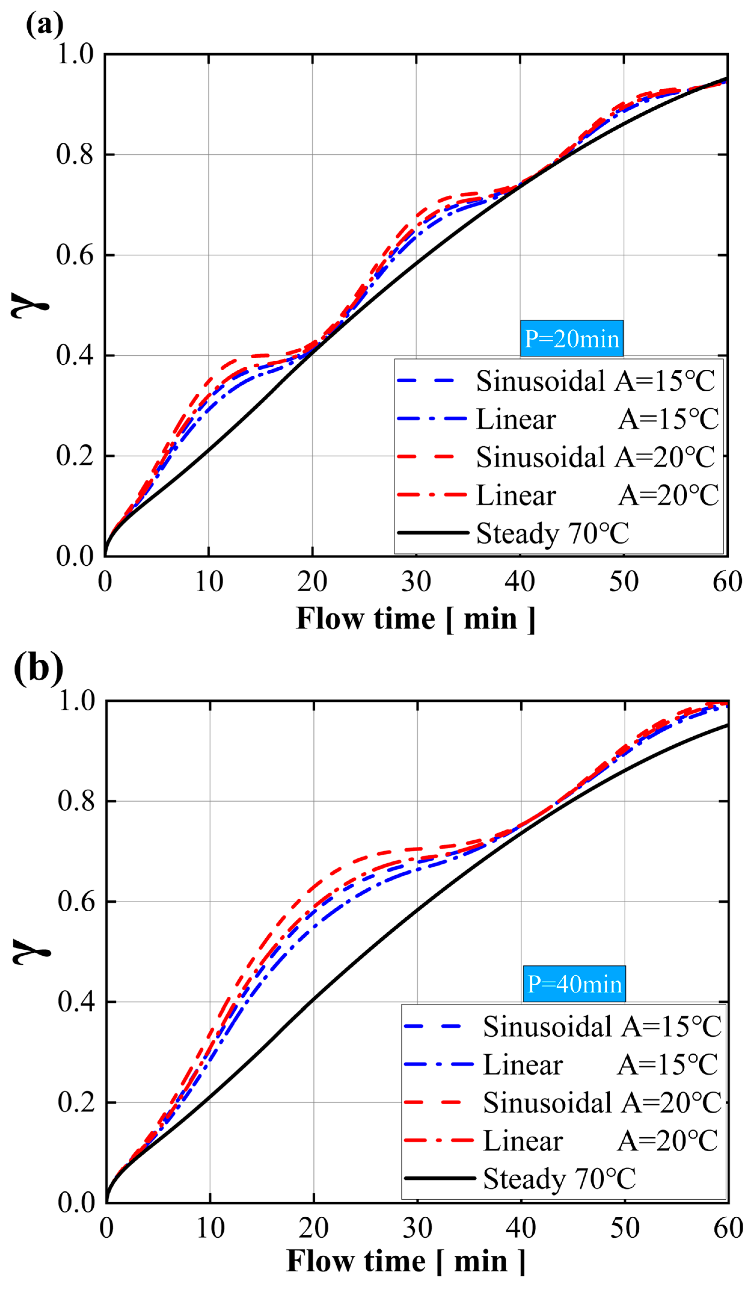
To investigate the effect of the sinusoidal input amplitude, the liquid fractions (set to γ) simulated for different sinusoidal amplitudes (15 °C, 20 °C) at fixed periods of 20 min and 40 min are examined in Figure 5.
With a fixed period, the melting phases of PCM remain consistent across different amplitudes, while the slope of the curve increases significantly with higher amplitudes. With the fixed period growth, the amplitude increase significantly increases the melting rate of the PCM. Furthermore, the sinusoidal input of A = 15 °C is almost the same as the linear input of A = 20 °C for the promotion of PCM melting, regardless of the period.
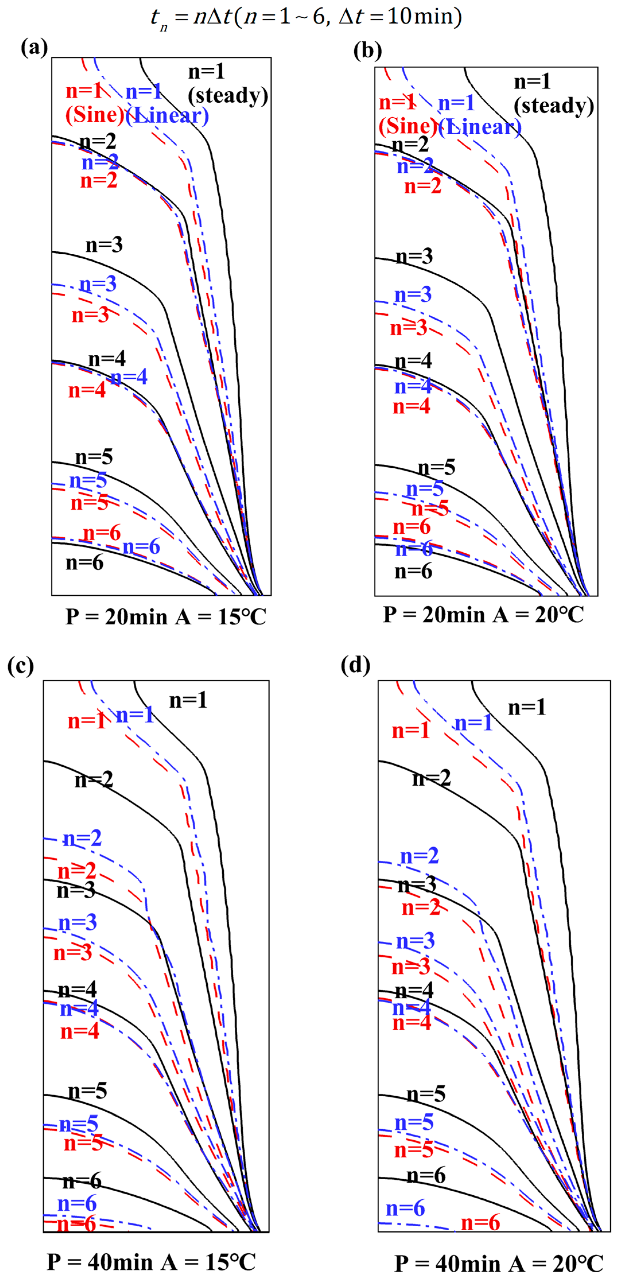
However, it can be seen from the slope of the curve that as the melting time increases, the contribution of the amplitude to the melting gradually decreases, as shown in Figure 6a; by the third cycle, the sine input and the linear input curves with the amplitudes of 15 °C and 20 °C almost coincide, and a similar phenomenon is also seen in Figure 6b.
Figure 6 displays the evolution of the melt front under different amplitudes and periods, respectively, which were recorded every ten minutes (set Δ t = 10 ) for one hour, with an initial hot wall temperature of 70 °C. The black solid contours represent the 70 °C steady input, the blue dotted contours represent the linear input, and the red dashed contours represent the sinusoidal input. The contours at different moments are denoted as t n .
t n = n Δ t   n = 1,2 , 3,4 , 5,6   Δ t = 10   m i n
Figure 6a,b illustrate the evolution of the liquid front at the amplitudes 15 °C and 20 °C over a 20 min period. Compared with the black solid contours, the distance between the red dashed contours and the blue dotted contours of the first two periods in the melt rise period increases in the same period, showing a tendency for the sinusoidal input to be greater than the linear input, and both significantly promote the PCM melt rate. As the amplitude increases, the contribution of the two inputs to the PCM melting increases, but their distance difference in the vertical direction is almost the same, which means that the increase in the amplitude has almost the same impact on the sinusoidal input and the linear input. During the melting-down period ( t 2 , t 4 ) of the first two cycles, the melting rate of PCM is the same for the three inputs, showing that the sinusoidal input and linear input significantly accelerate the melting of PCM during the melting-rise period. From the last cycle, it can be seen that even in the melting-rise phase ( t 5 ), the promotion effect caused by increasing the amplitude is not as good as that of the first two cycles. As shown, as the distance difference between the three inputs becomes smaller and smaller, in the second half of the last cycle ( t 6 ), the PCM melting rate of the constant temperature input is even slightly higher than that of the other two inputs, and the PCM melting rate of the linear input and sine input is almost the same. Sinusoidal input is a better way to accelerate PCM melting than linear input at a certain period with increasing amplitude, even though both have almost the same melting rate for PCM at the last temperature drop period. However, from the whole period, with the climb in amplitude, the melting rate in the first forty minutes is higher than the constant temperature, but it is slightly lower than the constant temperature in the last twenty minutes. This is due to a significant increase in the heat flux generated in the early stage by increasing the amplitude, while the heat flux decreases in the second half of the period as the temperature decreases.
When the period is extended to 40 min, the same phenomenon occurs in Figure 6c,d. The melting rate slows down in the second half of the melting period, and the increase in melting rate caused by the increase in amplitude is more obvious.

3.3. Effect of Sinusoidal Input Period

Once the impact of the amplitude on melting is established, the melting rate can be further optimized by adjusting the period of the input while keeping the amplitude constant. The liquid fractions simulated for different sinusoidal periods (10 min, 20 min, and 40 min) at fixed amplitudes of 10 °C and 15 °C are examined in Figure 7. In Figure 7a, compared with the constant temperature, it is evident that the input of different periods significantly increases the averaged melting rate of the PCM in the temperature-rise period. The 10 min and 20 min periods are slightly lower than the constant temperature at the end of the temperature-drop period in the last 30 min, but the relative decline is almost negligible. After several input periods of PCM melting, as the melting time increases, the influence of the period on melting becomes smaller, resulting in a gradual decrease in heat flux, causing the melting rate of the PCM to be lower than that of the constant-temperature input during the descending stage of melting and higher than that of the constant-temperature input during the ascending stage of melting. The melting rate of the 40 min period is always higher than the constant temperature, and its averaged melting rate is the highest, much higher than those of the 10 min and 20 min periods. However, for the short period, the influence of sine input on PCM melting is almost the same as that of linear input. For the period of 40 min, an obvious difference emerges, but the two curves nearly coincide as the temperature drops.
It is also noted that, compared with the 40 min period, periods of 10 min and 20 min have a more pronounced effect on PCM melting promotion during the first period of temperature rise, while it tends to stabilize later. This suggests that the lower periods have a faster temperature rise during the temperature-rise period, but the relative duration of the rise period is too short. Similar results can also be found when amplitude grows, as shown in Figure 7b.
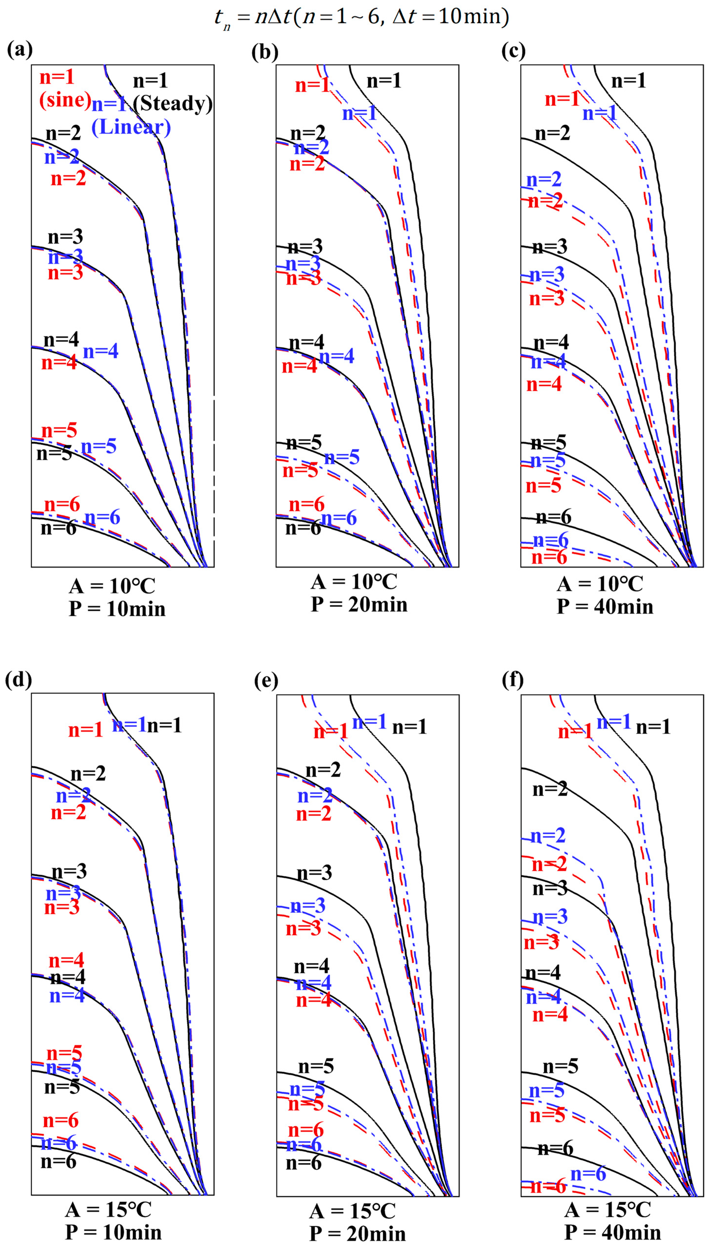
Figure 8a shows that under the ten-minute period, there is almost no difference in the degree of influence of the three inputs on the melting rate of PCM. This may be due to the relatively small impact of low periods on PCM melting. In Figure 8b,c, at a fixed amplitude of 10 °C, when the melting process reaches ten minutes ( t 1 ), both sinusoidal and linear inputs have the same promoting effect on PCM. However, at 20 min of melting ( t 2 ), the three input melting rates are the same in the 20 min period, and at the 40 min period, the red dashed contours and blue dotted contours are moving at a faster pace than the black solid contours, and the sine input melting rate is higher. With increasing melt time, the 20 min period shows that the sinusoidal and linear inputs are higher than the constant inputs during the melt-rise period, while the melting rates are the same during the melt-fall period. The melting rates of PCM for sinusoidal and linear inputs are always higher than those for constant inputs at a 40 min period, but the decrease in the distance difference between the three inputs on the vertical contours indicates that the melting rates for the sinusoidal and linear inputs are gradually decreasing but are still much higher for a limited time than for the constant inputs. This means that the large-period input method has a significant effect on increasing the heat flux during the melting-rise period. Even if the influence of the period on the melting rate gradually decreases, the melting process of PCM can be accelerated by extending the period.
Similar phenomena are also seen in different fixed amplitudes of 15 (Figure 8d–f). At higher amplitudes, the impact of the three different input periods on PCM melting will be greater, but they will not change the way the period affects PCM melting.

3.4. Comparison between Sine Input and Other Input Melting Rates

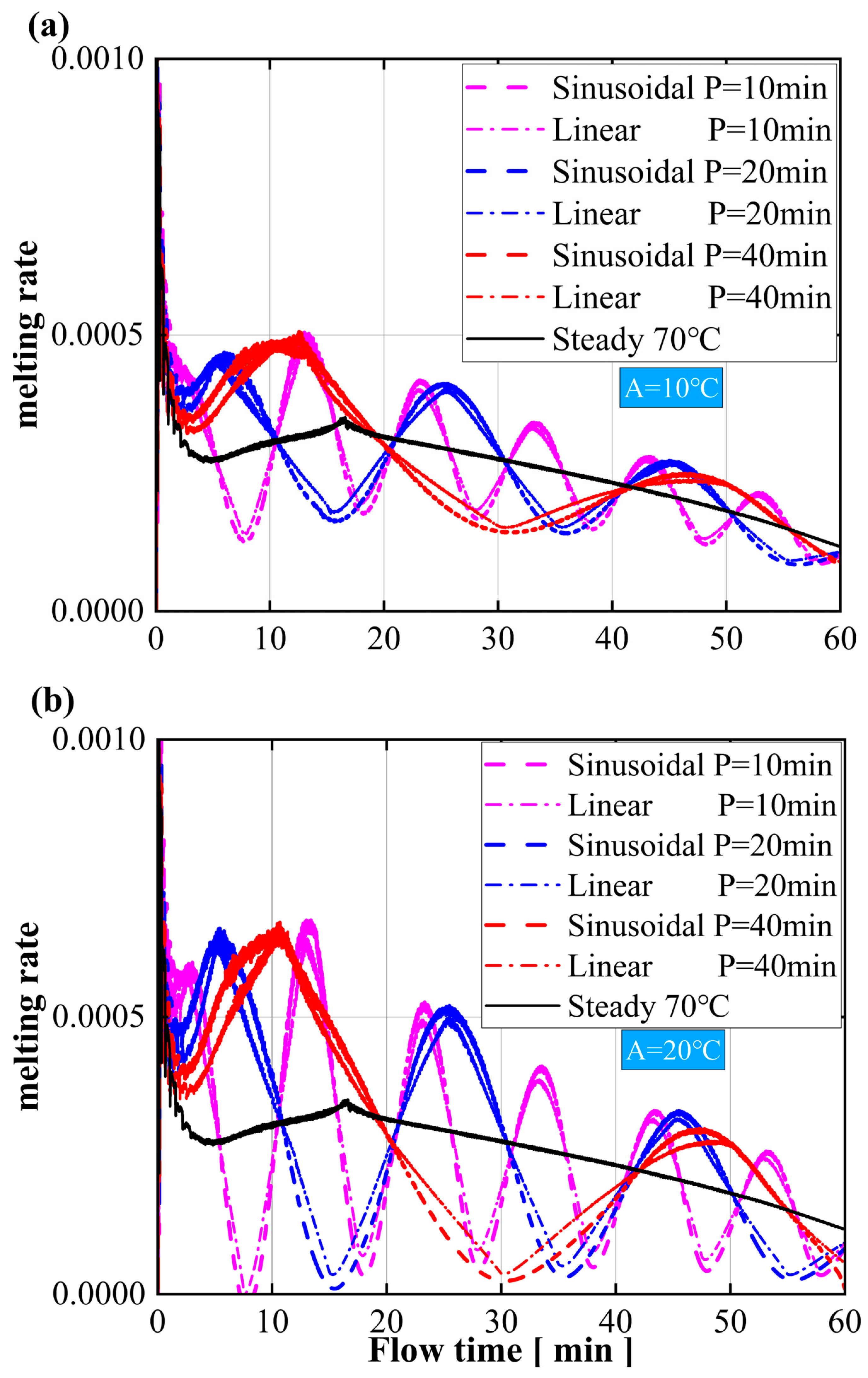
The curve shown in Figure 9 is calculated for the derivation of the melting rate under three input modes of PCM.
v = d γ d t
where v is the melting rate (s−1), t is the time variable (s), and γ is the liquid fraction.
It shows the melting rate under three input modes of different amplitudes and different periods at different times. On the one hand, it demonstrates the better input mode, and on the other hand, it determines the influence of amplitude and period parameters on sine input and linear input.
To verify the impact of the input period and amplitude on the melting rate of PCM, Figure 9 compares the melting rates between different periods within 60 min under 10 °C and 20 °C amplitudes. The results demonstrate that, as illustrated in Figure 9a, the 10 min, 20 min, and 40 min periods account for 48.8%, 49.3%, and 55.2% of the total melting time, respectively, in promoting melting. As illustrated in Figure 9b, the 10 min, 20 min, and 40 min periods account for 48.2%, 49%, and 55% of the total melting time, respectively, in promoting melting. Furthermore, the peak melting rate of the different periods is almost consistent, and as the amplitude increases, the peak melting rate also significantly increases. As the melting time increases, the melting rate gradually decreases. Since the periodic amplitudes of the linear input and the sinusoidal input are the same, it is obvious from the figure that the two inputs have the same proportion of time to promote melting, and the difference between the two inputs is locked in the melting rate during the temperature-rise period. Since the melting rate of the sinusoidal input is always higher than the linear input, the sinusoidal input should be selected as a more suitable heating mode for short-term heating.

4. Conclusions

PCM has great potential for thermal energy storage and is therefore widely used in the thermal management of electronic devices. Over the past few decades, a large number of numerical and experimental studies have been carried out by inserting various PCMs into electronic devices; however, there is a lack of guidance on the optimal heat dissipation method for PCM under cyclic thermal loads. Therefore, as an attempt, this study assessed the thermal management of electronic devices using a phase-change material (PCM) heat sink under cyclic thermal loads. Three thermal input modes—two periodic and one constant—were evaluated to determine the optimal heat storage and dissipation strategy for the PCM. The effect of the heated wall input period and amplitude on the melting rate of the PCM was investigated. Finally, an optimum heat storage combination of input period and temperature amplitude was deduced. The main conclusions are summarized as follows:
(1)
Under identical amplitude conditions, the peak melting rate remains consistent, with longer periods resulting in a longer promotion of melting. Conversely, under similar conditions, larger amplitude values result in faster melting rates. In other words, the period increases the heat flux output by extending the temperature-rise period, prolonging the promotion of the melting process. The amplitude affects the heat flux by adjusting the temperature to increase the melting rate. Although the efficiency diminishes over time, the combination of long periods and high amplitudes significantly accelerates the initial phase of PCM melting.
(2)
The sinusoidal input is superior to the linear input in improving the PCM’s heat storage and dissipation at the same amplitude during long periods. However, for short periods, both input modes yield similar results. If the holding period is constant, even under small amplitudes, sinusoidal input is better than linear input. Additionally, for rapid heat storage and dissipation, a short-period, high-amplitude sinusoidal input is ideal. For extended heat dissipation, a long-period, high-amplitude sinusoidal input is recommended.
(3)
Under long-time input, the averaged melting rate of the three input modes will be gradually close to each other. After several cycles of short-period input, the PCM’s heat storage efficiency will continue to decline, even lower than with the constant input. Therefore, for higher efficiency, the device should be shut down and allowed to rest after long-term operation so that the PCM system can regain its heat absorption and dissipation capabilities.

Author Contributions

Investigation, supervision, F.Y.; writing—original draft, data curation, Y.D.; writing—review and editing, M.O.; resources, supervision, L.Z.; writing—review and editing, C.Z. All authors have read and agreed to the published version of the manuscript.

Funding

The work was supported by the Natural Science Foundation of Hubei Province of China (Grant No. 2023AFB400), Key Laboratory of Transport Industry of Port Cargo Handling Technology (Wuhan University of Technology), Ministry of Transport, PRC (No. GKZX 2023003) and Doctoral Research Start-up Fund of Hubei University of Technology (Grant No. XJKY20240065).

Data Availability Statement

The original contributions presented in the study are included in the article; further inquiries can be directed to the corresponding author.

Conflicts of Interest

The authors declare no conflicts of interest.

Nomenclature

C mushy-zone constant, k g / m 3 s ρ density, kg/m3
c p specific heat, J / k g K σ computational constant
A amplitude of periodic inputSubscripts
P period of periodic inputlliquidus
g gravitational acceleration, m / s 2 refreference
hspecific enthalpy, J/kgssolidus
hsflatent heat of fusion, J/kgwwall
Henclosure height, mndifferent moment
kthermal conductivity, W/(m·K)0initial
Lenclosure length, mAbbreviations
ttime, sCFDcomputational fluid dynamics
Ttemperature, KEDselectronic devices
vmelting rate, s−1PCMphase-change material
t n contours at different moments, minPRESTO!pressure staggering option
nserial numberQUICKquadratic upstream interpolation for
Greek letters convective kinematics
βthermal expansion coefficient, 1/KSIMPLEsemi-implicit method for pressure-
γ liquid phase fraction linked equation
μ dynamic viscosity, Pa·sTMSthermal management system

References

  1. Liu, H.; Yu, J.; Wang, R. Model predictive control of portable electronic devices under skin temperature constraints. Energy 2022, 260, 125185. [Google Scholar] [CrossRef]
  2. Zhao, C.R.; Mazo, J.R.; Verstraete, D. Optimisation of a liquid cooling system for eVTOL aircraft: Impact of sizing mission and battery size. Appl. Therm. Eng. 2024, 246, 122988. [Google Scholar] [CrossRef]
  3. Zhao, C.R.; Clarke, M.; Kellermann, H.; Verstraete, D. Liquid cooling systems for batteries of electric vertical takeoff and landing aircraft. J. Aircraft 2024, 61, 667–683. [Google Scholar] [CrossRef]
  4. Liu, H.R.; Li, B.J.; Hua, L.J.; Wang, R.Z. Designing thermoelectric self-cooling system for electronic devices: Experimental investigation and model validation. Energy 2022, 243, 123059. [Google Scholar] [CrossRef]
  5. Su, G.; Zhang, Y.; Cai, L.; Su, S.; Chen, J. Conceptual design and simulation investigation of an electronic cooling device powered by hot electrons. Energy 2015, 90, 1842–1847. [Google Scholar] [CrossRef]
  6. He, Z.; Yan, Y.; Zhang, Z. Thermal management and temperature uniformity enhancement of electronic devices by micro heat sinks: A review. Energy 2021, 216, 119223. [Google Scholar] [CrossRef]
  7. Han, D.L.; Yang, L.Y.; Wang, S.P.; Zeng, X.Q.; Tang, L.; Liu, K.; Liang, K.; Shen-Tu, H.Q.; Guo, L.Q.; Bai, L.; et al. Thermally conductive composite phase change materials with excellent thermal management capability for electronic devices. J. Mater. Sci. Mater. Electron. 2022, 33, 1008–1020. [Google Scholar] [CrossRef]
  8. Liu, Y.; Zheng, R.; Li, J. High latent heat phase change materials (PCMs) with low melting temperature for thermal management and storage of electronic devices and power batteries: Critical review. Renew. Sustain. Energy Rev. 2022, 168, 112783. [Google Scholar] [CrossRef]
  9. Righetti, G.; Zilio, C.; Hooman, K.; Mancin, S. Market-orientated solutions to increase thermal conductivity in latent thermal energy storage systems. Appl. Therm. Eng. 2024, 243, 122583. [Google Scholar] [CrossRef]
  10. Zhu, G.; Zou, M.; Luo, W.; Huang, Y.; Chen, W.; Hu, X.; Jiang, X.; Li, Q. A polyurethane solid-solid phase change material for flexible use in thermal management. Chem. Eng. J. 2024, 488, 150930. [Google Scholar] [CrossRef]
  11. Cai, Y.; Hong, B.H.; Wu, W.-X.; Wang, W.W.; Zhao, F.Y. Active cooling performance of a PCM-based thermoelectric device: Dynamic characteristics and parametric investigations. Energy 2022, 254, 124356. [Google Scholar] [CrossRef]
  12. Wang, Y.H.; Yang, Y.T. Three-dimensional transient cooling simulations of a portable electronic device using PCM (phase change materials) in multi-fin heat sink. Energy 2011, 36, 5214–5224. [Google Scholar] [CrossRef]
  13. Boldoo, T.; Chinnasamy, V.; Cho, H. Enhancing efficiency and sustainability: Utilizing high energy density paraffin-based various PCM emulsions for low-medium temperature applications. Energy 2024, 303, 131988. [Google Scholar] [CrossRef]
  14. Zhao, C.R.; Opolot, M.; Liu, M.; Bruno, F.; Mancin, S.; Hooman, K. Phase change behaviour study of PCM tanks partially filled with graphite foam. Appl. Therm. Eng. 2021, 196, 117313. [Google Scholar] [CrossRef]
  15. Yang, Q.; Yao, H.; Yang, Y.; Azaiez, M. Effect of contact thermal resistance and skeleton thermodynamic properties on solid-liquid phase change heat transfer in porous media: A simulation study. Energy 2024, 300, 131532. [Google Scholar] [CrossRef]
  16. Fekadu, B.; Assaye, M. Enhancement of phase change materials melting performance in a rectangular enclosure under different inclination angle of fins. Case Stud. Therm. Eng. 2021, 25, 100968. [Google Scholar] [CrossRef]
  17. Yang, X.; Wang, X.; Liu, Z.; Luo, X.; Yan, J. Effect of fin number on the melting phase change in a horizontal finned shell-and-tube thermal energy storage unit. Sol. Energy Mater. Sol. Cells 2022, 236, 111527. [Google Scholar] [CrossRef]
  18. Zhao, C.R.; Wang, J.; Sun, Y.; He, S.; Hooman, K. Fin design optimization to enhance PCM melting rate inside a rectangular enclosure. Appl. Energy 2022, 321, 119368. [Google Scholar] [CrossRef]
  19. Kalbasi, R.; Afrand, M.; Alsarraf, J.; Tran, M.-D. Studies on optimum fins number in PCM-based heat sinks. Energy 2019, 171, 1088–1099. [Google Scholar] [CrossRef]
  20. Wang, C.Y.; Mobedi, M. A comprehensive pore scale and volume average study on solid/liquid phase change in a porous medium. Int. J. Heat Mass Transf. 2020, 159, 120102. [Google Scholar] [CrossRef]
  21. Zhao, C.R.; Opolot, M.; Liu, M.; Wang, J.; Bruno, F.; Mancin, S.; Hooman, K. Periodic Structures for Melting Enhancement: Observation of critical cell size and localized melting. Int. J. Heat Mass Transf. 2022, 195, 123107. [Google Scholar] [CrossRef]
  22. Zhao, C.R.; Opolot, M.; Keane, P.; Wang, J.; Liu, M.; Wang, J.; Bruno, F.; Mancin, S.; Hooman, K. Thermal Characteristics of Melting of a Phase Change Material Enhanced by a Stainless-Steel 304 Periodic Structure. Energy Storage Sav. 2023, 2, 442–448. [Google Scholar] [CrossRef]
  23. Zhao, C.R.; Sun, Y.B.; Wang, J.; Hooman, K. The applicability of volume-averaging method to simulate melting in a multi-scaled periodic structure. Energy 2022, 248, 123636. [Google Scholar] [CrossRef]
  24. Eswaramoorthy, M.; Bhagat, A.K. An experimental study on flexible phase change material for compact electronic device applications. Mater. Today Proc. 2023, 90, 76–80. [Google Scholar]
  25. Zhang, D.X.; Zhu, C.Y.; Huang, B.H.; Duan, X.Y.; Gong, L.; Xu, M.H. Thermal control performance evaluation of a phase change material-based heat sink for the electronic device suffering transient heat flux shock. Appl. Therm. Eng. 2023, 230, 120760. [Google Scholar] [CrossRef]
  26. Qu, J.G.; Liu, Y.; Zhang, J.F.; Jin, Z.G.; Chen, Y.S.; Zhao, X. Experimental study on heat transfer during melting in metal and carbon foam saturated with phase-change materials for temperature control in electronic devices. Appl. Therm. Eng. 2024, 236, 121681. [Google Scholar] [CrossRef]
  27. Turki, A.F.; Mahdy, O.S.; Abu-Hamdeh, N.H.; Jasim, D.J.; Milyani, A.H.; Kazemi-Varnamkhasti, H.; Alizadeh, A.; Nasajpour-Esfahani, N.; Toghraie, D. Investigating the thermal performance of nano-encapsulated phase change materials-water nanofluid in the presence of a heat source as applied in electronic devices. J. Taiwan Inst. Chem. Eng. 2023, 150, 105030. [Google Scholar] [CrossRef]
  28. Li, J.; Duan, W.; Chen, Y.; Chen, H.; Song, M.; Liao, S.; Shi, E.; Sun, X. Thermal performance of pin fin heat sinks with phase change material for electronic devices thermal management. Appl. Therm. Eng. 2024, 250, 123456. [Google Scholar] [CrossRef]
  29. Zahid, I.; Farhan, M.; Farooq, M.; Asim, M.; Imran, M. Experimental investigation for thermal performance enhancement of various heat sinks using Al2O3 NePCM for cooling of electronic devices. Case Stud. Therm. Eng. 2023, 41, 102553. [Google Scholar] [CrossRef]
  30. Mirza, S.; Amon, C.H.; Chandra, S. Thermal response to periodic heating of a heat sink incorporating a phase change material. Int. J. Heat Mass Transf. 2024, 229, 125761. [Google Scholar] [CrossRef]
  31. Biswas, N.; Manna, N.K.; Mahapatra, P.S. Merit of non-uniform over uniform heating in a porous cavity. Int. Commun. Heat Mass Transf. 2016, 78, 135–144. [Google Scholar] [CrossRef]
  32. Djebali, R.; Ferhi, M. Appraising heat transfer enhancement by nanofluid and entropy generation minimization in a micro tall cavity: Magnetic field and sinusoidal heating effects. In Proceedings of the 2022 13th International Renewable Energy Congress (IREC), Hammamet, Tunisia, 13–15 December 2022; Institute of Electrical and Electronics Engineers Inc.: Hammamet, Tunisia, 2022; pp. 1–4. [Google Scholar]
  33. Hayat, M.; Ali, H.; Janjua, M.; Pao, W.; Li, C.; Alizadeh, M. Phase change material/heat pipe and Copper foam-based heat sinks for thermal management of electronic systems. J. Energy Storage 2020, 32, 101971. [Google Scholar] [CrossRef]
  34. Kong, X.; Nie, R.; Yuan, J. Shape stabilized three-dimensional porous SiC-based phase change materials for thermal management of electronic components. Chem. Eng. J. 2023, 462, 142168. [Google Scholar] [CrossRef]
  35. Ma, Y.; Wang, H.; Zhang, L.; Sheng, X.; Chen, Y. Flexible phase change composite films with improved thermal conductivity and superb thermal reliability for electronic chip thermal management. Compos. Part A—Appl. Sci. Manuf. 2022, 163, 107203. [Google Scholar] [CrossRef]
  36. Nofal, M.; Al-Hallaj, S.; Pan, Y. Thermal management of lithium-ion battery cells using 3D printed phase change composites. Appl. Therm. Eng. 2020, 171, 115126. [Google Scholar] [CrossRef]
  37. Wang, B.; Li, G.; Xu, L.; Liao, J.; Zhang, X. Nanoporous Boron Nitride Aerogel Film and Its Smart Composite with Phase Change Materials. ACS Nano 2020, 14, 16590–16599. [Google Scholar] [CrossRef] [PubMed]
  38. Wang, S.; Zhang, D.; Li, C.; Wang, J.; Zhang, J.; Cheng, Y.; Mei, W.; Cheng, S.; Qin, P.; Duan, Q.; et al. Numerical optimization for a phase change material based lithium-ion battery thermal management system. Appl. Therm. Eng. 2023, 222, 119839. [Google Scholar] [CrossRef]
  39. Yang, Z.; Zhou, L.; Luo, W.; Wan, J.; Dai, J.; Han, X.; Fu, K.; Henderson, D.; Yang, B.; Hu, L. Thermally conductive, dielectric PCM-boron nitride nanosheet composites for efficient electronic system thermal management. Nanoscale 2016, 8, 19326–19333. [Google Scholar] [CrossRef] [PubMed]
  40. Zhang, Y.; Wang, K.; Sun, Y.; Xu, M.; Cheng, Z. Novel Biphasically and Reversibly Transparent Phase Change Material to Solve the Thermal Issues in Transparent Electronics. Acs Appl. Mater. Interfaces 2022, 14, 31245–31256. [Google Scholar] [CrossRef] [PubMed]
  41. Bhutto, Y.; Pandey, A.; Islam, A.; Rajamony, R.; Saidur, R. Lauric acid based form-stable phase change material for effective electronic thermal management and energy storage application. Mater. Today Sustain. 2024, 28, 100931. [Google Scholar] [CrossRef]
  42. Quoc, N.; Shabani, B. Metal hydride thermal management using phase change material in the context of a standalone solar-hydrogen system. Energy Convers. Manag. 2020, 224, 113352. [Google Scholar]
  43. Jiang, G.; Huang, J.; Fu, Y.; Cao, M.; Liu, M. Thermal optimization of composite phase change material/expanded graphite for Li-ion battery thermal management. Appl. Therm. Eng. 2016, 108, 1119–1125. [Google Scholar] [CrossRef]
  44. Li, Z.; Zhang, Y.; Cao, F.; Yang, C.; Wang, X.; Zhang, S.; Tang, B. Poly(vinyl alcohol)-Based Composite Aerogel Phase-Change Material for Thermal Management. ACS Appl. Energy Mater. 2024, 7, 3009–3017. [Google Scholar] [CrossRef]
  45. Rao, Z.; Wang, S.; Zhang, Y. Thermal Management with Phase Change Material for a Power Battery under Cold Temperatures. Energy Sources Part A—Recovery Util. Environ. Eff. 2014, 36, 2287–2295. [Google Scholar] [CrossRef]
  46. Wang, Y.; Wang, Z.; Min, H.; Li, H.; Li, Q. Performance investigation of a passive battery thermal management system applied with phase change material. J. Energy Storage 2021, 35, 102279. [Google Scholar] [CrossRef]
  47. Kamkari, B.; Shokouhmand, H.; Bruno, F. Experimental investigation of the effect of inclination angle on convection-driven melting of phase change material in a rectangular enclosure. Int. J. Heat Mass Transf. 2014, 72, 186–200. [Google Scholar] [CrossRef]
  48. Mahmoudi Larimi, Y.; Hooman, K.; Vafai, K. Convective Heat Transfer in Porous Media; CRC Press Taylor & Francis: London, UK, 2019. [Google Scholar]
  49. Shmueli, H.; Ziskind, G.; Letan, R. Melting in a vertical cylindrical tube: Numerical investigation and comparison with experiments. Int. J. Heat Mass Transf. 2010, 53, 4082–4091. [Google Scholar] [CrossRef]
  50. Yu, X.; Chang, J.; Huang, R.; Huang, Y.; Lu, Y.; Li, Z.; Wang, L. Sensitivity analysis of thermophysical properties on PCM selection under steady and fluctuating heat sources: A comparative study. Appl. Therm. Eng. 2021, 186, 116527. [Google Scholar] [CrossRef]
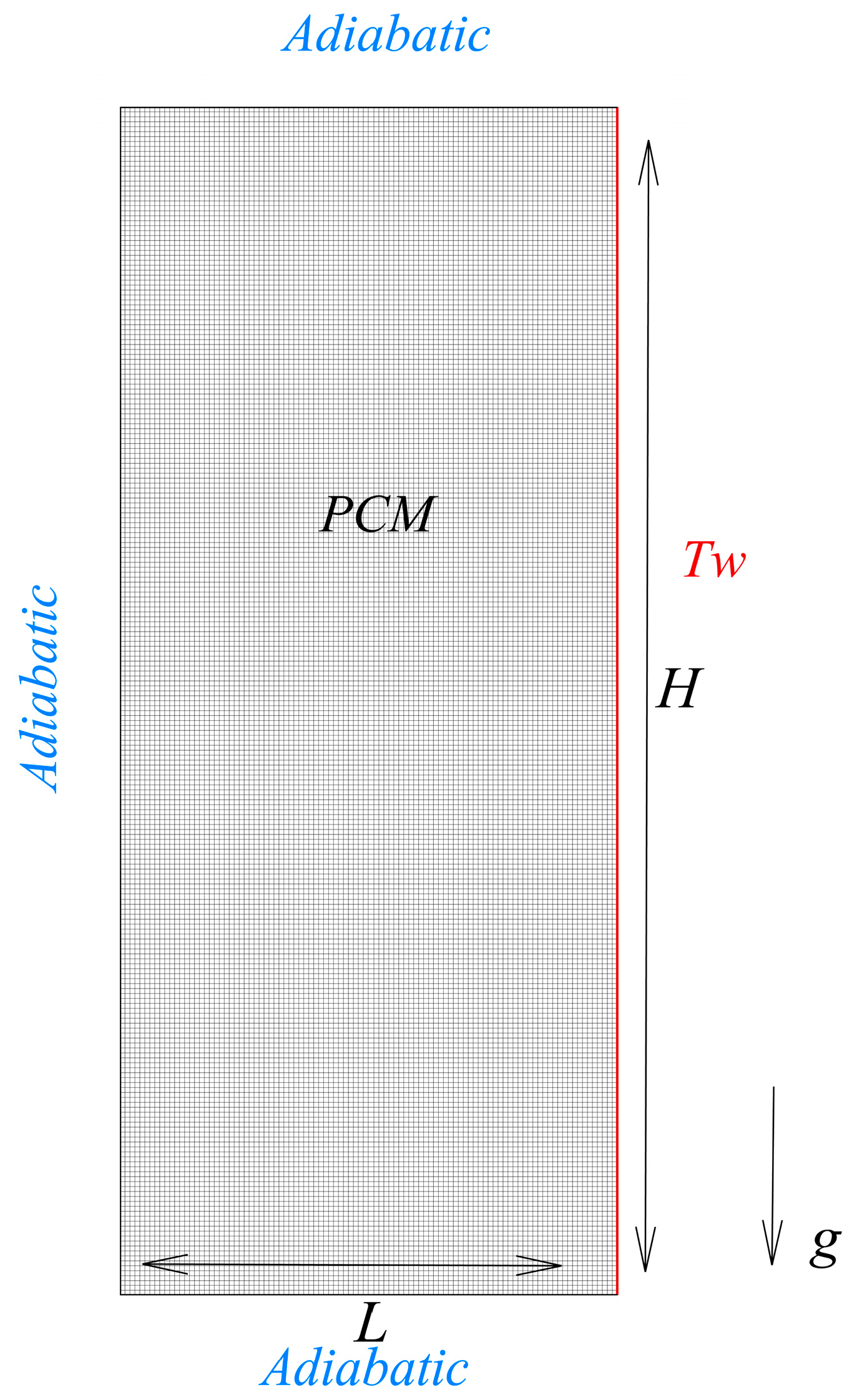
Figure 1. Schematic of PCM enclosure with the right heating and its computational mesh.
Energies 17 04888 g001
Figure 2. Temperature definition along the right heated wall, three boundary conditions can be expressed in this figure, the red dotted line represent the initial temperature with 343.15K, the red solid line represent the linear input, and the black dotted line represent the sinusoidal input. Linearly varying boundary conditions share a period and maximum/minimum values with the sine functions.
Energies 17 04888 g002
Figure 3. Independent test of grid number resolution (a) and time step size (b) and comparisons of liquid fraction evolution with experimental measurement [47] (c).
Energies 17 04888 g003aEnergies 17 04888 g003b
Figure 4. Comparison of liquid fractions of different heating strategies at fixed amplitude of 20 °C.
Energies 17 04888 g004
Figure 5. Comparison of liquid fractions of sinusoidal input, linear input, and constant temperature at fixed amplitudes with periods of 20 min (a) and 40 min (b).
Energies 17 04888 g005
Figure 6. Solid–liquid interface progress during the melting process of PCM in the rectangular enclosure with (a) P = 20 min, A = 15 °C; (b) P = 20 min, A = 20 °C; (c) P = 40 min, A = 15 °C; and (d) P = 40 min, A = 20 °C every 10 min within 60 min. The black solid contours represent the 70 °C steady input, the blue dotted contours represent the linear input, and the red dashed contours represent the sinusoidal input.
Energies 17 04888 g006
Figure 7. Comparison of liquid fractions of sinusoidal input, linear input, and constant temperature at fixed periods of amplitude of 10 °C (a) and 15 °C (b).
Energies 17 04888 g007
Figure 8. Solid–liquid interface progress during the melting process of PCM in the rectangular enclosure with (a) A = 10 °C, P = 10 min; (b) A = 10 °C, P = 20 min; (c) A = 10 °C, P = 40 min; (d) A = 15 °C, P = 10 min; (e) A = 15 °C, P = 20 min; and (f) A = 15 °C, P = 40 min every 10 min within 60 min. The black solid contours represent the 70 °C steady input, the blue dotted contours represent the linear input, and the red dashed contours represent the sinusoidal input.
Energies 17 04888 g008
Figure 9. Comparison of melting rates of sinusoidal input and constant temperature at fixed periods of amplitude of 10 °C (a) and 20 °C (b) within 60 min.
Energies 17 04888 g009
Table 1. Thermophysical properties of lauric acid [47] as the PCM.
Lauric AcidAluminum
Density solid/liquid ρ (kg/m3)940/8852700
Thermal conductivity solid/liquid k (W/m·K)0.16/0.14130
Specific heat capacity solid/liquid C P (J/kg·K)2180/2390900
Thermal expansion coefficient β (1/K)0.0008
Dynamic viscosity μ (Pa·s)0.0059
Melting point T m (K)316.65–321.35
Latent heat h s f (J/kg)187,210
Disclaimer/Publisher’s Note: The statements, opinions and data contained in all publications are solely those of the individual author(s) and contributor(s) and not of MDPI and/or the editor(s). MDPI and/or the editor(s) disclaim responsibility for any injury to people or property resulting from any ideas, methods, instructions or products referred to in the content.