Abstract
Although various hypergolic propellants like MMH/N2O4 (monomethylhydrazine/dinitrogen tetroxide) are widely used in small rocket engines, there remains a lack of in-depth study conducted on their chemical reactions and spray combustion behaviors. To fill this research gap, a simplified chemical kinetic model that is suitable for three-dimensional simulation was proposed in this paper for MMH/N2O4. Then, numerical investigation was conducted using the Volume of Fluid (VOF) model to explore the transient injection and atomization of MMH/N2O4 impinging jets in a small bipropellant thruster. Also, the instantaneous formation and evolution of the fan-shaped liquid film were analyzed. With the spray distribution determined, the proposed kinetic model and two existing mechanisms were applied to simulate spray combustion and heat transfer within the thruster, respectively, under the Euler–Lagrange framework. According to the research results, the liquid film covered nearly the entire chamber wall with a sawtooth pattern, which protected against the high temperatures of the engine wall. Notably, the two existing mechanisms showed significant errors in predicting temperature changes around the wall due to the excessively simplified reaction pathways. In contrast, the proposed model enabled the accurate prediction of the chamber pressure, wall temperature, and thrust with an error of less than 10%. Given the high accuracy achieved by the proposed numerical method, it provides a valuable reference for the development of advanced space engines.
1. Introduction
Various storable hypergolic propellants, such as monomethylhydrazine (MMH) and dinitrogen tetroxide (N2O4), have been extensively applied in space rocket engines for attitude and orbit control due to their fast ignition, variable thrust capabilities, and high specific impulse. However, little research has been conducted to explore the mechanisms of the chemical reaction and the characteristics of spray combustion in MMH/N2O4 bipropellants [1,2,3]. To a large extent, this is attributed to their extreme toxicity, corrosivity, and explosive reactivity. As space exploration advances, space propulsion systems face increasingly harsh operational environments to accomplish the missions. Therefore, it is imperative to develop high-performance space engines through a systematic investigation into the spray, combustion, and heat transfer of MMH/N2O4.
The development of accurate chemical kinetic models plays a crucial role in both experimental and computational studies of the combustion process. However, there are still few specific mechanisms proposed for MMH/N2O4. Catoire et al. [4] developed a kinetic model involving 403 elementary reactions and 82 species to describe the process of hypergolic ignition for MMH/N2O4 gas mixtures. On this basis, Anderson [5] proposed a mechanism that involves 82 species and 513 reaction steps for MMH and red fuming nitric acid. These mechanisms are considered reliable as they integrate the reaction pathways and theoretical data provided in previous studies. However, they are highly complex, which renders them unsuited to CFD applications. In order to address this issue, Hu et al. [6] developed a chemical reaction kinetic model by slightly simplifying the mechanism proposed by Anderson for MMH/N2O4, which involves 72 species and 406 elementary reactions. Additionally, Hou et al. [7] established a simplified mechanism with 23 species and 20 steps by taking into account the different reaction characteristics of the MMH/N2O4 combustion process at various stages. Although these models have been validated, the scope of their practical application is still limited due to insufficient model details. To reduce computational costs, plenty of numerical studies have been conducted on the spray combustion of MMH/N2O4, but they require the use of global reaction models that involve one or more steps [8,9]. Notably, these models often ignore the most intermediate reactions, which affects their applicability and accuracy.
In bipropellant thrusters, liquid propellants usually undergo a series of physical and chemical processes, including injection, atomization, evaporation, mixing, turbulent combustion, and conjugate heat transfer. Despite the variation in temporal and spatial scales between these processes, they are closely correlated with each other. For the accurate prediction of these multiphase combustion processes, the numerical modeling of the gas–liquid flow is indispensable [10,11]. Typically, there are two approaches adopted to serve this purpose: the Euler–Euler and Euler–Lagrange methods. Each of them has both advantages and disadvantages, depending on the specific application. Under the Euler–Lagrange framework, the liquid phase is represented by the discrete particles tracked using the Lagrangian approach, while the gas phase is solved using the Eulerian approach. However, this leads to a notable limitation that the primary atomization process cannot be resolved, which involves the formation, breakup, and atomization of the liquid sheet. To address this issue, Wei et al. [12] proposed a doublet injector model under the Euler–Lagrange framework to describe the impinging atomization of liquid propellant. This model has been applied to simulate the process of spray combustion in a 2 kN thruster for accurate prediction of propellant distributions at the impingement points. Comparatively, the Euler–Euler framework, where both the liquid and gas phases are treated as continua, is superior in predicting the atomization process by relying on its ability to capture the moving interfaces. Previous studies have demonstrated that the VOF model, a widely used subset of Eulerian models, is particularly well-suited for simulating primary breakup processes [13,14,15]. Jacobsohn et al. [16] applied the VOF model to conduct a series of simulations of impinging jet sprays given high Weber numbers, whose results are highly consistent with the experimental results. However, Eulerian models, which require the interface to be fully resolved, are heavily dependent on the grid. For the flows where the dispersed phase exhibits steep gradients and a large void, the computational cost of Eulerian models could be prohibitively high. The VOF to DPM was proposed to be addressed.
Currently, liquid film cooling is commonly practiced in small bipropellant thrusters for a compact design, with the fuel partially injected toward the combustor wall for the formation of a protective cooling film. Due to computational limits, most prior studies of rocket engine combustors focus only on the fluid domain, for which the thermal effects of the solid domain are ignored [17]. For example, Lee et al. [18] numerically investigated the effects of impingement jet cooling on combustion flow, efficiency, and wall temperature. The thermal effect in the solid region was ignored in their work. Similarly, Fu et al. [19] explored the formation and development of cooling liquid films but without considering internal heat conduction within the solid. However, the steep temperature gradients within the solid region, resulting from the presence of the liquid film, means that the accurate modeling of the heat flux and the wall temperature requires the conjugate heat transfer between the high-temperature gas and the solid region [20]. Differently, Ohminami et al. [21] considered the effects of the solid region in their study of film-cooled bipropellant thrusters based on a reduced chemical reaction mechanism. In spite of this, wall temperatures were still significantly overestimated, with an error of about 20%.
In this paper, a simplified chemical reaction mechanism suitable for MMH/N2O4 was constructed first for the purpose of three-dimensional combustion. Then, this mechanism was applied to model the jet impingement atomization, turbulent combustion, and conjugate heat transfer occurring in a small bipropellant thruster. Furthermore, the spray combustion characteristics were systematically analyzed, and the performance of different mechanisms was evaluated according to the simulation results.
2. Numerical Method
In this study, an indirect coupling methodology was adopted to accurately model the entire process of spray combustion in a small bipropellant rocket engine. The modeling process involves two primary stages. Firstly, the process of unsteady jet impingement atomization was modeled using the Volume of Fluid (VOF) method. The resulting spray characteristics at this stage were then analyzed to determine the initial droplet distributions for subsequent multi-phase combustion modeling, which was based on the Euler–Lagrange method.
2.1. VOF Model
The accurate capture of the interfaces among different phases plays a crucial role in modeling the process of complex jet impingement atomization. The configuration under consideration for the present study involves three phases: liquid MMH, liquid N2O4, and gas. The VOF model [22,23] was used to track the moving interfaces of these phases by resolving the volume fraction for each phase, which is denoted as . The volume fractions of the liquid MMH () and N2O4 () were determined by solving their respective transport equations, as expressed in Equation (1). Thus, the gas volume fraction was calculated as .
The phases share a common velocity field, resolved using a single momentum equation in conjunction with the turbulence model [24]. Through the continuum surface tension model [25], the surface tension effects at fluid interfaces were incorporated into the momentum equation. Due to the flow structures with different lengths, such as liquid sheets, large liquid lumps, and fine droplets, the computational cost incurred through comprehensive prediction can be significantly high. To prevent this, an adaptive mesh-refinement method based on octree meshes was applied [26], allowing for targeted mesh refinement in a specific region, as detailed in Section 4.
2.2. Euler–Lagrange Method
The process of spray combustion in liquid propellants was simulated using the Euler–Lagrange method. Under this framework, the liquid phase was represented by the discrete droplets tracked using the Lagrangian approach, while the gas phase was treated as a continuum and solved using the Eulerian approach. The correlation between Lagrangian droplets and Eulerian fields was incorporated through source terms in the governing equations.
2.2.1. Governing Equations of Discrete Droplets
In the Lagrangian reference frame, the trajectory of discrete droplets was predicted by integrating the motion equations, as shown in Equation (2).
where , , and represent the mass, velocity, and density of droplets, respectively; and denote the velocity and density of the gas phase, respectively; indicates the drag force coefficient, calculated using Equation (3); and refers to the additional forces, such as the virtual mass force, pressure gradient force, and thermophoretic force.
Droplets undergo intense heat exchange with the surrounding gas, which causes continuous evaporation into the gas phase. The heat transfer between droplets and the gas phase is expressed as Equation (4).
where and represent the temperatures of droplets and gas, respectively; indicates the convective heat transfer coefficient, evaluated using a modified Nusselt number; and denotes the vaporization rate of droplets, which can be calculated as follows:
where represents the droplet surface area, indicates the Spalding mass number, and denotes the mass transfer coefficient evaluated against the Sherwood number correlation.
The cooling liquid film resulting from jet-wall impingement was also represented by discrete droplets and analyzed using the Lagrangian approach. The interaction between the impinging jet and the wall was modeled using the Stanton–Rutland model [27,28], according to which the impinging droplets may stick, spread, splash, or rebound depending on their impact energy, , and the wall temperature, . The impact energy was calculated using Equation (6).
where represents the particle velocity normal to the wall, indicates the liquid density, denotes the diameter of the droplet, refers to the surface tension, means the film height, and stands for the boundary layer thickness.
2.2.2. Governing Equations of the Gas Phase
For the vaporized gas-phase reactants and combustion products, the Favre-filtered conservation equations of mass, momentum, energy, and species were solved using the Reynolds-averaged Navier–Stokes (RANS) method. They are expressed as follows:
where represents the density, indicates the velocity in i direction, p refers to the pressure, denotes the enthalpy, and stands for the mass fraction of species . Also, , , , and represent the source terms obtained from the interaction between gas and liquid phases, while and represent the source terms obtained from chemical reactions. The model [24] was used to determine the unclosed turbulent viscosity.
The conductive heat transfer within the solid region was analyzed by solving the thermal transport equation. It is presented as Equation (11) below.
where represents the thermal conductivity of the solid materials and denotes the heat source. The interface between the fluid and the solid region was modeled using a combined approach, while the outer wall surface was treated under a radiative boundary condition.
2.2.3. Turbulent Combustion Model
Due to the nonlinearity of chemical reaction source terms, it is necessary to close the RANS species transport equations through an additional turbulent combustion model. In this study, the Partially Stirred Reactor (PaSR) model, developed by Chomiak et al. [29], was adopted to deal with the interaction between turbulence and combustion. Similar to the Eddy Dissipation Concept (EDC) model [30], the PaSR model assumes that chemical reactions occur within small turbulent structures and termed fine structures, occupying a fraction of the computational cell. Thus, the chemical reaction rate depends on the reacting volume fraction, , and the residence time, , as reflected in Equation (12).
where represents the mean density, indicates the initial species mass fraction, and refers to the species mass fraction in the reactive zone.
In the standard EDC model, both and are obtained from the macroscopic flow features based on the energy cascade model, and model coefficients are constant regardless of local flow and chemical conditions. Differently, the PaSR model takes into consideration non-perfect mixing. Herein, is defined as the ratio of the chemical time scale, denoted as , to the sum of the chemical time scale and the mixing time scale, indicated by , as shown in Equation (13). The residence time within fine structures is defined as the minimum between the chemical and the mixing time scales, as shown in Equation (14).
For the PaSR model, it is essential to ensure the accurate estimation of the chemical and mixing time scales. In this paper, was determined based on the minimum chemical time scale after removal of the dormant species, as shown in Equation (15). The mixing time, denoted as , was evaluated using local flow variables, as shown in Equation (16).
where represents the constant from the turbulence model, indicates the local turbulent Reynolds number, and denotes the exponent coefficient.
At present, the PaSR model has been validated for various turbulent flames, with better performance achieved in the simulation of MILD systems and weakly turbulent reacting flows compared to the standard EDC model [31,32,33]. The PaSR model was adopted for this study given the fuel-rich and low-Reynolds number in the near-wall region of the small rocket engine with liquid film protection.
The numerical method described above is implemented using Fluent software (version 2022 R2), with the PaSR turbulent combustion model incorporated through user-defined functions and scalars. During the calculation, the Pressure Implicit with Splitting of Operators (PISO) algorithm is used to treat the pressure and flow velocity coupling. The bounded central differencing scheme is used to discretize the convection term in the momentum conservation equation and the second-order upwind scheme for the convection terms in other equations. The central differencing scheme is applied to discretize the diffusion terms.
3. Reduced Mechanisms for MMH/N2O4 Combustion
As previously discussed, a global or multi-step chemical kinetic model has been adopted in most of the existing numerical studies on the MMH/N2O4 combustion system. The combustion of MMH/N2O4 is a highly complex process involving multiple stages, such as the cold reaction, thermal decomposition, hypergolic ignition, and high-temperature combustion. This poses a challenge to accurately predicting the entire combustion process using a multi-step reaction mechanism. However, it is often costly to perform 3D combustion simulations using a detailed mechanism. To address this issue, the detailed chemical reaction mechanism for MMH/N2O4 developed by Anderson et al. [5] was simplified in this paper through the sensitivity analysis method [34]. The sensitivity coefficients of elementary reactions, denoted as , were calculated under the conditions of variable pressure (0.05–0.4 MPa), initial temperature (300–650 K), and molar ratio (0.25–4), as described in Equation (17).
where Y represents the combustion characteristic, which is defined as the ignition time herein, and indicates the model parameter of the ith reaction. By excluding the reactions with sensitivity coefficients below the established threshold, a simplified mechanism involving 31 species and 58 reactions was established.
Table 1 shows a comparison between the proposed reaction mechanism and the existing chemical kinetic models, including the detailed mechanisms proposed by Catoire et al. [4] and Anderson et al. [5], as well as the reduced mechanisms presented by Hou et al. [7] and Wei et al. [12]. To validate the reaction mechanisms, a series of MMH/N2O4 ignition simulations in a zero-dimensional closed homogeneous reactor were performed using Chemkin-Pro software (version 2022 R2). Figure 1 shows the results that demonstrate the instantaneous temperature changes under different mechanisms. Two distinct cases were analyzed, of which one involved a mixture of MMH/N2O4/NO2 at T = 298 K and P = 0.242 bar, while the other involved MMH/NO2 at T = 1000 K and P = 1 bar. The temperature changes predicted through the mechanisms proposed by Catoire et al. [4] and Anderson et al. [5] are highly consistent, indicating the reliability of these detailed mechanisms. In the absence of experimental data, the results obtained from these detailed mechanisms provide a reference for this paper. Through comparison, it is revealed that the reduced mechanism proposed by Hou et al. [7] shows a significant discrepancy, with a delayed prediction of the combustion process and an underestimation of the equilibrium temperature. The equilibrium temperatures predicted using the mechanism proposed by Wei et al. [12] are basically consistent with the reference values, despite some differences in temporal changes. Overall, the results obtained from the proposed reaction mechanism are consistent with those obtained from the detailed mechanisms, demonstrating a higher accuracy compared to the existing reduced mechanisms.

Table 1.
Comparisons of different MMH/N2O4 chemical reaction mechanisms.
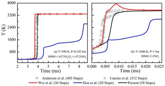
Figure 1.
Calculation results of transient ignition processes using different mechanisms [4,5,7,12].
Figure 2 illustrates the changes in equilibrium temperature and ignition delay as a function of the mixture ratio, as predicted using different mechanisms. The mixture ratio, denoted as Mr, is defined as the molar ratio of N2O4 to MMH. Four sets of cases with varying initial pressures (ranging from 1 to 30 atm) and temperatures (from 400 to 600 K) are included. Whether under low or high pressures, the prediction made using the mechanism proposed by Hou et al. [7] exhibits significant discrepancies relative to the detailed mechanisms. These discrepancies become more pronounced as the mixture ratio varies. In contrast, the mechanism proposed by Wei et al. leads to equilibrium temperature predictions highly consistent with those based on the detailed mechanisms. However, it exhibits notable discrepancies in ignition time, particularly at larger mixture ratios. Furthermore, the mechanism proposed by Wei et al. [12] shows larger errors at lower mixture ratios, as depicted in Figure 3.
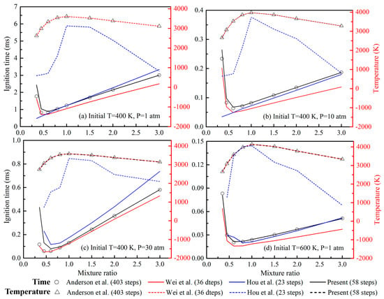
Figure 2.
Calculation results of ignition delay and equilibrium temperature using different mechanisms [5,7,12].
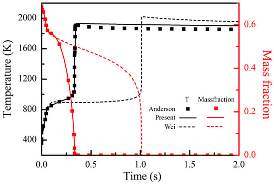
Figure 3.
Calculation results of transient ignition processes at a large mixture ratio condition [5,12].
Figure 3 presents the results of ignition obtained for an MMH/N2O4 mixture at T = 400 K, P = 30 bar, and Mr = 0.15. The combustion process predicted using the mechanism proposed by Wei et al. [12] exhibits a noticeable delay, as evidenced by the variations in temperature and MMH concentration. In such fuel-rich conditions, the reaction pathways from MMH to CO play a significant role, which results in the substantial production of CO and NH3, as illustrated in Figure 4. For the fuel-rich case depicted in Figure 3, the pathways related to HCN contribute to over 90% of CO production at the peak CO production rate. However, the mechanism proposed by Wei et al. [12] excludes these pathways, with only the conversion of MMH to HCN retained. Therefore, as shown in Figure 5, the mechanism proposed by Wei et al. [12] is used to predict a significant accumulation of HCN with minimal CO production, which results in a significant delay to the combustion process.

Figure 4.
Reactions pathways from MMH to CO.
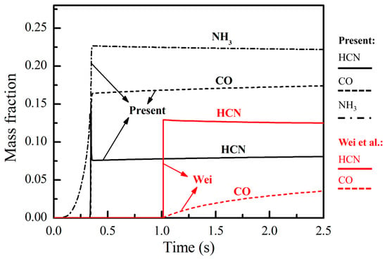
Figure 5.
Variations in intermediate species concentrations during the ignition process [12].
As revealed by the above comparisons, the results obtained using the proposed mechanism are more consistent with the reference values obtained from detailed mechanisms under various conditions. The proposed mechanism shows enhanced accuracy and stability compared to the existing models, which makes it more suitable for the modeling of three-dimensional combustion in the following sections.
4. Modeling of Atomization Dynamics of Unlike-Doublet Impinging Jets
Doublet impinging jet injectors are frequently used in small bipropellant rocket engines due to their ease of fabrication and high atomization performance. In such systems, the liquid jets of MMH and N2O4 exhibit excellent physical properties, velocities, injection angles, and nozzle sizes, which leads to an asymmetric liquid sheet upon impingement. This asymmetry adds complexity compared to symmetric configurations. In this section, the VOF model is used to explore the spray characteristics of unlike-doublet jets in practical propulsion systems through the transient simulation of the atomization process.
To simplify the computational model, only half of the combustor was included in the computational domain, with the impinging injectors positioned in the mid-plane, as depicted in Figure 6. The nozzles for MMH and N2O4, whose diameters were 0.48 mm and 0.39 mm, respectively, were used to produce jets at the injection angles of 15 and 20 degrees. The mass flux ratio of the two jets was set to 1:1.65. The computational domain was first discretized using a non-uniform grid consisting of 3.5 million hexahedral cells. Then, an automated adaptive refinement method was applied to capture the phase interfaces. Mesh refinement was controlled by the gradients in the liquid phase volume fraction, with constraints imposed on the smallest cell size (10−18 m3) and a maximum refinement level of 6. After the spray reached a steady state, the final mesh that contained over 11 million cells was obtained.
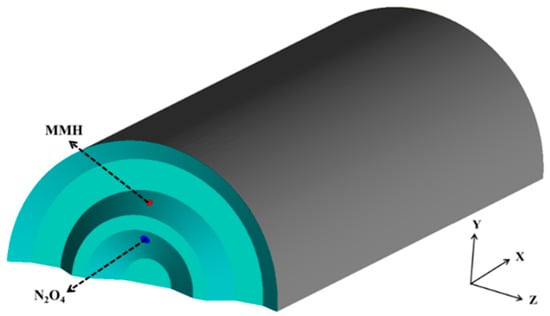
Figure 6.
Computational domain of impinging jets within a small rocket engine (green indicates the injection plane).
Figure 7 illustrates the evolution of the spray generated by the impinging jets of MMH and N2O4, as described by the iso-surface of the liquid-phase volume fraction. Initially, a fan-shaped liquid sheet develops at the point of impingement and expands downstream. With the development of unsteady waves induced by hydrodynamic instability and the interactions between the gas and liquid phases, the liquid sheet decomposes progressively into arc-shaped ligaments, large clumps, and, ultimately, finer droplets. This model is effective at capturing both the primary and secondary processes of atomization. When the spray reached a steady state by 0.5 ms, it was characterized by the periodic and consistent shedding of liquid ligaments. The steady-state spray distribution is further illustrated in Figure 8. Notably, the radial momentum is not fully neutralized due to the larger nozzle diameter and higher mass flux of the N2O4 jet compared to the MMH jet. This results in the liquid sheet moving slightly upwards, which is particularly evident in the side regions. Thus, arc-shaped distribution is exhibited in the y–z cross-section. The MMH jet remains more concentrated in the central region of the fan-shaped liquid sheet, with a smaller spray angle and larger breakup length compared to the N2O4 jet.
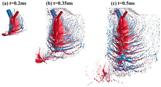
Figure 7.
Instantaneous variations of spray distribution of MMH/N2O4 (red: MMH; blue: N2O4).
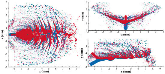
Figure 8.
MMH/N2O4 spray distribution at steady state (red: MMH; blue: N2O4).
In the subsequent simulation of spray combustion, the Euler–Lagrange method was used. Within this framework, the continuous liquid sheet was represented by discrete droplets, with their initial distributions determined using the flat-fan injection model [35]. This model requires the use of various parameters, such as the impinging point position, spray half-angle, normal vector, and orifice width. In this study, a statistical analysis of the calculated spray distributions was conducted to determine the key characteristics, such as the spatial location, spray angle, breakup length, and droplet diameter. Then, these characteristics were analyzed to improve the initial droplet settings in the flat-fan model. Figure 9 shows the discrete droplets generated by the flat-fan model in conjunction with the original liquid sheet distributions. The droplet diameters range from 15 to 125 , conforming to the Rosin–Rammler size distribution, as determined by the spray characteristics. For better visualization, the droplets in the figure are enlarged, with some droplets omitted. According to the results of the comparative analysis, the discrete droplets accurately reflect the overall distribution of the liquid sheet formed by the impinging jets, making them suitable for use as initial propellant distributions in the subsequent simulations of spray combustion.
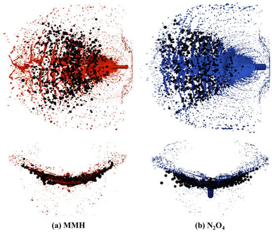
Figure 9.
MMH/N2O4 spray represented by discrete droplets(black spheres: droplets; red: MMH spray distribution; blue: N2O4 spray distribution).
5. Modeling of Spray Combustion and Heat Transfer in a Small Bipropellant Thruster
In this section, the spray combustion and heat transfer in a small bipropellant thruster are modeled through the proposed mechanism, along with two established mechanisms developed by Wei and Hou. The configuration of the thruster, as depicted in Figure 10, consists of the injection plane, a combustor, a nozzle-convergent section, and a nozzle-divergent section. The thruster carries a set of unlike impinging injectors, with MMH and N2O4 introduced via the inner and outer orifices, respectively. Additionally, an outermost orifice ring is put in place to direct some MMH fuel towards the wall for enhanced impingement cooling. Each ring is equipped with eight uniformly distributed orifices, with the injection parameters detailed in Section 4. The exhaust back pressure was set to 100 Pa, and the initial distributions of liquid propellant droplets were determined using the flat-fan injection model. Moreover, the parameters were determined according to the spray characteristics described in Section 4.
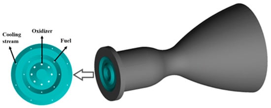
Figure 10.
Schematic of the small bipropellant thruster (green indicates the injection plane).
To reduce computational costs, only one-quarter of the symmetric cylindrical thruster was included in the computational domain. This domain was discretized using a non-uniform grid comprising 0.58 million hexahedral cells, with specific refinements in the throat and shear layer regions, as illustrated in Figure 11. The accuracy of the present model was verified by comparing numerical results with the experimental data regarding the wall temperature, chamber pressure, and thrust, as shown in Table 2. Additionally, to evaluate the grid for its sensitivity, the results obtained with the present mechanism using a refined mesh of 0.75 million cells were compared. The experimental data, including temperature, pressure, and flow sensor measurements, were collected through the hot firing tests conducted in vacuum [36]. The differences between the computational results obtained from the two mesh resolutions were found to be less than 1%, indicating the reliability of the computational mesh.
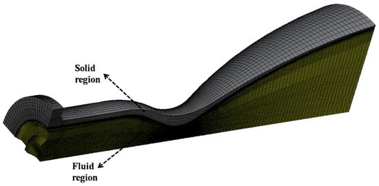
Figure 11.
Computational domain and grid.

Table 2.
Validation of critical parameter calculation results.
Compared to the experimental results, the proposed mechanism can be used to predict the chamber pressure, thrust, and wall temperature with an error of less than 5%. Although the throat wall temperature is slightly overestimated by about 70 K, these discrepancies are still acceptable given the complex interactions between high-temperature gas, liquid film, and solid regions. In contrast, the mechanism proposed by Wei et al. [12] can also be used to accurately predict the chamber pressure and thrust, but the throat temperature is significantly underestimated by 15%. The mechanism proposed by Hou et al. [7] leads to a notable underestimation of the chamber pressure, temperature, and thrust, which is consistent with the analysis of the chemical kinetic model presented in Section 2.
Figure 12 shows the comparisons of temperature distributions calculated using the three mechanisms. The presence of low-temperature regions is predominantly observed around the impingement points of the injected propellants, where intense mixing and vaporization occur. As the propellants move downstream, the temperature increases dramatically due to combustion reactions, with the chamber filled by high-temperature gas products. As shown in Figure 12, the temperature distribution predicted using the mechanism proposed by Hou et al. [7] differs significantly from those predicted by Wei et al. [12] and in the present study. The maximum flame temperature calculated by the mechanism of Hou et al. [7] is significantly underestimated, with their predicted value being approximately 2600 K. This error is primarily due to the incomplete combustion caused by oversimplified reaction routes.
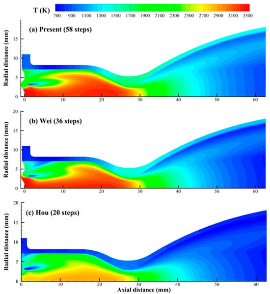
Figure 12.
Calculation results of temperature distributions using different mechanisms [7,12].
In contrast, the temperature distributions predicted by Wei et al. [12] and the present mechanism are more comparable. The main difference lies in the temperature changes at the corner of the injection plane and the side wall. As shown in Figure 12, the mechanism proposed by Wei et al. [12] is used to predict a lower temperature at this corner compared to the present mechanism. In this area, the liquid MMH partially impacts the side wall, while the remainder spreads to form a liquid film around the inner chamber wall, which gives rise to a fuel-rich region. The discrepancies in the prediction of Wei et al. [12] can be attributed to their simplified reaction pathways from MMH to CO. Because their model fails to accurately represent CO production under fuel-rich conditions, excess HCN accumulates, as depicted in Figure 13 and Figure 14. These observations are consistent with the zero-dimensional reactor calculations described in Section 2. Consequently, the wall temperature is underestimated, as detailed in Table 2, largely due to the incomplete combustion of MMH. The proposed mechanism, however, is accurate in capturing the conversion of HCN to CO in the fuel-rich region, which improves the accuracy of wall temperature prediction.
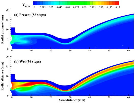
Figure 13.
Distributions of HCN concentrations calculated using different mechanisms [7].
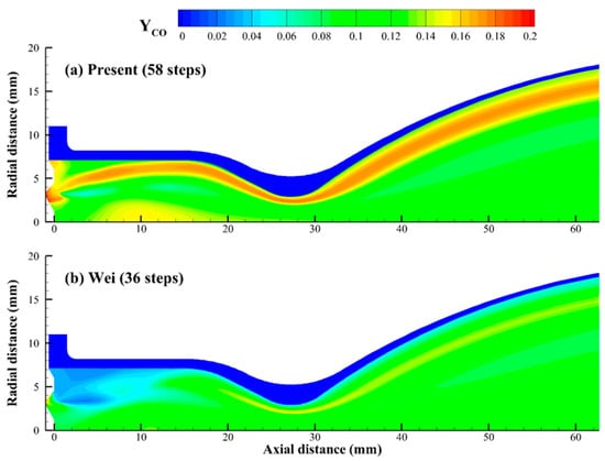
Figure 14.
Distributions of CO concentrations calculated using different mechanisms [7].
As shown in Figure 12, the liquid film forms a thin, low-temperature layer around the inner wall, resulting in a sharp radial temperature gradient. Protected by the liquid film and its vaporized gas, the chamber wall maintains a significantly lower temperature than that of the combustion gas. Figure 15 shows the distribution of temperatures on the inner and outer wall surfaces calculated using the present mechanism. Although the maximum temperature of the chamber gas exceeds 3000 K, the maximum wall temperature remains around 1700 K, highlighting the protective effect of the impinging cooling jets. Figure 16 illustrates the distribution of the height of the liquid film around the inner wall. Obviously, this height peaks below the impact point, as indicated by the black circles, before spreading both axially and radially. During this process, the film continuously absorbs heat from the gas side and ultimately evaporates near the contraction section. According to the correlation observed between Figure 15 and Figure 16, the liquid film distribution along the inner wall falls within the sawtooth-shaped low-temperature regions, which is consistent with experimental observations [36].
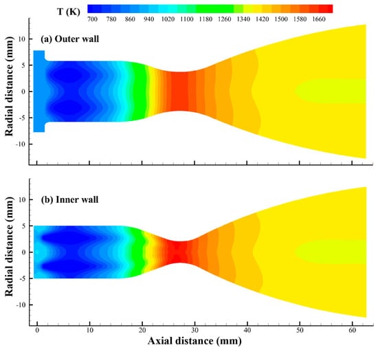
Figure 15.
Temperature distributions on the inner and outer wall surfaces predicted by the present mechanism.
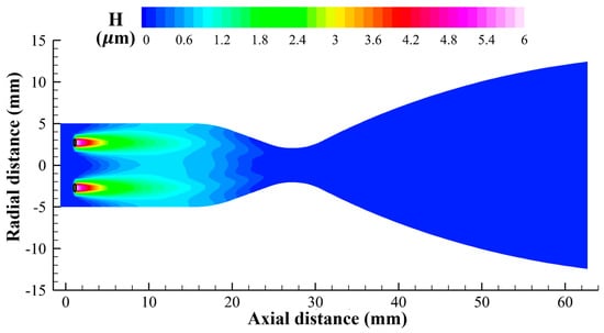
Figure 16.
Wall film height distribution on the inner wall.
Figure 17 shows the axial variations in wall temperature and heat flux. Due to the presence of liquid film, a negative heat flux develops on the front side of the chamber wall, with the initial inner wall temperature being lower than that of the outer wall. As the axial distance increases, the protective effect of the liquid film diminishes gradually, resulting in a rise in the inner wall temperature. Near the convergent section, the liquid film disappears, causing a rapid increase in the wall heat flux. Due to the significant decrease in gas temperature and pressure in the divergent region, the wall heat flux and temperature are observed to peak around the throat. It is indicated that the liquid film acting as a thermal barrier reduces the convective heat transfer from the high-temperature gas to the inner chamber wall, which indirectly mitigates the temperature rise in the throat area. Therefore, the reasonable design of the impinging cooling jets is crucial for the high performance of the engine.
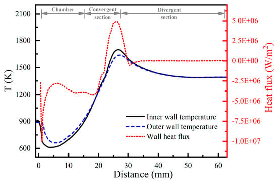
Figure 17.
Axial variations of wall temperature and heat flux.
6. Conclusions
In this paper, a simplified chemical reaction mechanism for MMH/N2O4 was developed and validated under various conditions to accurately predict the process of spray combustion in a small rocket engine. The transient simulation of injection and atomization of impinging MMH/N2O4 jets was conducted using the VOF model to examine the spray characteristics within a bipropellant thruster. Through the computed spray distributions, the proposed mechanism and two existing mechanisms, spray combustion and heat transfer, were modeled under the Euler–Lagrange framework. According to the research results, the liquid film and its vaporized gas, which form a sawtooth-patterned layer along the chamber wall, protect the engine from thermal erosion by acting as a thermal buffer between the high-temperature combustion gases and the solid wall. The non-uniform mixture distributions caused by the side-cooling jets result in complex temperature changes near the wall, where the use of existing mechanisms leads to significant predictive errors. In contrast, the proposed mechanism performs better in terms of accuracy, with the error remaining less than 10% in the chamber pressure, wall temperature, and thrust. This confirms its enhanced reliability and adaptability.
Author Contributions
Conceptualization, T.Z. and Y.W.; Methodology, T.Z. and Y.W.; Validation, J.X.; Formal analysis, Y.W.; Investigation, T.Z. and J.X.; Data curation, J.X.; Writing—original draft, T.Z.; Writing—review & editing, Y.W. All authors have read and agreed to the published version of the manuscript.
Funding
This work was financially supported by the National Natural Science Foundation of China (U21B2088).
Data Availability Statement
The original contributions presented in the study are included in the article, further inquiries can be directed to the corresponding author.
Conflicts of Interest
The authors declare no conflict of interest.
References
- Hayashi, J.; Tani, H.; Kanno, N.; Sato, D.; Daimon, Y.; Akamatsu, F.; Gabl, J.; Black, A.; Pourpoint, T. Multilayer reaction zones of a counterflow flame of gaseous Nitrogen Tetroxide and a liquid Monomethylhydrazine pool. Combust. Flame 2019, 201, 244–251. [Google Scholar] [CrossRef]
- Black, A. Liquid and Gas Phase Chemistry of Hypergolic Reactions between MMH and NTO or RFNA. Master’s Thesis, Purdue University, West Lafayette, IN, USA, 2017. [Google Scholar]
- Wu, J.; Bruce, F.N.O.; Bai, X.; Ren, X.; Li, Y. Insights into the Reaction Kinetics of Hydrazine-Based Fuels: A Comprehensive Review of Theoretical and Experimental Methods. Energies 2023, 16, 6006. [Google Scholar] [CrossRef]
- Catoire, L.; Chaumeix, N.; Paillard, C. Chemical kinetic model for monomethylhydrazine/nitrogen tetroxide gas phase combustion and hypergolic ignition. J. Propuls. Power 2004, 20, 87–92. [Google Scholar] [CrossRef]
- Anderson, W.R.; McQuaid, M.J.; Nusca, M.J.; Kotlar, A. A Detailed, Finite-Rate, Chemical Kinetics Mechanism for Monomethylhydra-zine-Red Fuming Nitric Acid Systems; Army Research Lab: Adelphi, MD, USA, 2010. [Google Scholar]
- Hu, H.; Chen, H.; Yan, Y.; Zhang, F. Investigation of Chemical Kinetic Model for Hypergolic Propellant of Monomethylhydrazine and Nitrogen Tetroxide. J. Energy Resour. Technol. 2021, 143, 062304. [Google Scholar]
- Hou, L.; Fu, P.; Ba, Y. Chemical mechanism of MMH/NTO and simulation in a small liquid rocket engine. Combust. Sci. Technol. 2018, 191, 2208–2225. [Google Scholar] [CrossRef]
- Qin, J.; Zhang, H. Numerical analysis of self-excited combustion instabilities in a small MMH/NTO liquid rocket engine. Int. J. Aerosp. Eng. 2020, 2020, 3493214. [Google Scholar] [CrossRef]
- Lee, K.H. Numerical simulation on thermal and mass diffusion of MMH–NTO bipropellant thruster plume flow using global kinetic reaction model. Aerosp. Sci. Technol. 2019, 93, 104882. [Google Scholar] [CrossRef]
- Chen, X.; Yang, V. Recent advances in physical understanding and quantitative prediction of impinging-jet dynamics and atomization. Chin. J. Aeronaut. 2019, 32, 45–57. [Google Scholar] [CrossRef]
- Gorokhovski, M.; Herrmann, M. Modeling primary atomization. Annu. Rev. Fluid Mech. 2008, 40, 343–366. [Google Scholar] [CrossRef]
- Wei, Q.; Liang, G. Numerical simulation of ignition process for the monomethyl hydrazine–nitrogen tetroxide thrusters. J. Propuls. Power 2019, 35, 704–719. [Google Scholar] [CrossRef]
- Shinjo, J. Recent advances in computational modeling of primary atomization of liquid fuel sprays. Energies 2018, 11, 2971. [Google Scholar] [CrossRef]
- Balasubramanian, A.K.; Kumar, V.; Nakod, P.; Schütze, J.; Rajan, A.; Sweeney, B.A.; Frederick, R.A.; Sim, J.; Badra, J.A.; Im, H.G.; et al. Multiscale modelling of a doublet injector using hybrid VOF-DPM method. In Proceedings of the AIAA Scitech 2020 Forum, Orlando, FL, USA, 6–10 January 2020; p. 2284. [Google Scholar]
- Kuznetsov, V.; Shebelev, A.; Sharypov, O.; Dekterev, A.; Minakov, A. Simulation of the liquid fuel spraying based on Eulerian-Lagrangian model. J. Phys. Conf. Ser. 2019, 1359, 012080. [Google Scholar] [CrossRef]
- Jacobsohn, G.L.; Baldwin, E.T.; Schmidt, D.P.; Halls, B.R.; Kastengren, A.; Meyer, T.R. Diffuse Interface Eulerian Spray Atomization Modeling of Impinging Jet Sprays. In Proceedings of the 2018 AIAA Aerospace Sciences Meeting, Kissimmee, FL, USA, 8–12 January 2018; p. 2078. [Google Scholar]
- Zhang, G.; Li, G.; Li, L.; Tang, G. Thermal performance of MMH/NTO rocket thrust chamber based on pintle injector by using liquid film cooling. Appl. Therm. Eng. 2023, 223, 120035. [Google Scholar] [CrossRef]
- Lee, Y.W.; Jiang, T.L. Effects of Fuel Impingement-Cooling on the Combustion Flow in a Small Bipropellant Liquid Rocket Thruster. J. Mech. 2015, 31, 161–170. [Google Scholar] [CrossRef]
- Fu, P.; Hou, L.; Ren, Z.; Zhang, Z.; Mao, X.; Yu, Y. A droplet/wall impact model and simulation of a bipropellant rocket engine. Aerosp. Sci. Technol. 2019, 88, 32–39. [Google Scholar] [CrossRef]
- Shine, S.; Nidhi, S. Review on film cooling of liquid rocket engines. Propuls. Power Res. 2018, 7, 1–18. [Google Scholar] [CrossRef]
- Ohminami, K.; Ogawa, H.; Uesugi, K. Numerical bipropellant thruster simulation with hydrazine and NTO reduced kinetic reaction model. In Proceedings of the 47th AIAA Aerospace Sciences Meeting Including the New Horizons Forum and Aerospace Exposition, Orlando, FL, USA, 5–8 January 2009; p. 452. [Google Scholar]
- Hirt, C.W.; Nichols, B.D. Volume of fluid (VOF) method for the dynamics of free boundaries. J. Comput. Phys. 1981, 39, 201–225. [Google Scholar] [CrossRef]
- Du, C.; Liu, J.-Z.; Huang, Z.-Y.; Zhou, J.-H.; Cen, K.-F. VOF method for impinging-jet atomizers. Energy Fuels 2010, 24, 451–455. [Google Scholar] [CrossRef]
- Menter, F.R. Two-equation eddy-viscosity turbulence models for engineering applications. AIAA J. 1994, 32, 1598–1605. [Google Scholar] [CrossRef]
- Brackbill, J.; Kothe, D.; Zemach, C. A continuum method for modeling surface tension. J. Comput. Phys. 1992, 100, 335–354. [Google Scholar] [CrossRef]
- Popinet, S. Gerris: A tree-based adaptive solver for the incompressible Euler equations in complex geometries. J. Comput. Phys. 2003, 190, 572–600. [Google Scholar] [CrossRef]
- Stanton, D.W.; Rutland, C.J. Modeling fuel film formation and wall interaction in diesel engines. SAE Trans. 1996, 105, 808–824. [Google Scholar]
- O’Rourke, P.J.; Amsden, A.A. A Spray/wall interaction submodel for the KIVA-3 wall film model. SAE Trans. 2000, 109, 281–298. [Google Scholar]
- Chomiak, J. Combustion: A Study in Theory, Fact and Application; Abacus Press/Gorden and Breach Science Publishers: New York, NY, USA, 1990. [Google Scholar]
- Ertesvåg, I.S.; Magnussen, B.F. The eddy dissipation turbulence energy cascade model. Combust. Sci. Technol. 2000, 159, 213–235. [Google Scholar] [CrossRef]
- Iavarone, S.; Péquin, A.; Chen, Z.X.; Doan, N.A.K.; Swaminathan, N.; Parente, A. An a priori assessment of the Partially Stirred Reactor (PaSR) model for MILD combustion. Proc. Combust. Inst. 2021, 38, 5403–5414. [Google Scholar] [CrossRef]
- Ferrarotti, M.; Li, Z.; Parente, A. On the role of mixing models in the simulation of MILD combustion using finite-rate chemistry combustion models. Proc. Combust. Inst. 2018, 37, 4531–4538. [Google Scholar] [CrossRef]
- Giuntini, L.; Frascino, L.; Ariemma, G.B.; Galletti, C.; Sorrentino, G.; Ragucci, R. Performance assessment of modeling approaches for moderate or intense low-oxygen dilution combustion in a scale-bridging burner. Energy Fuels 2023, 37, 9500–9513. [Google Scholar] [CrossRef]
- Turányi, T. Sensitivity analysis of complex kinetic systems. Tools and applications. J. Math. Chem. 1990, 5, 203–248. [Google Scholar] [CrossRef]
- Ansys Fluent. Ansys Fluent Theory Guide; Ansys Inc.: Canonsburg, PA, USA, 2013. [Google Scholar]
- Lin, Q. Simulation and Experiment Research on the Highly Efficient Combustion Chamber for Space Orbit Maneuvering Rocket Engine. Ph.D. Thesis, National University of Defense Technology, Changsha, China, 2015. [Google Scholar]
Disclaimer/Publisher’s Note: The statements, opinions and data contained in all publications are solely those of the individual author(s) and contributor(s) and not of MDPI and/or the editor(s). MDPI and/or the editor(s) disclaim responsibility for any injury to people or property resulting from any ideas, methods, instructions or products referred to in the content. |
© 2024 by the authors. Licensee MDPI, Basel, Switzerland. This article is an open access article distributed under the terms and conditions of the Creative Commons Attribution (CC BY) license (https://creativecommons.org/licenses/by/4.0/).