Abstract
The study describes experimental data on thermal tests during the condensation of HFE7100 refrigerant in a compact heat exchanger. The heat exchanger was manufactured using the additive 3D printing in metal. The material is AISI 316L steel. MPCM slurry was used as the heat exchanger coolant, and water was used as the reference medium. The refrigerant was condensed on a bundle of circular tubes made of steel with an internal/external diameter of di/de = 2/3 mm, while a mixture of water and phase change materials as the coolant flowed through the channels. Few studies consider the heat exchange in condensation using phase change materials; furthermore, there is also a lack of description of heat exchange in small-sized exchangers printed from metal. Most papers deal with computer research, including flow simulations of heat exchange. The study describes the process of heat exchange enhancement using the phase transition of coolant. Experimental data for the mPCM slurry coolant flow was compared to the data of pure water flow as a reference liquid. The tests were carried out under the following thermal and flow conditions: G = 10–450 [kg m−² s−1], q = 2000–25,000 [W m−²], and ts = 30–40 [°C]. The conducted research provided many quantities describing the heat exchange in compact heat exchangers, including heat exchanger heat power, heat exchange coefficient, and heat exchange coefficients for working media. Based on these factors, the thermal performance of the heat exchanger was described. External characteristics include the value of the thermal power and the heat exchange coefficient as a function of the mass flow density of the working medium and the average logarithmic temperature difference. The performance of the heat exchanger was presented as the dependencies of the heat exchange coefficients on the mass flux density and the heat flux density on the heat exchange surface. The thickness of the refrigerant’s condensate film was also determined. Furthermore, a model was proposed to determine the heat exchange coefficient value for the condensing HFE7100 refrigerant on the outer surface of a bundle of smooth tubes inside a compact heat exchanger. According to experimental data, the calculation results were in good agreement with each other, with a range of 25%. These data can be used to design mini condensers that are widely used in practice.
1. Introduction
At the end of the 20th century, there was a rapid development in technological progress, observed by a qualitative and quantitative increase in the production of devices, especially in two areas, i.e., space technology and electronics. These fields are inextricably linked, and so set the course for the miniaturization of these devices. The energy crisis of the 1970s led to the development of compact heat exchangers. The sharp increase in oil prices has moved science towards miniaturizing energy systems while increasing their efficiency. Compact heat exchangers are widely used in many branches, i.e., aviation, space, medicine, automotive industry, etc. They are particularly valued for their high thermal efficiency, small volume, and low weight. Another argument favoring compact devices is the ecological aspect; the smaller the device, the less material that is used, and the less refrigerant there is in the system. This is crucial, given the great ecological importance in protecting humanity’s natural environment. Making heat exchangers in a conventional way (which includes welding, brazing, or casting) works well in mass-producing devices with medium and large dimensions. This applies primarily to typical structures. When there is a need for precise construction of small dimensions and complex geometry, additive methods work best.
1.1. Additive Manufacturing
Currently, the development of additive manufacturing technology (3D printers) allows for a reduction of the production costs of heat exchangers with these methods, making them more and more competitive with standard manufacturing methods (welding, brazing). Modern constructions of high-efficiency heat exchangers are designed based on computer programs that enable the lossless application of technical drawings to 3D printers. It is worth remembering that, for example, the absolute thermal power value for computer systems is not very high, while the heat flux density, i.e., the amount of heat transmitted by a unit of heat exchange area, approaches significant values. Thus, searching for highly efficient cooling systems with small dimensions has become common. This applies to both heat exchangers in the form of compact evaporators and condensers, which are an integral part of small refrigeration installations. The intensity of heat exchange can be increased by using new design solutions (complex geometries) or materials with better thermal parameters. A great solution to this is the use of 3D printing for the production of high-efficiency heat exchangers made of metal.
1.2. Heat Exchange in Complex Structures
The thermo-hydraulic performance of the heat exchanger is extremely important for the heat exchanger design process. In this study, we primarily looked at heat exchange and intensification methods. One of the research studies [1] described a novel convective heat exchange enhancement method based on a precise Gyroid-type TPMS lattice structure control. The paper draws attention to the significant relationship between increasing the thermal parameters of heat exchangers and flow resistance, which generates the costs of pumping working fluids. Reynolds et al. [2] described heat exchange within 3D-printed TPMS heat exchangers. Then, a correlation was developed for the Nusselt number in the 100 < Re < 2500 range. The heat exchange performance of three types of microchannel heat exchangers was presented by Wu et al. [3]. Haertel and Nellis [4] studied topology optimization of 3D-printed air-cooled heat exchangers. A fully developed flow model was presented. A lung-inspired high-temperature ceramic 3D-printed heat exchanger was investigated by Ahmadi et al. [5]. Furthermore, a 3D-printed ceramic heat exchanger has been studied for use in air dehumidification systems [6]. Kus et al. [] presented a numerical and experimental investigation of the gyroid heat exchanger. An experimental and numerical investigation of a 3D-printed aluminum cryogenic heat exchanger for compact Brayton refrigerators was conducted by Pracht et al. [7]. Dixit et al. [8] presented a microarchitected compact heat exchanger enabled by 3D printing. Authors of the experimental study [9] developed a thermal performance model using temperature gradient analysis for the optimized design of a steam surface condenser. Li et al. [10] reviewed multiscale structural characteristics and heat–moisture properties of 3D-printed building walls. Ahmadi and Bigham [11] researched hi-k lung-inspired 3D-printed polymer heat exchangers. A U-shaped heat exchanger with 3D-printed detached curved ribs was investigated by Wang et al. [12]. The authors used PIV and IRT methods to measure the heat exchanger’s hydrothermal performance. It was found that the proposed detached curved ribs induce flow impingement on the top and bottom walls, and accelerate near-wall and core flows. Heat and flow characteristics of 3D straight and wavy channel-based printed circuit heat exchangers were presented by Khan et al. [13,14]. Lowrey et al. [15] studied the heat and flow performance of an aluminum plate heat exchanger and a 3D-printed polymer plate heat exchanger. The authors compared the dehumidification capacity of polymer and metal heat exchangers. It was found that both the aluminum control and polymer heat exchangers had very similar thermal capacities when operating in dry conditions. Still, the polymer PHE showed a greater tendency to increase the pressure drop, according to the aluminum device. Leakage characterization of ceramic 3D-printed heat exchangers was analyzed by Bayaniahangar et al. [16]. Much attention is paid to issues related to the architecture and properties of the surfaces that fill the heat exchangers. A numerical modeling of a heat exchanger filled with octahedral lattice frame porous material was presented by Zhao et al. [17]. The results showed that the proposed method can accurately predict the heat exchange process and pressure drop in the heat exchanger. Low heat capacity 3D hollow microarchitected reactors were studied for thermal and fluid applications by Kim et al. [18]. Dutkowski et al. [19] conducted a literature study on the state-of-the-art uses of minimal surfaces in heat exchange. Zhu et al. [20] proposed the application of nature-inspired structures in heat exchange enhancement and drag reduction. Pelanconi et al. [21] studied the use of ceramic lattice structures in the design of small heat exchangers. The authors drew attention to the material and architecture selection. Kelava et al. [22] investigated the stereolithography 3D printing of a heat exchanger for advanced temperature control in wire myography. Furthermore, in multiphase flow systems, the flow parameters also influence the heat transfer intensity. Wu et al. [23] studied the multiphase shear-thickening polishing process in the presence of bubbles. The currently available papers on 3D-printed heat exchangers are mainly based on simulation data. In addition, during the literature review, it was noticed that physical experiments conducted on heat exchangers refer to ceramic or polymer structures. Such materials are known for low values of thermal conductivity. That makes them not entirely suitable for heat exchange. Following the above, the authors of this paper propose a new design of a compact heat exchanger made of stainless steel using the 3D printing method. Three-dimensional printing makes it possible to increase the precision of individual elements of the exchanger, minimize geometric dimensions, maintain constant dimensions of individual elements, and increase the tightness of the exchanger. It is practically impossible to make an exchanger with such small diameters of channels using common manufacturing methods. Three-dimensional printing makes it possible to increase the compatibility of the heat exchanger and the density of the heat flux exchanged per unit of exchanger volume. This approach ensures the highest accuracy of workmanship, which is a milestone in producing small devices. Currently, 3D printing provides the possibility of serial production. An additional advantage of the proposed solution is using microencapsulated phase change material’s slurry as the heat exchange fluid receiving the heat of condensing HFE7100 refrigerant. The boiling point of HFE 7100 fluid, and its excellent environmental and health safety profile, make it a valuable product in applications such as producing heat transfer fluids. It is intended to replace products that deplete the ozone layer and contribute to global warming (GWP) in various applications. The fluid does not deplete the ozone layer, and it is environmentally friendly. It has one of the best toxicological properties among CFC substitutes, an average exposure period of 750 ppm (average 8 h), a high boiling point, and low surface tension. This makes the product ideal for applications serving as an azeotropic component, and a component in complex solvent mixtures. Additionally, its chemical and thermal stability, non-flammability, and low toxicity make this fluid suitable for other industries.
To summarize, heat exchange intensification in compact devices can be achieved by increasing the heat exchange surface with unchanged dimensions, using phase changes of working media and better cooling, including functional fluids in the form of mPCM slurries. This study attempts to use the above-mentioned methods to improve the thermal performance of a compact shell-and-tube heat exchanger.
2. The Experimental Facility
The 3D-printed heat exchanger in the measuring section is a compact shell-and-tube condenser (Figure 1). It is made of a low-carbon nickel-chromium-molybdenum-based steel alloy (SS316L), which combines excellent strength, high ductility, and good thermal properties. With its high resistance to corrosion and pitting, including chemical corrosion, this material is suitable for high-temperature applications and machine components, amongst others.
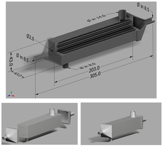
Figure 1.
Heat exchanger design with dimensions.
Furthermore, it is resistant to surface aggressive media, and heat exchangers made of this material have a high tearing strength. The heat exchanger was made according to an original design, and it is the first reference copy for a series of complex devices designed by the study’s authors (Figure 2).
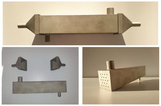
Figure 2.
Overall view of the 3D-printed heat exchanger.
The shell-and-tube mini condenser has a length of L = 203 mm. It comprises 18 channels with an internal diameter of dw = 2 mm, arranged in a checkerboard pattern. The channel wall thickness is 0.5 mm. The channels’ horizontal and vertical layouts (pitch) were Ph = 0.008 m and Pv = 0.0065 m, respectively. The channels were arranged in parallel, as shown in Figure 1. The roughness of the heat exchanger surface is in the form of an arithmetic mean deviation from the mean line; the roughness height is presented in Table 1.

Table 1.
3D heat exchanger parameters.
There are many approaches to the classification of heat exchangers. One is to base the device’s compactness on flow channel classification, a critical construction element. There are many classifications, according to Mehendale [24]. According to this classification, channels with diameters up to 6 mm are compact passages, and diameters above 6 mm are stock passages. Another classification, according to Kandlikar and Grande [25], is a bit more restrictive, and assumes that compact passages start below 3 mm. In the case of the presented device, all of the above criteria indicate that the HX fulfils the characteristics of a compact device. The heat exchanger should be considered a compact device, according to Kandlikar and Grande’s [25] classification of the passages’ compactness. The low-pressure refrigerant HFE7100 was condensed on the outer surface of the minichannels. Then, the cooling medium flowed through the minichannels driven by a pump (7). After passing the HX, the HTF was cooled in an external plate heat exchanger that was connected to the cooling unit (4). Coriolis-type mass flow meters were used to measure both the mass flow of the slurry and the refrigerant. K-type thermocouples measured both fluids’ temperatures. The data were acquired using an Endress Hauser RSG 45 data recorder. Additionally, the HFE7100 loop comprised a heated refrigerant tank (10) and pressure sensors. The diagram of the test stand is shown in Figure 3.
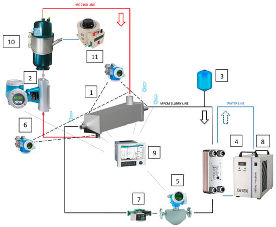
Figure 3.
Pictorial scheme of the test stand: 1, 3D heat exchanger; 2, heating fluid mass flow meter; 3, mPCM fluid storage vessel; 4, plate heat exchanger; 5, cooling fluid mass flow meter; 6, differential pressure sensor; 7, pump; 8, cooling unit; 9, data recorder; 10, heated refrigerant storage vessel; 11, autotransformer.
The thermal and flow parameters of both working fluids involved in heat exchange were measured at the test stand. The refrigerant flow rate and the mPCM slurry were measured. Pressure and temperature measurements were made for both working fluids on both sides of the exchanger (inlet and outlet), and heat exchanger tests were carried out in a steady state. The obtained measurement results allowed us to determine the remaining quantities by calculation, characterizing the heat exchange in the HX, including the heat exchanger power , the overall heat exchange coefficient k, and the heat exchange coefficients from the side of both fluids (Formulas (1)–(3)). The refrigerant saturation temperature was determined by measuring its pressure. The refrigerant mass flow rate and the geometric dimensions of the heat exchanger allowed us to determine the average thickness of the condensate film on the condensation surface (Formula (4)). However, the design of the heat exchanger did not allow for the direct measurement of this thickness. The counter-current flow was applied during the heat transfer.
Water and an aqueous solution comprising microencapsulated phase change materials in two concentrations were used as the cooling mediums. The constant flow rate of the refrigerant was obtained by regulating the thermal flow parameters of the coolant. The authors’ previous studies presented all refrigerant HFE7100 and mPCM slurry properties, i.e., specific enthalpy (Figure 4) [26,27,28,29,30,31]. Furthermore, the figure shows the beginning (25 °C) of the melting transformation process of the microcapsule content (paraffin). The moment when the paraffin completely takes on the liquid phase is also clear for t = 28 °C. It can also be seen that the process becomes more intensive with the increase in the concentration of mPCM in the slurry.
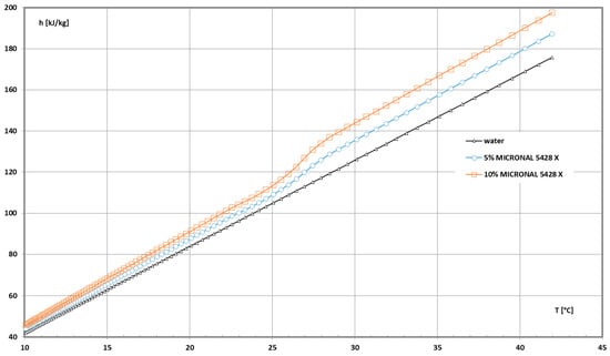
Figure 4.
The influence of coolant temperature on the specific enthalpy of the base liquid (pure water) and the slurry containing 5% and 10% mPCM.
Example values of selected parameters of mPCM slurries are presented in Table 2.

Table 2.
Properties of the mPCM slurry coolant.
3. Experimental Data
Thermal tests of the 3D-printed metal exchanger included measurements of the following parameters: saturation temperature and pressure of the HFE7100 refrigerant, the temperature of the refrigerant, and the coolant temperature during flow through the HX, as well as the mass flow rate of both media. Knowing these parameters, the heat flux received from the mPCM slurry, the value of the heat exchange coefficient from the refrigerant side, and the overall heat exchange coefficient were determined. Then, the values of the condensing refrigerant HTC were obtained based on the knowledge of the HTC on the side of the coolant.
In the tested heat exchanger, heat exchange took place on the principle of heat exchange through a cylindrical partition. Inside of the tubes, the refrigerant receiving the heat of condensation flowed, and the refrigerant condensed outside of the tubes. The heat exchanger’s heat flux was obtained with Formula (1), which is as follows:
where n is the number of minichannels, L is the heat exchanger length, λs the heat conduction coefficient for stainless steel, di is the minichannels internal diameter, de is the minichannels external diameter, αs is the coolant’s heat exchange coefficient, Δt is the refrigerant saturation temperature ts, and the average coolant temperature ts difference k value was calculated according to Formula (2), which is as follows:
The HTC of the condensing refrigerant was specified following Formula (2), which was obtained after following Formula (1)
The αs describes the heat exchange inside a tube where a single-phase liquid absorbs the condensation heat during flow. The coefficient αs was calculated following the calculation rules for forced convection in the channel. After determining the Reynolds number, Re, an appropriate computational correlation was selected for the Nusselt number, e.g., the Dittus–Boelter Formula for turbulent motion. Table 3 presents the measurement equipment uncertainty level.

Table 3.
The uncertainty of the measuring equipment.
The maximum measurement errors of the basic thermal and flow parameters are as follows: mass flux density, G = ±0.2% (max 0.7 [kg m−²s−1]); pressure, p = ±0.05% (max 100 kPa); heat flux, Q = ±2% (max 5 [W]); temperature, T = ±0.2 K; overall heat exchange coefficient, k = ±3% (max 5.4 [W m−² K]); and local heat exchange, α = ±5% (max 50 [W m−² K]).
The mean absolute square error for the heat exchange coefficient was calculated according to [9], using Formula (4), as follows:
Based on the obtained measurement data, the basic quantities describing the heat exchange in the HX were determined. Thus, it is possible to develop the external performance of the heat exchanger in the form of the dependence of the exchanger’s thermal power, Q, and the overall heat exchange coefficient, k, on the temperature of the cooling medium at the outflow from the exchanger. Figure 5 presents such a characteristic in the following, showing the relation of = f(tout), while Figure 6 shows the relation of k = f(tout).
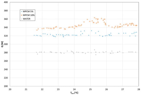
Figure 5.
The heat exchanger thermal power (heat flux) dependency on the coolant temperature at the heat exchanger outlet.
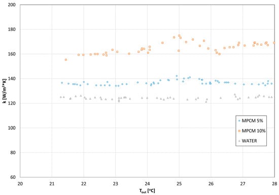
Figure 6.
The dependency of the OHTC on the coolant temperature at the exit of the HX.
It is shown that the values of the heat exchanger’s thermal power (heat flux) depend on the type of coolant. The highest values were observed during cooling with 10% mPCM slurry. Furthermore, the lowest heat flux values were noted for water cooling. It was also found that the heat flux increases during the PCM phase transition (in the temperature range of 24–26 °C); the influence of mass share on the value of heat flux was also observed. The higher the mass fraction of mPCM in the mixture, the greater the heat flux. The refrigerant saturation temperature was 30–40 °C. In the case of water cooling, the thermal power of the exchanger oscillated around 280 W; with five percent MPCM, it was around 320 W, and with ten percent MPCM, it was 340 W. During the PCM phase transition, the thermal power of the exchanger increased to 360 W.
As shown in Figure 6, the OHTC depends on the type of cooling medium. The lowest values were observed during water cooling (k ≅ 120 W/(m2·K)). The highest overall heat exchange coefficient values were noted for cooling with 10% mPCM slurry (k ≅ 160 W/(m2·K)). It was also found that the overall heat exchange coefficient increased during the PCM phase transition. For 10% mPCM, there was an increase of over 11% in the overall heat exchange coefficient (k ≅ 175 W/(m2·K). The influence of mass share on the value of heat flux was also observed. The higher the mass fraction of mPCM in the mixture, the greater the heat flux. It follows from the above that the addition of the phase change material mixture to the cooling medium intensifies the heat exchange in the heat exchanger. Thus, it can be assumed that there is an additional turbulence effect due to the presence of microcapsules in the flowing mixture.
Using Formulas (1) and (2), the quantities characterizing the condensation of the refrigerant on the tubes’ external surface inside of the heat exchanger were determined. This allowed us to develop the internal characteristics of the condensation process. Figure 7 shows the dependence of the HTC for refrigerant condensation on the tube bundle surface, depending on the q heat flux density and the difference in the saturation and channel wall temperatures (ts − tw). The increase in the heat flux density slightly affects the value of the heat transfer coefficient during the condensation of the refrigerant (from the value of αexp ≅ 800 W/(m2·K) for q = 4000 W/m2, up to αexp ≅ 900 W/(m2·K) for q = 12,000 W/m2). This is consistent with the literature data for the condensation process, where some researchers assume that, during the condensation process, the HTC coefficient does not depend on the heat flux density. Furthermore, the increase in the difference in the saturation and channel wall temperatures (ts − tw) causes a slight decrease in the value of the heat transfer coefficient within the limits given above.
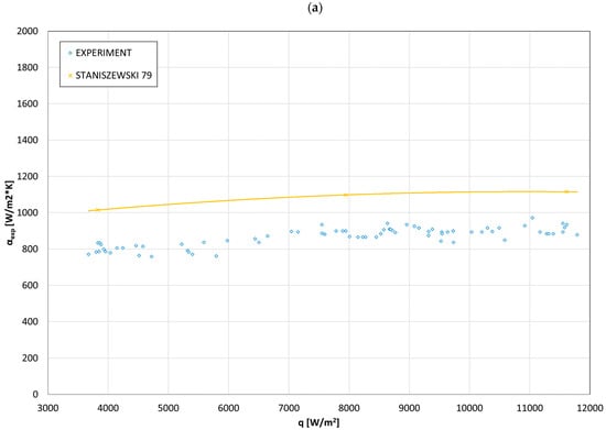
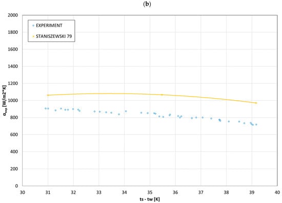
Figure 7.
Comparison of experimental and theoretical [32] data on the dependence of (a) the HTC of the refrigerant on the heat flux density; (b) the HTC of the refrigerant on the ts − tw temperature difference.
While carrying out the research, an attempt was made to replace distilled water as a factor receiving the heat of condensation in the exchanger with an aqueous solution, made of a phase change material, in order to check to what extent it would increase the thermal power of the exchanger, and the total heat transfer coefficient. This increase occurred by up to 10–11%. This was due to a decrease in thermal resistance on the coolant side. As can be seen, a similar characteristic occurs when using a computational model [32,33] describing the heat exchange during film condensation of refrigerant vapors on the outer surface of a horizontal channel.
where ts and tw are saturation and wall temperature, respectively.
The obtained measurement data allowed us to determine the detailed values describing the condensation process, including the thickness, δ, and the velocity in the refrigerant condensate film. For this purpose, dependencies (4) were used, as follows:
where δ is the thickness of the refrigerant condensate film. The recognition of the condensate thickness enables the determination of the mass flux density of the refrigerant G and the condensate velocity.
Figure 8 shows the dependence of HTC on the refrigerant’s condensate thickness. It was noted that the HTC values decrease significantly, ranging from 0.00003–0.001 m of the condensate film thickness in the range of 1100–200 W/(m2·K). This is obvious, because, during heat conduction through condensate, the thermal resistance of this condensate depends primarily on its thickness. The thicker the condensate film, the greater the resistance and the smaller the heat flow.
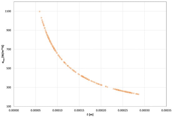
Figure 8.
The dependence of the HTC on the refrigerant condensate thickness.
Figure 9 shows the dependency of the HTC on the condensate velocity. It is noted that the value of the HTC is proportional to the increase in the condensate velocity, which results from the laminar nature of the condensate flow. An increase in the condensate velocity reduces the thickness of the condensate layer, which reduces the value of thermal resistance and increases the value of the HTC.
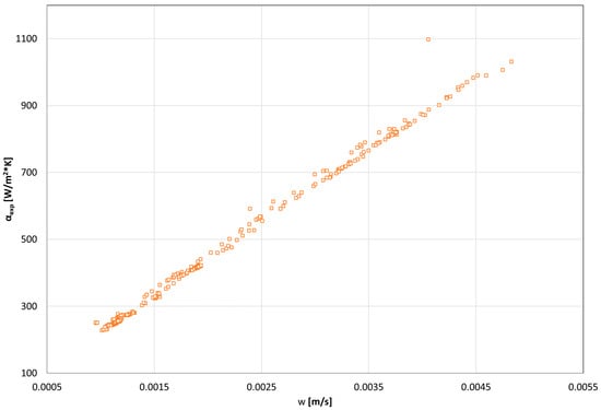
Figure 9.
The dependency of the HTC on the condensate velocity.
Research on the condensation of HFE 7000/HFE 7100 refrigerants was conducted in a compact heat exchanger [30]. The paper presents a dimensionless dependence on determining the value of the HTC during condensation of the refrigerant on a horizontal bundle of pipes in the form, as follows:
where Ga is the Galileo number
and K is the condensation phase transmission describing number [34]
Since this study presents the research results on the HFE7100 refrigerant condensation process in a heat exchanger made by 3D printing, it was decided to check the possibility of using the developed relationship (7) in the description of the research results presented in this study. Figure 10 compares the Nusselt number values’ experimental data with the results of calculations using Formula (7). A good agreement in the range of ±25% was obtained. This allows for the recommendation of the use of the above relationship in engineering calculations to design compact heat exchangers.
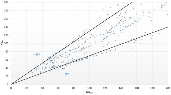
Figure 10.
Comparison of the Nusselt number values for the results of experimental studies with the results of calculations according to dependence (7).
To verify the scope of applicability of the existing model describing the local Nusselt number during refrigerant condensation on minichannels, the residual analysis method, using the MAPE error (mean absolute percentage error), was used
Expression, Nuth, is the Nusselt number determined from the correlation calculations of individual authors, whereas Nuexp is the Nusselt number value determined experimentally, and n is the number of measurements made. Over 68% of the entire data are in the range of ±25% (Figure 11).
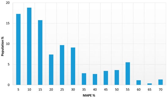
Figure 11.
Mean absolute percentage error distribution for Nusselt number.
4. Conclusions
Based on the literature review, large gaps were found in the publications on heat exchange in heat exchangers made using additive methods. Most of the presented results refer to heat exchangers printed from polymers and other materials with low thermal conductivity. There are several publications describing research on 3D-printed metal heat exchangers. Due to the current state of knowledge in this field, it was decided to conduct experimental studies on a compact shell-and-tube heat exchanger made in metal 3D printing technology, in which the heating medium was the condensing refrigerant HFE7100, and the cooling medium was mPCM slurry and water (as reference fluid). The tests were performed in a certain range of thermal and flow parameter changes, as follows: G = 10–450 [kg m−2 s−1], q = 2000–25,000 [W m−2], and ts = 30–40 [°C]. Based on the results of the experimental research, thermal and flow characteristics of the heat exchanger were obtained in the form of the dependence of the heat flux, HTC, and the overall heat exchange coefficient on the temperature of the cooling medium. The condensate film thickness and its flow rate were also determined. According to the results of the analyses obtained, the following were found:
- The test results confirmed that the HTC value has a slight dependence on the heat flux density during refrigerant condensation. The heat exchange coefficient gradually increases with the heat flux density. However, a four-fold increase in q causes only a 10% increase in the value of the α on the cooled surface.
- The thermal power strongly depends on the type of coolant. The highest values were observed during cooling with a 10% mPCM slurry. The lowest heat flux values were noted for water cooling. It was also found that the heat flux increases during the PCM phase transition. The influence of mass share on the value of heat flux was also observed. The higher the mass fraction of mPCM in the mixture, the greater the heat flux.
- The OHTC also depends on the type of coolant. The lowest values were observed during water cooling. The highest overall heat exchange coefficient values were noted during the 10% mPCM slurry cooling. It was also found that the overall heat exchange coefficient increased during the PCM phase transition. For the 10% mPCM, there was an over 11% increase in the overall heat exchange coefficient. The influence of mass share on the value of heat flux was also observed. The higher the mass fraction of mPCM in the mixture, the greater the heat flux.
- The refrigerant’s HTC values depend on the thickness of the condensate film. The HTC values decrease significantly between 0.00003 and 0.001 m of the thickness of the condensate film.
- The value of the HTC is proportional to the increase in the velocity of the condensate, which results from the laminar nature of the condensate flow. An increase in the condensate velocity reduces the thickness of the condensate layer, which reduces the value of thermal resistance and increases the value of the HTC.
- The authors demonstrated the possibility of using Equation (9) to determine the value of the HTC during condensation of the refrigerant on the surface of a smooth pipe bundle inside a compact heat exchanger made by 3D printing. This equation can be used in compact heat exchanger projects.
- The research results indicate the need to conduct further experimental research on the heat exchange enhancement regarding the impact of process parameters such as Δtlog, or the mass fraction of the mPCM in the cooling liquid, and the internal geometry of 3D-printed mini heat exchangers.
- The future direction of the experimental research is to determine the effect of the state of matter of the phase change material mixture on the flow resistance in compact heat exchangers, and the impact of deposits of cooling mixtures on the operating parameters of heat exchangers.
Author Contributions
Methodology, M.K.; Validation, T.B.; Investigation, M.K. and K.D.; Resources, M.K.; Data curation, T.B.; Writing—review & editing, K.D. All authors have read and agreed to the published version of the manuscript.
Funding
This research received no external funding.
Data Availability Statement
The data presented in this study are available on request from the corresponding author. The data are not publicly available due to privacy.
Conflicts of Interest
The authors declare no conflict of interest.
Nomenclature
| A | area (m2) |
| d | diameter (m) |
| G | mass flux density (kg·m−2·s−1); |
| h | enthalpy (kJ·kg−1) |
| L | length (m) |
| ṁ | mass flow rate (kg·h−1) |
| Nu | Nusselt number |
| q | heat flux density (W·m−2) |
| Q | heat flux (W) |
| r | heat of condensation/evaporation (J·k−1) |
| Re | Reynolds number |
| t | temperature (°C) |
| T | temperature (K) |
| Index | |
| c | condensation, coolant |
| exp | experiment |
| e | external |
| f | fluid |
| h | hydraulic |
| i | internal |
| l | liquid |
| r | heat of phase change |
| th | theoretical |
| w | wall, water |
| Greek symbols | |
| α | heat exchange coefficient (W·m−2∙K−1) |
| Δ | difference |
| λ | thermal conductivity (W·m−1·K−1) |
| ν | kinematic viscosity (m−2 s−1) |
| Acronyms | |
| HE | heat exchanger |
| HTC | heat exchange coefficient |
| OHTC | Overall heat exchange coefficient |
| mPCM | microencapsulated phase change material |
References
- Tang, W.; Zou, C.; Zhou, H.; Zhang, L.; Zeng, Y.; Sun, L.; Zhao, Y.; Yan, M.; Fu, J.; Hu, J.; et al. A novel convective heat transfer enhancement method based on precise control of Gyroid-type TPMS lattice structure. Appl. Therm. Eng. 2023, 230, 120797. [Google Scholar] [CrossRef]
- Reynolds, B.W.; Fee, C.J.; Morison, K.R.; Holland, D.J. Characterisation of Heat Transfer within 3D Printed TPMS Heat Exchangers. Int. J. Heat Mass Transf. 2023, 212, 124264. [Google Scholar] [CrossRef]
- Wu, Y.; Zhi, C.; Wang, Z.; Chen, Y.; Wang, C.; Chen, Q.; Tan, G.; Ming, T. Enhanced thermal and mechanical performance of 3D architected micro-channel heat exchangers. Heliyon 2023, 9, e13902. [Google Scholar] [CrossRef]
- Haertel, J.H.K.; Nellis, G.F. A fully developed flow thermofluid model for topology optimization of 3D-printed air-cooled heat exchangers. Appl. Therm. Eng. 2017, 119, 3–24. [Google Scholar] [CrossRef]
- Ahmadi, B.; Cesarano, J.; Nawaz, K.; Ninos, N.; Bigham, S. A high-performance lung-inspired ceramic 3D-printed heat exchanger for high-temperature energy-efficient systems. Appl. Therm. Eng. 2023, 219, 119378. [Google Scholar] [CrossRef]
- Puttur, U.; Ahmadi, M.; Ahmadi, B.; Bigham, S. A novel lung-inspired 3D-printed desiccant-coated heat exchanger for high-performance humidity management in buildings. Energy Convers. Manag. 2022, 252, 115074. [Google Scholar] [CrossRef]
- Kus, K.; Wójcik, M.; Malecha, Z.; Rogala, Z. Numerical and experimental investigation of the gyroid heat exchanger. Int. J. Heat Mass Transf. 2024, 231, 125882, ISSN 0017-9310. [Google Scholar] [CrossRef]
- Pracht, S.; Will, J.; Klöppel, S.; Funke, T.; Quack, H.; Haberstroh, C. Experimental and numerical study of a 3D-printed aluminium cryogenic heat exchanger for compact Brayton refrigerators. Cryogenics 2022, 123, 103418. [Google Scholar] [CrossRef]
- Dixit, T.; Al-Hajri, E.; Paul, M.C.; Nithiarasu, P.; Kumar, S. High performance, microarchitected, compact heat exchanger enabled by 3D printing. Appl. Therm. Eng. 2022, 210, 118339. [Google Scholar] [CrossRef]
- Shin, D.; Jeon, J.; Kim, T.; Park, J.H.; Kim, S.J. Development of the thermal performance model using temperature gradient analysis for optimized design of steam surface condenser. Int. J. Heat Mass Transf. 2020, 163, 120411. [Google Scholar] [CrossRef]
- Li, Z.; Xing, W.; Sun, J.; Feng, X. Multiscale structural characteristics and Heat–Moisture properties of 3D printed building Walls: A review. Constr. Build. Mater. 2023, 365, 130102. [Google Scholar] [CrossRef]
- Ahmadi, B.; Bigham, S. Performance Evaluation of hi-k Lung-inspired 3D-printed Polymer Heat Exchangers. Appl. Therm. Eng. 2022, 204, 117993. [Google Scholar] [CrossRef]
- Wang, C.S.; Wang, E.S.; Huang, Y.J.; Liou, T.M. PIV and IRT measurements of hydrothermal performance in a U-shaped heat exchanger with 3D printed detached curved ribs. Int. J. Heat Mass Transf. 2023, 201, 123562. [Google Scholar] [CrossRef]
- Khan, H.H.; Aneesh, A.M.; Sharma, A.; Srivastava, A.; Chaudhuri, P. Thermal-hydraulic characteristics and performance of 3D wavy channel based printed circuit heat exchanger. Appl. Therm. Eng. 2015, 87, 3–528. [Google Scholar] [CrossRef]
- Aneesh, A.M.; Sharma, A.; Srivastava, A.; Vyas, K.N.; Chaudhuri, P. Thermal-hydraulic characteristics and performance of 3D straight channel based printed circuit heat exchanger. Appl. Therm. Eng. 2016, 98, 3–482. [Google Scholar] [CrossRef]
- Lowrey, S.; Hughes, C.; Sun, Z. Thermal-hydraulic performance investigation of an aluminium plate heat exchanger and a 3D-printed polymer plate heat exchanger. Appl. Therm. Eng. 2021, 194, 117060. [Google Scholar] [CrossRef]
- Bayaniahangar, R.; Okoh, I.; Nawaz, K.; Cesarano, J.; Bigham, S. Toward extreme high-temperature supercritical CO2 power cycles: Leakage characterization of ceramic 3D-printed heat exchangers. Addit. Manuf. 2022, 54, 102783. [Google Scholar] [CrossRef]
- Zhao, B.; Zhang, J.; Lian, W. Numerical Modeling of Heat Exchanger Filled with Octahedral Lattice Frame Porous Material. Aerospace 2022, 9, 238. [Google Scholar] [CrossRef]
- Kim, S.; Nam, S.H.; Kim, S.; Cho, Y.T.; Fang, N.X. Low Heat Capacity 3D Hollow Microarchitected Reactors for Thermal and Fluid Applications. Energies 2022, 15, 4073. [Google Scholar] [CrossRef]
- Dutkowski, K.; Kruzel, M.; Rokosz, K. Review of the State-of-the-Art Uses of Minimal Surfaces in Heat Transfer. Energies 2022, 15, 7994. [Google Scholar] [CrossRef]
- Zhu, Z.; Li, J.; Peng, H.; Liu, D. Nature-inspired structures applied in heat transfer enhancement and drag reduction. Micromachines 2021, 12, 656. [Google Scholar] [CrossRef] [PubMed]
- Pelanconi, M.; Zavattoni, S.; Cornolti, L.; Puragliesi, R.; Arrivabeni, E.; Ferrari, L.; Gianella, S.; Barbato, M.; Ortona, A. Application of ceramic lattice structures to design compact, high temperature heat exchangers: Material and architecture selection. Materials 2021, 14, 3225. [Google Scholar] [CrossRef] [PubMed]
- Kelava, L.; Ivić, I.; Pakai, E.; Fekete, K.; Maroti, P.; Told, R.; Ujfalusi, Z.; Garami, A. Stereolithography 3D Printing of a Heat Exchanger for Advanced Temperature Control in Wire Myography. Polymers 2022, 14, 471. [Google Scholar] [CrossRef] [PubMed]
- Wu, J.; Xu, P.; Li, L.; Li, Z.; Qi, H.; Wang, C.; Zhang, Y.; Xie, Y.; Tan, D. Multiphase dynamic interfaces and abrasive transport dynamics for abrasive flow machining in shear thickening transition states. Powder Technol. 2024, 446, 120150. [Google Scholar] [CrossRef]
- Mehendale, S.; Jacobi, A.M.; Shah, M.M. Fluid flow and heat transfer at micro- and meso-scales with application to heat exchanger design. Appl. Mech. Rev. 2000, 53, 175–193. [Google Scholar] [CrossRef]
- Kandlikar, S.G.; Grande, W.J. Evolution of Microchannel Flow Passages--Thermohydraulic Performance and Fabrication Technology. Heat Transf. Eng. 2003, 24, 3–17. [Google Scholar] [CrossRef]
- Dutkowski, K.; Kruzel, M.; Zajączkowski, B.; Białko, B. The experimental investigation of mPCM slurries density at phase change temperature. Int. J. Heat Mass Transf. 2020, 159, 3. [Google Scholar] [CrossRef]
- Dutkowski, K.; Kruzel, M.; Zajączkowski, B. Determining the Heat of Fusion and Specific Heat of Microencapsulated Phase Change Material Slurry by Thermal Delay Method. Energies 2020, 14, 3. [Google Scholar] [CrossRef]
- Dutkowski, K.; Kruzel, M. Microencapsulated PCM slurries’ dynamic viscosity experimental investigation and temperature-dependent prediction model. Int. J. Heat Mass Transf. 2019, 145, 118741. [Google Scholar] [CrossRef]
- Kruzel, M.; Bohdal, T.; Dutkowski, K.; Radchenko, M. The Effect of Microencapsulated PCM Slurry Coolant on the Efficiency of a Shell and Tube Heat Exchanger. Energies 2022, 15, 5142. [Google Scholar] [CrossRef]
- Kruzel, M.; Bohdal, T.; Dutkowski, K. External condensation of hfe 7000 and hfe 7100 refrigerants in shell and tube heat exchangers. Materials 2021, 14, 6825. [Google Scholar] [CrossRef] [PubMed]
- Dutkowski, K.; Kruzel, M.; Bohdal, T. Experimental studies of the influence of microencapsulated phase change material on thermal parameters of a flat liquid solar collector. Energies 2021, 14, 5135. [Google Scholar] [CrossRef]
- Staniszewski, B. Heat Eexchange. Theoretical Fundamentals; PWN: Warsaw, Poland, 1979. [Google Scholar]
- Madejski, J. Theory of Heat Transfer; Scientific Publishing House of the Szczecin University of Technology: Szczecin, Poland, 1998; ISBN 83-87423-47-5. (In Polish) [Google Scholar]
Disclaimer/Publisher’s Note: The statements, opinions and data contained in all publications are solely those of the individual author(s) and contributor(s) and not of MDPI and/or the editor(s). MDPI and/or the editor(s) disclaim responsibility for any injury to people or property resulting from any ideas, methods, instructions or products referred to in the content. |
© 2024 by the authors. Licensee MDPI, Basel, Switzerland. This article is an open access article distributed under the terms and conditions of the Creative Commons Attribution (CC BY) license (https://creativecommons.org/licenses/by/4.0/).