Article

Experimental Investigation on Heat Transfer in Two-Phase Closed Thermosyphon Containing Non-Condensable Gas

School of Mechatronics and Information Engineering, China University of Mining and Technology (Beijing), Beijing 100083, China
*
Author to whom correspondence should be addressed.
Energies 2024, 17(18), 4693; https://doi.org/10.3390/en17184693
Submission received: 9 August 2024 / Revised: 15 September 2024 / Accepted: 16 September 2024 / Published: 20 September 2024
(This article belongs to the Section J: Thermal Management)

Abstract

:
Given that two-phase closed thermosiphons (TPCT) are a prevalent and efficacious means of heat transfer. However, non-condensable gas (NCG) may potentially impact the heat transfer performance of the aforementioned devices. Nevertheless, the theoretical analysis of heat transfer in TPCT containing NCG is not fully comprehensive and therefore requires further supplementation by means of relevant experiments. This paper presents the development and experimental investigation of a theoretical heat transfer model for a TPCT containing NCG. The research encompasses the optimal fluid-filling ratio of R22 and R410a working fluid and the impact of NCG on heat transfer in the condenser section of TPCT. Experimental findings indicate that TPCT with R22 and R410a working fluids at a fluid-filling ratio of 60% and 50%, respectively, demonstrate excellent isotherm and heat transfer efficiency. The presence of NCG affects the condenser section heat transfer process of the vapor, leading to a 2 °C decrease in the average temperature of the condenser section of the TPCT (Tca). In comparison with the TPCT without NCG, it was observed that an increase in the mass of NCG from 0.0097 to 0.0197 mol resulted in a reduction in the effective length of the condenser section (La) and effective heat transfer rate (κ) of R22 TPCT. The decrease in La was 75.1 mm, while the decrease in κ was 15.02%. Furthermore, at the same NCG mass, the effective heat transfer rate of R410a TPCT is evidently superior to that of R22 TPCT. The NCG in the TPCT can be removed by using a check valve. Nevertheless, this will result in a reduction in the fluid-filling ratio of the TPCT. The temperature of the R410a TPCT containing 0.0197 mol NCG with a fluid-filling ratio of 50% is comparable to that observed in fluid-filling ratio of 40% after the NCG is exhausted.

1. Introduction

The two-phase closed thermosiphon (TPCT) is a gravity-assisted wickless heat pipe that employs the evaporation and condensation of the working fluid to facilitate heat transfer through an autonomous cycle. The condensate is returned to the evaporator section from the condenser section not by the capillary force, but by the condensate’s own gravity. In comparison with the traditional heat pipe, the TPCT has a small resistance to flow in the tube and a low boil-off limit, as well as a wide range of heat transfer temperatures [1,2]. TPCT is distinguished by its high heat transfer efficiency, straightforward and dependable structure, and low manufacturing cost, among other attributes. It is employed in a multitude of applications, including solar collectors, permafrost cooling, photovoltaic batteries, the dissipation of heat from electronic devices, and other systems using heat management and recovery techniques [3,4,5,6,7,8]. The primary factors influencing the heat transfer performance of the TCPT are the geometry structure (including diameter, shape, and length), types of the working fluid, non-condensable gas (NCG), fluid-filling ratio, and inclination angle [9,10,11,12]. The selection of the working fluid is contingent upon the operational temperature of the TPCT. In temperatures below 30 °C, ammonia and a range of refrigerants (including R134a, R22, and R410a) are frequently employed. Water has been demonstrated to be a viable working fluid at temperatures between 30 °C and 300 °C. At temperatures exceeding 300 °C, liquid metals and a variety of organic fluids are commonly used as working fluids [13,14]. The fluid-filling ratio of TCPT is a determining factor in the relationship between the liquid film and the liquid pool in the evaporator section. An excess or insufficiency of the fluid-filling ratio will result in a reduction in the heat transfer efficiency of TCPT [15]. Inappropriate operation during the TPCT charging process and leakage during negative pressure operation may result in the introduction of NCG. Furthermore, the chemical reaction between specific working fluids and impurities may also generate NCG, which is unable to be liquefied at room temperature and pressure. This has a significant impact on the condensation process of the working fluids in the TPCT [16].
Many previous studies have been conducted about the effect of the above factors on the thermal performance of the TPCT. A large number of studies have been dedicated to investigating the impact of efficient heat transfer on the TPCT, with a particular focus on types of working fluids, the fluid-filling ratio, and the inclination angle. The three commonly used working fluids in TPCT for waste heat recovery applications are water, glycol, and ethanol. The thermal performance of water is superior at low cooling water flow rates when the waste heat is low. However, glycol is a more efficient working fluid at high flow rates, while ethanol is suitable for waste heat recovery scenarios where there is a large source of waste heat. Furthermore, underfilling of the working fluid can result in drying out at the bottom of the evaporator section of the TCPT, while overfilling can lead to poor isothermal performance of the TPCT [17,18]. The impact of fluid-filling ratio and inclination angle on the heat transfer coefficient of TPCT was elucidated by Kim et al. [11]. It was observed that the influence of the inclination angle on the heat transfer coefficient of condensation is more pronounced than that on the heat transfer coefficient of boiling, particularly at a low fluid-filling ratio of 0.25. In addition, Wu et al. [10] presents an equation that describes the variation in actual heating area with respect to the inclination angle. Additionally, a model for the areal thermal resistance of a thermosyphon is proposed, based on an analysis of the primary influencing mechanisms of the inclination angle on the heat transfer process. The available nucleate boiling correlations, together with their combination with a filmwise evaporation correlation and filmwise model containing liquid entrainment effects in the condenser section by Jafari et al. [19], were able to accurately predict the condensation and evaporation heat transfer processes in TPCT with different fluid-filling ratios. The experimental results provided confirmation of the validity of this approach. The following studies investigate the impact of geometry structure on the heat transfer performance of TPCT. In an experimental investigation, Lin et al. [20] examined the steady-state and transient characteristics of an ultra-long thermosiphon with a length of 48 m and an inner diameter of 40.3 mm. Ozbas et al. [21] fabricated three TPCTs with varying internal structures and investigated the heat transfer performance at different inclinations. In a series of experiments, Alammar et al. [22] investigated the impact of internal surface roughness on the heat transfer performance of TPCT. In addition to the above influences, the operation of TPCT is also significantly affected by NCG.
In comparison to the working fluid, working condition, and geometric structure, NCG exerts a more significant influence on the operation of TPCT. The principal reason for this is that NCG is a gaseous substance and cannot be liquefied at normal temperature and pressure, which renders the condensation process more complex. In recent years, numerous researchers have investigated the impact of NCG on vapor condensation. The primary focus of the study conducted by Huang et al. [23] was the physical models of heat transfer for filmwise condensation (FWC) with NCG. Kumar et al. [24] presented a CFD model for predicting the condensation of vapor on walls in the presence of non-condensable gases. Zhang et al. [25] established a new model for filmwise condensation heat transfer that was developed using a similarity-based solution. In addition, they derived and calculated the expression of gas–liquid interfacial temperature, film thickness, and the heat transfer coefficient. Bérut et al. [26] combined hydrodynamic and axial mass diffusion phenomena with two-dimensional heat conduction in the wall to develop a numerical model of filmwise condensation inside a vertical tube in the presence of NCG. In addition, Yuan et al. [14] conducted an analysis of the thermal performance of TPCT with NCG under a range of conditions, including different evaporator section temperatures, varying NCG masses, and different inclination angles. This analysis employed a combination of experimental, theoretical heat transfer efficiency models, and CFD models to investigate the impact of these variables on key performance metrics such as tube wall temperature, heat transfer efficiency, thermal resistance, and NCG phase distribution under steady state. For loop heat pipe (LHP) with NCG, He et al. [27] conducted an experimental investigation to assess the impact of NCG on the operational performance of ammonia stainless steel LHP. Nitrogen was selected as the NCG, and the influence of NCG on LHP steady-state operation under varying NCG inventory, evaporator heat load, heat load cycle times, and radiator temperature were examined. Variable conductance heat pipes (VCHP) have a gas reservoir that charges NCG. Based on the theoretical design and analysis, Guo et al. [28] conducted an experimental study on the influence of multiple parameters on the thermal performance of VCHP.
According to the literature review above, both the fluid-filling ratio of the working fluid and NCG inside TPCT impact the thermal performance of TPCT. However, few researchers have performed an analysis of NCG’s influence on heat transfer in the condenser section at the optimum fluid-filling ratio. In addition, a comprehensive and effective methodology for the removal of NCG from TPCT remains to be elucidated. Therefore, in this paper, firstly, the heat transfer model of the condenser section in a two-phase loop thermosyphon with non-condensable gas was established. Secondly, the temperature distribution of TPCT with different fluid-filling ratios was studied through experiments. Finally, the effect of NCG with different masses on the heat transfer in the condenser section of TPCT was studied through experiments, and an efficacious methodology for the discharge of NCG was analyzed.
To gain further insight into the heat transfer performance of TPCT containing NCG, Section 2 of this work presents the working principle of TPCT containing NCG, the apparatus employed in experimentation, and an analysis of experimental uncertainty assessment. Section 3 comprises an exposition of the experimental methods and theoretical reasoning pertaining to the heat transfer of TPCT containing NCG. Section 4 presents an analysis and discussion of the experimental results. Section 5 provides a summary of the aforementioned research content.

2. Experimental Setup

2.1. Working Principle

The TPCT containing NCG is shown in Figure 1 When TPCT is in a non-working state (Figure 1a), the density of NCG is low and it is dispersed throughout the upper portion of the heat pipe in the form of a gas. This gas exhibits higher critical pressure and lower critical temperature characteristics. When the TPCT is in a working state (Figure 1b), the internal working fluid is heated and boiled to produce an upward-moving vapor, with the NCG gathering at the top of the condenser section of the heat pipe under vapor pressure. The vapor must pass through the NCG accumulation area, reaching the surface of the condensate liquid film, which results in a reduction of the local condensing heat transfer efficiency of the vapor. It can be reasonably deduced that the overall heat transfer efficiency of TPCT will be affected by the non-condensable gas.

2.2. Experimental Equipment

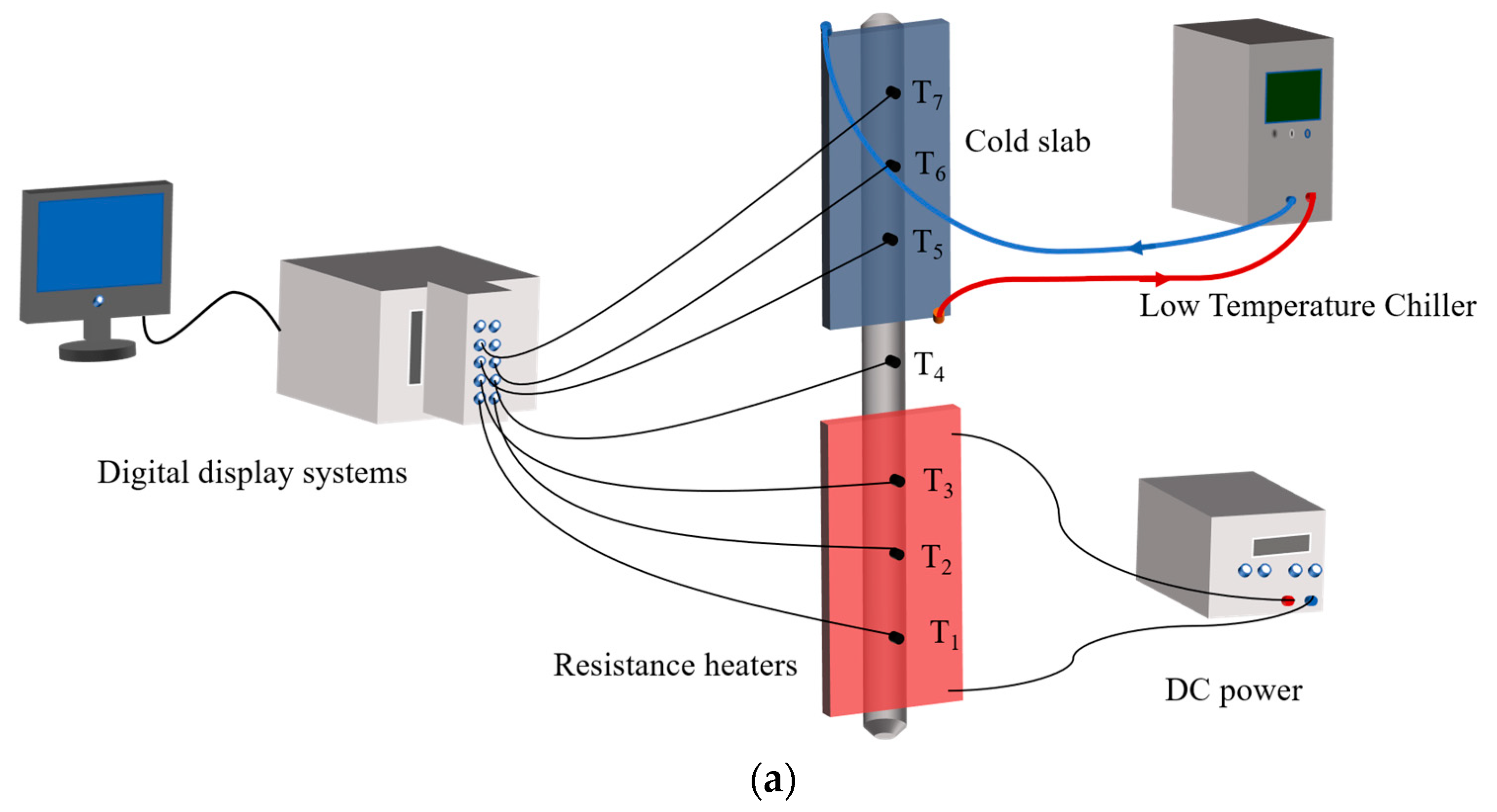
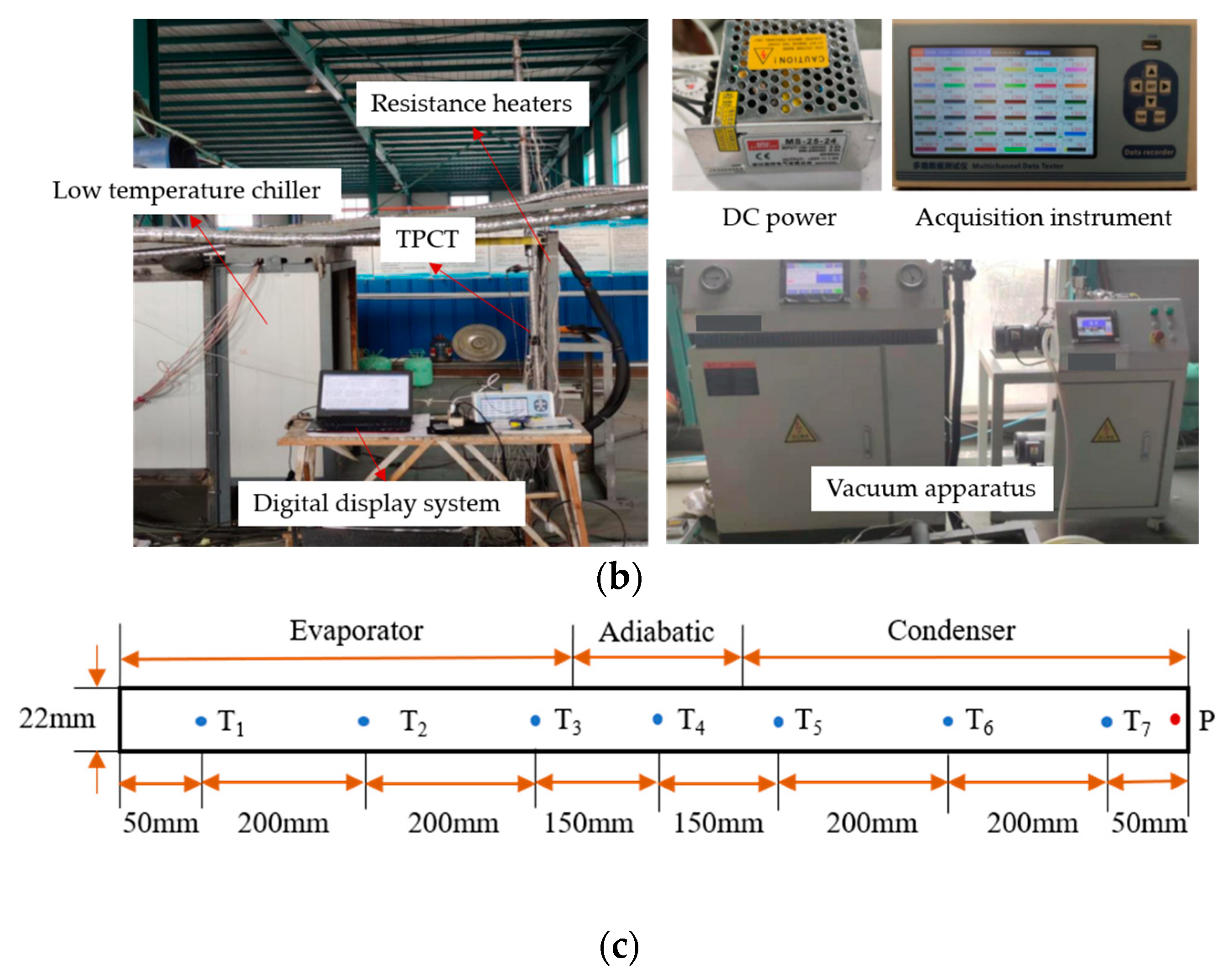
As shown in Figure 2a, the experimental apparatus constructed in this study primarily comprises TPCT to be evaluated, resistance heaters, cold slab, DC power, low-temperature chiller, and digital display systems. The experimental equipment is shown in Figure 2b. The TPCT is positioned vertically at an angle of 90°, with the evaporator section mounted on the resistance heaters. The latter is controlled by a regulated DC power, with the resulting uncertainty in the calculated value based on the uncertainty of the voltage and current at approximately 4.2%. The condenser section is situated on the cold slab of the low-temperature chiller for the purpose of cooling, and the contact surface is coated with a high-thermal-conductivity grease. The low-temperature chiller is capable of being adjusted within a range of 5~35 °C, with a maintained temperature stability of 0.1 °C. The pipe connecting the chiller and the cold slab, as well as the adiabatic section of the TPCT, are covered with a thermal insulation layer on the exterior. The digital display systems comprise a personal computer (PC) and an acquisition instrument. The vacuum apparatus is capable of extracting the air within the TPCT and regulating the vacuum degree. The TPCT model is illustrated in Figure 2c. The TPCT pipe is constructed with 304 stainless steel wall material, which has a thickness of 3.2 mm. The heat pipe has a structural dimension of 1200 mm, with an inner diameter of 22 mm. Specifically, the evaporator section (Le) measures 500 mm, the condenser section (Lc) measures 500 mm, and the adiabatic section (Lad) measures 200 mm. Seven temperature-measuring points are distributed from T1 to T7, and pressure-measuring points are also included.

2.3. Experimental Uncertainty Assessment

As some of the discrepancies observed in the experimental data were attributable to the equipment employed, an error analysis was conducted to provide a more precise assessment of the heat transfer performance of the TPCT. Table 1 shows the accuracy of each experimental equipment in this investigation. According to the law of error propagation, the uncertainties of heat flux and heat transfer coefficient have been calculated as the follows [9]:
q q = Q Q 2 + A A 2
h h = q q 2 + T T 2
In this investigation, when the heating power is 30 W, the maximum error of heat flux and heat transfer coefficient are 4.6%.

3. Experimental Method and Calculation

3.1. Experimental Condition

In this study, two distinct working fluids, R22 and R410a, whose characteristic properties are shown in Table 2, with fluid-filling ratios of 40%, 50%, 60%, and 70%, were introduced into the TPCT, resulting in the formation of eight unique heat pipe. Resistance heaters with a fixed power of 30 W were installed in the evaporator section for the purpose of heating, and a low-temperature chiller was employed for the provision of constant temperature cooling in the condenser section. The temperature was set to 10 °C, and each heat pipe was operated continuously for a period of 20 min. In order to ensure the representativeness of the measured temperature, the average temperature of the seven measuring points was calculated within the aforementioned 20 min period. According to the measured experimental data, the fluid-filling ratio of R22 and R410a TPCTs with the best heat transfer performance and isothermal property was determined.
Following the determination of the optimal fluid-filling ratio for the two working fluids (R22 and R410a), the vacuum degree within the heat pipe was set with the vacuum apparatus, and the vacuum degree of TPCT was respectively set to 101 kPa, 50 kPa, and 0.005 kPa. At a vacuum degree of 101 kPa, the tube contained a significant amount of air. At a vacuum degree of 50 kPa, approximately half of the air in the tube was removed. At a vacuum degree of 0.005 kPa, the remaining air content in the tube was essentially negligible, reaching the ultimate vacuum state. Consequently, three groups of TPCT with varying NCG contents were generated. The NCG was in the form of air, and the masses were 0 mol, 0.0097 mol, and 0.0197 mol, respectively. To investigate the impact of NCG on the heat transfer of TPCT, the experiment was continued for 20 min under the previously established experimental parameters. Furthermore, the mean values of the pressure within the heat pipe and the temperature at the measuring point within the condenser section were recorded at one-minute intervals.
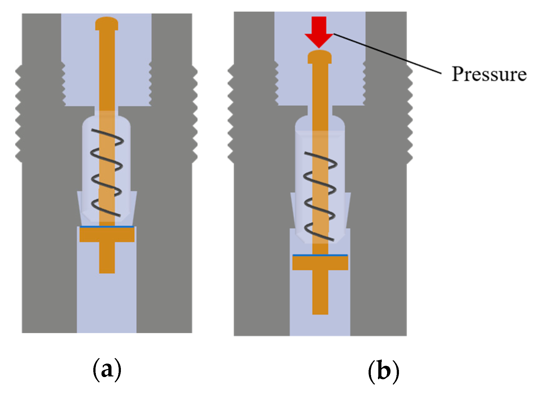
In addition to the aforementioned experimental studies, an investigation was conducted to ascertain an effective method of removing NCG from TPCT. This involved setting up an R410a TPCT containing an NCG mass of 0.0197 mol and welding a check valve at the top of the condenser section. The principal component of the check valve is the valve core, which can be actuated by pressure to open the valve. When the pressure is released, the spring return in the valve core causes the valve to close immediately. Figure 3a depicts the closed state, while Figure 3b illustrates the open state. After 20 min of operation of the heat pipe, the check valve was opened and the NCG was discharged inside the heat pipe. This process took 1–2 s to complete. The procedure was then continued for a further 10 min, during which the pressure and temperature at a measuring point in the condenser section were recorded at one-minute intervals.

3.2. Heat Transfer Analysis

Figure 4 illustrates the internal components of TPCT containing NCG under steady-state conditions. The following assumptions are made in this analysis [30]:
  • The heat pipe operates in a steady state.
  • A discrete interface is observed between the NCG and the vapor, which effectively demarcates the two phases.
  • The NCG and vaporous substances are in accordance with the ideal gas law.
  • The axial heat conduction along the tube wall is disregarded, and the total axial pressure is assumed to be equal.
The NCG exerts an influence on the condenser section of the TPCT, and the heat transfer formula for condenser section is as follows [31]:
Q = hA L a ( T ca     T c )
where Q is the heat transfer rate, h is the surface heat transfer coefficient, A is the cross-sectional area of TPCT, La is the effective length of the condenser section, Tca is the average operating temperature of the condenser section, and Tc is the average temperature of the cooling water.
In order to determine the effective condenser section length, La, it is necessary to ensure that the molar mass of the NCG remains constant for a given TPCT, irrespective of the operating conditions. In the case of an ideal gas mixture, the molar mass, n, of NCG present in the heat pipe can be calculated as follows:
n = P g ( L c     L a ) A R T g
where Pg is the pressure of the NCG, Lc is the total length of the condenser section, R is the gas constant, and Tg is the temperature of the NCG.
The mass of NCG in the initial and stable states remains constant. Furthermore, the NCG within the heat pipe can be described in accordance with the ideal gas equation of state [32]:
P g 0 V g 0 T g 0 = P g 1 V g 1 T g 1
where Pg0 is the NCG pressure under the initial state, Vg0 is the NCG volume under the initial state, Tg0 is the NCG temperature under the initial state, Pg1 is the NCG pressure under the stable state, Vg1 is the NCG volume under the stable state, and Tg1 is the NCG temperature under the stable state.
The thermodynamic pressure equilibrium is satisfied between the vapor region and the NCG region [33]:
P va = P g 1
The relationship between the effective condenser section length, La, and the NCG can be expressed as follows:
L a = L c     P g 0 V g 0 T g 1 P va T g 0 A
The rate of heat transfer in the condenser section can be calculated using Formulas (3) and (7):
Q = hA ( T ca   T c ) ( L c P g 0 V g 0 T g 1 P va T g 0 A )
In the case where the NCG mass is equal to zero, La = Lc, the effective heat transfer rate of the condenser section, denoted by κ, can then be defined as follows:
κ = L a / L c = ( 1     P g 0 V g 0 T g 1 P va T g 0 A L c ) · 100 %

4. Results and Discussions

4.1. TPCT at Different Fluid-Filling Ratios

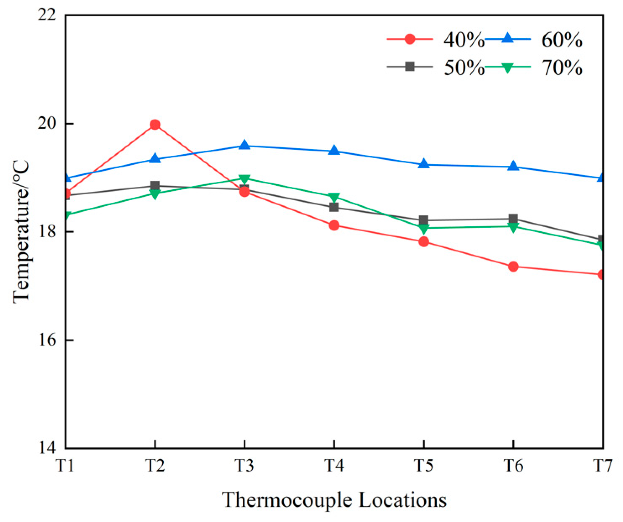
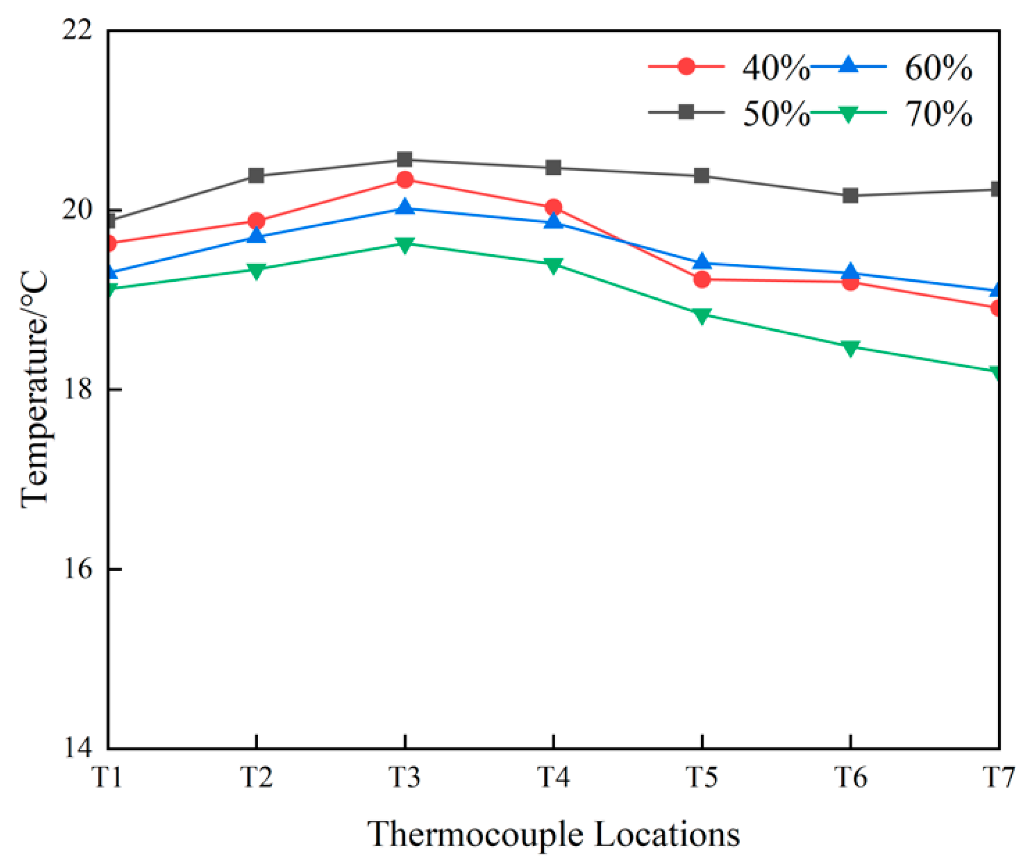
The temperature at each measuring point of R22 TPCT at different fluid-filling ratios is shown in Figure 5. At a fluid-filling ratio of 60%, the mean temperature of R22 TPCT was 19.3 °C, which is higher than that of other fluid-filling ratios. Furthermore, the temperature variance at the T1–T7 measuring points was 0.053, representing the lowest value across the four data groups. This suggests that R22 TPCT exhibits superior isotherm characteristics when the fluid-filling ratio is 60%. At a fluid-filling ratio of 70%, the quantity of liquid working fluid in the evaporator section was excessive, the rate of bubble generation was low, and the resistance to the rising process was considerable. This impeded the nuclear boiling in the evaporator section and hindered the transfer of heat within the TPCT. At a fluid-filling ratio of 40%, there was a sudden rise in the T2 temperature and a drop in the temperature of the condenser section. This phenomenon indicates a lack of comprehensive coverage of the liquid film over the evaporator section. This led to a state of dry burning at T2, accompanied by a rise in temperature and the onset of deterioration in the heat transfer capacity of the TPCT. This suggests that the quantity of the working liquid in the TPCT is currently insufficient. When the fluid-filling ratio was 60% under identical heating power conditions, there was an observed increase in both the heat flux and the rate of vaporization, as well as a notable reduction in the upward resistance. This resulted in an enhancement of the disturbance in the liquid working fluid, coupled with an elevated heat transfer coefficient within the evaporator section of the heat pipe. Moreover, the liquid film could envelop the evaporator section and be in continuity with the liquid pool, thus preventing the evaporator section from undergoing dry burning.
Figure 6 illustrates the temperature of each measuring point of R410a TPCT under different fluid-filling ratios. It can be observed that the temperature variation trend under different fluid-filling ratios is essentially analogous to that of R22. At a fluid-filling ratio of 50%, the mean temperature of R410a TPCT was 20.3 °C, which was higher than that of other fluid-filling ratios. Furthermore, the temperature variance at the T1-T7 measuring points was 0.051, representing the lowest value across the four data groups. This suggests that R410a TPCT exhibited superior isotherm characteristics when the fluid-filling ratio was 50%. In comparison to the R22 TPCT, the mean temperature of the R410a TPCT was 1 °C higher and the temperature variance was lower. Therefore, working fluid R410a could achieve a better heat transfer effect with a lower fluid-filling ratio than working fluid R22.

4.2. TPCT at Different NCG Mass

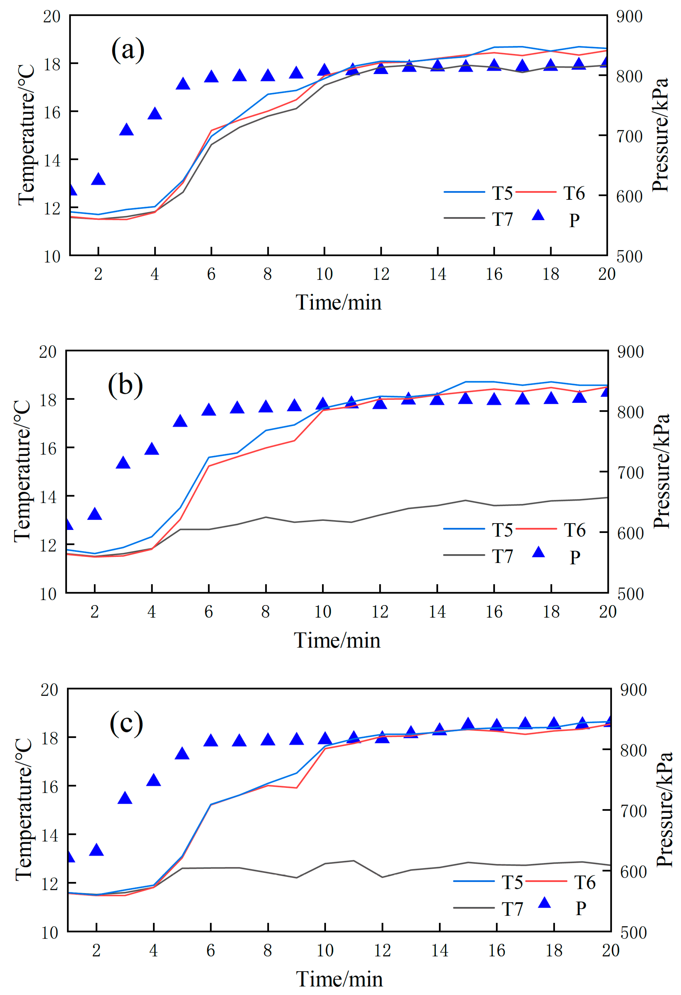
The temperature and pressure changes in the condenser section of R22 TPCT without NCG are shown in Figure 7a. Over the course of 12 min, with the continuous input of heat, the temperature of the measuring points T5, T6, and T7 in the condenser section exhibited a gradual increase. Following a 12 min period, the temperature of each measuring point reached a state of stability, with a temperature differential of 0.5 °C between T7, situated at the upper end of the condenser section, and T5, located at the lower end. At this juncture, the internal pressure of TPCT during steady operation was approximately 813.5 kPa. As illustrated in Figure 7b, the measuring point of R22 TPCT containing 0.0097 mol NCG exhibits a notable temperature differential. In comparison to TPCT without NCG, the temperature of T7 under steady-state operation was reduced by 5 °C, with the internal pressure of TPCT under steady-state operation being approximately 818.2 kPa. As evidenced by Formulas (7) and (9), the effective length of the condenser section La at this juncture is 423.5 mm, and the effective heat transfer rate κ is 84.7%. As illustrated in Figure 7c, when the NCG mass is 0.0197 mol, the temperature differential between measuring points T7, T5, and T6 in the condenser section reaches 7 °C. During steady operation, the internal pressure of TPCT was approximately 833.2 kPa, the effective length of the condenser section La was 348.4 mm, and the effective heat transfer rate κ was 69.68%. A rise in the mass of NCG from 0.0097 mol to 0.0197 mol was observed to result in a reduction in the effective length of the condenser section and effective heat transfer rate of R22 TPCT, with a decrease of 75.1 mm and 15.02%, respectively.
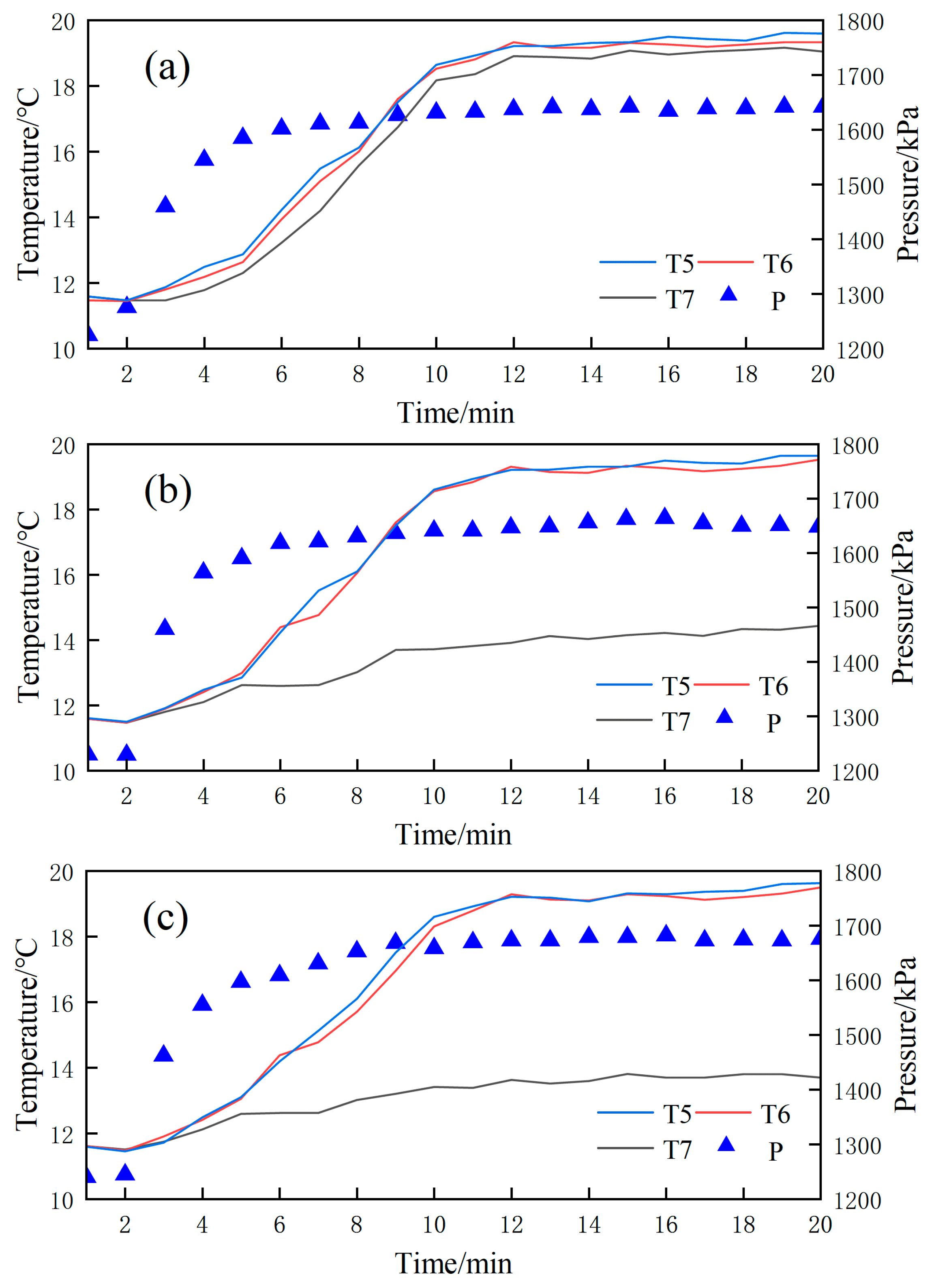
The temperature and pressure change of the condenser section of R410a TPCT without NCG are illustrated in Figure 8a. In comparison with the working fluid R22, the temperature variation trend observed at each measuring point within the condenser section was broadly similar. The higher temperature and pressure observed at each measuring point during steady operation were attributed to the large latent heat of the R410a. At this juncture, the internal pressure of the TPCT reached 1639.3 kPa. As illustrated in Figure 8b, when the NCG mass was 0.0097 mol, the temperature differential between measuring points T7 and T6 in the condenser section of R410a TPCT reached 5 °C, the internal pressure of TPCT during steady operation was approximately 1653.1 kPa, and the effective length of the condenser section La is 462 mm. The effective heat transfer rate κ is 92.4%. As illustrated in Figure 8c, when the NCG mass is 0.0197 mol, the temperature differential between measuring points T7 and T6 in the condenser section reaches 6 °C. During steady operation, the internal pressure of TPCT is approximately 1675.1 kPa, the effective length of the condenser section La is 424.4 mm, and the effective heat transfer rate κ is 84.88%. An increase in the mass of NCG, from 0.097 mol to 0.197 mol, was accompanied by a decline in the effective length of the condenser section and effective heat transfer rate of R410a TPCT, with a respective reduction of 37.6 mm and 7.52%. Furthermore, in comparison to the R22 TPCT containing NCG, it was observed that when the NCG mass was 0.0097 mol, the effective heat transfer rate was 7.7% higher. Furthermore, when the NCG mass was 0.0197 mol, the effective heat transfer rate κ was found to be 15.2% higher. This suggests that at the same NCG mass, the effective heat transfer rate of R410a TPCT was superior to that of R22 TPCT. In addition, the greater the mass of NCG, the more pronounced this effect becomes.
In comparison to the TPCT without NCG, TPCT containing NCG revealed that the former exhibited similar temperature change characteristics at the condenser sections T5 and T6. However, the influence of NCG resulted in a smoother temperature change curve at the condenser section T7, accompanied by a larger temperature difference within the condenser section upon reaching a steady state. Furthermore, the effective length of the condenser section is observed to decrease with an increase in NCG mass, which consequently results in a reduction in the effective heat transfer rate of TPCT. It can be seen that the NCG is on the rise as a consequence of the leakage and chemical reaction of the working liquid during the TPCT operational process. This will inevitably result in the TPCT heat transfer performance failing to meet the required standards, or even leading to a complete failure. A thorough investigation and analysis of this peculiarity is of paramount importance to identify an efficient and effective approach to eliminating NCG accumulation at the top of TPCT, thereby ensuring the stable and uninterrupted operation of TPCT.

4.3. TPCT Discharged NCG by Check Valve

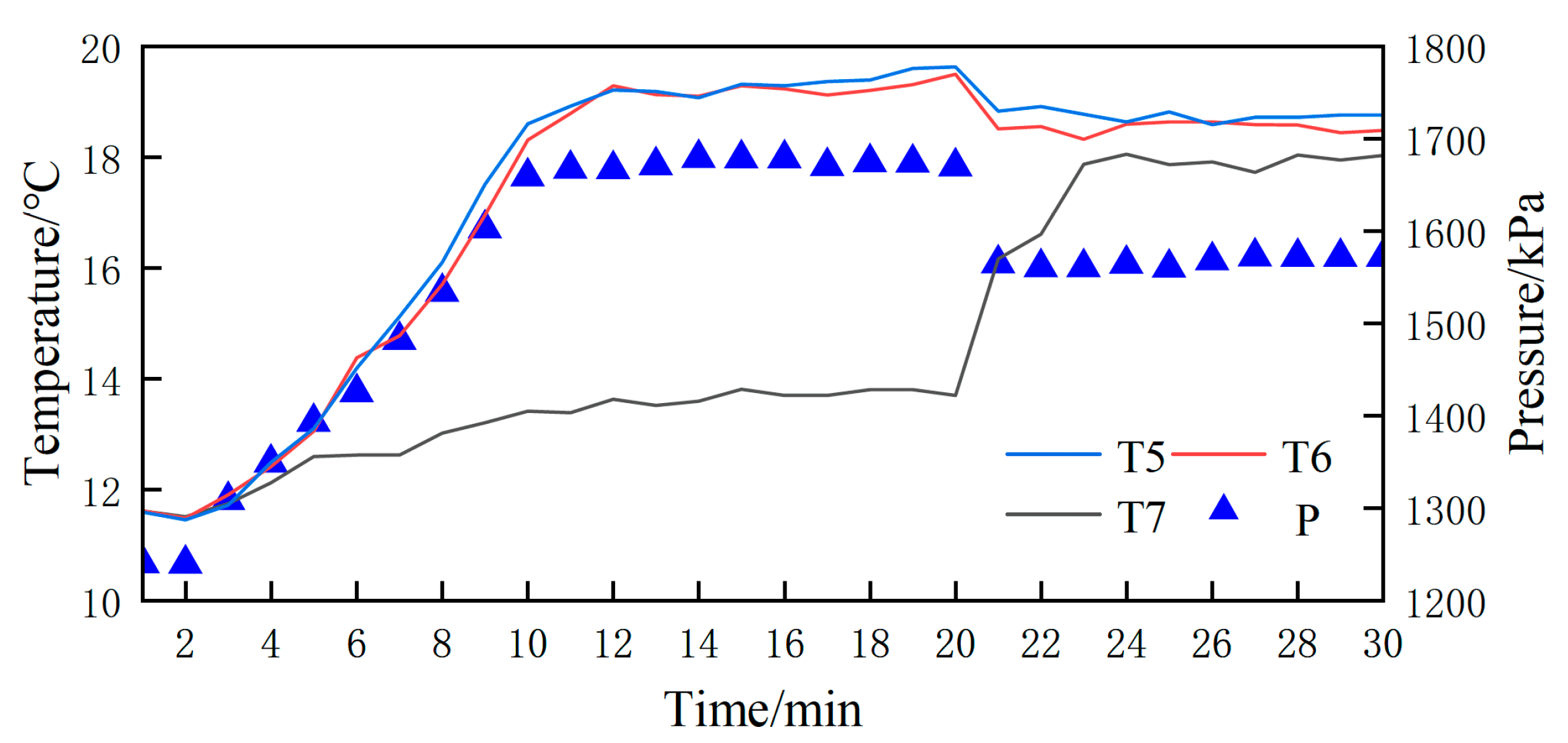
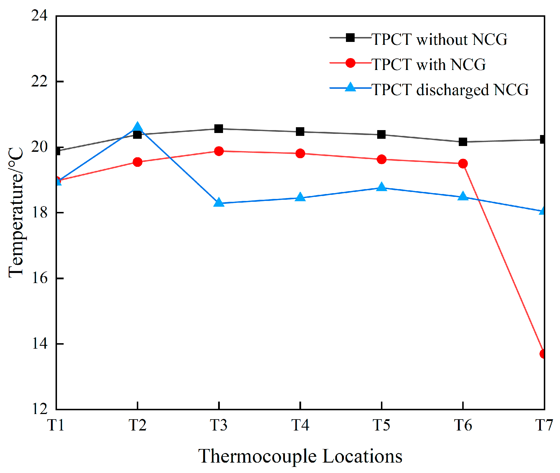
Figure 9 illustrates the temperature and pressure change in the condenser section of the R410a TPCT discharged NCG by the check valve. It can be observed that following the venting treatment for a period of 20 min, a decrease in pressure within the heat pipe was evident, with a reduction from approximately 1670 kPa under the preceding steady-state condition to approximately 1570 kPa. The temperature of measuring points T5 and T6 in the condenser section exhibited a decrease of approximately 1 °C, whereas the temperature of measuring point T7 demonstrated a rapid increase and subsequently attained a final equilibrium value of approximately 18 °C. In the stable state, the temperature difference between the three measuring points (T5, T6, and T7) was less than 1 °C. As illustrated in Figure 10, the TPCT condenser section exhibits a notable improvement in isothermal properties following the discharge of NCG, indicating that the NCG has been effectively discharged. Concurrently, the temperature of the condenser section is approximately 1 °C lower than that of TPCT with NCG and approximately 2 °C lower than that of TPCT without NCG. Additionally, the temperature T2 of the evaporator section exhibits significant fluctuations. This phenomenon suggests that the liquid film over the evaporator section is not adequately covered. It indicates that the current working liquid in TPCT is insufficient. A comparative analysis of the temperature at TPCT measuring points with varying R410a fluid-filling ratios, as depicted in Figure 6, revealed a temperature distribution that closely resembles that of a 40% fluid-filling ratio. Therefore, it is speculated that a certain amount of vapor will overflow during the process of discharging NCG by the check valve, which will result in a reduction of the fluid-filling ratio of TPCT.

5. Conclusions

The TPCT of two different working fluids, R22 and R410a, was tested experimentally in this study. The optimum fluid-filling ratio of two working fluids under steady-state conditions were determined, and the heat transfer performance of a thermosiphon containing NCG was analyzed under this fluid-filling ratio. The conclusion is as follows:
(1)
The R22 TPCT with a fluid-filling ratio of 60% and the R410a TPCT with a fluid-filling ratio of 50% demonstrate favorable isothermal and heat transfer characteristics. At this juncture, the heat flux within the TPCT increases, the rate of bubble generation is high, the rising resistance is reduced, and the heat transfer coefficient of the evaporator section of the TPCT is enhanced. The liquid film and the evaporator section are continuous, thereby preventing dry burning. In addition, compared with the R22 TPCT with a fluid-filling ratio of 60%, the mean temperature of the R410a TPCT with a fluid-filling ratio of 50% is 1 °C higher and the temperature variance is lower. This suggests that the thermal performance of the working fluid R410a is superior to that of the working fluid R22.
(2)
The existence of NCG has a negative effect on the condensation heat transfer process of vapor. The accumulation of NCG at the upper portion of the TPCT condenser section results in a reduction in the average temperature Tca and a deterioration in the isotherm of the TPCT. Furthermore, it was observed that as the mass of NCG increased, the effective length La of the condenser section and the effective heat transfer rate κ also decreased when the TPCT containing NCG operated stably. It was observed that an increase in the mass of NCG from 0.0097 to 0.0197 mol resulted in a reduction in the effective length of the condenser section and effective heat transfer rate of R22 TPCT, with a decrease of 75.1 mm and 15.02%, respectively. Moreover, at the identical NCG mass, the effective heat transfer rate of R410a TPCT is demonstrably superior to that of R22 TPCT.
(3)
It is possible to discharge the NCG in TPCT by means of a check valve. Furthermore, the condenser section exhibits favorable isothermal properties after NCG is removed. Nevertheless, it should be noted that this process will result in the discharge of vapor with NCG, which will lead to a reduction in the fluid-filling ratio of TPCT. After the NCG is exhausted, a sudden change in temperature is observed within the evaporator section of the TPCT. It indicates that the current working liquid in TPCT is insufficient. The temperature of the R410a TPCT containing 0.0197 mol NCG with a fluid-filling ratio of 50% is comparable to that observed in a fluid-filling ratio of 40% after the NCG is exhausted.
It is important to note that while the method proposed in this paper is effective in discharging NCG, it has certain limitations. The discharge of vapor during the process will affect the heat transfer efficiency of TPCT. In the future, the method proposed in this paper will be employed to regulate the on-off time of the check valve through pressure sensing and control methods, with the objective of reducing the issue of vapor loss.

Author Contributions

Conceptualization, B.S. and G.M.; investigation, B.S.; methodology, B.S. and A.W.; experiment, B.S. and W.H.; data collection and analysis, B.S. and W.H.; supervision, G.M.; writing—original draft, B.S.; writing—review & editing, X.C. and J.Y. All authors have read and agreed to the published version of the manuscript.

Funding

This research was funded by China National Key Laboratory of Intelligent Coal Mining and Rock Formation Control, grant number SKLIS202409.

Data Availability Statement

The original contributions presented in the study are included in the article; further inquiries can be directed to the corresponding author.

Conflicts of Interest

The authors declare no conflicts of interest.

References

  1. Faghri, A. Heat pipes: Review, opportunities and challenges. Front. Heat Pipes 2014, 5. [Google Scholar] [CrossRef]
  2. Jafari, D.; Franco, A.; Filippeschi, S.; Di Marco, P. Two-phase closed thermosyphons: A review of studies and solar applications. Renew. Sustain. Energy Rev. 2016, 53, 575–593. [Google Scholar] [CrossRef]
  3. Sabry, M.; Lashin, A. Performance of a heat-pipe cooled concentrated photovoltaic/thermoelectric hybrid system. Energies 2023, 16, 1438. [Google Scholar] [CrossRef]
  4. Wang, G.; Bi, J.; Fan, Y.; Zhu, L.; Zhang, F.; Feng, D. Settlement characteristic of warm permafrost embankment with two-phase closed thermosyphons in Daxing’anling Mountains region. Sustainability 2022, 14, 12272. [Google Scholar] [CrossRef]
  5. Faghri, A. Heat Pipe Science and Technology; Global Digital Press: Kanpur, India, 1995. [Google Scholar]
  6. Czerwiński, G.; Wołoszyn, J. Numerical Study of a Cooling System Using Phase Change of a Refrigerant in a Thermosyphon. Energies 2021, 14, 3634. [Google Scholar] [CrossRef]
  7. Faraji, H.; Teggar, M.; Arshad, A.; Arıcı, M.; Berra, E.M.; Choukairy, K. Lattice Boltzmann simulation of natural convection heat transfer phenomenon for thermal management of multiple electronic components. Therm. Sci. Eng. Prog. 2023, 45, 102126. [Google Scholar] [CrossRef]
  8. Faraji, H.; Faraji, M.; El Alami, M.; Hariti, Y.; Arshad, A.; Hader, A.; Benkaddour, A. Cooling of recent microprocessors by the fusion of nano-enhanced phase change materials. Mater. Today Proc. 2020, 30, 865–869. [Google Scholar] [CrossRef]
  9. Chandran, M.; Elavarasan, R.M.; Neelakandan, R.B.; Subramaniam, U.; Pugazhendhi, R. Influence of Geometrical Changes in an Adiabatic Portion on the Heat Transfer Performance of a Two-Phase Closed Thermosiphon System. Energies 2021, 14, 3070. [Google Scholar] [CrossRef]
  10. Wu, Y.; Zhang, Z.; Li, W.; Xu, D. Effect of the inclination angle on the steady-state heat transfer performance of a thermosyphon. Appl. Sci. 2019, 9, 3324. [Google Scholar] [CrossRef]
  11. Kim, Y.; Shin, D.H.; Kim, J.S.; You, S.M.; Lee, J. Boiling and condensation heat transfer of inclined two-phase closed thermosyphon with various filling ratios. Appl. Therm. Eng. 2018, 145, 328–342. [Google Scholar] [CrossRef]
  12. Noie, S.H. Heat transfer characteristics of a two-phase closed thermosyphon. Appl. Therm. Eng. 2005, 25, 495–506. [Google Scholar] [CrossRef]
  13. Fadhl, B.; Wrobel, L.C.; Jouhara, H. CFD modelling of a two-phase closed thermosyphon charged with R134a and R404a. Appl. Therm. Eng. 2015, 78, 482–490. [Google Scholar] [CrossRef]
  14. Jiao, B.; Qiu, L.; Zhang, X.; Zhang, Y. Investigation on the effect of filling ratio on the steady-state heat transfer performance of a vertical two-phase closed thermosyphon. Appl. Therm. Eng. 2008, 28, 1417–1426. [Google Scholar] [CrossRef]
  15. Naresh, Y.; Balaji, C. Thermal performance of an internally finned two phase closed thermosyphon with refrigerant R134a: A combined experimental and numerical study. Int. J. Therm. Sci. 2018, 126, 281–293. [Google Scholar] [CrossRef]
  16. Yuan, J.; Wang, C.; Zhang, J.; Ling, J.; Zhou, Z.; Gao, F. Effect of non-condensable gas on thermal characteristics in two-phase closed thermosyphon. Appl. Therm. Eng. 2020, 173, 115233. [Google Scholar] [CrossRef]
  17. Gedik, E. Experimental investigation of the thermal performance of a two-phase closed thermosyphon at different operating conditions. Energy Build. 2016, 127, 1096–1107. [Google Scholar] [CrossRef]
  18. Lataoui, Z.; Jemni, A. Experimental investigation of a stainless steel two-phase closed thermosyphon. Appl. Therm. Eng. 2017, 121, 721–727. [Google Scholar] [CrossRef]
  19. Jafari, D.; Di Marco, P.; Filippeschi, S.; Franco, A. An experimental investigation on the evaporation and condensation heat transfer of two-phase closed thermosyphons. Exp. Therm. Fluid Sci. 2017, 88, 111–123. [Google Scholar] [CrossRef]
  20. Lin, T.; Quan, X.; Cheng, P. Experimental investigation of superlong two-phase closed thermosyphons for geothermal utilization. Int. J. Therm. Sci. 2022, 171, 107199. [Google Scholar] [CrossRef]
  21. Ozbas, E.; Selimli, S.; Ozkaymak, M.; Frej, A.S.S. Evaluation of internal structure modifications effect of two-phase closed thermosyphon on performance: An experimental study. Sol. Energy 2021, 224, 1326–1332. [Google Scholar] [CrossRef]
  22. Alammar, A.A.; Al-Mousawi, F.N.; Al-Dadah, R.K.; Mahmoud, S.M.; Hood, R. Enhancing thermal performance of a two-phase closed thermosyphon with an internal surface roughness. J. Clean. Prod. 2018, 185, 128–136. [Google Scholar] [CrossRef]
  23. Huang, J.; Zhang, J.; Wang, L. Review of vapor condensation heat and mass transfer in the presence of non-condensable gas. Appl. Therm. Eng. 2015, 89, 469–484. [Google Scholar] [CrossRef]
  24. Kumar, G.V.; Cammiade, L.M.F.; Kelm, S.; Prakash, K.A.; Groß, E.M.; Allelein, H.J.; Kneer, R.; Rohlfs, W. Implementation of a CFD model for wall condensation in the presence of non-condensable gas mixtures. Appl. Therm. Eng. 2021, 187, 116546. [Google Scholar] [CrossRef]
  25. Zhang, W.; Wang, S.; Lianbo, M. Analytical modeling for vapor condensation in the presence of noncondensable gas and experimental validation. J. Heat Transf. 2021, 143, 011601. [Google Scholar] [CrossRef]
  26. Bérut, E.; Lips, S.; Lefèvre, F.; Sartre, V. Effect of non-condensable gas on heat transfer within the hollow fin condenser of metallic and polymer vapor chambers. Appl. Therm. Eng. 2021, 190, 116777. [Google Scholar] [CrossRef]
  27. He, J.; Lin, G.; Bai, L.; Miao, J.; Zhang, H. Effect of non-condensable gas on the operation of a loop heat pipe. Int. J. Heat Mass Transf. 2014, 70, 449–462. [Google Scholar] [CrossRef]
  28. Guo, Y.; Liu, C.; Pan, H.; Lyu, W.; Zhang, H.; Lin, G.; Miao, J. Experimental investigation and multiparameter analysis of variable conductance heat pipes. Appl. Therm. Eng. 2022, 202, 117589. [Google Scholar] [CrossRef]
  29. Lemmon, E.W.; Huber, M.L.; McLinden, M.O. NIST reference fluid thermodynamic and transport properties–REFPROP. NIST Stand. Ref. Database 2002, 23, v7. [Google Scholar]
  30. Marcus, B.D. Theory and Design of Variable Conductance Heat Pipes; NASA: Washington, DC, USA, 1972. [Google Scholar]
  31. Huang, C.-N.; Lee, K.-L.; Tarau, C.; Kamotani, Y.; Kharangate, C.R. Computational fluid dynamics model for a variable conductance thermosyphon. Case Stud. Therm. Eng. 2021, 25, 100960. [Google Scholar] [CrossRef]
  32. Shi, C.; Wang, Y.; Liao, Q.; Yang, Y. Analysis and application of variable conductance heat pipe air preheater. J. Therm. Sci. 2011, 20, 248–253. [Google Scholar] [CrossRef]
  33. Lee, K.-L.; Kadambi, J.R.; Kamotani, Y. The influence of non-condensable gas on an integral planar heat pipe radiators for space applications. Int. J. Heat Mass Transf. 2017, 110, 496–505. [Google Scholar] [CrossRef]
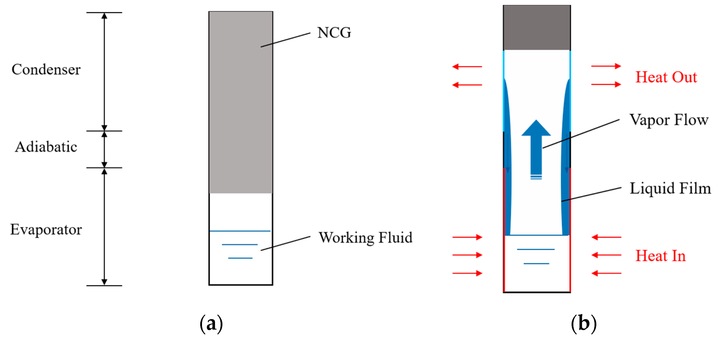
Figure 1. Two-phase loop thermosyphon containing non-condensable gas. (a) Non-working state; (b) working state.
Energies 17 04693 g001
Figure 2. Experimental system diagram. (a) Schematic diagram of the experimental system; (b) image of the experimental equipment; (c) dimensions and thermocouples’ positions.
Energies 17 04693 g002aEnergies 17 04693 g002b
Figure 3. Check valve. (a) Closed state; (b) open state.
Energies 17 04693 g003
Figure 4. The schematic structure of TPCT containing NCG.
Energies 17 04693 g004
Figure 5. Temperature distribution of R22 TPCT at different fluid-filling ratios.
Energies 17 04693 g005
Figure 6. Temperature distribution of R410a TPCT at different fluid-filling ratios.
Energies 17 04693 g006
Figure 7. Temperature pressure change of R22 TPCT at different NCG mass. (a) 0 mal NCG; (b) 0.0097 mal NCG; (c) 0.0197 mal NCG.
Energies 17 04693 g007
Figure 8. Temperature pressure change of R410a TPCT at different NCG mass. (a) 0 mal NCG; (b) 0.0097 mal NCG; (c) 0.0197 mal NCG.
Energies 17 04693 g008
Figure 9. Temperature pressure change of R410a TPCT by check valve discharged NCG.
Energies 17 04693 g009
Figure 10. Temperature distribution of R410a TPCT at different NCG states.
Energies 17 04693 g010
Table 1. Errors of experimental equipment.
Experimental EquipmentRangePrecision
Low-temperature chiller5~35 °C±0.1 °C
DC power0~36 V, 0~10 A±0.5%
Vacuum apparatus0.001~101 kPa±1%
Pressure sensor0~4 MPa±0.2%
Thermocouple−200~350 °C±0.1 °C
Table 2. Characteristic properties of R22 and R410a [29].
PropertiesR22R410a
Molecular weight (g/mol)86.4772.59
Boiling point at 1 atm (°C)−40.81−51.53
Critical temperature (°C)96.1670.46
Critical pressure (kPa)49904770
Latent heat of vaporization at boiling point (kJ/kg)191.3204.7
Heat capacity of liquid (kJ/kg K)1.221.62
Heat capacity of vapor at 1 atm (kJ/kg K)0.821.32
Thermal conductivity of liquid at 16 °C (W/mK)0.08750.0942
Thermal conductivity of vapor at 1 atm (W/mK)0.01060.0142
Density of liquid at 16 °C (kg/m3)1224.891101.72
Density of vapor at 1 atm (kg/m3)34.3649.5
Disclaimer/Publisher’s Note: The statements, opinions and data contained in all publications are solely those of the individual author(s) and contributor(s) and not of MDPI and/or the editor(s). MDPI and/or the editor(s) disclaim responsibility for any injury to people or property resulting from any ideas, methods, instructions or products referred to in the content.