Abstract
This paper presents the findings of the research aimed at developing computer models to determine the operating conditions in electric power systems (EPSs) feeding DC and AC railway substations. The object of the research is an EPS with a predominant traction load whose high-voltage power lines are connected to transformer and converter substations with 3 kV and 27.5 kV traction networks. The supply network includes 110 kV and 220 kV power lines. The EPS operating parameters are calculated based on the decomposition of the system into alternating and direct current segments. Calculations are performed for the fundamental frequency and high harmonic frequencies. The modeling technique is universal and can be used to determine the operating parameters and power quality indices for any configuration of an EPS and various designs of traction networks. With this technique, one can solve numerous additional problems, such as calculating the processes of ice melting in traction networks and power lines, determining electromagnetic field strengths, and assessing the heating of power line wires and catenary suspensions. The results obtained show that the voltages on the current collectors are within acceptable limits for all AC and DC electric locomotives. The levels of asymmetry on the 110 and 220 kV tires of traction substations (TP) do not exceed the normally permissible values. The values of the asymmetry coefficients for DC TP are tenths of a percent. With an increase in the size of traffic and in post-emergency conditions caused by the disconnection of communication between one of the support substations and the EPS, the asymmetry indicators on the 220 kV buses of AC substations may exceed the permissible limits. Phase-controlled reactive power sources can be used to reduce them. The analysis of the results of the determination of non-sinusoidal modes allows us to formulate the conclusion that the values of harmonic distortion go beyond the normative limits. Passive and active filters of higher harmonics can be used to normalize them. Calculations of thermal modes of traction transformers show that the temperatures of the most heated points do not exceed acceptable values.
1. Introduction
In the current stage of the electric power industry development, the importance of implementing the methods and tools to determine the operating parameters of electric power systems (EPSs) and railway power supply systems (RPSSs) is growing. This issue is addressed in numerous publications worldwide. For example, in [1], a methodology is presented with the view to calculating operating parameters of the RPSS to assess electromagnetic compatibility with adjacent systems. An analysis of the processes of reactive power compensation in RPSSs is given in [2,3]. The technology for simulation modeling of RPSSs equipped with energy storage devices in post-emergency and forced conditions is presented in [4]. The power transmitted from the external power system via the AC traction network is calculated in [5]. Approaches that take account of the energy storage devices when determining the RPSS operating parameters are proposed in [6].
The issues of modeling RPSSs when handling heavy trains are considered in [7]. A simulation model of a large-scale electrical network feeding traction substations (TSs) is described in [8]. This model offers a comprehensive analysis of the propagation processes for the phenomena such as phase unbalance, voltage dips, and others. The issues of calculating the RPSS operating parameters based on the measurement data are considered in [9]. The results of the study on the dynamic stability of the RPSS, considering the loads of the traction power supply system, are given in [10]. Generalized mathematical models of RPSSs are described in [11,12]. The problem of generating the equivalent load of a traction network (TN) is solved in [13]. The influence of RPSSs on the quality of electricity in a regional network is analyzed in [14]. The authors of [15] propose a technology for optimizing a traction substation based on an adaptive particle swarm algorithm. A method for modeling the dynamic distribution of the ground fault current in a low- and medium-speed traction power supply system is presented in [16].
A converter for a direct current (DC) RPSS, which ensures the handling of high-speed trains, is described in [17]. The modeling results for a new type of RPSS are presented in [18]. The characteristics of a short circuit in a DC traction network are discussed in [19]. The issue of ensuring adaptability of the traction power supply system during the operation of heavy trains is addressed in [20]. The influence of metro traction networks on the harmonics in the power grid is described in [21]. An approach to optimizing a traction power supply system equipped with photovoltaic modules is presented in [22,23]. The stability of a traction power system connected to a three-phase network is analyzed in [24]. The transfer capability of a DC RPSS is projected through the introduction of electricity storage devices [25]. A technology for assessing the reliability of the RPSS is proposed in [26]. A method of coordinated control of the photovoltaic system and the RPSS is described in [27]. A load analysis of a traction substation with different train schedules and substation faults is presented in [28]. Issues of stability of interaction between several vehicles and the traction network are considered in [29].
The analysis of the described publications confirms the relevance of research aimed at developing methods and tools for modeling the modes of electric networks supplying traction substations of mainline railways. They consider in detail some important aspects related to the issues of modeling and control of modes of traction power supply systems. At the same time, the main attention is paid to traction networks, and the power plant is usually presented in a simplified way. An integrated approach that takes into account all the important specific features of traction power supply systems is not presented in these works. The modeling technology providing determination of thermal modes of traction transformers is not presented. Furthermore, the works known to the authors do not address the issue of determining the operating parameters of electric power systems that supply the substations of DC and AC railways. It can be effectively solved with an approach that considers all influencing factors and is based on the methods and algorithms proposed in [30]. This approach can also be employed to solve additional problems, such as determining electromagnetic field strengths, modeling ice melting conditions, predicting thermal wear of transformer insulation, and others [31].
The applied approaches to modeling the modes of traction power supply systems are based on separate modeling of alternating and direct current systems. However, in many countries, both electric traction systems are used. At the same time, docking stations are being built to ensure the transition from one thrust system to another. In conditions of large-scale digitalization of the electric power industry of transport, methods, algorithms, software, and digital models are needed to determine the modes of electric networks supplying traction substations of direct and alternating current. The article presents the results of the development of such models.
The developed modeling technology, software and digital models can be effectively used to solve the following practical problems arising in the design and operation of electric networks supplying traction substations:
- Determination of modes and indicators of electricity quality;
- Selection of methods and means to improve the quality of electricity:
- Development of measures to improve the reliability of power supply and energy efficiency;
- Determination of the optimal load of traction transformers.
2. Methodology for Modeling the Operating Parameters of EPS Containing AC and DC Segments
The study employs the Fazonord software version 5.3.4.5-2024, which is described in detail in [27]. The software is capable of detecting unbalanced, non-sinusoidal, and limiting conditions in EPS, as well as in AC and DC RPSS, and allows the following:
- Modeling the three-phase, three-phase-single-phase, and three-phase-multiphase power systems with multi-wire power transmission lines and multi-winding transformers of any design;
- Determining the operating parameters of EPSs and RPSSs including AC and DC segments;
- Calculating the emergency processes for all types (simple and complex) unbalances in the electrical network;
- Correctly modeling the traction loads, which is especially important for EPSs with a large share of such loads;
- Identifying non-sinusoidal conditions, taking into account stationary and spatially moving sources of harmonic distortion;
- Analyzing the electromagnetic situation in the EPS and RPSS based on the determination (simultaneously with power flow calculation) of the strength of electromagnetic fields created by multi-wire power lines and induced voltages on adjacent lines of power transmission and communication and pipelines.
The software version 5.3.4.5-2024 allows modeling active components of electric power system that are built using smart grid technologies. These components include distributed generation plants, FACTS devices, self-compensating power lines, gas-insulated and cryogenic power lines, phase shifters, current limiters, controlled devices to eliminate unbalance, active filters for high harmonics, and others [27,28,29,32].
The operating parameters of the RPSS, which contains AC and DC subsystems, are determined using an approach which is based on the principles of diakoptics and takes into account their mutual influence in a comprehensive manner. The modeling algorithm includes the following steps:
- Calculate the AC network operating parameters in the absence of traction loads and calculate voltages at the input of converter units. Based on them, find the potentials of the nodes on the DC side.
- Determine equivalent resistances of traction substation. The DC segment includes EMF sources, contact networks and rails, as well as traction loads connected at train locations. This approach allows using the calculation algorithms for alternating current and obtaining results equal in effective values to the corresponding values for direct current.
- Model the operating parameters of the DC segment using the no-load voltage of the substations and their internal resistances calculated at step 1.
- Control the correct operation of converters according to the criterion of consumption of energy from the AC network by rectifiers and supply of energy to this network by inverters. If the result is negative, turn off the corresponding devices. Repeat the calculations until, as a result of the control, another switching is required.
- Determine the input currents of the external network from their values at the outputs of the converters and model its operating parameters.
When using the no-load voltages and equivalent resistances of traction substations, representing loads with powers caused errors associated with linearization [30,31,32]. To reduce them, the input currents of the fundamental frequency of the converters were adjusted in proportion to the required DC active power.
The algorithm for calculating AC and DC segments at high harmonics (HH) includes the following steps [29]:
- (1)
- Calculate the parameters of current sources, which are associated with converter models, at the current frequency for the AC segment;
- (2)
- Form equivalent circuits of both segments at the current frequency with the corresponding reactances of the components and determine their operating parameters.
To implement the possibility of modeling high harmonic filters in DC circuits, RL-elements were used with reactances set at the fundamental frequency. When determining the operating parameters for DC, they were taken equal to zero and restored when switching to harmonic calculations.
3. Modeling Results for Operating Parameters of EPSs Feeding DC and AC Traction Substations
Determining the mode of a complex electric power system, including alternating current and direct current segments, is an urgent task of the electric power industry. Traditionally, it is solved under the assumption of a symmetric mode of alternating current subsystems by decomposition methods with separate calculations of their modes or by functional modeling. This approach is not applicable in a situation of significant voltage asymmetry of a three-phase AC network, which often occurs in railway power supply systems. The asymmetry factor is of particular importance in the parts of the EES adjacent to the DC and AC traction docking stations. The calculations of the modes of the combined subsystems of alternating and direct currents can be carried out using differential equations, for example, in the MatLab environment; however, the dimension of the analyzed system in this case can hardly exceed several tens of nodes.
The possibilities of the methodology for calculating modes in phase coordinates, implemented in the Fazonord software package, allow, with some refinement, us to calculate the modes of combined direct and alternating current systems in phase coordinates with the determination of asymmetric modes of the AC subsystem. Such refinement has now been carried out in two directions, which involve the decomposition of the design scheme into the direct current and alternating current subsystems. Both directions use equivalent EMF and internal resistance for the DC portion of traction substations and equivalent current sources representing the substation from the AC side. The basis for this approach is the active application of the method of calculating modes based on the no-load voltage and equivalent resistance of DC traction substations in railway practice
The first of the planned directions, which can be conditionally called the method of the varying equivalent EMF, involves a sequential recalculation of the parameters of subsystems in an iterative cycle. Starting from the initial approximations of the potentials of the nodes, the mode of the DC subsystem is calculated, and according to the obtained values of the rectified current, the mode of the AC subsystem is calculated, according to the results of which the values of equivalent EMF are specified. This calculation is repeated until a given difference in the sum of node stresses is reached at the next and previous steps of the iterative process. However, as studies have shown, the convergence of the iterative cycle turns out to be insufficiently reliable and deteriorates as the dimension of the analyzed system increases.
The second direction, called the fixed EMF method, is based on a more fundamental separation of the direct current and alternating current subsystems. The first step of such an algorithm is to calculate the supply voltages of the idling substations in phase coordinates. By the value of these voltages, the equivalent EMF is determined and the equivalent resistance of the DC side of the converters is calculated according to known ratios. According to the obtained values, the mode of the DC subsystem is determined, from which the currents of equivalent current sources of the alternating current side are located. Next, the calculation of the mode of the AC subsystem is carried out, which is also performed in an iterative cycle, since loads specified by power values may be present.
Research has shown that the fixed EMF method is workable, but creates a number of specific difficulties in implementation. The main problem is the nonlinearity of rectifier–inverter converters that transmit direct current in only one direction, which limits the possibilities of using an EMF source as one of the parts of the converter model: it is necessary to monitor its condition and turn it off if the current direction is incorrect, repeating the calculation in an iterative cycle.
The second problem is the need to work out the situation in the presence of recuperating trains, when rectifiers and inverters are available. This problem is solved by setting the conditional no-load voltage of inverters exceeding the no-load voltage of rectifiers. As studies have shown, such an excess should not exceed several tens of volts, otherwise a “dead zone” may occur when both rectifiers and inverters are locked, and the iterative process does not converge. In the examples of the well-known Kortes software package, the conditional no-load voltages of inverters are set to exceed the no-load voltages of rectifiers by only 20 V, although the switching voltages of the inverters are set to 3.75 kV. Due to the need to set increased supply voltages for inverters, it was decided to separate the models of rectifiers and inverters, with their connection to the models of the corresponding ones.
The third problem is the need to combine equations describing the subsystems of direct and alternating currents. The problem is solved by the known ratios for multi-pulse rectifiers recorded for a symmetrical system of supply voltages. In this case, an approach based on the coupling of equations of subsystems in phase coordinates is used. In the practice of research on traction power supply systems, traction loads are set by current values. This approach greatly simplifies the equations of the mode, but creates a specific error associated with the need to comply with the train schedule at different voltages on the current collectors of electric rolling stock. Setting traction loads with capacities is more adequate and does not cause any special difficulties, but introduces nonlinearity into the DC subsystem.
The main provisions of the simulation are as follows:
- The design scheme for the DC traction power supply system provides models of step-down and converter transformers with appropriate winding connection schemes, and models of rectifier–inverter converters;
- A smoothed form of rectified current is assumed, since a large inductive resistance is connected from the side of the traction network, composed by the reactants of the traction network and the reactor of the smoothing device;
- When calculating harmonics, the nodes of the converter model on the AC side are represented by harmonic current sources, since the inductive resistances of the short circuit of the step-down and converter transformers are much greater than the reactance of the supply network;
- The harmonic composition of the mains current of the converter model is determined by the transformation and summation of the harmonics of the input currents of the converter, taking into account the asymmetry of the supply network voltages. To obtain harmonic currents, including the first one, phase switching times and the switching angle of the next diode are calculated, and the harmonic composition of the current represented by positive and negative trapezoidal pulses is calculated. The rise and fall of the pulse are assumed to be quadratic;
The mainline railway’s power supply system includes the following subsystems:
- A power supply network equipped with three-phase high-voltage power lines;
- Traction substations of alternating and direct current;
- Traction networks with a voltage of 25 kV AC and 3 kV DC.
Controlled rectifier–inverter converters are installed on the DC TP.
The applied approaches to modeling the modes of traction power supply systems are based on separate modeling of AC and DC systems. However, in many countries, both electric traction systems are used. At the same time, docking stations are being built to ensure the transition from one thrust system to another. In conditions of the large-scale digitalization of the electric power industry of transport, methods, algorithms, software, and digital models are needed to determine the modes of electric networks supplying traction substations with direct and alternating currents. The results of the development of such models are presented below. The modeling was conducted for an EPS with 110 kV and 220 kV networks that are connected to five AC traction substations and three DC substations, as shown in Figure 1. The train schedule and current profiles of electric locomotives are presented in Figure 2 and Figure 3. The modeling results are illustrated in Figure 4, Figure 5, Figure 6, Figure 7, Figure 8, Figure 9, Figure 10, Figure 11, Figure 12, Figure 13, Figure 14, Figure 15 and Figure 16.
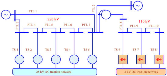
Figure 1.
Diagram of the modeled network traction transformers with a capacity of 40 MVA are installed on the AC TP. Step-down transformers with a capacity of 16 MVA and converter transformers with a capacity of 11.8 MVA are installed on the DC TP.
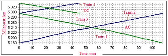
Figure 2.
Train schedule.
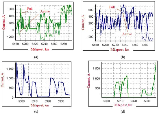
Figure 3.
Train schedule and current profiles of trains: (a)—down train No. 1; (b)—up train No. 2; (c)—down train No. 3; (d)—up train No. 4.
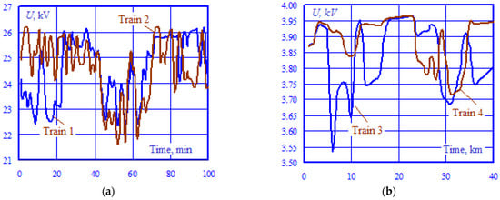
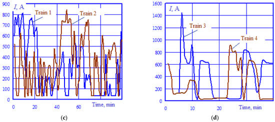
Figure 4.
Voltage on current collectors of electric locomotives (a,b) and current consumed by them (c,d).
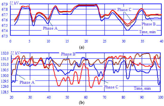
Figure 5.
Voltage in the buses of traction substations: (a)—TS 5; (b)—TS 8.

Figure 6.
The k2U factors for the high-voltage buses of AC traction substation.
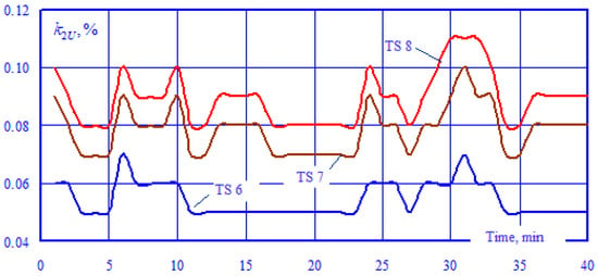
Figure 7.
The k2U factors for the high-voltage buses of AC traction substations.
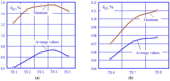
Figure 8.
Maximum and average values of k2U for high-voltage buses of AC (a) and DC (b) traction substations.


Figure 9.
Harmonic factors kU for high-voltage buses of TS 3 (a) and TS 8 (b).
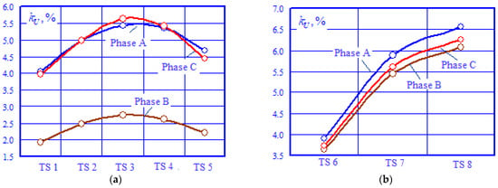
Figure 10.
Maximum values of harmonic factors kU for high-voltage buses of AC (a) and DC (b) traction substations.

Figure 11.
Spectra of voltage harmonics for buses of 220 kV TS 3 (a) and 110 kV TS 8 (b).

Figure 12.
Temperatures of the contact wire (CW) and support cable (SC) for down-train direction: the ambient temperature is assumed to be 20 °C.

Figure 13.
Currents of catenary wires for down-train direction.
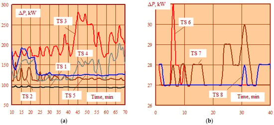
Figure 14.
Active power losses in transformers: (a)—AC TS transformers with a power of 40,000 kVA and voltage of 220/27.5 kV; (b)—DC TS converter transformers with a power of 16,000 kVA and voltage of 115/10 kV.
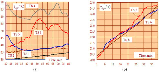
Figure 15.
Temperatures of the hottest points of transformers: (a)—transformer of TS 1; (b)—transformer of TS 6.
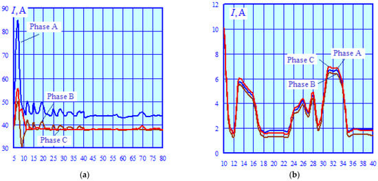
Figure 16.
Phase currents of high-voltage windings: (a)—transformer of TS 1; (b)—transformer of TS 6.
The dependences U = U(t), shown in Figure 4, indicate that the voltage at the pantographs is within acceptable limits: 21–29 kV for AC electric locomotives and 2.7–4 kV for DC electric rolling stock [33].
Figure 5 demonstrates the dependences U = U(t) of phase voltages in the 220 kV buses of TS 5 and 110 kV TS 8 leads. The substations were selected based on the condition of the maximum level of root mean square deviations (RMSD). The RMSD values of TS 5 are in the range of 12 to12.2 kV, and for TS 8, they lie within the range of 6.36–6.38 kV.
Figure 6 shows graphs of the unbalance factors k2U = k2U (t) in the high-voltage buses of AC TSs for two points of connection to the EPS networks. Similar dependences for DC TSs are shown in Figure 7. From the analysis of the presented results, we can conclude that the unbalance levels for all TSs do not exceed the normally acceptable values of 2%. The k2U values for DC TSs are tenths of a percent. With an increase in the traffic and under post-emergency conditions caused by the disconnection of the line between TS 5 and the EPS, the unbalance levels in the 220 kV buses of AC substations may exceed the permissible limits.
The values k2U were determined as follows:
- Based on the solution of a system of nonlinear steady-state equations written in phase coordinates, voltage modules and phases at the nodal points of the network are calculated.
- With the help of known transformations, the symmetric components of the forward, reverse, and zero sequences are calculated and the coefficients of asymmetry are determined.
The maximum and average values of k2U in the high-voltage buses of traction substations are shown in Figure 8. As seen in the figure, the elevated k2U values are observed in the 220 kV buses of TS 4.
Figure 9, Figure 10 and Figure 11 present the results of detecting non-sinusoidal conditions, while considering voltage harmonics up to the 40th inclusive. The sources of high harmonics are rectifier electric locomotives of alternating currents and rectifier–inverter units of traction substations of direct currents. The presence of harmonic distortion leads to the following negative effects:
- Power losses in the elements of the EES are increasing; for example, when high harmonic currents flow in the transformer, additional losses increase sharply and can reach 30 … 50% of the passport losses in copper;
- There is a reduction in the resource of power transformers as a result of additional heating of the insulation of the windings caused by losses of active power arising from the flow of currents of higher harmonics in them;
- The service life of asynchronous motors is reduced, which is associated with thermal aging of the insulation due to an increase in the temperature of the stator winding;
- When the voltage sinusoidal distortion occurs, an additional error in the measurement of electricity appears, which can lead to the output of the resulting error of the measuring complex beyond the permissible value;
- In the presence of a significant level of harmonics with numbers multiple of three, significant overheating of the neutral wire and contact burnout is possible; a break in the neutral wire, in turn, can lead to significant voltages at the terminals of individual electrical receivers and their failure;
- Resonant effects at frequencies of high harmonics can create serious problems for electrical equipment; the results of calculations and field measurements show the presence of resonances at frequencies of 21 … 23rd harmonics with a shift of resonances by 27 … 29th harmonics with short substation zones; in the case of three-way sections, resonances occur at 21 … 23rd harmonics even with relatively short zones.
The calculation results for non-sinusoidal conditions indicate that the levels of harmonic distortion exceed the maximum permissible values. To reduce high harmonics, both passive and active filters can be used.
Figure 12 presents the heating temperatures determined for the catenary wires in the inter-substation zone TS6-TS7. The dynamics of the changes in the currents flowing through these wires are shown in Figure 13. The maximum heating temperature of live parts does not exceed 24 °C.
Figure 14 shows the time dependences of active power losses ΔP in TS transformers. The losses do not exceed the nominal values. In the AC segment, the greatest losses are observed in transformer of TS 3. At DC TSs, an increased value of ΔP occurs at TS6. This is due to the network structure and the train schedule accepted for modeling.
4. Conclusions
Original methods and algorithms are presented that provide a complex modeling of complex asymmetric and non-sinusoidal modes of high-voltage electric networks feeding traction substations of mainline railways of alternating and direct currents. These methods and algorithms are implemented in the Fazonord industrial software package. They will allow you to correctly take into account the specific features of railway power supply systems, which are as follows:
- Significant spatial distribution and the length of the traction network may exceed several thousand kilometers;
- The heterogeneity of the subsystem structure, which consists of the fact that three-phase electric networks of various voltages form the power grid, and the traction power supply system is a single-phase network;
- Pulsating nature of active power in the traction network and at the high voltage inputs of traction substations;
- Movement of consumers in space;
- The sharply variable dynamics of changes in traction loads;
- Significant asymmetry and non-sinusoidal currents consumed by heavy substations;
- Electromagnetic influence of the traction network on adjacent transmission and communication lines, and on extended metal structures mounted along the railway route;
- A significant level of electromagnetic fields generated by an unbalanced traction network.
In addition to the power elements, the presented technology for determining the limits allows you to simulate the following active elements of a smart grid: controlled reactive power sources, harmonic conditioners, self-compensating power lines, etc. The models of controlled rectifiers and inverters that have no analogs have been developed for DC traction substations [27].
The developed modeling technology, software, and digital models can be effectively used to solve the following practical problems that arise during the design and operation of electric networks supplying traction substations:
- Determination of modes and indicators of power quality;
- Selection of methods and means to improve the power quality;
- Development of measures to improve the reliability of power supply and energy efficiency;
- Determination of the optimal load of traction transformers.
The modeling technique is universal and can be used to determine the operating parameters of electric power systems of any configuration and traction networks of various designs.
Author Contributions
Conceptualization, I.K.I., A.V.K., K.V.S., A.V.C., N.Q.H. and Y.S.V.; methodology, A.V.K. and K.V.S.; software A.V.K., N.Q.H. and A.V.C.; validation, A.V.K., I.K.I., I.H.B. and K.V.S.; formal analysis, A.V.K. and Y.S.V.; investigation, A.V.K., I.K.I., N.Q.H. and K.V.S.; resources, K.V.S.; data curation, N.Q.H.; writing—original draft preparation, A.V.C. and K.V.S.; writing—review and editing, A.V.K., N.Q.H., A.V.C., I.K.I. and K.V.S.; visualization, A.V.C. and Y.S.V.; supervision, A.V.K. and K.V.S.; project administration, A.V.C., I.H.B. and K.V.S.; funding acquisition, A.V.C. All authors have read and agreed to the published version of the manuscript.
Funding
This study is financed by the European Union-NextGenerationEU, through the National Recovery and Resilience Plan of the Republic of Bulgaria, project № BG-RRP-2.013-0001-C01.
Data Availability Statement
The original contributions presented in the study are included in the article, further inquiries can be directed to the corresponding author.
Acknowledgments
This work was carried out within the framework of the State Assignment “Applied scientific research” on the topic “Development of methods, algorithms, and software for modeling the operating parameters in traction power supply systems for DC railways”.
Conflicts of Interest
The authors declare no conflicts of interest.
References
- Bocharnikov, Y.V. Modeling of a traction power supply system for assessing electromagnetic compatibility with adjacent systems. Technol. Electromagn. Compat. 2008, 1, 45–55. [Google Scholar]
- Feng, D.; Zhou, H.; Lin, S. A Reactive Power Optimization Method for AC Metro Power Supply System Based on Particle Swarm Optimization Algorithm. In Proceedings of the 2023 IEEE Vehicle Power and Propulsion Conference (VPPC), Milan, Italy, 24–27 October 2023. [Google Scholar]
- Baranov, I.A.; Agunov, A.V. Modeling of reactive power compensation processes in a traction power supply system using Matlab-Simulink. Intell. Technol. Transp. 2021, 2, 5–12. (In Russian) [Google Scholar]
- Konstantinova, Y.A.; Lee, V.N.; Konstantinov, A.M. Simulation modeling of electricity transit from an external power supply system via an AC traction network. Bull. Amur State Univ. 2016, 4, 70–76. (In Russian) [Google Scholar]
- Yang, S.; Chen, Y.; Dong, Z.; Wu, J. A collaborative operation mode of energy storage system and train operation system in power supply network. Energy 2023, 276, 127617. [Google Scholar] [CrossRef]
- Garanin, M.A.; Boshkareva, T.V.; Frolenkov, S.A. Modeling of an alternating current traction power supply system for passing high-mass trains. Bull. Transp. Volga Reg. 2016, 5, 22–27. (In Russian) [Google Scholar]
- Sun, L.; Zhang, X.; Liu, M.; Peng, H. Modeling and influence research of traction power supply system based on ADPSS. In Proceedings of the 2014 International Conference on Power System Technology, Chengdu, China, 20–22 October 2014. [Google Scholar]
- Zhang, Y.W.; Chen, R.M.; Xiao, Y.; Zhao, W.; Li, X.R.; Zhang, G.D. Measurement-based modeling of traction power supply system. In Proceedings of the 2011 International Conference on Advanced Power System Automation and Protection, Beijing, China, 16–20 October 2011. [Google Scholar]
- Li, J.X.; Li, X.R.; Deng, W.; Xu, Z.H.; Liu, Q.Y.; Zhang, Y.-W. Study on power systems transient stability considering traction power supply system measurement-based load model. In Proceedings of the 2011 International Conference on Advanced Power System Automation and Protection, Beijing, China, 16–20 October 2011. [Google Scholar]
- Yu, X. General Mathematical Model of AC Traction Power Supply System Simulation Based on Mathematical Reasoning and Its Application Research. In Proceedings of the 2020 IEEE International Conference on Artificial Intelligence and Information Systems (ICAIIS), Dalian, China, 20–22 March 2020. [Google Scholar]
- Fan, Z.; Tian, X.; Sun, X.; Yang, X.; Zhang, H.; Tan, Z. Research on Modeling and Power Supply Capability of AT Traction Power Supply System. In Proceedings of the 2021 International Conference on Artificial Intelligence and Electromechanical Automation (AIEA), Guangzhou, China, 14–16 May 2021. [Google Scholar]
- Lu, C.; Li, X.; Chen, S. Composite Load Equivalent Modeling of Traction Power Supply System. In Proceedings of the 2021 3rd Asia Energy and Electrical Engineering Symposium (AEEES), Chengdu, China, 26–29 March 2021. [Google Scholar]
- Yang, H.; Du, X.; Chen, B.; Cao, Y.; Zheng, L.; Wang, H. The Influence of Electrified Railway Traction Power Supply System on the Power Quality of Regional Power Grid. In Proceedings of the 2023 IEEE International Conference on Sensors, Electronics and Computer Engineering (ICSECE), Jinzhou, China, 18–20 August 2023. [Google Scholar]
- Xia, S.; Wang, Y.; Wang, L.; Zhang, C.; Wang, C. Optimization Design of Traction Substation in APM Traction Power Supply System based on Adaptive Particle Swarm Algorithm. In Proceedings of the 2019 IEEE International Conference on Power, Intelligent Computing and Systems (ICPICS), Shenyang, China, 12–14 July 2019. [Google Scholar]
- Yan, N.; Wang, J.; Ping, A.; Liu, R.; Xiao, R.; Yan, H. Simulation Study on Dynamic Distribution of Ground Fault Current in Low and Medium Speed Magnetic Levitation Traction Power Supply System. In Proceedings of the 2022 IEEE International Conference on High Voltage Engineering and Applications (ICHVE), Chongqing, China, 25–29 September 2022. [Google Scholar]
- Sokol, Y.; Sychenko, V.; Voitovych, Y.; Kosariev, Y.; Styslo, B.; Hubskyi, P. AC/DC Converter for DC Traction Power Supply System with High-Speed Train Operation. In Proceedings of the 2019 IEEE 6th International Conference on Energy Smart Systems (ESS), Kyiv, Ukraine, 17–19 April 2019. [Google Scholar]
- Chen, M.; Wen, T.; Jiang, W.; Luo, J. Modelling and Simulation of New Traction Power Supply System in Electrified Railway. In Proceedings of the 2015 IEEE 18th International Conference on Intelligent Transportation Systems, Las Palmas, Spain, 15–18 September 2015. [Google Scholar]
- Xia, M.; Zhou, Y.; Huang, Y.; Yang, H.; Tai, Y. Research on Short-Circuit Characteristics of Subway DC Traction Power Supply System. In Proceedings of the 46th Annual Conference of the IEEE Industrial Electronics Society, Singapore, 18–21 October 2020. [Google Scholar]
- Xiang, N.; Yuan, Q.; Wang, C. Study on the adaptability of traction power supply system under the operation of high density heavy haul train. In Proceedings of the IEEE 6th International Electrical and Energy Conference (CIEEC), Hefei, China, 12–14 May 2023. [Google Scholar]
- Han, A.; Yu, L.; Wang, L.; Jia, X.; Sun, W.; Bi, Y. Research on the influence of urban metro traction power supply system on power grid harmonics. In Proceedings of the First International Conference on Electronics Instrumentation & Information Systems (EIIS), Harbin, China, 3–5 June 2017. [Google Scholar]
- Wang, J.; Han, Y.; Wang, X.; Zhan, X.; Li, L.; Chen, W. Research on Optimal Dispatch of Multi-energy Complementary Traction Power Supply System Based on PV Uncertainty. In Proceedings of the 10th International Conference on Power and Energy Systems Engineering (CPESE), Nagoya, Japan, 8–10 September 2023. [Google Scholar]
- Zhu, W.; Wang, X.; Chang, M.; Lyu, X. Harmonic State Space Modeling and Stability Analysis of Traction Power System Connected to the Three-Phase Grid. In Proceedings of the 17th Conference on Industrial Electronics and Applications (ICIEA), Chengdu, China, 16–19 December 2022. [Google Scholar]
- Rylov, A.; Ilyushin, P.; Kulikov, A.; Suslov, K. Testing photovoltaic power plants for participation in general primary frequency control under various topology and operating conditions. Energies 2021, 14, 5179. [Google Scholar] [CrossRef]
- Nezevak, V.; Cheremisin, V. Prediction of Bandwidth Increase of Railways Areas at the Change Expense of The Direct Current Traction Power Supply System Characteristics by Implementation of Electric Storage Units. In Proceedings of the 2020 International Ural Conference on Electrical Power Engineering (UralCon), Chelyabinsk, Russia, 22–24 September 2020. [Google Scholar]
- Huang, S.; Wu, M. Reliability Evaluation System for Traction Power Supply System of Electric Railways. In Proceedings of the 2018 IEEE 9th International Conference on Software Engineering and Service Science (ICSESS), Beijing, China, 23–25 November 2018. [Google Scholar]
- Xu, C.; Han, Y.; Li, Q.; Chen, W.; Fu, W. Research on Coordinated Control Method of PV and Battery Access Traction Power Supply System Based on RPC. In Proceedings of the 2020 IEEE Sustainable Power and Energy Conference (iSPEC), Chengdu, China, 23–25 November 2020. [Google Scholar]
- Zakaryukin, V.P.; Kryukov, A.V. Complex Asymmetric Modes of Electrical Systems; Irkutsk University: Irkutsk, Russia, 2005; 273p. (In Russian) [Google Scholar]
- Tian, Z.; Zhao, N.; Hillmansen, S.; Su, S.; Wen, C. Traction Power Substation Load Analysis with Various Train Operating Styles and Substation Fault Modes. Energies 2020, 13, 2788. [Google Scholar] [CrossRef]
- Meng, X.; Zhang, Q.; Hu, G.; Liu, F.; Zhang, G. Multiple vehicles and traction network interaction system stability analysis and oscillation responsibility identification. IEEE Trans. Power Electron. 2024, 39, 6148–6162. [Google Scholar] [CrossRef]
- Zakaryukin, V.P.; Kryukov, A.V. Modeling of DC Traction Power Supply Systems Based on Phase Coordinates; Direct-Media: Moscow, Russia, 2023; 156p. [Google Scholar]
- Smirnov, A.S.; Solonina, N.N.; Suslov, K.V. Separate measurement of fundamental and high harmonic energy at consumer inlet—A way to enhancement of electricity use efficiency. In Proceedings of the 2010 International Conference on Power System Technology: Technological Innovations Making Power Grid Smarter, POWERCON2010, Hangzhou, China, 24–28 October 2010. [Google Scholar]
- Suslov, K.; Kryukov, A.; Ilyushin, P.; Kryukov, A.; Shepovalova, O. Modeling of modes of traction power supply systems equipped with renewable energy sources. Energy Rep. 2023, 9, 447–461. [Google Scholar] [CrossRef]
- Rules of Technical Operation of Railways of the Russian Federation; Ministry of Transport of the Russian Federation: Moscow, Russia, 2022.
Disclaimer/Publisher’s Note: The statements, opinions and data contained in all publications are solely those of the individual author(s) and contributor(s) and not of MDPI and/or the editor(s). MDPI and/or the editor(s) disclaim responsibility for any injury to people or property resulting from any ideas, methods, instructions or products referred to in the content. |
© 2024 by the authors. Licensee MDPI, Basel, Switzerland. This article is an open access article distributed under the terms and conditions of the Creative Commons Attribution (CC BY) license (https://creativecommons.org/licenses/by/4.0/).