1. Introduction
The advent of electric vehicles (EVs) in public transportation marks a significant shift in the transportation sector. The International Energy Agency reports that over 26 million EVs were on the road in 2022, reflecting a sales increase of approximately 60% compared to 2021 [
1]. As sales escalate, there is a growing market concern regarding the thermal management systems (TMSs) of EVs [
2]. Essential components of a TMS in battery EVs include the air conditioning system for the cabin, the battery TMS (BTMS), and the driving motor TMS [
3]. BTMSs are typically categorized into air-cooled and liquid-cooled types. Many commercial EV manufacturers opt for air-cooled BTMSs due to their simple structure, low initial costs, lightweight characteristics, and ease of maintenance [
4]. Liquid-cooled systems, despite their higher complexity, initial cost, and weight, offer compact structures and superior cooling capabilities [
5]. The liquid-cooled type operates by circulating a coolant around the batteries to absorb heat generated during their charge and discharge cycles, subsequently transferring this heat through a heat exchanger to the vapor compression cycle. Higher charge or discharge rates correspond to increased heat generation [
6], necessitating advancements in BTMSs as EV performance improves. Although higher coolant flow rates enhance heat transfer, they also induce greater pressure drops [
7,
8].
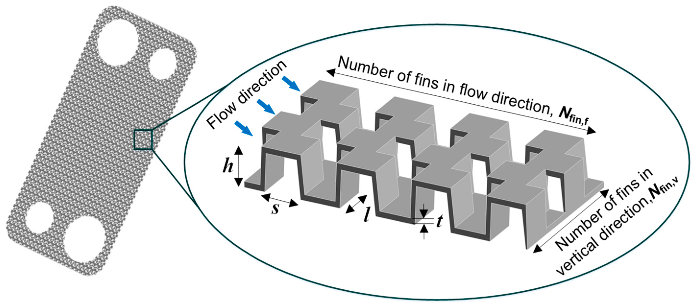
Plate heat exchangers, such as chevron, wavy, dimple, and offset-fin types, are utilized in EV BTMSs. Offset-fin and dimple types, in particular, are prevalent due to their efficiency [
8]. Offset fins, known for significantly enhancing heat transfer by periodically interrupting boundary layers and creating oscillating velocity in the fin wakes [
9], simultaneously cause considerable pressure drops. This necessitates a balanced analysis of thermo-hydraulic performance in heat exchangers. To explain, the larger pressure drop results in reduced coolant flow rate if the same circulation pump is used. Since the lower coolant flow rate causes a reduction in the heat transfer rate, comparing various heat exchangers at the same coolant flow rate is not reasonable. Dimple configurations are recognized for achieving high heat transfer enhancement with relatively low pressure losses [
10]. The remainder of this section summarizes previous research on the thermal and hydraulic performance of heat exchangers.
Fernandez-Sera et al. [
11] conducted an experimental analysis on single-phase heat transfer between water and ethylene glycol solutions (10 to 30 wt.%) using an offset-fin heat exchanger. They developed an empirical correlation, utilizing the Wilson plot method, to determine the convection heat transfer coefficient as a function of the Reynolds number. This method is prevalent in various studies [
12]. Yang et al. [
13] introduced a dimensionless parameter representing the ratio of the effective fin surface area to the square of fin thickness for offset fins, suggesting that this parameter influences the advantages and disadvantages of reducing fin length. Park et al. [
14] established correlations for the Colburn j and friction factors from experiments with offset-fin heat exchangers, also detailing an optimization technique involving six independent variables to enhance the thermo-hydraulic performance of offset-strip heat exchangers. Mada et al. [
15] proposed a correlation for heat transfer between the gaseous phases of R-134a and R-1234yf based on computational fluid dynamics (CFD) simulations. They highlighted the effectiveness of CFD analysis in deriving correlations by comparing their j factor with existing literature data. Ismail et al. [
16], Piper et al. [
17], and Mocnuk et al. [
18] also confirmed the utility of CFD in heat transfer analysis. Research extends beyond single-phase heat transfer, encompassing various correlations for evaporation heat transfer found in the literature. Jige et al. [
19] studied the evaporation heat transfer of R-1234ze(E) and R-32 in a plate-fin heat exchanger, noting that mass flux directly impacts the heat transfer coefficient more than heat flux. Similar findings were reported by Prabakaran et al. [
20,
21], although some studies [
22,
23] indicate that heat flux and saturation temperature significantly influence evaporation heat transfer. Kim et al. [
24] examined the thermo-flow characteristics of offset-fin heat exchangers by a numerical method in laminar regimes. They provided multiple correlations that are applicable in each specific range of beta, which is a parameter calculated from total and vacant area. At present, there are many studies on optimization of heat exchangers according to several design parameters based on the genetic algorithm. Guan et al. [
25] derived correlations of the j and f factors by numerical analysis, then carried out optimization of PFHE. Cao et al. [
26] also provided j and f factor correlations. Here, the correlations for both laminar and turbulent flow are distinguished, and a standard for the evaluation of the Reynolds number is provided. The genetic algorithm is also used to optimize fin design. Jamil et al. [
27] conducted not only thermal and hydraulic analysis but also economic and exergy analysis according to three fin geometries using numerical codes, and Moon et al. [
28] utilized the genetic algorithm for PFHE thermal and economic optimization.
The discharge process in EV batteries generates multiple forms of heat, including ohmic, reaction, polarization, and secondary reaction heat, all of which contribute to temperature rise [
29]. The heat generated by batteries varies and is influenced by factors such as charging or discharging current, battery temperature, and voltage [
30]. Thus, EVs frequently require enhanced cooling capacity to maintain battery efficiency. The recommended operating temperature range for lithium-ion battery packs is between 20 and 50 °C [
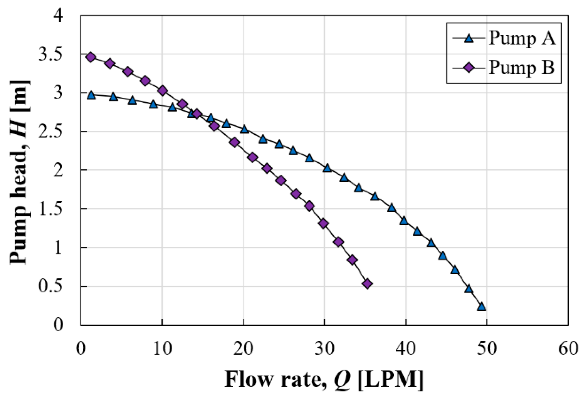
3]. Generally, increasing the coolant’s mass flow by increasing the pump’s RPM can improve the heat transfer rate. The mass flow rate is determined by the pump’s performance curve and the heat exchanger’s resistance curve, which indicates pressure loss.
As highlighted previously, optimizing heat exchangers requires careful consideration of both heat transfer and pressure loss, particularly for offset fins, due to their significant impact on pressure drop. Increased pressure loss across a heat exchanger reduces the mass flow rate [
31], which, in turn, affects the heat transfer rate [
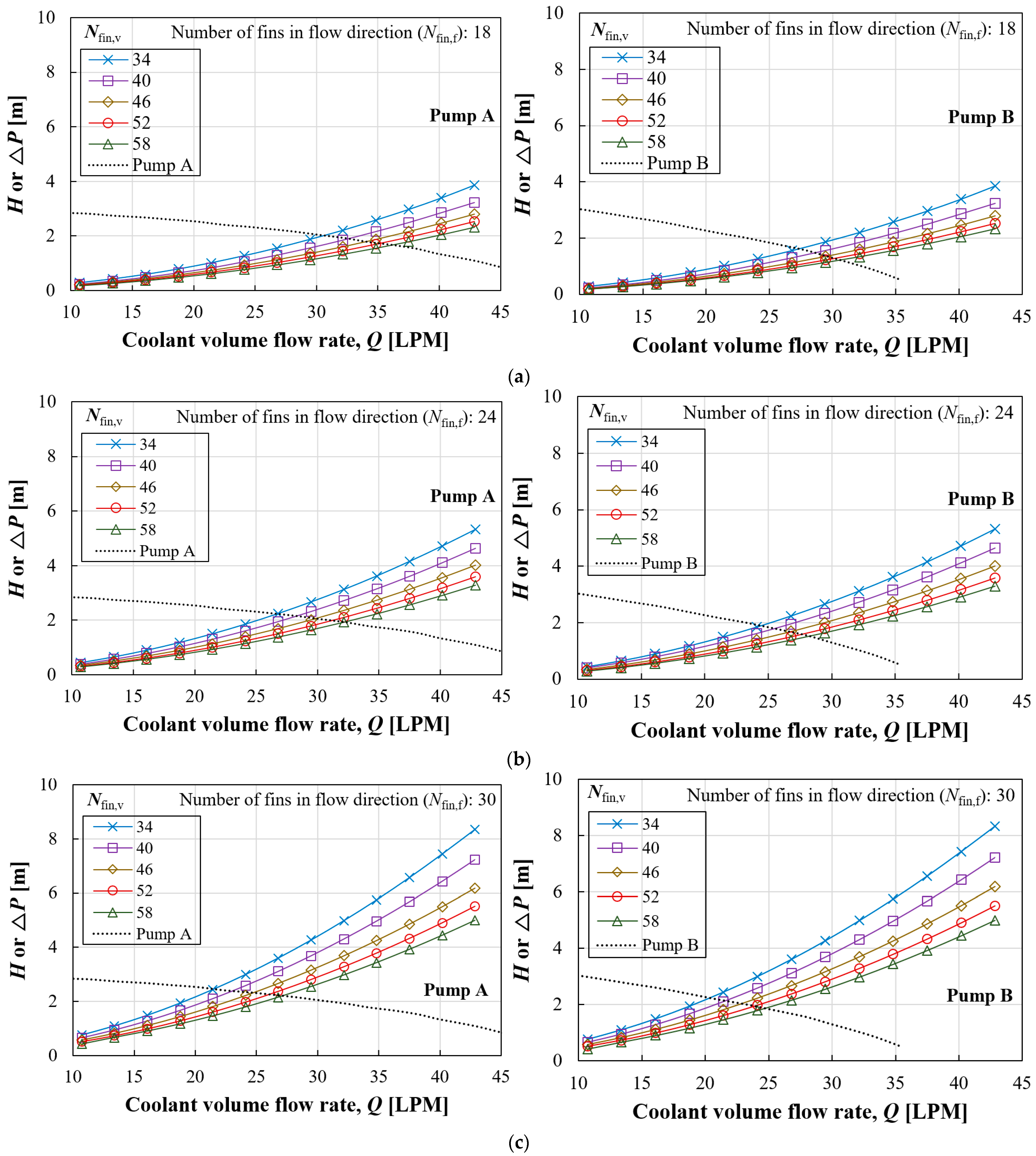
11]. It is crucial to assess the thermal performance of various heat exchanger designs based on actual mass flow rates derived from the performance and resistance curves. Although studies on optimization of offset fin structure and development of correlations are very common, it is hard to find analysis combining the thermo-hydraulic performance of heat exchangers with pump performance curves.
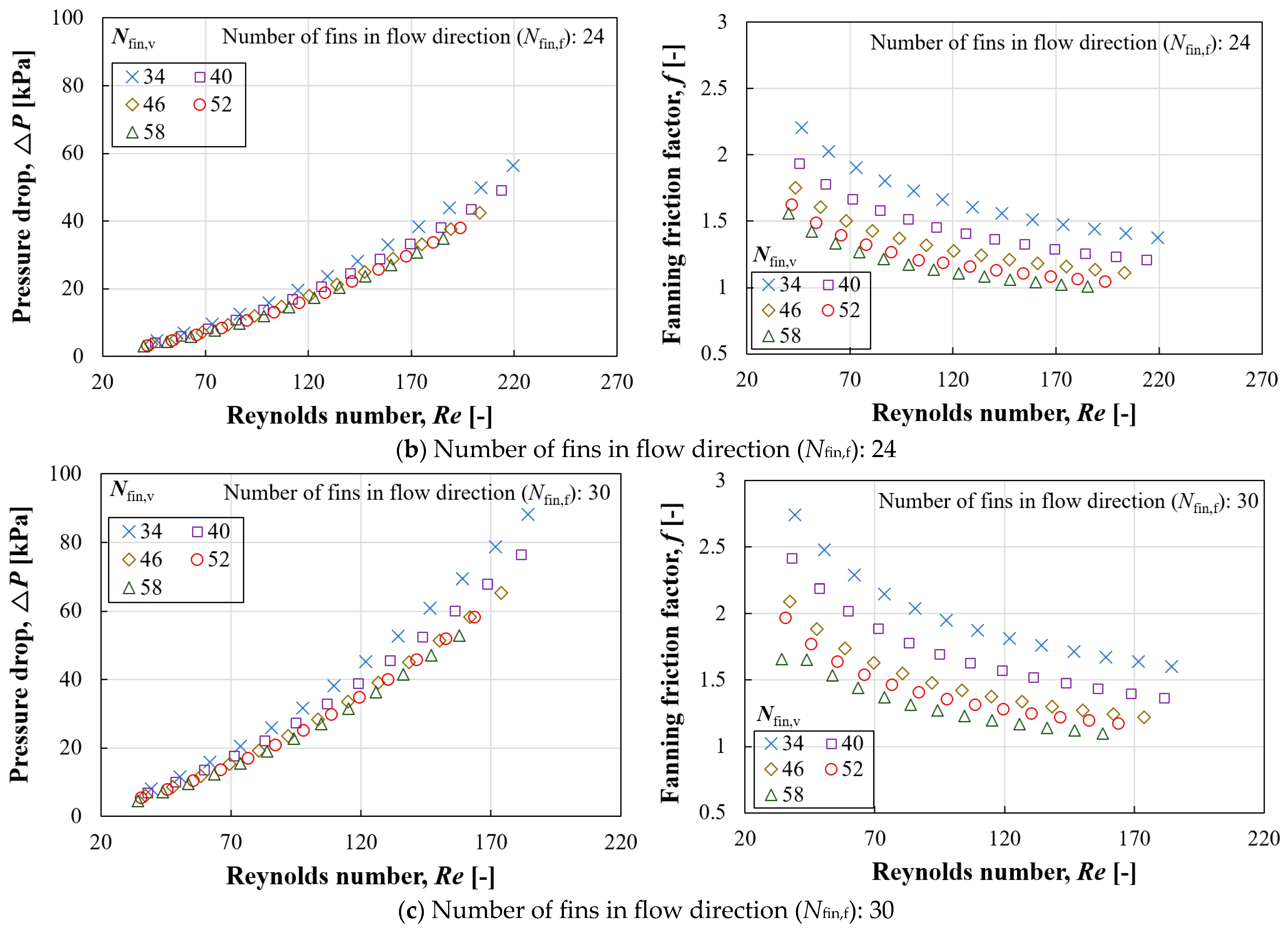
Consequently, this research aims to (1) provide comprehensive design data on the geometric effects of offset fins. This analysis provides dimensionless numbers such as j and f factors for various fin design cases to understand the thermo-hydraulic characteristics. The next aim is to (2) establish correlations for single-phase heat transfer based on CFD analysis. The correlation for the f factor enables generation of resistance curves by inputting Re and the number of fins. Since the point where the resistance curve intersects with the performance curve means the actual coolant flow rate, the heat transfer rate in this condition can be calculated based on the correlation for the j factor. The last aim is to (3) offer a practical comparison of heat exchanger models reflecting the performance curve of the pump and the resistance curve of the heat exchanger. Since the convective heat transfer coefficient of each case at the actual coolant flow rate is obtained from correlations, the expected heat transfer rate in this condition is calculated using the effectiveness–NTU method.
4. Conclusions
This research aimed to provide a comprehensive analysis focusing on (1) the impact of offset fin geometry on design, (2) correlations for single-phase heat transfer derived from CFD, and (3) a practical comparison of heat exchanger models that incorporates both the pump’s performance curve and the heat exchanger’s resistance curve. The key findings are as follows:
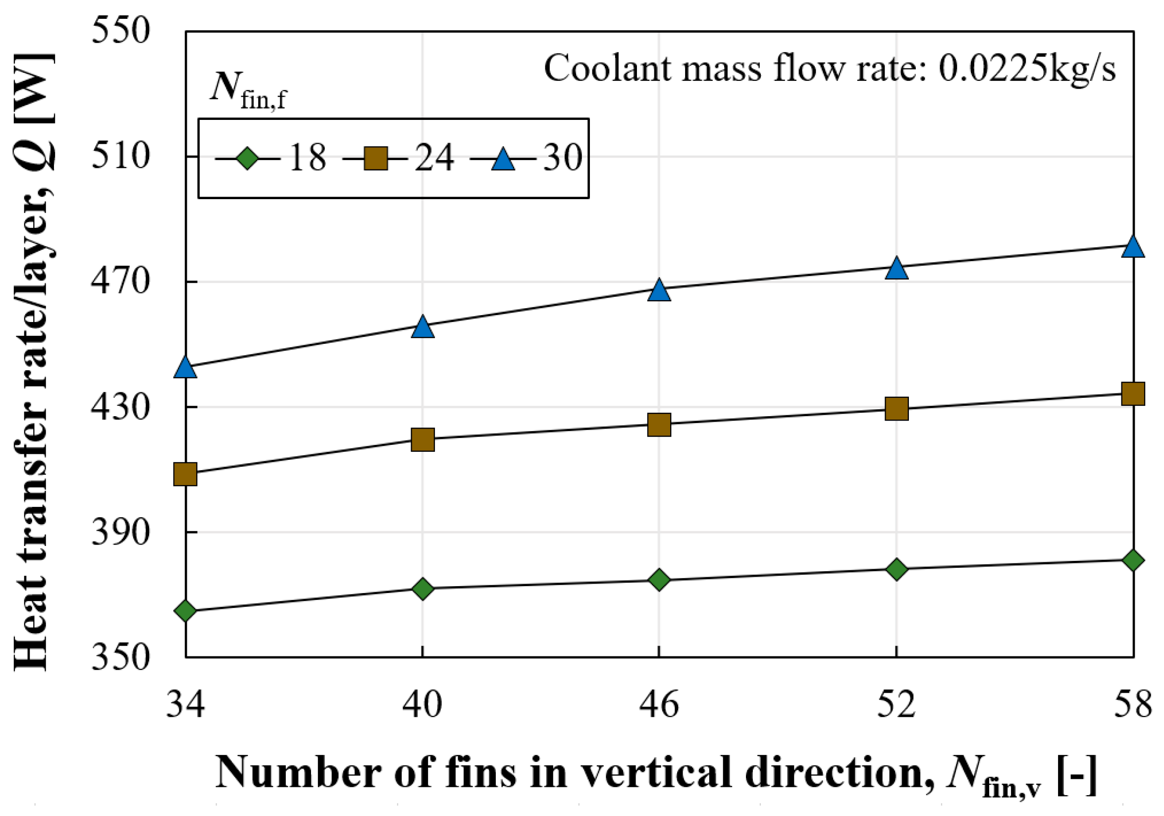
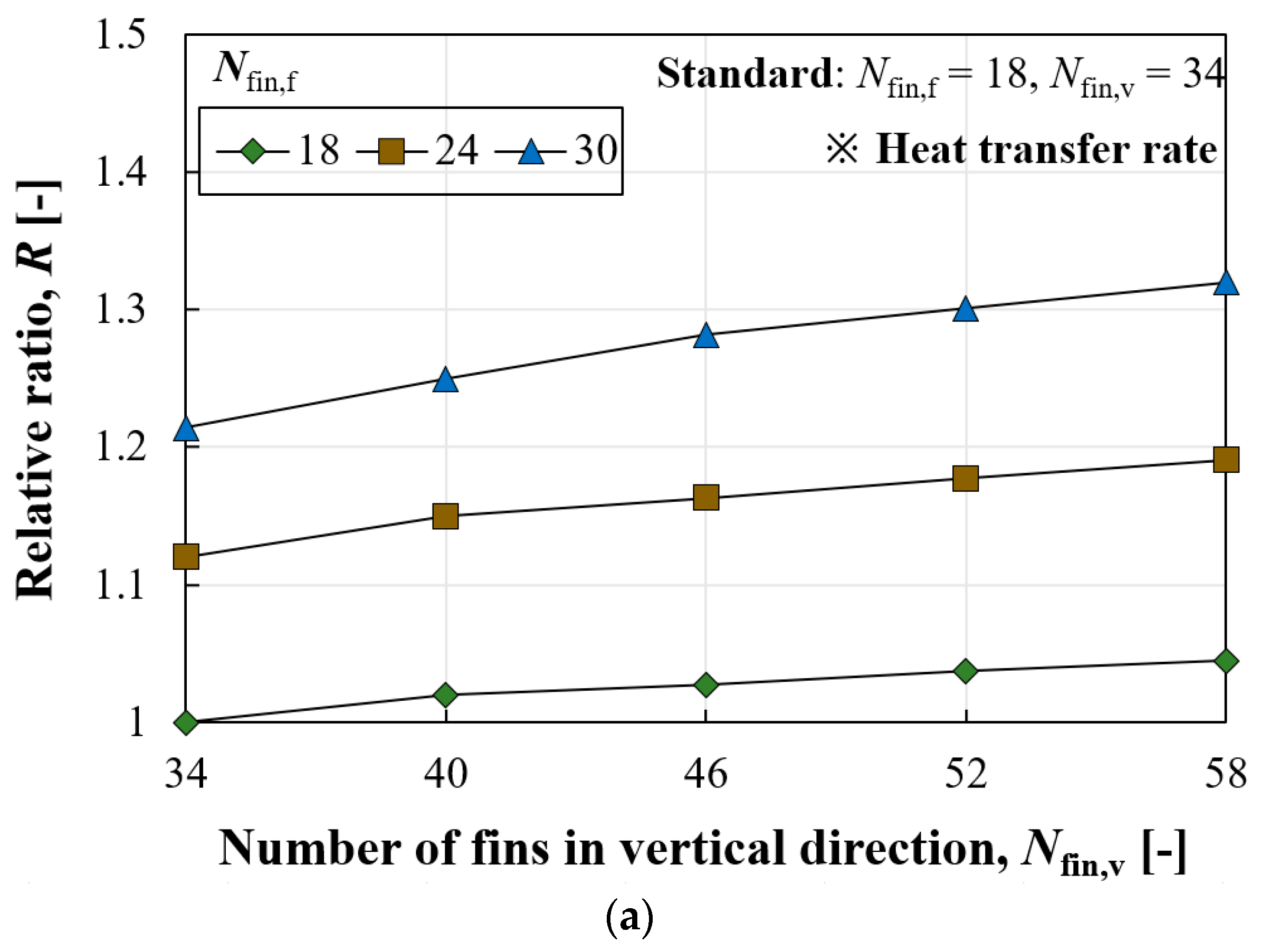
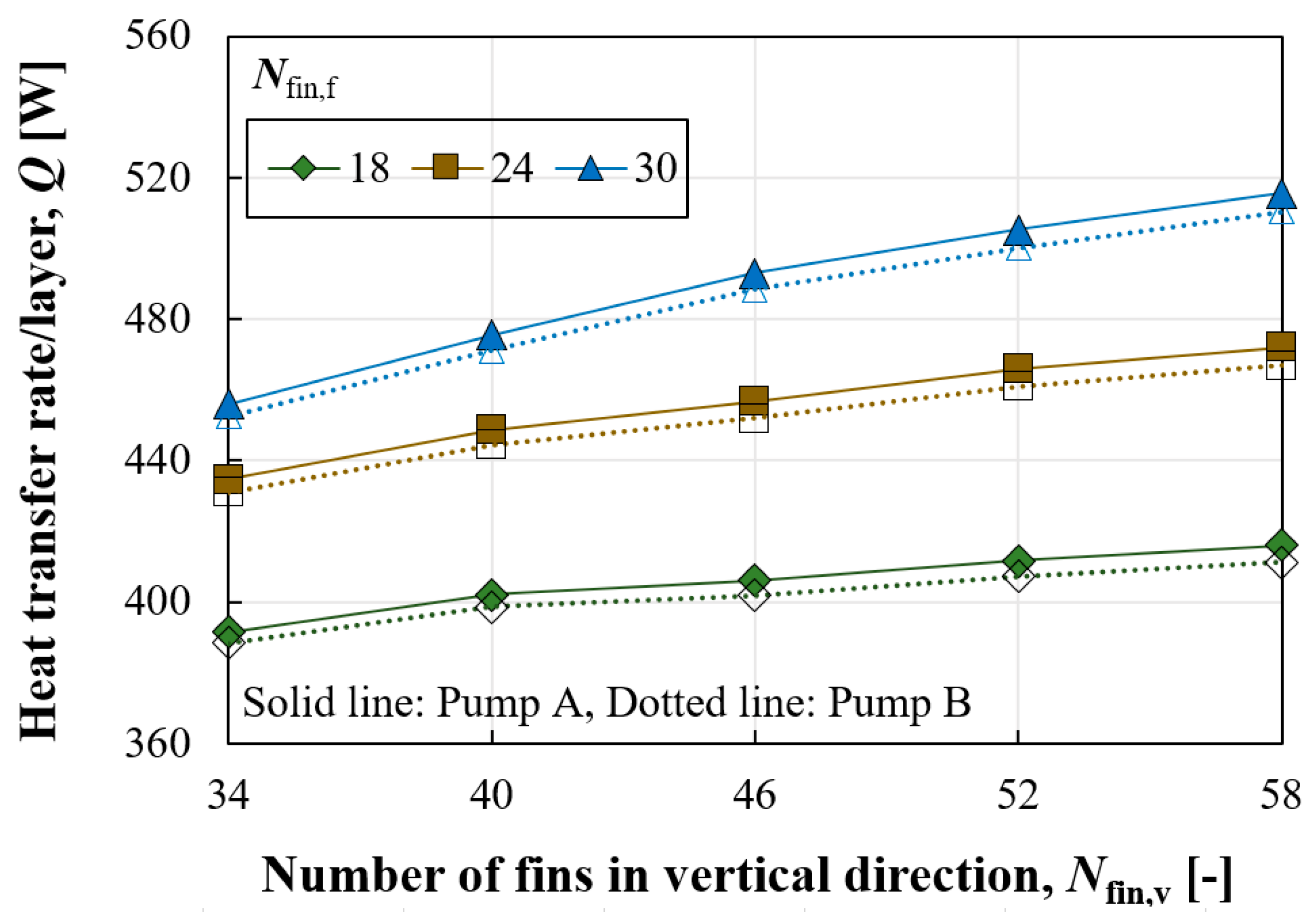
The heat transfer rate tends to increase with more fins in both directions. However, the increase in the heat transfer rate according to Nfin,v was significantly different depending on Nfin,f. The difference in heat transfer rate between Nfin,v values of 34 and 58 was about 4.48% when Nfin,f was 18, while it was 8.74% for Nfin,f of 30. The increase in the heat transfer rate can be attributed to two factors: an increase in surface area and an enhanced convective heat transfer coefficient. In the case of Nfin,f of 18, the increase in surface area between Nfin,v values of 34 and 58 was 4.94%, which is only a 0.45% difference compared to the increase in heat transfer rate, indicating that the heat transfer rate was primarily enhanced due to the enlarged surface area. On the other hand, in the case of Nfin,f of 30, the increase in surface area between Nfin,v values of 34 and 58 was 5.34%, suggesting that the remaining increase was due to the enhanced convective heat transfer coefficient.
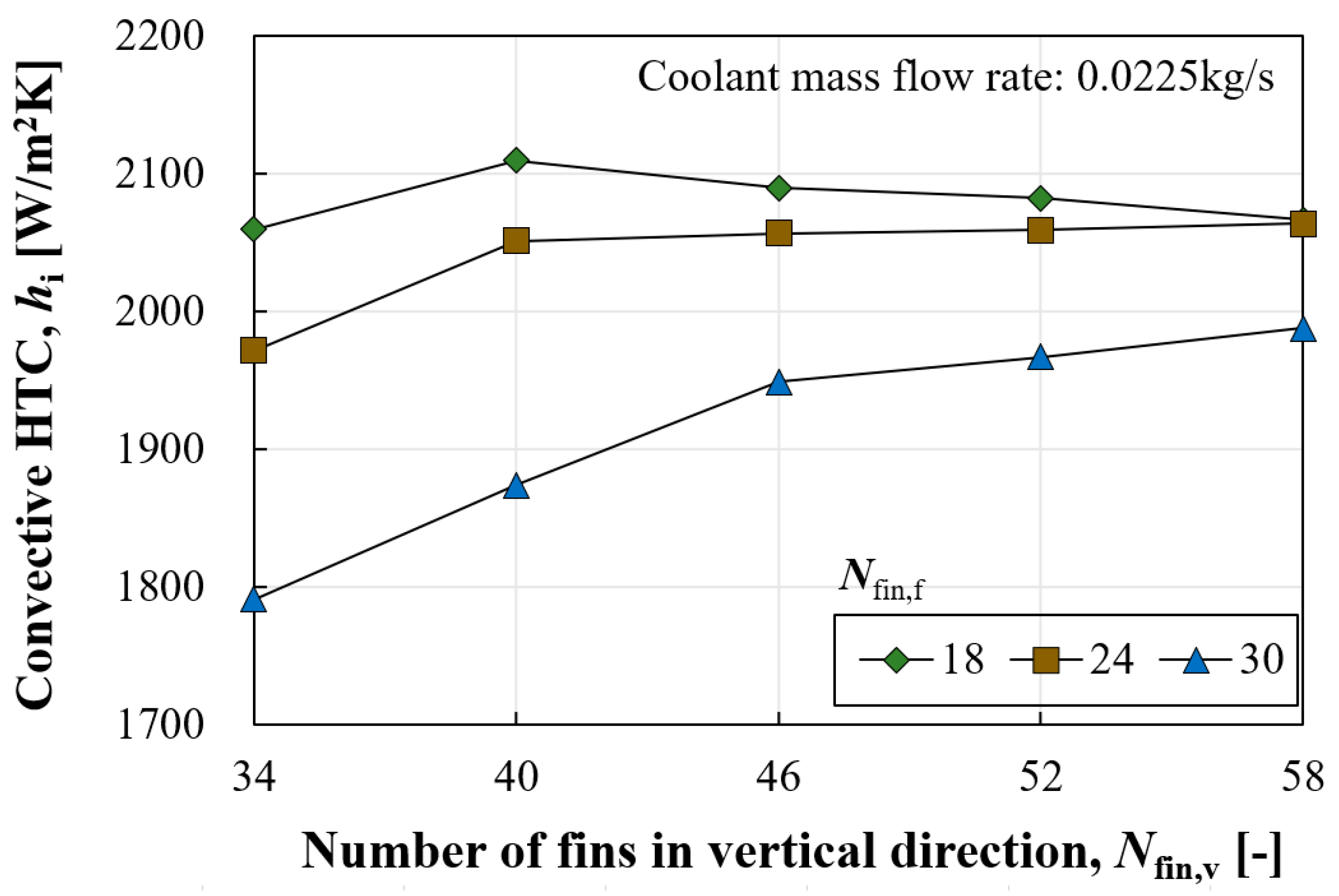
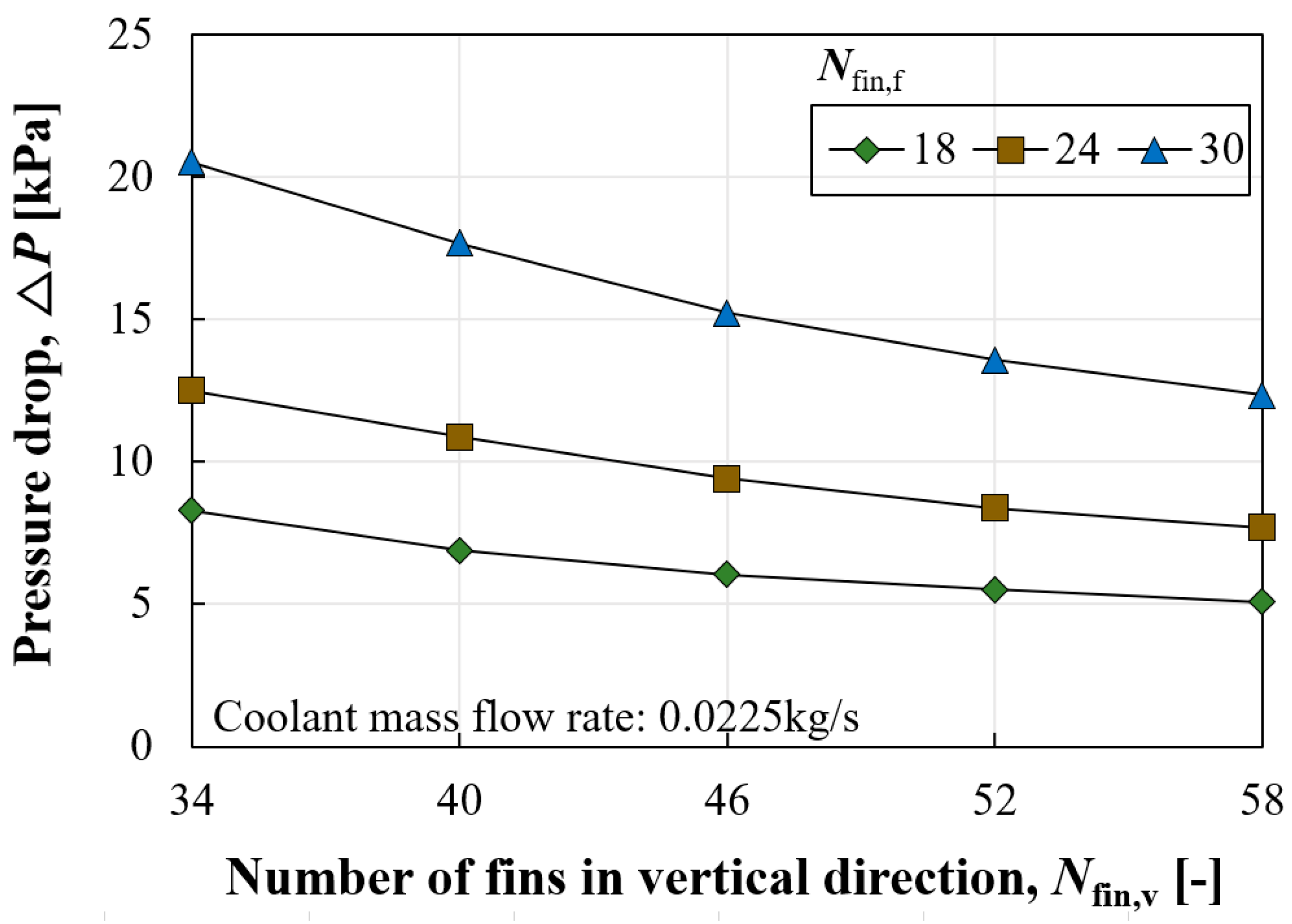
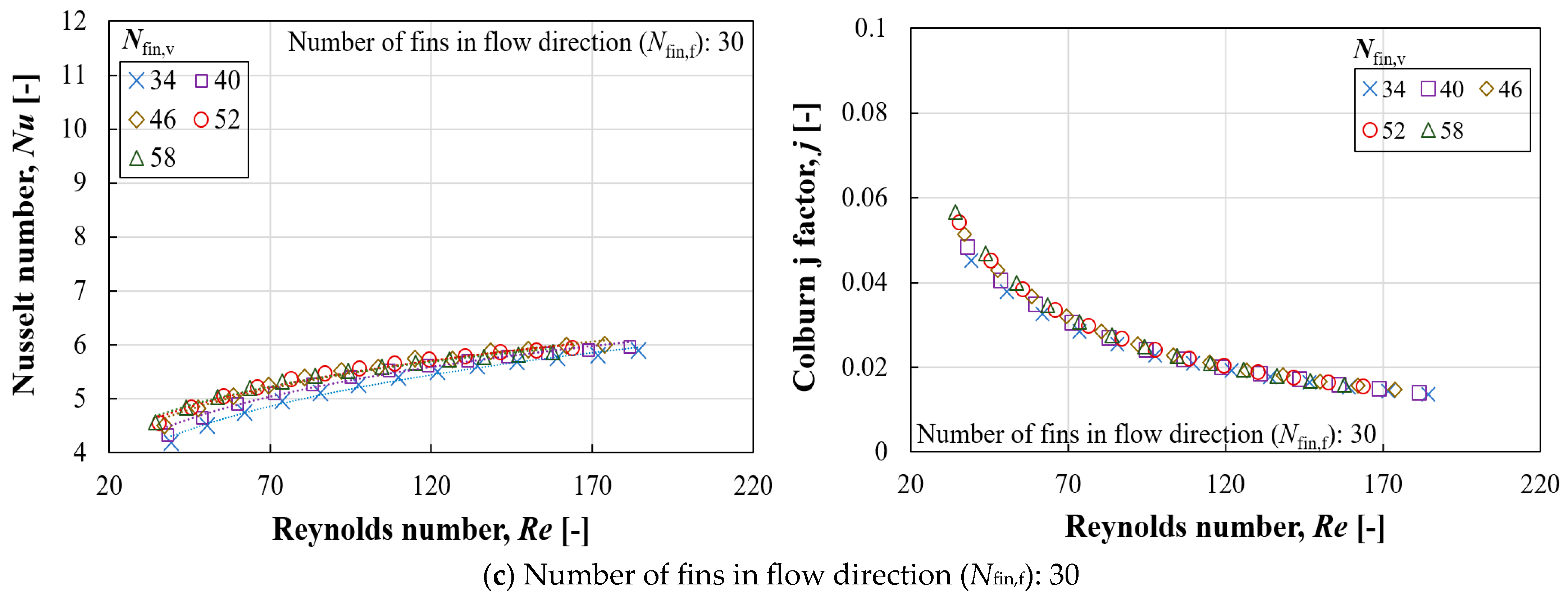
The convective heat transfer coefficient and pressure drop according to Nfin,v presented inverse symmetry characteristics. That is, more fins in the vertical direction were beneficial not only in reducing pressure loss but also in enhancing the heat transfer coefficient. Similarly, the increase or decrease in these parameters varied according to Nfin,f. Increasing Nfin,v was advantageous in both thermal and hydraulic aspects, whereas increasing Nfin,f had a negative impact by causing greater pressure loss and a reduced convective heat transfer coefficient. However, the increase in surface area compensated for the reduced convective heat transfer coefficient.
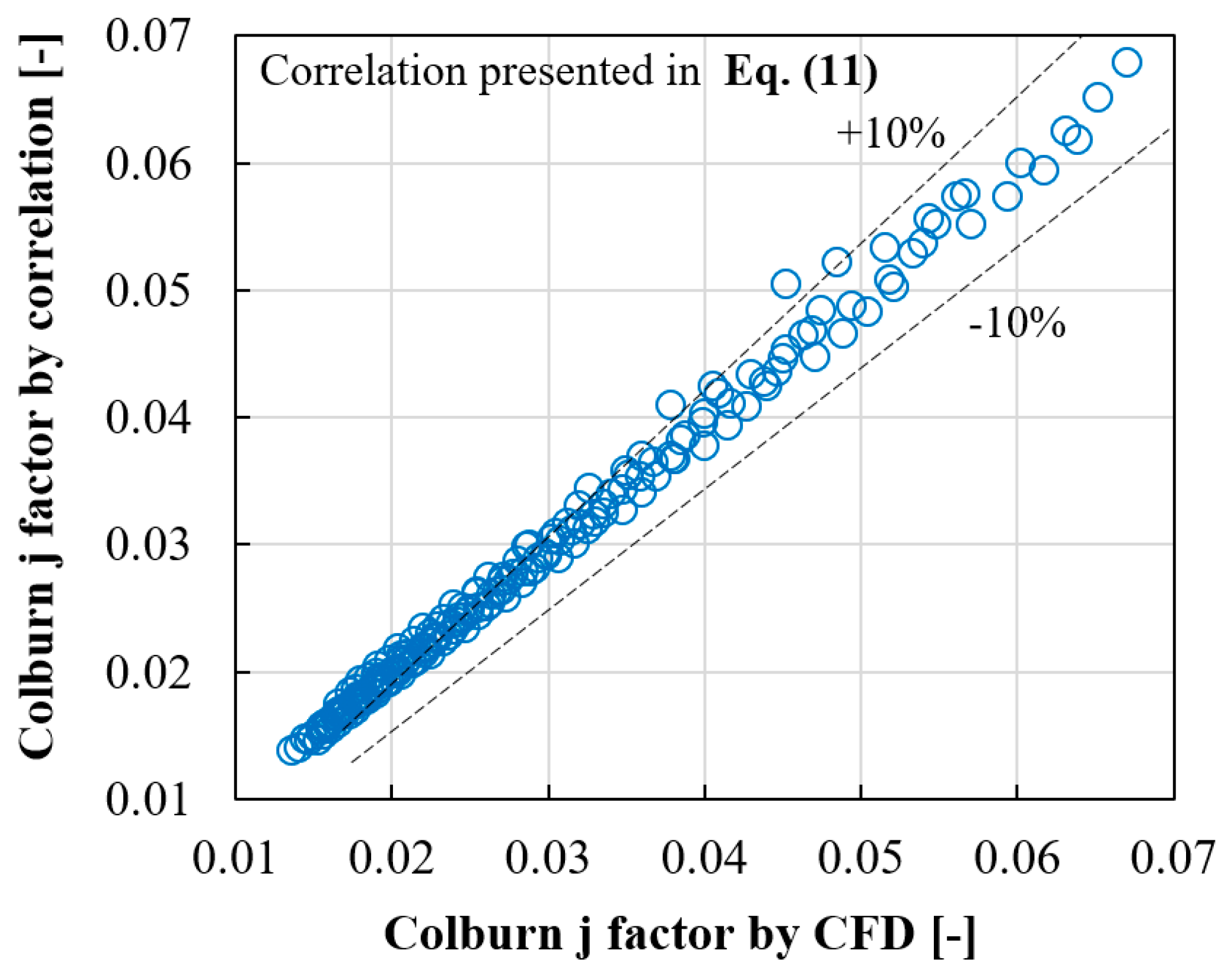
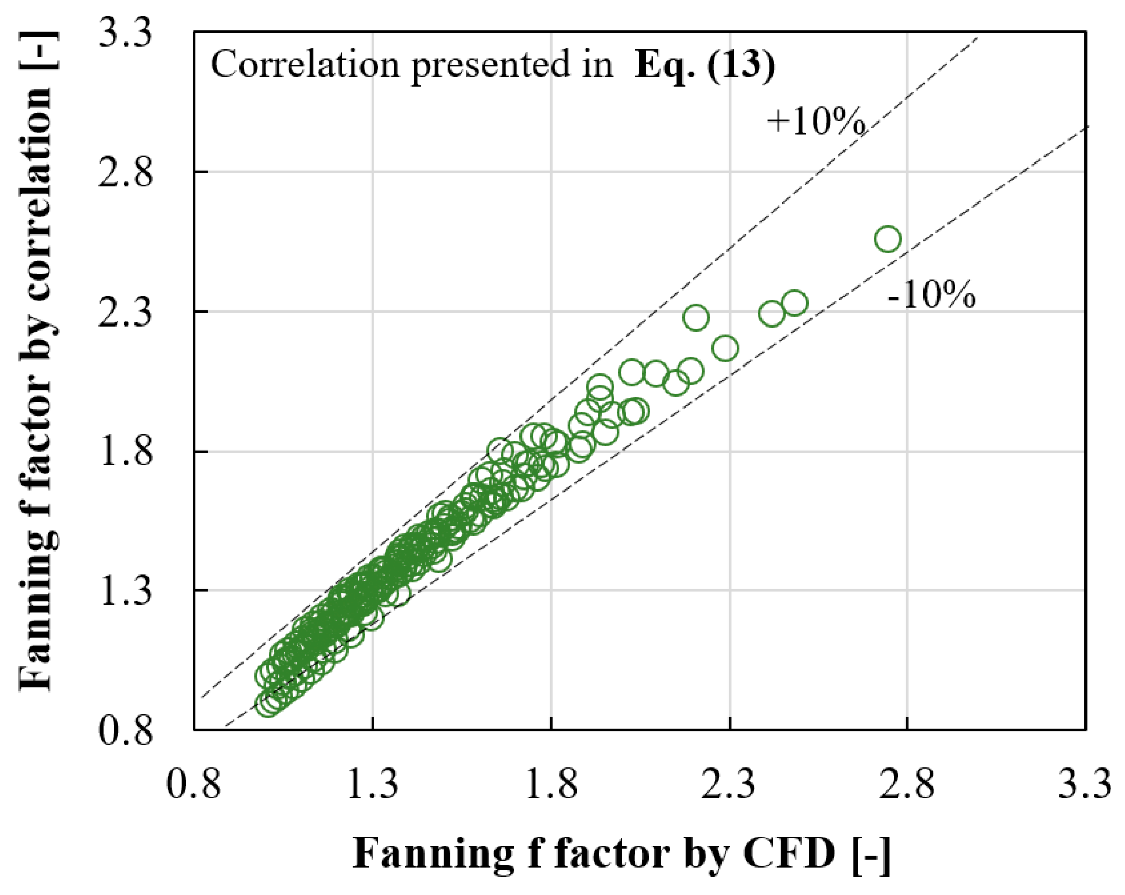
Further CFD analysis, incorporating various coolant flow rates, facilitated the establishment of relationships between different parameters (such as the Nusselt number, Colburn j factor, and Fanning f factor) in relation to the Reynolds number. The correlations defining the j and f factors with respect to the Reynolds number and the number of fins in each direction have been successfully derived, demonstrating errors of less than ±10%.
The study assumed two hypothetical pumps with differing performance curves to calculate the actual coolant flow rate for each pump. The actual flow rate circulating through each geometric case was determined by identifying the intersection of the performance curve and the resistance curve of each case. Differences in pressure drop resulted in different coolant flow rates despite using the same circulation pump, showing a difference of 1.67 times between the minimum and maximum values. Although different coolant flow rates circulated in each case, there was no reversal in the heat transfer rate compared to the situation with a constant amount flowing. The impact of the pump’s performance curve on the heat transfer rate becomes relatively pronounced with increased pressure drop. When Nfin,f was 30, the ratio of maximum to minimum heat transfer rates was 8.73% with a constant coolant flow rate, but this ratio increased to 13.08% when considering the actual coolant flow rate facilitated by a pump.
Lastly, the correlations and methodology of this research can be utilized in future research analyzing the energy consumption of EV TMSs according to battery heat generation. In a TMS, the cooling capacity can be controlled by adjusting the coolant flow rate and/or changing the evaporation temperature of the refrigerant. The comparison of energy consumption according to control strategies in response to varying battery loads will be possible based on this research.
