Review

A Review of Flow Field and Heat Transfer Characteristics of Jet Impingement from Special-Shaped Holes

School of Mechanical Engineering, Xi’an Jiaotong University, Xi’an 710049, China
*
Author to whom correspondence should be addressed.
Energies 2024, 17(17), 4510; https://doi.org/10.3390/en17174510
Submission received: 26 July 2024 / Revised: 20 August 2024 / Accepted: 5 September 2024 / Published: 9 September 2024
(This article belongs to the Collection Advances in Heat Transfer Enhancement)

Abstract

:
The jet impingement cooling technique is regarded as one of the most effective enhanced heat transfer techniques with a single-phase medium. However, in order to facilitate manufacturing, impingement with a large number of smooth circular hole jets is used in engineering. With the increasing maturity of additive technology, some new special-shaped holes (SSHs) may be used to further improve the cooling efficiency of jet impingement. Secondly, the heat transfer coefficient of the whole jet varies greatly on the impact target surface. The experiments with a large number of single smooth circular hole jets show that the heat transfer coefficient of the impact target surface will form a bell distribution—that is, the Nusselt number has a maximum value near the stagnation region, and then rapidly decreases exponentially in the radial direction away from the stagnation region. The overall surface temperature distribution is very uneven, and the target surface will form an array of cold spots, resulting in a high level of thermal stress, which will greatly weaken the structural strength and life of the equipment. Establishing how to ensure the uniformity of jet impingement cooling has become a new problem to be solved. In order to achieve uniform cooling, special-shaped holes that generate a swirling flow may be a solution. This paper presents a summary of the effects of holes with different geometrical features on the flow field and heat transfer characteristics of jet impingement cooling. In addition, the effect of jet impingement cooling with SSHs in different array methods is compared. The current challenges of jet impingement cooling technology with SSHs are discussed, as well as the prospects for possible future advances.

1. Introduction

The gas turbine is an essential heat power conversion device, and as energy demand continues to grow, improving the efficiency of gas turbines has become a significant research focus. Enhancing the inlet temperature of the turbine represents a crucial avenue for boosting efficiency. Two main avenues exist to increase the maximum temperature that a gas turbine can withstand: the utilisation of high-temperature-resistant materials or the enhancement of the cooling technology employed in turbine blades. Of these, the improvement of cooling technology is of particular consequence. In the 1970s, the advent of jet impingement cooling for turbines saw a notable enhancement in the cooling effect.
Impingement cooling is a method of cooling in which a cooling medium is sprayed in the form of a jet onto the surface of the cooled component in order to remove heat. The thinness of the fluid on the target cooling surface of the surface layer results in a high convection heat transfer coefficient, making this a highly stable and effective cooling method. Jet impingement cooling has the advantage of a simple structure, low cost, ease of control, and a localised heat transfer effect. These factors have led to its widespread use in a number of industrial contexts, including food processing, steel annealing, glass tempering, textiles, paper, thin wood drying, electronic part cooling, and aircraft de-icing systems. It is also employed in the cooling of aviation engine blades and other applications.
The parameters to be measured in the study of jet impingement cooling include the temperature of the jet at the entrance and exit of the computational domain, the velocity of the hot and cold jets, the pressure distribution, and the pressure difference, among others. The efficacy of jet impingement cooling is assessed through the processing of experimental data. The question of how to further improve the performance of jet impingement heat transfer is a significant area of interest for the majority of researchers in this field. A significant number of scholars have conducted research into the factors affecting the heat transfer performance of jets. One of the main areas of investigation is the influence of nozzle geometry. Jambunathan et al. concluded that nozzle geometry affects turbulence intensity in the wall jet zone, which in turn affects heat exchange with the air. Garimella et al. [1] found that changing the diameter of the nozzle affects the heat transfer coefficient. In a comparative study, Brignoni et al. [2] observed notable discrepancies in heat transfer performance between a tapered nozzle and a round nozzle. It should be noted that variations in nozzle geometry extend beyond alterations in diameter; numerous studies have documented the use of specialised orifice shapes, including those with tapering or other intricate designs [3,4,5].
The single-jet impingement range is constrained, thereby yielding a mere partial cooling effect on the target surface. Moreover, the presence of a single jet results in the generation of a notable temperature gradient on the surface undergoing heat transfer. In practice, the array of jet impingement cooling is a more prevalent approach. The primary distinction between a single-hole jet and an array jet is the manner in which the gas flow interacts with the target plate. In a single-hole jet, the back row of the jet impacts the target plate directly, whereas in an array jet, the front row of the jet flows into the exit of the formation of the cross-flow, resulting in an offset back row of the jet that cannot directly impact the target plate. This offset impingement cooling effect reduces the effectiveness of the cooling process. Nevertheless, the implementation of a jet array can enhance the uniformity of the target surface temperature distribution, mitigate thermal stress, and align more closely with the requirements of turbine blades, electronic equipment, and other structures.
In recent years, numerous review papers have also examined the research on jet impingement cooling and outlined the techniques to optimise the heat transfer characteristics of jets. Barewar et al. [6], for instance, primarily discussed the impact of coolant properties, surface modification, and different geometrical parameters on the heat transfer of jets. Sarkar et al. [7] conducted a review of the techniques related to the enhancement of jet cooling by surface modification applied in electronic devices. Hussain et al. [8] provided a summary of the studies on the effect of target surface structure, extended jet orifices, and the use of nanofluids for coolant on impingement cooling. Ekkad et al. [9] conducted a review and provided an outlook on the various factors affecting jet cooling, including jet arrays and nozzle geometries. While these reviews offer a comprehensive overview of the various techniques employed in jet cooling, they lack a detailed examination of the impact of nozzle geometry, particularly that of special-shaped nozzles, on cooling performance.
This paper reviews the literature on special-shaped nozzles and presents a classification and summary of special-shaped holes according to their geometrical shapes. It also presents a summary of the effects of different parameters on the flow and heat transfer characteristics of impingement cooling from special-shaped holes. Furthermore, it compares the differences in the performances of different types of nozzles and presents a summary of the cooling effect of the array of special-shaped holes. The current status of the related technology is discussed, and future development directions are considered.

2. Overview of Jet Impingement Cooling from Special-Shaped Holes

2.1. Comparison of Special-Shaped and Circular Jet

In the majority of practical applications, particularly those pertaining to turbine blade cooling, the holes employed for jet impingement have traditionally been circular in shape and of equal diameter. However, as the requirements for cooling performance become more stringent, the constraints of circular nozzles are becoming increasingly evident. Firstly, the utilisation of a circular hole does not optimise the heat transfer characteristics of jet impingement. The introduction of specialised geometries to the nozzle design can alter the fluid flow pattern and intensify turbulence, creating a more pronounced disturbance of the boundary layer on the target surface. This promotes enhanced heat exchange between the target surface and the jet, as well as the surrounding mass. It can be demonstrated that the special-shaped holes can significantly enhance the heat exchange coefficient in the stagnation zone in comparison to the circular holes, thus improving the cooling efficiency.
In the case of circular impinging jets (CIJ), while they permit the attainment of elevated Nusselt numbers within the stagnation point region of the target plate, which exhibits a high heat transfer performance, the Nusselt number of the target plate declines rapidly in the radial direction, resulting in a highly uneven temperature distribution. Should the temperature differential between disparate regions of the target plate be excessive, the generation of considerable thermal stresses will ensue, which will ultimately result in structural damage to the plate. In particular, areas of high thermal stress, such as the leading edge and centre chord area of the turbine blades, are susceptible to severe damage if their structural integrity is compromised. This issue can be mitigated through the use of a specialised nozzle design, such as the cyclone nozzle. The nozzle is embedded in a vortex generator, which serves to increase the radial velocity of the jet, thereby forming a rotating jet. Furthermore, the vortex generator facilitates acceleration of fluid mixing, increases the jet impact area, reduces the formation of local hot spots, and significantly improves the uniformity of temperature distribution.
In light of the enhanced flow and heat transfer performance of jet impingement from special-shaped holes, circumventing the limitations of circular nozzles, an increasing number of scholars have commenced research into jet cooling. The geometry and design of these nozzles can be classified into three main categories: variable-diameter holes, irregular-geometry holes, and swirl nozzles.

2.2. Performance Parameters of Jet Impingement Cooling from Special-Shaped Holes

Following decades of experimental and numerical simulation studies, it has been demonstrated that the cooling effect of a circular impinging jet (CIJ) has a considerable impact on the underlying geometric and flow parameters. These parameters can be classified into two distinct categories. The geometric parameters primarily encompass the diameter of the hole (d), the direction of the outflow of the impact gas, the tilt angle of the hole (α), the ratio of S/d, the impinging distance, and the diameter ratio H/d. Additionally, the arrangement of the holes is another crucial aspect. Meanwhile, the flow parameters include the impact Reynolds number and the initial transverse flow. In the case of special-shaped holes, the impingement cooling process is affected by the intricate geometry and the alteration of the fluid flow pattern. The geometric parameters of the jet impinging from special-shaped holes, such as the cone angle of conical holes, the number of lobes in lobed nozzles, and for rotating nozzles, the twisted belt twisting ratio, the angle of rotation, and so forth, exert an influence on the heat transfer and flow characteristics of the jet impinging from special-shaped holes.
With regard to the parameters that may be employed to characterise the performance of special-shaped holes for impingement cooling, the most commonly utilised is the dimensionless Nusselt number, which is capable of reflecting the heat transfer capacity of the target surface, Nu. The expression is provided below for reference [10]:
N u = h 1 d λ = q w T w T j d λ
where h1 is the mean heat transfer coefficient, λ is the thermal conductivity of the fluid, d is the equivalent diameter of the nozzle outlet, qw is the heat flux at the target surface, Tw is the mean temperature at the target surface, and Tj is the temperature at the jet outlet.
As for a rotating jet, since its main purpose is to improve the uniformity of the target surface temperature, especially in the radial direction, the circumferential average Nusselt number Nuave is used to characterise this property [10]:
N u a v e = 0 2 π N u ( R , θ ) d θ 2 π
The Reynolds number (Re) is generally used to characterise the flow of the jet, and the expression is as follows [11]:
Re = U j d ν
where Uj and ν are the velocity and kinematic viscosity of the jet, respectively.
For jet impingement cooling, reducing the pressure loss reduces the power consumed by the pump. It is necessary to know the degree of pressure loss in the system, and the pressure loss coefficient (Cp) can be used to characterise this property [11]:
C p = 2 Δ P ρ U j
where ΔP is the pressure drop of the jet impingement process.
A very important parameter for turbulent flow is the turbulent kinetic energy (kt), expressed as:
k t = 3 2 ( U j I ) 2
where I is the turbulence intensity [6].
The performance of the mass transfer aspect of special-shaped nozzle cooling has also received attention in the published literature. The Sherwood number (Sh) is a coefficient that characterises mass transfer performance [12]:
S h = k d D 1
where k is the mass transfer coefficient and D1 is the dissipation coefficient of the material.
The aforementioned sections represent the primary parameters utilised to assess the performance of special-shaped hole jet cooling. The aforementioned parameters can be plotted as distribution graphs, trend graphs, and so forth. This allows for a more intuitive understanding of the heat transfer and flow characteristics of the research object, as well as a deeper exploration of the correlation between different parameters. This, in turn, provides a sufficient reference and theoretical basis for the practical application of special-shaped holes.

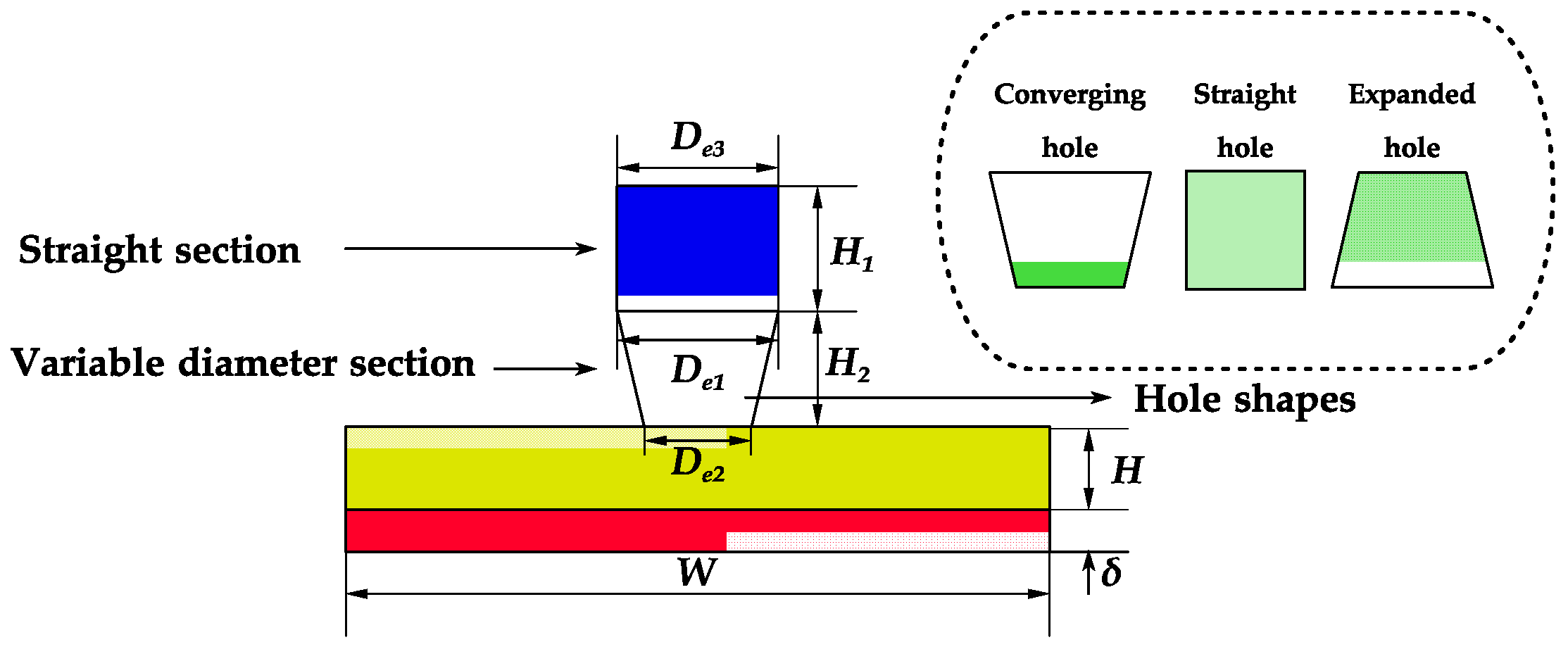
3. Variable-Diameter Holes

Variable-diameter holes, due to their geometric properties, can reduce the energy loss of the jet and accelerate the velocity of the fluid, thus creating a larger vortex when the jet hits the target surface, increasing the turbulence intensity and improving the heat transfer characteristics of the target surface. It is a modality that has been shown to influence jet impingement heat transfer and flow characteristics. Consequently, numerous scholars have conducted research into the impact of modifying the diameter of the jet orifice.
In a study by Colucci et al. [13], circular orifices and hyperbolic nozzles were compared. The findings indicated that hyperbolic nozzles exhibited superior heat transfer performance at smaller nozzle-to-plate distances and higher Reynolds numbers. Ram et al. [14] conducted an investigation into the three-dimensional steady-state flow parameters and heat transfer characteristics of a gas turbine lobed nozzle with leading-edge jet impingement cooling. They employed a computational fluid dynamics (CFD) simulation to analyse the cylindrical holes and converging conical holes. The target surfaces were maintained at a constant heat flux of 10,000 W/m2. Furthermore, steady-state simulations utilising the Reynolds-averaged Navier–Stokes equations and the kω-SST turbulence model demonstrate that the heat transfer performance is enhanced. This is evidenced by an increase in the Nusselt number by approximately 186% and a reduction in surface temperature by approximately 13% at Re = 23,000.
Zielinski et al. [15] proposed a novel variable-diameter hole for synthetic jets, whereby the diameter of the structure is observed to vary over time. The structure is capable of generating greater momentum and facilitates superior heat transfer in comparison to a fixed-diameter hole with an equivalent average size. To substantiate the enhanced functionality of the structure, particle image velocimetry (PIV) was employed to ascertain the momentum dynamics within the structure. The analysis employed both time-averaged and flavour-averaged techniques. In terms of the time-averaged analysis, the novel structure displays a markedly enhanced jet entrainment effect, exhibiting a fourfold increase in comparison to the fixed-diameter structure. In the context of phase-averaged analysis, the vortex field of the novel structure displays larger and more concentrated vortex loops, which suggests an increase in the maximum velocity, vorticity, and circulation of the jet.
In a numerical comparison and analysis of the heat transfer and flow characteristics of single jet impingement cooling, Xi et al. [11] considered three orifice configurations: converging holes, straight holes, and expanded holes. Figure 1 illustrates the geometry of these three hole types. The impact of the Reynolds number, outlet-to-inlet diameter ratio, and impingement height on confluence impingement cooling was examined. Based on this analysis, the fitted relational equations were developed to represent the influences, and the sensitivity of the cooling performance to the influences was evaluated. The results demonstrate that the convergent holes exhibit the most optimal heat transfer performance, yet the least favourable flow properties. The Reynolds number (Re) is a crucial factor influencing both the heat transfer performance and flow properties of the convergent holes. When Re is increased from 6000 to 30,000, the average Nusselt number increases by a factor of approximately 1.62 to 2.65, while the integrated thermal coefficient rises by a factor of approximately 1.58 to 2.45. These findings indicate that while the heat transfer performance of the convergent holes is the most efficient, their flow performance is the least optimal.
The majority of contemporary research in this field employs conical nozzles for variable-diameter applications, with a particular emphasis on the impact of the cone angle on the nozzle’s performance.
Shuja et al. [16] investigated the impact of cone angle on conical nozzles. Their study aimed to examine the influence of diverse gas properties on flow and heat transfer characteristics in the context of a variable cone angle, utilising air, oxygen, and argon as the work materials, respectively. The findings indicated that the heat transfer coefficient of air increases with the expansion of the cone angle of the nozzle.
Burak Markal et al. [17] tested a novel conical nozzle design comprising brass material and exhibiting conical coaxial characteristics. Four distinct cone angles, namely 0°, 10°, 20°, and 30°, were selected, along with a range of separation distances between the nozzle outlet and the target surface. The Nusselt number was employed as a parameter to investigate the heat transfer characteristics, whereas the wall pressure distribution was utilised as a parameter to investigate the flow characteristics. The findings indicated that the optimal heat transfer performance was attained with a cone angle of 20° under conditions of close collision. Additionally, the flow performance was influenced by the distance and angle between the nozzle and the target surface, while the cone angle exhibited a negligible impact.
Sathish et al. [18] investigated the Nusselt number and temperature distribution for three distinct cone angles (10°, 20° and 30°) while varying the Reynolds number within the range of 11,000 and 50,000. Their findings indicated that the optimal cooling effect was achieved with a 20° cone angle and that the Nusselt number increased in conjunction with a rise in the Reynolds number. Additionally, the temperature distribution on the wall surface exhibited a decline with the increase in the Reynolds number. With regard to the impact of additional parameters, Subrahmanyam et al. [19] demonstrated that a greater conical nozzle aspect ratio is conducive to reducing the junction temperature of silicon semiconductor chips.
In their study, Kansy et al. [20] evaluated the heat transfer performance of various nozzle configurations in terms of heat transfer area. Their findings indicated that the conical nozzle exhibited a more pronounced variation in heat transfer area at different inclinations compared to the reference nozzle. Talapati et al. [21] proposed parabolic and exponential nozzles based on conical nozzles and demonstrated that parabolic nozzles exhibit superior flow characteristics. Figure 2 provides a visual representation of the three nozzle shapes.
The flow and heat transfer characteristics of a target surface are dependent upon the geometry of the surface and the manner in which the jet structure is altered.
In their study, Shuja et al. [22] employed impingement cooling of a cylindrical cavity via a combined annular-cone nozzle, subsequently delineating the discrepancy in heat transfer coefficients at varying depths within the cavity.
Abdel-Fattah [23] analysed the flow characteristics of a high-velocity jet impingement cooling flat plate, as well as hemispherical and conical surfaces. Their findings indicated that for a given Reynolds number and nozzle-to-plate distance conditions, the wall geometry has a minimal impact on the pressure distribution across the surfaces. However, as the stagnation pressure increases, the maximum pressure also rises.
In recent years, research on variable-diameter nozzles has focused increasingly on structural optimisation. Chi et al. [24] employed a single-objective genetic algorithm to develop a predictive model of temperature distribution on the target surface, thereby identifying the optimal diameter for a variable-diameter orifice under conditions of uniform temperature. Das et al. [25] conducted parametric research on conical nozzles, identifying the parameter combinations that optimise heat transfer efficiency. Yang et al. [26] employed the response surface method to optimise the structure of conical nozzles, resulting in optimised nozzles that exhibited optimal combined heat transfer and flow characteristics.
In general, the current research methods for nozzle structure optimisation focus on the use of agent models combined with optimisation algorithms. The accuracy of the agent model construction and optimisation algorithms are the primary considerations in this type of optimisation problem.
The prevailing approach to nozzle structure optimisation entails the integration of an agent model and an optimisation algorithm. The accuracy of the agent model and the efficacy of the optimisation algorithm are the primary considerations in this class of optimisation problems.
The use of variable-diameter nozzles has been extended to other types of jets.
Whitt et al. [27] devised a method for generating pulsed jets with the objective of reducing junction temperature variations. This was achieved by means of a variable-diameter iris mechanism. Furthermore, variable-diameter nozzles are commonly employed in supersonic jets, given the ability of converging nozzles to accelerate the jet. Limayea et al. [28] investigated the impact of subexpanding acoustic jets with varying shapes of converging nozzles on the average Nusselt number of the wall. Sanjai et al. [29] examined the influence of distinct target plate tilt angles on the pressure peaks.
The preceding summary demonstrates that tapered nozzles are the most prevalent among variable-diameter nozzles. The primary design parameter influencing the performance of tapered nozzles is the taper angle. The optimal taper angle for a given nozzle structure can be determined through experimental or computational analysis. Furthermore, the performance of tapered nozzles is influenced by additional factors, including the working material, inlet flow, and Reynolds number (Re). The most commonly used parameters to characterise the heat transfer performance of tapered nozzles are the Nu and target surface temperature distribution. While other structural parameters also have some influence on the heat transfer and flow characteristics, this is not as significant as the taper angle. It is anticipated that the optimisation of the structure and parameters of the variable-diameter orifice will lead to their widespread use in other types of nozzle, following in-depth research into this area.

4. Irregularly Geometrical Holes

The utilisation of irregularly geometrical apertures represents a relatively common passive strategy employed to enhance jet impingement heat transfer. By modifying the geometry of the nozzle outlet, it is possible to enhance the mixing and entrainment characteristics of the jet. A review of the published literature on the subject revealed that these nozzles can be classified into four main categories: chevron nozzles, lobed nozzles, cross-shaped nozzles, and racetrack-shaped nozzles.

4.1. Chevron Nozzle

The chevron nozzle is based on the concept of a “sheet”, a jagged pattern located at the nozzle exit. Figure 3 provides an illustration of the geometry of a general chevron nozzle. This results in the formation of a counter-rotating vortex at the notch, which serves to enhance the process of flow mixing. Violato et al. [30,31] analysed the flow and heat transfer characteristics of a jet impinging on a flat plate at a Reynolds number = 5000, using circular and chevron nozzles with infrared thermography and time-resolved tomography particle image velocimetry (TOMO-PIV). PIV was employed to analyse the flow and heat transfer characteristics of jets impinging on a flat plate from circular and chevron nozzles at a Reynolds number = 5000. The results demonstrated that the chevron nozzle enhances the perturbation of the boundary layer on the plate, and that the turbulence kinetic energy of the chevron jet is twice as high as that of th CIJ at H/d = 3.9. At H/d = 2, the Nusselt number map of the chevron nozzle exhibits a distinct “star shape” compared to that of the circular jet, with the Nu level in the centre of the impact reaching a maximum of 40%.
Following the observation that chevron nozzles demonstrated superior heat transfer capabilities relative to circular jets under specific operational circumstances, there has been a significant increase in research efforts aimed at improving the performance of chevron nozzles. The initial step is to vary the number of chevrons. Horra et al. [32] demonstrated that the number of chevrons affects the heat transfer performance and uniformity of the nozzles. This was achieved by comparing jet nozzles with four and six chevrons, utilising numerical simulations. Vinze et al. [33] investigated the performance of chevron nozzles with 10 different chevron nozzles (number of chevrons n = 4, 6, 8; angle ϴ = 0°, 5°, 10°) on the local Nusselt number distribution of the jet impinging on a flat plate. Among the tested nozzles, the nozzle with n = 8, ϴ = 10° exhibited the best heat transfer performance, with a 25% increase in the local Nusselt number compared to the circular tube.
Du et al. [34] designed a novel elliptical chevron nozzle in conjunction with elliptical nozzles and observed that it enhanced fluid mixing in the stagnation zone, resulting in higher turbulence levels. Compared to circular jets, the elliptical chevron nozzle increased the Nusselt number in the stagnation point by 41%, as measured at the stagnation point.
The cooling performance of chevron nozzles on curved surfaces has also been the subject of recent research. Gao et al. [35] investigated the impingement of a jet on a conical concave surface of a chevron nozzle at an impingement distance of H/d = 2 and found that a significant heat transfer enhancement was produced near the concave leading edge. Guan et al. [36,37] examined the heat transfer performance of chevron jets at different Reynolds numbers (Re = 7800~39,400) and found that the enhanced heat transfer performance was more pronounced at a small Reynolds number. The enhanced heat transfer performance of the chevron jet was found to be more pronounced at low Reynolds numbers when the internal and external jets were in conjunction. Additionally, the conjugate heat transfer performance of the jet impinging on the conical concave surface exhibited a gradual decline with an increase in H/d. Lyu et al. [38] investigated the impact of a pulsed jet on a semicylindrical concave surface. Their findings indicated that, in comparison to a constant jet, the effect of changing H/d on the heat transfer performance was not significant.
In their experimental study, Lyu et al. [39] employed a synthetic jet generated by a piston-driven actuator to investigate the performance differences between a chevron tube and a circular tube at five operating frequencies (5 Hz, 10 Hz, 15 Hz, 20 Hz, and 25 Hz) and dimensionless nozzle-to-plate distances of H/d = 2~8. The results corroborate the hypothesis that chevron nozzles enhance the heat transfer characteristics of synthetic jets, and that the frequency magnitude exerts a significant effect. The chevron nozzle has been the subject of considerable research into the synthetic jet [40,41,42], which provides a basis for the future practical engineering applications of the chevron nozzle.

4.2. Lobed Nozzle

The lobed nozzle was first applied to a diffuser in the aerospace field, and it was shown [43] that the large-scale vortices it generates are able to break down into smaller but not weaker vortices as they move downstream, thus enhancing both large-scale and small-scale mixing. Martin et al. [4] first investigated the local heat transfer performance for cooling the air jets emitted from the three- and four-lobed nozzles studied and found that at a high Reynolds number (Re ≥ 15,000), the three-lobed nozzle had better heat transfer performance when H/d ≤ 1 and the four-lobed nozzle had better performance when H/d > 7. Panse et al. [44] compared the jet heat transfer characteristics of the three-lobe, four-lobe, and six-lobe nozzles at different H/d. It was found that the axial switching effect of the Nusselt number maps was significant at H/d = 1.6, while it gradually approached that of the circular nozzle as H/d increased.
Sodjavi et al. [12] designed a six-lobed hemispherical nozzle (DO/H), called a daisy nozzle, and compared with a reference circular jet, the maximum wall shear rate was improved by 93% and the maximum local mass transfer coefficient was improved by 35%, verifying the good mass transfer performance of the lobed nozzle. Lyu et al. [45] investigated the heat transfer characteristics of the lobed nozzle impinging on planar and concave surfaces at smaller distances, respectively, and found that the maximum Nusselt number of the stagnation zone on planar surfaces was increased by 25% compared to the circular jets, but on curved surfaces, due to curvature, it was reduced by 20–30% compared to the circular jets.
In addition to studies comparing the performance of nozzles with different lobe numbers, He et al. [46,47] compared lobed nozzles with different nozzle centre offsets (a) and nozzle radii (b). Figure 4a illustrates the specifics of the designed nozzle, while Figure 4b depicts the computational domain. The TSP measurements showed that a/b = 0.8, 1.15 had optimal heat transfer performance at H/d = 2, 4, respectively. By comparing the results of large eddy simulation (LES) between different parameters, it was concluded that the nozzle with a/b = 0.8 has the strongest transient flow influence and the largest average Nusselt number in the region of 1 < r/d <4. Subsequently, using a combination of TSP and PIV, it was concluded that the average Nusselt number gradually increased with a/b in the range of r/d < 0.5 at H/d = 4 and continuously decreased in the range of 2 < r/d < 4. Meanwhile, the degree of turbulence in the wall jet region also increased, as measured by PIV. In addition, they also used two-camera laminar particle image velocimetry (tomo-PIV) to analyse the flow field characteristics of the lobed nozzle at different st values, and found that the fluid bubbles in the large-scale axisymmetric structures of st = 0.51 and 0.65 broke up, which provided further profiling of the flow field of the lobed nozzle.
In recent years, with the increasing interest in synthetic jets, Lyu et al. [48,49] proposed the use of the lobed nozzle in a synthetic jet and designed a new petal-shaped lobed nozzle. Figure 5 illustrates three new hole shapes. They concluded that the six-lobe nozzle used showed superior heat transfer performance in most cases, but the heat transfer efficiency was drastically reduced at the concave target surface. By means of large-vortex simulation, they further revealed the influencing factors of the impingement cooling of the concave plate: the concave surface has a confining effect on the jet and creates a reflux zone during circulation.

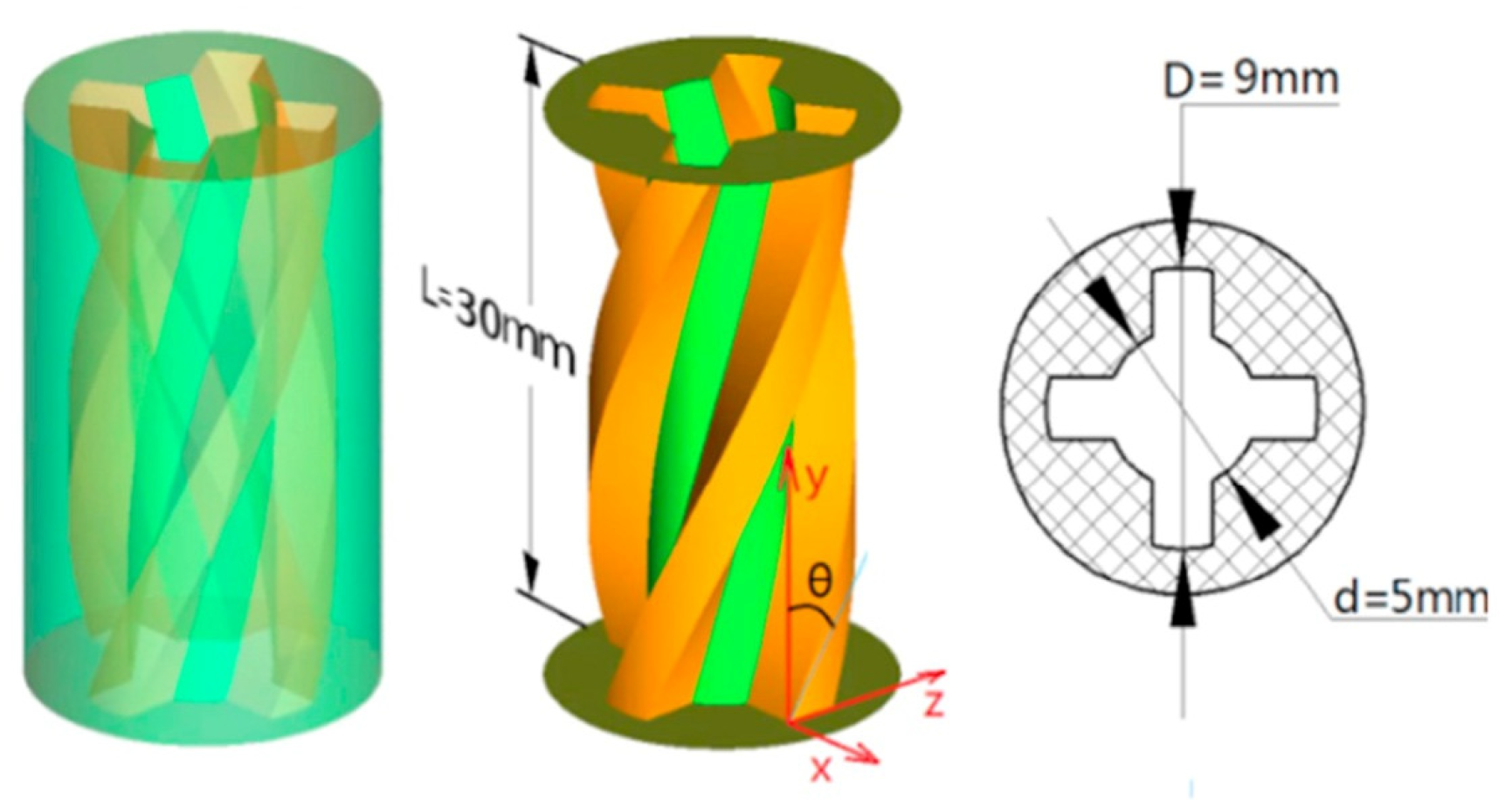
4.3. Cross-Shaped Nozzle

The design principle of the cross nozzle is similar to that of the lobed nozzle. As the designation implies, the apparatus is a nozzle with a cross-shaped outlet. Figure 6 illustrates the orifice of the cross-shaped nozzle. Oyakawa et al. [3] installed a cross nozzle at the end of a cylinder, and first analysed the heat transfer performance for a jet impinging on a flat plate in the shape of a cross by using the oil film method to visualise the flow and infrared thermometry to show the isothermal lines. The axial switching phenomenon on the target plate was found, and the core area of the free jet was prolonged downstream compared with that of a circular jet, and the isothermal lines and the distribution of heat transfer coefficients were better matched, and the local heat transfer coefficients were also larger downstream. Trinh et al. [50] focused on the three-dimensional flow characteristics of the jet, which are significantly different from those of a circular tube nozzle at small nozzle-to-plate distances (H/d < 2).
Kristiawan et al. [51] investigated the wall shear rate and mass transfer rate of a cross-jet at a Reynolds number of 5500 and a nozzle-to-impact area of 1 to 5 for an impacted flat plate, and compared with the circular convergent nozzle proposed by Chin and Tsang [52], the wall shear rate was 175% higher than the reference nozzle at H/d = 1; the difference in shear rate between the two types of nozzles gradually decreased with the increase in H/d.
Rau et al. [53], for local single-phase and two-phase heat transfer, experimentally and numerically simulated that the local heat transfer coefficient of the cross-jet is 1.5 times higher than that of the circular jet for the same orifice area, while the pressure drop is only 1.1 times higher.
To achieve more efficient mass transfer performance, Sodjavi et al. [54] used a hemispherical cross-hole nozzle (CO/H) to extend the shear layer at the exit of the jet. At a Reynolds number = 5620, the average Sh of CO/H was improved by 25% over the reference convergent jet, resulting in superior mass transfer characteristics than the cross-hole nozzle on the plane (CO/P).
Trinh et al. [55] studied similar structures with an equivalent diameter = 14 mm at different Reynolds numbers (23,000 < Re < 45,000) and orifice plate distances (1 < H/d < 5) and showed that the velocity distributions at the outlet of CO/H and CO/P jets are quite different, with CO/H affecting the heat transfer efficiency due to the fact that it entrains more ambient work mass in the free jet region and with a Nusselt number lower than that of the hemispherical circular orifice nozzle.

4.4. Racetrack-Shaped Nozzle

Through the study of rectangular and elliptical jets, it has been found that an elongated shape of the jet orifice allows a larger stagnation zone on the target surface and promotes increased turbulence intensity, thus improving heat transfer capability, and thus a “racetrack” shape of the jet orifice has been proposed. It has been shown to be superior to a circular orifice (Taslim [56]) and is now widely used for impingement cooling of the leading edge of turbine blades.
Jordan et al. [57] compared the impingement cooling performance of a single row of circular and racetrack orifices of the same hydraulic diameter at Re = 11,500~40,000. Jordan et al. [58] investigated the effect of cross-flow based on the results [57] and found that the jet impingement cooling effect on the leading edge of the turbine airfoil decreases as the velocity of the cross-flow increases.
To investigate the effect of turbine rotation on jet cooling, Harmon et al. [59] conducted impingement cooling experiments with racetrack holes in a rotating channel and concluded that the racetrack holes improve the uniformity of heat transfer as the number of rotations increases. Wang et al. [60] combined a double vortex chamber with racetrack holes, which effectively reduced the effect of the Coriolis force generated by the rotations.
Harmon et al. [61] investigated the effect of jet plate thickness on jet cooling, which has received less attention, and found that the cooling effect decreases with the increase in jet plate thickness. Kulkarni et al. [62] experimentally verified the effects of previous studies and proposed a prediction model for the correlation between parameters such as Reynolds number, nozzle to plate distance, and heat transfer coefficient and pressure drop coefficient. Most of the prediction errors are within 10%, which can provide a basis for designers to predict the correlation results.
The results of the literature survey indicate that each nozzle exhibits superior heat transfer characteristics in comparison to the circular nozzle, particularly in the context of jet cooling applications. The flow field characteristics of these nozzles are analysed in detail through a combination of experimental and numerical simulation techniques. A comparison of several nozzles reveals that the chevron nozzle demonstrates the most significant improvement in heat transfer capacity when compared to the reference nozzle. In contrast, the cross-shaped nozzle shows relatively little improvement in heat transfer performance. Both the lobed nozzle and the cruciform nozzle have been employed to enhance mass transfer characteristics due to analogous design principles. In contrast, the racetrack nozzle has been the subject of more investigations with respect to the performance of its array. Both the chevron nozzle and the lobed nozzle have been optimised in terms of the number and angle of the representative structures based on their geometrical characteristics. Given the relative complexity of the geometrical structures, there is the potential for further performance improvements. Further possibilities exist. The curvature of the target surface has a significant effect on the heat transfer characteristics of several nozzles, and further investigation is required to elucidate this phenomenon.

5. Swirl Nozzles

Although jet impingement heat transfer has been demonstrated to be an extremely effective method for improving heat transfer, the rapid reduction in the Nusselt number’s distribution in the stagnant zone in the radial direction results in a non-uniform temperature distribution on the wall surface, which has a detrimental impact on the structure. The rotating impingement jet and the conventional jet exhibit an additional tangential velocity compared to the conventional jet, which can enhance the flow mixing, strengthen the intensity of turbulence, and also increase the contact area with the target surface. Consequently, the rotating jet is applied to jet cooling in order to improve the uniformity of the heat transfer. The existing research on the generation of a rotating jet nozzle can be broadly classified into several categories. These include the addition of a twisted belt, a spiral rod, and a guide vane.

5.1. Inserting Twisted Tape

In their study, Wen et al. [63] inserted a longitudinal rotating strip into a circular tube and designed two nozzles for generating rotating jets. These were tested at Reynolds numbers Re = 500~27,000 and jet-to-plate distances H/d = 3~16. The results demonstrated that the heat transfer performance was enhanced in all cases relative to the circular tube nozzles, with the majority of the Nusselt number enhancements at the stagnation point reaching approximately 5%. Fu et al. [64] incorporated a standard circular tube nozzle with a twisted tape. The comparison revealed that the heat transfer coefficient distribution on the target surface exhibited greater uniformity, the heat transfer coefficient at the stagnation point of the rotating shock jet was slightly lower, and the location of the maximum heat transfer coefficient exhibited a shift outward.
Kunnarak et al. [65] embedded a four-channel twisted tape in a circular tube and investigated the effect of the distance H/d from the jet to the target plate at a constant Reynolds number of 5000. The geometric details of the designed four-channel twisted tape are shown in Figure 7. Their findings indicated that there is an optimal mean heat transfer distribution at H/d = 2, while the difference in heat transfer performance between rotating jets and MCIJ decreases with an increase in H/d. Ianiro et al. [66] employed Tomo-PIV to examine the transient flow field characteristics of a rotating jet and observed that the rotating shock jet exhibited smaller vortices in both the inner and outer shear layers, resulting in deeper turbulent penetration within the core of the jet.
In addition to the Reynolds number, nozzle-to-plate distance, and other influencing factors, scholars have also modified the parameters of the twisted tape in order to conduct a more comprehensive study. Nuntadusit et al. [67] added a twisted tape made of stainless steel, twisted around the longitudinal axis by 180° in a circular tube, and employed a visual method to compare the flow pattern of rotating jets generated by the nozzles inserted with different twisted tapes. They then analysed the results in order to ascertain the extent to which the free jet increases gradually with the number of revolutions. Nanan et al. [68] conducted an experimental study to measure the Nusselt number distribution of a target flat plate with varying twist ratios (γ/w = 3, 4, 5, 6, where γ is equal to 180° divided by the length of the tape and w represents the width of the tape), jet-to-plate spacing (H/d = 2~8), and Reynolds numbers (Re = 4000~16,000). The average Nusselt number of the plate is at its greatest when the twist ratio is at its maximum.
Salman et al. [69] reported that the rotating shock jet exhibited the most uniform radial Nusselt number distribution at the maximum twist ratio. They also concluded that the ST-k-ω turbulence model in CFD modelling was the closest to the experimental data. Kumar et al. [70] expanded the range of variation of the twist ratio for the twisted zone (γ/w = 2, 3.2, 4.5, 7.5). In comparison to previous studies, this present investigation involved experimentation under a range of Reynolds numbers (500~3000) and jet-to-plate distances (H/d = 1~4). Their findings indicate that the heat transfer performance of the rotating impact jet does not exhibit a monotonically increasing trend with an increase in the twist ratio. The optimal ratio was identified as 4. The optimal ratio for enhanced heat transfer is 5. Zeiny et al. [71], on the basis of exploring the effect of the twist number, varied the roughness by placing obstacles in the plane of the impingement. The results demonstrate that the variation of the roughness produced some effect.
In recent years, considerable attention has been devoted to the arrangement of the twisted bands. Khanmohammadi et al. [72] further investigated the impact of incorporating either a single twisted band or a double twisted band in the nozzle, based on the structural configuration proposed by Wen [63], with a variation in twist ratios within the range of 2.5–3.5. Their results demonstrated that the double twisted bands exhibited superior heat transfer characteristics, particularly at low twist ratios. Conversely, the single twisted bands exhibited a lower pressure drop. Furthermore, a multi-objective optimisation algorithm was employed to identify the optimal values for each parameter of the twisted belt. Eiamsa-ard et al. [73] conducted a comparative analysis of isotropic and contrarotating double twisted belt nozzles, identifying that the performance of these two types of nozzles exhibited distinct advantages and disadvantages at varying Reynolds numbers and twist ratios. Both Nasirzadeh [74] and Ajour [75] proposed novel twisted belt arrangements that demonstrated enhanced performance compared to the conventional arrangement.
In the context of jet impingement cooling, air and water are the most commonly utilised fluid media. These two materials are also the most logical choices for the work mass, given the ease of obtaining the raw materials and the cost of the materials. However, in certain fields, the use of specialised fluids is necessary for effective jet heat transfer, with bonded nozzles frequently employed to enhance performance. Hindasageri et al. [76] conducted a comparative analysis of the heat transfer performance of a rotating flame jet at varying Reynolds numbers, while Sun [77] and Wongchareea [78] utilised a mixture of nanofluids as a workhorse, additionally considering the impact of varying nanofluid mixing ratios in comparison to other studies.

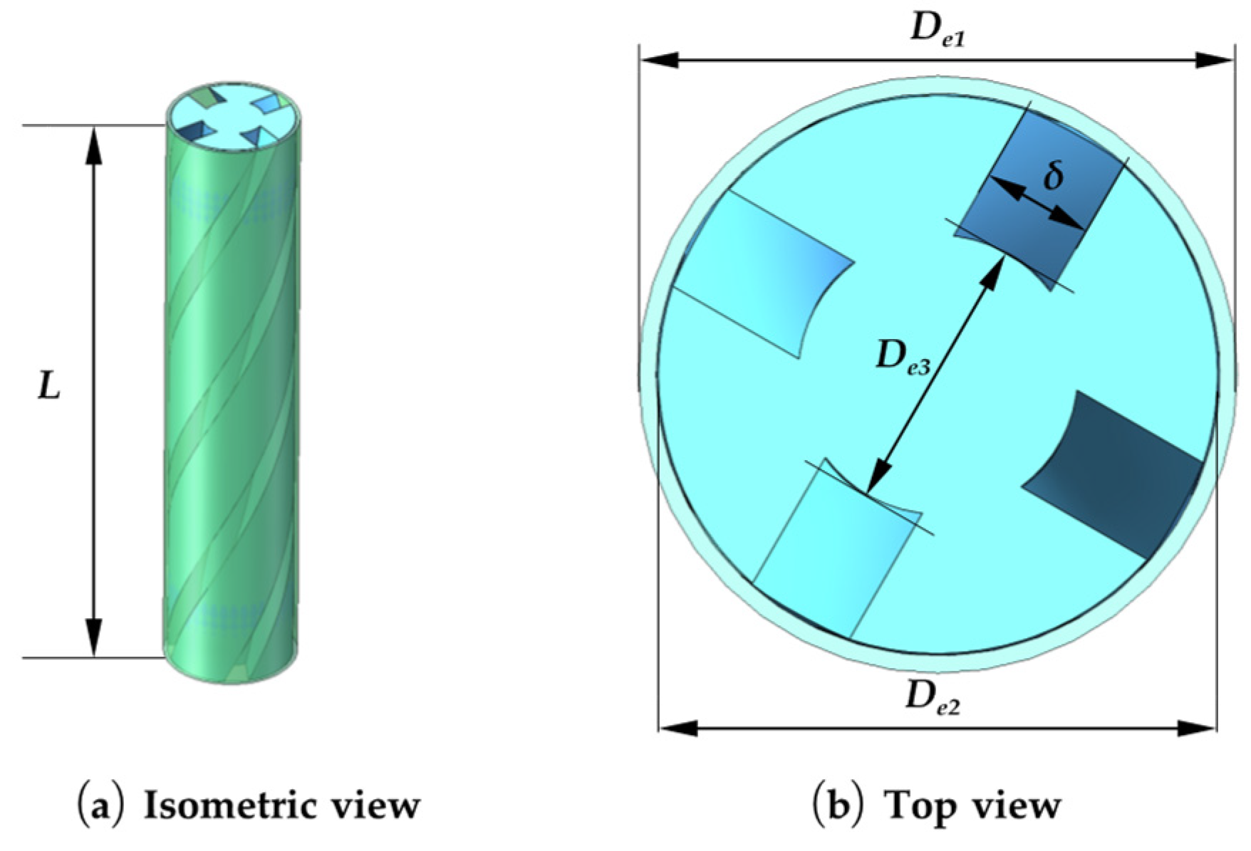
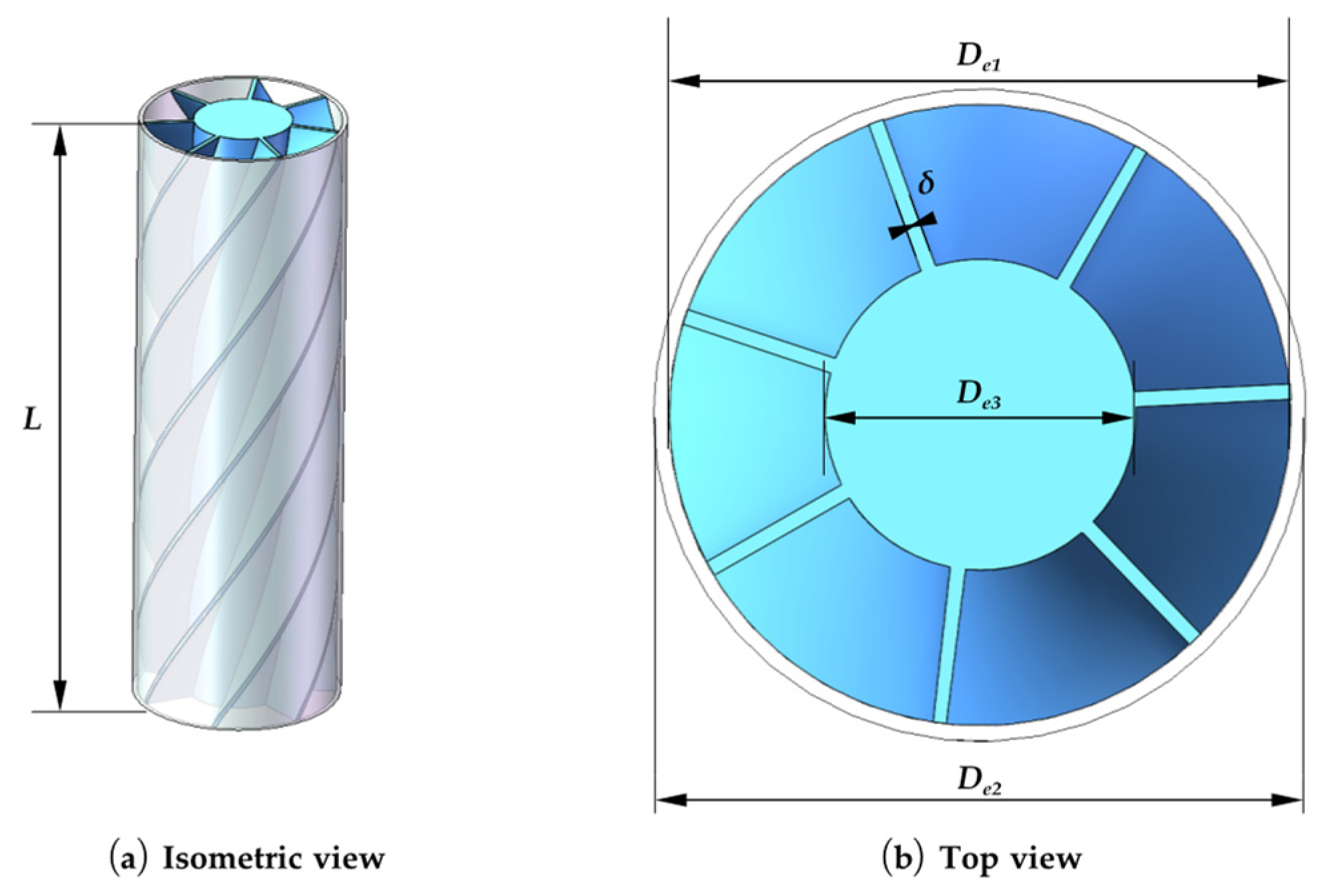
5.2. Installing a Spiral Rod

The insertion of a vortex generator in the form of a helical rod into a circular outer tube facilitates a more uniform heat transfer distribution by obstructing the fluid in the centre of the tube while intensifying the turbulence intensity in the region away from the stagnation point. Huang et al. [79] pioneered the utilisation of this technique in jet cooling. A vortex generator was constructed from a cylinder with an inner diameter matching that of the circular tube, featuring four oblique narrow slots on the surface. This was then inserted into the outlet of the circular tube, resulting in the formation of a rotating jet. The performance of this vortex generator was then compared with that of a multi-channel shock jet and a conventional shock jet. The findings demonstrate that the radial thermal homogeneity of the rotating jet was markedly enhanced. The direction of the rotating jet was varied by continuously changing the inclination angle of the narrow slot. The optimal results were obtained via comparison. Bilen et al. [80] designed a vortex generator with a larger cross-sectional area share of the channel than that of Huang [79]. The results obtained further verified the conclusions. The geometric details of the designed swirling generator are shown in Figure 8.
In their study, Lee et al. [81] investigated the impact of varying nozzle-to-plane distances and the number of spins on the heat transfer efficiency of a rotating jet. Senda et al. [82] employed laser Doppler velocimetry (LDV) to examine the flow characteristics of a vortex impinging on a flat plate. Their findings revealed the formation of recirculation flow in the stagnant zone, which in turn influenced the overall heat transfer effectiveness. Bakirci et al. [83], in their study, designed a vortex with a constant helical airway. The heat transfer characteristics of the jet produced by the vortex generator with different swirl angles (ϴ = 0°, 22.5°, 41°, 50°) were evaluated by liquid crystal technique, and the results demonstrated a strong correlation between the surface temperature distribution uniformity and the swirl angle. Furthermore, the results indicated that the uniformity of the temperature distribution is optimal when the swirl angle is 50°.
Fenot et al. [84] investigated the impact of thermal jets on heat transfer efficiency, finding that the vortex effect increases the entrainment of ambient air and consequently reduces the efficiency of heat transfer. Markal et al. [85] examined the influence of varying total flow rates on heat transfer, demonstrating that an increase in total flow rate enhances both the heat transfer rate and the uniformity of radial heat distribution. Chouaieb et al. [86] explored the optimal location of the vortex generator in a circular tube for diverse intended applications. Singh et al. [87] conducted an analysis of the flow and heat transfer characteristics of a counter-rotating double-rotating flame jet at varying Reynolds numbers and spacing distances.
Illyas et al. [88,89] conducted an analysis of the nozzles embedded with single-, double-, and triple-helical rods, respectively, and introduced the Multi-Response Performance Index (MRPI) as an evaluation metric. This was achieved by performing ANOVA for different influencing factors at different nozzle-to-plate distances. The results demonstrate that the MRPI values indicate the superior overall performance of the double-helical rod nozzles. The analysis of variance (ANOVA) revealed that the nozzle-to-plate distance had the most significant impact on nozzle performance.

5.3. Inserting Guide Vane

Alekseenko et al. [90] employed the stereoscopic PIV technique, coupled with sophisticated pre-processing and post-processing algorithms, to assess the dissimilarities in dissipation rates and velocity moments between vortices generated by circular tubes incorporating guide vanes and conventional jets impinging on a flat plate under fixed Reynolds number conditions. Their findings revealed that rotating jets exhibit heightened dissipation rates, accelerated velocity decay, and that an augmentation in the intensity of the vortices influences the alteration in the extent of the reflux zone. Nozaki et al. [91] demonstrated that an increase in swirl intensity has a beneficial effect on local heat transfer.
Yang et al. [92] embedded a helical guide vane in an annular nozzle with the objective of analysing the effect of the introduced vortex motion on the wall pressure and heat transfer characteristics of an annular jet. In order to achieve this, the Reynolds number was kept fixed while the distance from the nozzle to the impact plate was varied. The findings indicate that, in comparison to the annular jet, the rotating jet exhibits a markedly reduced wall pressure in the central region. In the vicinity of the stagnation zone of the impingement plate of the rotating jet, the heat transfer coefficient is observed to be markedly inferior to that of the non-rotating jet at relatively minor separation distances. As the separation distance increases, the local heat transfer distribution becomes increasingly uniform. Figure 9 shows the designed nozzle with embedded guide vanes.
Brown et al. [93] observed that rotating jets exhibited a higher Nusselt number than non-rotating jets at low jet heights. Ahmadvand et al. [94] evaluated three distinct blade angles relative to the axial direction (30°, 45°, and 60°), employed computational fluid dynamics (CFD) to simulate the fluid flow characteristics, and conducted experiments under uniform heat-flow conditions to validate the simulations with experimental results. The findings indicate that the heat transfer efficiency rises in conjunction with an increase in blade angle, with the overall Nusselt number increasing by between 50% and 110%. Yang et al. [95] conducted further research into the performance of rotating jets generated by short blades, building upon the aforementioned study. Their findings revealed that the heat transfer distribution is more inhomogeneous in comparison to annular jets.
Liu et al. [96] analysed the flow characteristics of the vortex by identifying and measuring the liquid retention rate through a self-organising neural network (SONN) and a cumulative probability density function (CPDF). Zerrout et al. [97] investigated the effect of a multi-rotating jet nozzle system on the impinging flat plate. Their findings indicated that, at jet heights between 4 and 6, reverse rotation of the central nozzle facilitates a uniform distribution of the flat plate temperature.
The aforementioned vortexers exhibit a high cooling efficiency and heat transfer uniformity. However, the heat transfer at the centre of the stagnation point area of the impinging surface is suboptimal due to the clogging effect induced by the vortexer’s geometrical features. The aforementioned issue can be effectively resolved by removing the portion of the vortexer inserted into the nozzle while maintaining the spiral channel. Based on this concept, Xu et al. [10,98] devised a novel nozzle design with internal threads. Figure 10 shows the internal geometry of this threaded nozzle. They employed the RNG k-ω turbulence model to simulate the three-dimensional jet impingement process, which demonstrated that the heat transfer rate at the centre of the stagnation zone was superior to that of the multi-channel impingement jet. Additionally, the cooling uniformity in the radial direction was enhanced with an increase in the vortex angle. Yang et al. [99] conducted a comparative analysis of the flow and heat transfer characteristics of the aforementioned nozzles within a specified range of Reynolds numbers and across varying vortex angles. Their findings revealed notable performance discrepancies among the nozzles under different evaluation criteria, offering valuable insights that can inform the future design of vortexers tailored to specific requirements.
The three swirl nozzles display enhanced heat transfer uniformity in comparison to the reference nozzle, which is primarily characterised by Nuave. However, the Nu values are slightly diminished in the centre of the stagnation zone as a consequence of the clogging of the central region of the nozzle by the helical rod and the guide vane. Even for a given nozzle type, there are discrepancies in the geometric models used in the literature, making it difficult to make accurate comparisons of performance between different nozzle types.
In the case of nozzles that are embedded with twisted tapes, they are currently classified into two distinct categories: single and double tapes, which are differentiated based on the number of tapes present. Nozzles with single tapes exhibit a lower pressure drop, although their heat transfer performance is relatively poor. This is due to the fact that the number of distinct tapes employed determines the intensity of the cyclonic flow, which in turn affects the uniformity of heat transfer. Nevertheless, an increase in tape volume results in greater energy loss of the fluid, necessitating the introduction of additional metrics for comprehensive evaluation of this type of nozzle.
A review of the published literature reveals that the twist ratio, swirl angle, and blade angle are the primary factors influencing the uniformity of heat transfer for the three types of nozzle. However, the impact of other geometrical parameters remains underexplored. The future research trend in this field will be the application of optimisation algorithms to enhance the performance of these nozzles

6. Special-Shaped Hole Arrays

In the majority of engineering applications, arrays of jets are employed with the objective of achieving the cooling of the entire heat transfer surface. In contrast to a single-hole nozzle, each jet in an array nozzle is exposed to the corresponding mixing zone. The coil suction effect generates a free jet zone, which causes the neighbouring two sides of the jet to interact with each other. This results in more complex and variable heat transfer and flow characteristics. Additionally, numerous scholars have conducted research on array jets. The majority of studies focus on the geometrical characteristics and configuration of the nozzles.

6.1. Impact of Nozzle Geometry

The effect of varying the geometry of the jet holes is a topic of interest in the majority of studies. Arjocu et al. [100] conducted an analysis of the flow and heat transfer characteristics of a three by three elliptical-hole jet array impinging on a flat plate. This was achieved by varying the aspect ratio of the ellipse at low Reynolds numbers (Re = 300 to 1500). This was achieved through the utilisation of measurements with PIV and hot-wire anemometers, as well as a transient thermochromic liquid crystal method. The flow structure within the central jet region was visualised, and it was found that the average heat transfer is inversely proportional to the aspect ratio. This also corroborates the effect of changing the nozzle geometry on the heat transfer characteristics of the array jet. Attalla et al. [101] compared the heat transfer performance of circular and square nozzles with different nozzle spacing and nozzle-to-plate distances. The results demonstrate that the heat transfer uniformity of square nozzles is significantly higher than that of circular nozzles. Furthermore, the nozzle-to-plate distance has a lesser effect on the Nusselt number, whereas the nozzle spacing plays a significant role in determining the heat transfer uniformity.
In order to achieve optimal heat transfer performance while minimising pressure drop, Whelan et al. [102] chamfered the nozzles and evaluated the overall performance of the nozzles using a figure of merit (FOM) for a square jet array consisting of 45 nozzles in the Reynolds number range of Re = 300~10,000. Subsequently, the inlet and outlet shapes of the nozzles were tested, resulting in a notable enhancement in overall performance. Marzec et al. [103] conducted numerical simulations to examine the effects of varying orifice shapes in single-row variable-diameter orifice jet arrays. Their findings revealed that the orifice shape exerts a considerable influence on the Nusselt number. Subrahmanyam et al. [19] explored the potential of conical nozzle arrays for cooling electronic devices, with a particular emphasis on the impact of varying aspect ratios. Their results demonstrated that high aspect ratios can significantly enhance the overall performance of the nozzles. These findings indicate that high aspect ratio nozzles can enhance the Nusselt number and heat transfer coefficient and can effectively mitigate the temperature rise in silicon semiconductors.
In their experimental analysis, Yamane et al. [104] investigated the heat transfer and flow field characteristics of a three by three lobed nozzle square array at Re = 4680 with varying injection distances and nozzle spacings. They compared these results with those obtained from an array of circular nozzles arranged in a similar configuration. It was observed that the local Nusselt number in the intermediate region between the four lobed nozzles exhibited a notable increase at smaller H/d and larger nozzle spacing. In a subsequent study [105], local flow fluctuations induced by the jet shape were identified in the region between neighbouring jets using a microflow sensor. This was identified as the cause of the enhanced heat transfer observed in the previous study.
Wannassi et al. [106] devised a combined array of swirling flow and CIJ, wherein the rotating jets were generated by nozzles incorporating guide vanes. Figure 11 shows details of this combination array. To analyse the heat transfer characteristics, they employed a combination of numerical and experimental methods, while oil film visualisation techniques were used to observe the flow patterns. The results demonstrate that the incorporation of rotating jets does not significantly impact the distribution of the heat transfer coefficient. However, the rotating jets do influence the change in heat transfer coefficients of the surrounding direct-flow jets. Furthermore, the impact of rotating jets on the flow pattern can be discerned. Xu et al. [107] also concentrated on the array of rotating jets. In order to simulate impingement cooling on the leading edge of a curved turbine blade, they examined the heat transfer characteristics of a single row of rotating jets against a semi-cylindrical concave surface at varying jet spacings. The maximum increase in the average Nusselt number is 24.6% in comparison with the circular impingement jet, while the Nusselt number in both the radial and axial directions decreases with the increase in the jet spacing.
Modifying the geometry of the target surface is a common practice in the study of single jets, and it is also a crucial aspect in the analysis of jet arrays. Lyu et al. [108] employed an infrared camera to assess the temperature in the context of impingement cooling for a single row of chevron nozzles with varying curvatures of the concave surface, at different Reynolds numbers (Re = 5000, 10,000, 15,000), and at varying dimensionless nozzle-to-plate distances (H/d = 1~8). The average Nusselt number was then calculated to facilitate an in-depth analysis of the heat transfer characteristics. The average Nusselt number was calculated in order to analyse the characteristics of heat transfer. The findings indicate that the curvature of the concave surface is the primary determinant of the heat transfer performance, with a higher longitudinal average Nusselt number observed along the front of the concave surface with a high curvature.

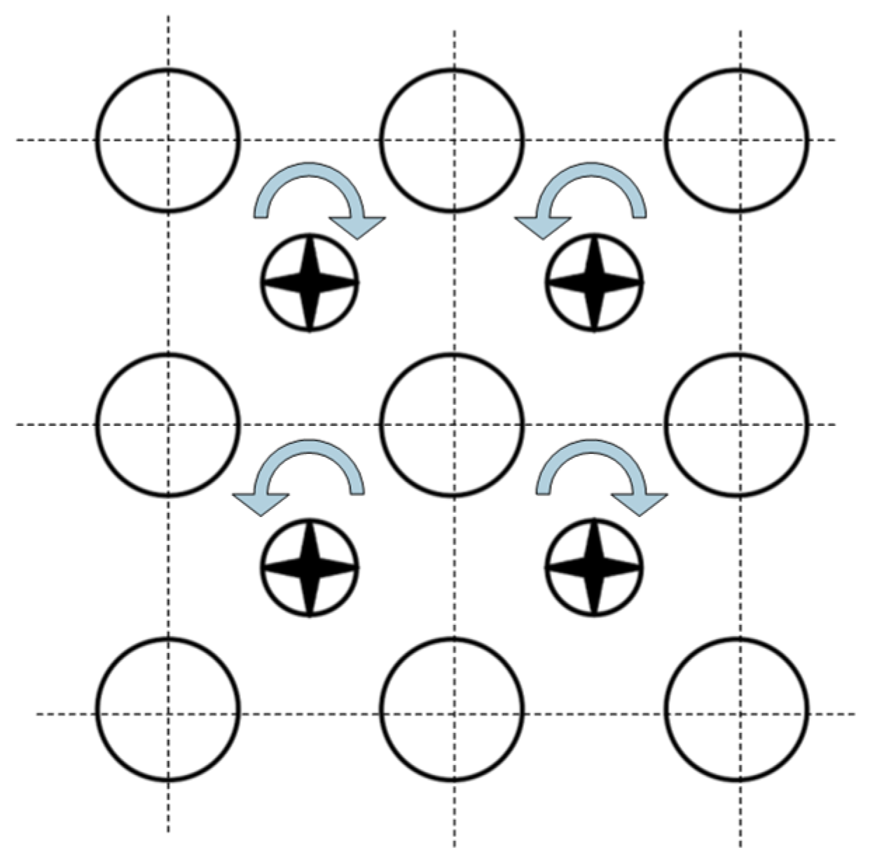
6.2. Impact of Array Method

Modifications to the jet orifice configuration influence the intermixing of fluids between neighbouring jets, resulting in the formation of diverse vortex structures and intricate flow patterns. Consequently, the dissimilarities in the attributes of disparate jet array techniques have been extensively examined in numerous academic publications. One method of altering the jet arrangement is to modify the direction of the main axis of the jet holes. Wen et al. [109] employed numerical simulation to arrange nozzles with varying geometries, with the nozzle’s centre of gravity positioned at a consistent location but the main axis direction altered. This approach was applied to simulate rapid cooling in a high-speed vehicle. The simulation results demonstrate that the distinct nozzle configurations result in a more spatially complex flow field and exert a considerable influence on the heat transfer characteristics. Dano et al. [110,111] examined the velocity field of a seven by seven concave elliptical jet array with orthogonal decomposition and vortex detection algorithms for the jet aperture main axes in parallel and perpendicular to the cross-flow direction, respectively, and delineated the impact of the axial switching of the jet aperture on the kinetic energy of the vortex. Figure 12 illustrates the relationship between the cross-flow direction and the position of the main axis of the holes.
In light of the fact that the cross-flow effect has an impact on the efficiency of jet cooling, Nuntadusit et al. [112] conducted a comparative analysis of linear and staggered arrangements with the objective of identifying the arrangement that is most effective in mitigating the adverse effects of cross-flow. The researchers employed thermochromic liquid crystal sheets (TLCs) and oil film techniques to analyse the heat transfer and flow characteristics of the impinging surfaces of raceway-type jet hole arrays with varying aspect ratios. The findings indicate that the linear configuration is less susceptible to cross-flow effects, with the jet linear array at an aspect ratio of 4 exhibiting optimal performance. It should be noted that the results presented here are not universally applicable to different nozzle shapes and cooling methods. Fawzy et al. [113] applied a staggered arrangement of conical nozzles to simulate the cooling inside and outside of lobed nozzles. Their findings indicated that the staggered arrangement had the largest overall Nusselt number among all array methods.
There is a paucity of studies on special-shaped orifice arrays, with the majority of existing research focusing on special-shaped nozzles arranged in a square configuration. The objective of these studies is to evaluate the impact of diverse nozzle geometries. Variable-diameter hole arrays represent the most prevalent category of special-shaped hole arrays. The correlation between H/d and target surface Nu is less pronounced in comparison to that observed for single jets. The jet spacing represents the primary geometrical parameter influencing the uniformity of heat transfer. The enhanced performance of special-shaped holes in comparison to circular holes is more pronounced in terms of heat transfer uniformity. However, the maximum heat transfer coefficient enhancement is relatively modest, which presents a challenge for the future development of special-shaped hole arrays.
The orientation of the main axis of the special-shaped holes will have an impact on the jet cooling effect due to cross-flow. The extent to which different array methods are influenced by cross-flow is contingent upon the specific geometry of the nozzle.

7. Conclusions and Outlook

Jet impingement cooling represents one of the most prevalent techniques employed to enhance heat transfer. This paper provides a comprehensive overview of the various specialised nozzle shapes currently employed for jet cooling. Table 1 offers a summary of these special-shaped holes.
In comparison to the more prevalent ordinary circular nozzles, special-shaped nozzles exert an influence on the momentum of the jet, intensify the turbulence within the jet, generate more pronounced perturbations in the target surface boundary layer, and augment the heat transfer coefficient within the collision zone of the jet, thereby affecting the impingement cooling performance. Furthermore, an increase in the surface roughness of the target and optimisation of the geometrical parameters of the special-shaped nozzle will result in an enhancement of the heat transfer and flow properties of the jet emitted from the SSHs. This will have a positive effect on, among other things, the uniformity of the heat transfer distribution and the mass transfer rate. The following specific conclusions may be drawn:
(1)
The variable diameter nozzle is a relatively simple item to produce, which has resulted in it being used more widely than other special-shaped nozzles. Among these, the conical nozzle is the most prevalent type of variable-diameter nozzle, and the cone angle represents the primary determinant of its performance. The current research indicates that a 20° cone angle has the most effective cooling effect; however, it is not yet clear whether this is the optimal angle. The main method used to optimise the nozzle structure is the agent model combined with an optimisation algorithm.
(2)
The implementation of nozzles with specially shaped jet holes has been demonstrated to markedly enhance the heat transfer characteristics in comparison to those of circular jets, particularly at smaller distances between the nozzle and the plate. The correlation between different geometric parameters and nozzle performance has been less well studied than the optimisation of nozzle performance itself, despite the latter being a well-researched topic. Furthermore, there is a paucity of research examining the parameters that characterise flow properties, such as pressure drop.
(3)
The main special-shaped nozzles for generating rotating jets have been shown to provide a significant improvement in the uniformity of heat transfer distribution, particularly in terms of the local Nusselt number distribution in the radial direction, in comparison to the direct current jet. In the case of nozzles incorporating Nusselt elements, the number of twisted bands and the twist ratio represent the primary parameters influencing their performance. In the case of nozzles embedded with helical rods and guide vanes, the current studies have concentrated on examining the impact of the swirl angle and lobed nozzle angle. However, this research has not yet fully addressed the subject. The complexity of its structure has resulted in a relatively low current usage of optimisation algorithms.
(4)
Currently, there is a paucity of studies on special-shaped hole arrays, with the majority of research focusing on the impact of modifying jet hole geometry. In comparison to single jets, the impact of alterations in the jet-to-plate distance is relatively minimal, whereas there is a pronounced correlation between the jet spacing and the resulting outcomes. In contrast to circular jets, the orientation of the main axis of the special-shaped jet holes represents a significant factor influencing the efficacy of impingement cooling. In contrast, SSHs are predominantly arranged in square and staggered arrays, with a paucity of research on alternative array methods.
The utilisation of specialised jet orifices serves to enhance the efficacy of jet cooling, whereby the jet is passively regulated in a manner that is specifically tailored to target specific parameters, such as the augmentation of Nu and the averaging of Nu. A multitude of specialised nozzle geometries have been proposed in the published literature, demonstrating notable enhancements in performance when compared to circular nozzles. By summarising the fundamental standards governing the design of these nozzles, it is possible to facilitate further advancements in this field. It can be stated with certainty that the swirl nozzle represents the optimal choice for improving the uniformity of heat transfer on the target surface, given its capacity to generate rotating jets. However, the performance of the swirl nozzle can be enhanced by modifying the geometrical parameters of the spiral channel. Variable-diameter orifices are more widely utilised and can be optimised not only by modifying the geometrical parameters, such as the cone angle, but also by employing converging conical nozzles or expanded converging nozzles with varying geometrical configurations to align with the requisite heat transfer and flow characteristics. Irregularly geometrical holes are designed with reference to nozzle shapes that have been used in other applications with the objective of enhancing fluid turbulence. It follows that any geometrical feature that enhances fluid mixing may be used in jet impingement cooling. As a result, it is not possible to summarise the design regulars of such special-shaped holes.
Nevertheless, there are numerous avenues for further investigation, including the following:
(1)
The combination of different types of nozzles, such as conical-lobed nozzles or embedded twisted belt-chevron nozzles. However, there is currently insufficient literature to prove the feasibility of this approach.
(2)
The optimal geometrical parameters of the various special-shaped nozzles have yet to be determined, necessitating a structure-integrated optimisation approach. The performance of the optimised results must then be verified by experimental and numerical methods.
(3)
The majority of specialised cooling holes are currently employed in the aerospace industry. However, with the growing demand for enhanced cooling capabilities in electronic devices, the necessity for a wider range of specialised cooling holes for use in electronic chips is becoming increasingly apparent.
(4)
Despite the enhanced thermal performance of special-shaped nozzles, their manufacturing complexity and cost are greater than those of conventional nozzles. Consequently, a more comprehensive set of evaluation criteria is required to ascertain whether special-shaped nozzles can fulfil the requisite specifications for replacing round-hole nozzles.
(5)
The use of nanofluids as workmasses has the potential to enhance thermal conductivity and reduce pumping efficiency. However, there is a paucity of research on the use of these fluid workmasses in special-shaped nozzles. Consequently, further verification of the applicability of these new workmasses is required in the future.
(6)
The majority of published results have focused on the evaluation of performance enhancement in jet cooling. However, further performance evaluations are required for more complex cooling methods, such as composite cooling.

Author Contributions

Conceptualization, L.X. (Liang Xu) and N.H.; methodology, N.H.; validation, L.X. (Lei Xi); formal analysis, N.H.; investigation, N.H.; resources, L.X. (Liang Xu) and J.G.; data curation, N.H.; writing—original draft preparation, N.H.; writing—review and editing, L.X. (Liang Xu); visualisation, H.L.; supervision, Y.L. and L.X. (Lei Xi); project administration, J.G. and Y.L.; funding acquisition, L.X. (Liang Xu) and L.X. (Lei Xi). All authors have read and agreed to the published version of the manuscript.

Funding

This work was funded by the Natural Science Foundation of Shaanxi Province (2024JC-YBMS-345), the Fundamental Research Funds for the Central Universities (xzy022024097) and the China Postdoctoral Science Foundation (2021M702573).

Acknowledgments

This work was supported by the Natural Science Foundation of Shaanxi Province (2024JC-YBMS-345), the Fundamental Research Funds for the Central Universities (xzy022024097) and the Xi’an Jiaotong University Basic Research Business Fee Free Exploration Project (xzy012023071).

Conflicts of Interest

The authors declare no conflicts of interest.

Nomenclature

SSHsSpecial-shaped holes
CIJCircular impinging jet
PIVParticle image velocimetry
LDVLaser Doppler velocimetry
LESLarge Eddy Simulation
CO/HCross-hole nozzle
CO/PCross-hole nozzle on the plane
ShSherwood number
NuNusselt number
ReReynolds number
NuaveAverage Nusselt number
rRadial length
dThe diameter of the hole (mm)
H/dNozzle-to-plate distance
S/dDistance between nozzles
h1Heat transfer coefficient (W/m2·K)
λThermal conductivity of the fluid (W/m·K)

References

  1. Garimella, S.V.; Nenaydykh, B. Nozzle-geometry effects in liquid jet impingement heat transfer. Int. J. Heat Mass Transf. 1996, 39, 2915–2923. [Google Scholar] [CrossRef]
  2. Brignoni, L.A.; Garimella, S.V. Effects of nozzle-inlet chamfering on pressure drop and heat transfer in confined air jet impingement. Int. J. Heat Mass Transf. 2000, 43, 1133–1139. [Google Scholar] [CrossRef]
  3. Oyakawa, K.; Yaga, M.; Nasu, K.; Senaha, I.; Matsuda, S.; Azama, T. Impingement heat transfer by jet issuing from a cross-shaped nozzle. Heat Transf.-Jpn. Res. Co-Spons. Soc. Chem. Eng. Jpn. Heat Transf. Div. ASME 1998, 27, 192–204. [Google Scholar] [CrossRef]
  4. Herrero Martin, R.; Buchlin, J.M. Jet impingement heat transfer from lobed nozzles. Int. J. Therm. Sci. 2011, 50, 1199–1206. [Google Scholar] [CrossRef]
  5. Violato, D.; Scarano, F. Three-dimensional evolution of flow structures in transitional circular and chevron jets. Phys. Fluids 2011, 23, 124104. [Google Scholar] [CrossRef]
  6. Barewar, S.D.; Joshi, M.; Sharma, P.O.; Kalos, P.S.; Bakthavatchalam, B.; Chougule, S.S.; Habib, K.; Saha, S.K. Optimization of jet impingement heat transfer: A review on advanced techniques and parameters. Therm. Sci. Eng. Prog. 2023, 39, 101697. [Google Scholar] [CrossRef]
  7. Sarkar, S.; Gupta, R.; Roy, T.; Ganguly, R.; Megaridis, C.M. Review of jet impingement cooling of electronic devices: Emerging role of surface engineering. Int. J. Heat Mass Transf. 2023, 206, 123888. [Google Scholar] [CrossRef]
  8. Hussain, L.; Khan, M.M.; Masud, M.; Ahmed, F.; Rehman, Z.; Amanowicz, L.; Rajski, K. Heat Transfer Augmentation through Different Jet Impingement Techniques: A State-of-the-Art Review. Energies 2021, 14, 6458. [Google Scholar] [CrossRef]
  9. Ekkad, S.V.; Singh, P. A Modern Review on Jet Impingement Heat Transfer Methods. J. Heat Transf. Asme 2021, 143, 064001. [Google Scholar] [CrossRef]
  10. Xu, L.; Lan, J.; Ma, Y.; Gao, J.; Li, Y. Numerical study on heat transfer by swirling impinging jets issuing from a screw-thread nozzle. Int. J. Heat Mass Transf. 2017, 115, 232–237. [Google Scholar] [CrossRef]
  11. Xi, L.; Ruan, Q.; Gao, Y.; Gao, J.; Xu, L.; Li, Y. Study on flow and heat transfer performance of single jet impingement cooling through variable-diameter hole. Therm. Sci. 2024, 116. [Google Scholar] [CrossRef]
  12. Sodjavi, K.; Montagné, B.; Meslem, A.; Byrne, P.; Serres, L.; Sobolik, V. Passive control of wall shear stress and mass transfer generated by submerged lobed impinging jet. Heat Mass Transf. 2016, 52, 925–936. [Google Scholar] [CrossRef]
  13. Colucci, D.W.; Viskanta, R. Effect of nozzle geometry on local convective heat transfer to a confined impinging air jet. Exp. Therm. Fluid Sci. 1996, 13, 71–80. [Google Scholar] [CrossRef]
  14. Ram, C.; Seralathan, S.; Premkumar, T.; Venkatesan, H. Computational study of leading edge jet impingement cooling with a conical converging hole for blade cooling. ARPN J. Eng. Appl. Sci. 2017, 12, 6397–6406. [Google Scholar]
  15. Zielinski, A.J.; Solovitz, S.A. Flow Analysis of the Impingement of a Variable-Diameter Synthetic Jet. J. Flow Vis. Image Process. 2019, 26, 127–148. [Google Scholar] [CrossRef]
  16. Shuja, S.Z.; Yilbas, B.S.; Budair, M.O. Jet impingement onto a limited-area heated plate: Conical nozzle considerations. J. Enhanc. Heat Transf. 2005, 12, 301–313. [Google Scholar] [CrossRef]
  17. Markal, B.; Avci, M.; Aydin, O. Conical coaxial impinging air jets: Angle effect on the heat transfer performance. Heat Mass Transf. 2020, 56, 3135–3146. [Google Scholar] [CrossRef]
  18. Sathish, S.; Seralathan, S.; Ch, M.S.N.; Rizwan, V.M.; Varma, U.P.; Kumar, K.N.M. Influence of converging conical hole angles on jet impingement blade cooling of gas turbine blade leading edge. AIP Conf. Proc. 2022, 2385, 120003. [Google Scholar] [CrossRef]
  19. Subrahmanyam, P.; Krishnamoorthy, A.; Harvest, J. Flow Field Characteristics of Multiple Impinging Tapered Nozzles in Confined Channels for High Heat Flux Applications. In Proceedings of the 2018 17th IEEE Intersociety Conference on Thermal and Thermomechanical Phenomena in Electronic Systems (ITherm), San Diego, CA, USA, 29 May 2018–1 June 2018; pp. 436–448. [Google Scholar]
  20. Kansy, J.; Kalmbach, T.; Loges, A.; Treier, J.; Wetzel, T.; Wiebelt, A. Determination of effective heat transfer area on vertical surfaces subject to spray and impinging jet. Appl. Therm. Eng. 2021, 184, 116303. [Google Scholar] [CrossRef]
  21. Talapati, R.J.; Hiremath, N.S.; Katti, V.V. Influence of nozzle geometry on wall static pressure coefficient of the submerged turbulent jet impinging on a smooth flat surface. Int. J. Ambient. Energy 2023, 44, 1959–1968. [Google Scholar] [CrossRef]
  22. Shuja, S.Z.; Yibas, B.S.; Khan, S.A. Flow emerging from annular-conical nozzle combinations and impinging onto a cylindrical cavity. Int. J. Therm. Sci. 2009, 48, 975–984. [Google Scholar] [CrossRef]
  23. Abdel-Fattah, A.; Abou-Taleb, F.S.; Moustafa, G.H. Behavior of Air Jet Impinging on Curved Surfaces. J. Aerosp. Eng. 2014, 27, 04014029. [Google Scholar] [CrossRef]
  24. Chi, Z.R.; Liu, H.Q.; Zang, S.S. Geometrical optimization of nonuniform impingement cooling structure with variable-diameter jet holes. Int. J. Heat Mass Transf. 2017, 108, 549–560. [Google Scholar] [CrossRef]
  25. Das, S.; Biswas, A.; Das, B. Parametric investigation on the thermo-hydraulic performance of a novel solar air heater design with conical protruded nozzle jet impingement. Appl. Therm. Eng. 2023, 219, 119583. [Google Scholar] [CrossRef]
  26. Yang, H.; Zhang, X.R.; Yuan, G.; Li, Z.L.; Zhang, F.B. Structure optimization of straight cone nozzle and its effect on jet impingement heat transfer. Numer. Heat Transf. Part A Appl. 2023, 13. [Google Scholar] [CrossRef]
  27. Whitt, R.; Huitink, D. Variable Area Jet Impingement for High Voltage Power Electronics. In Proceedings of the Asme 2023 International Technical Conference and Exhibition on Packaging and Integration of Electronic and Photonic Microsystems, Interpack 2023, San Diego, CA, USA, 24–26 October 2023. [Google Scholar]
  28. Limaye, M.D.; Gulati, P.; Vedula, R.P.; Prabhu, S.V. Effect of the profile of a convergent nozzle on heat transfer distribution of a flat plate impinged by an under-expanded jet. Exp. Therm. Fluid Sci. 2013, 45, 75–91. [Google Scholar] [CrossRef]
  29. Sanjai, P. Jet Impingement on a Flat Plate with Different Plate Parameters. Int. J. Res. Eng. Sci. Manag. 2018, 1, 49–51. [Google Scholar]
  30. Violato, D.; Ianiro, A.; Cardone, G.; Scarano, F. Investigation on Circular and Chevron Impinging Jets by Ir Thermography and Time-Resolved Tomographic Piv. In Proceedings of the Asme/Jsme/Ksme Joint Fluids Engineering Conference 2011, Hamamatsu, Japan, 24–29 July 2011; Volume 1, Parts A–D. pp. 3075–3086. [Google Scholar]
  31. Violato, D.; Ianiro, A.; Cardone, G.; Scarano, F. Three-dimensional vortex dynamics and convective heat transfer in circular and chevron impinging jets. Int. J. Heat Fluid Flow. 2012, 37, 22–36. [Google Scholar] [CrossRef]
  32. Horra, S.; Nemouchi, Z.; Khezzar, L. Effects of the Shape of a Nozzle with Chevrons on the Dynamics of Turbulent Impinging Jet. In Proceedings of the Asme International Mechanical Engineering Congress and Exposition, Phoenix, AZ, USA, 11–17 November 2016; Volume 7. [Google Scholar]
  33. Vinze, R.; Chandel, S.; Limaye, M.D.; Prabhu, S.V. Local heat transfer distribution between smooth flat surface and impinging incompressible air jet from a chevron nozzle. Exp. Therm. Fluid Sci. 2016, 78, 124–136. [Google Scholar] [CrossRef]
  34. Du, X.; Yang, Z.; Jin, Z.; Xia, C.; Bao, D. A comparative study of passive control on flow structure evolution and convective heat transfer enhancement for impinging jet. Int. J. Heat Mass Transf. 2018, 126, 256–280. [Google Scholar] [CrossRef]
  35. Gao, Q.H.; Zhang, J.Z.; Lyu, Y.W.; Sun, W.J. An Experimental Investigation of Chevron-Nozzle Jet Impingement Heat Transfer on a Confined Conical-Concave Surface. J. Enhanc. Heat Transf. 2021, 28, 19–33. [Google Scholar] [CrossRef]
  36. Guan, T.; Zhang, J.-z.; Shan, Y.; Hang, J. Conjugate heat transfer on leading edge of a conical wall subjected to external cold flow and internal hot jet impingement from chevron nozzle—Part 1: Experimental analysis. Int. J. Heat Mass Transf. 2017, 106, 329–338. [Google Scholar] [CrossRef]
  37. Guan, T.; Zhang, J.-z.; Shan, Y. Conjugate heat transfer on leading edge of a conical wall subjected to external cold flow and internal hot jet impingement from chevron nozzle—Part 2: Numerical analysis. Int. J. Heat Mass Transf. 2017, 106, 339–355. [Google Scholar] [CrossRef]
  38. Lyu, Y.-w.; Zhang, J.-z.; Liu, X.-c.; Shan, Y. Experimental Investigation of Impinging Heat Transfer of the Pulsed Chevron Jet on a Semicylindrical Concave Plate. J. Heat Transf. 2019, 141, 032201. [Google Scholar] [CrossRef]
  39. Lyu, Y.-w.; Zhang, J.-z.; Liu, X.-c.; Tan, X.-m. Experimental investigation on convective heat transfer induced by piston-driven synthetic jet with a transmission pipe. Experimental Thermal and Fluid Science 2019, 104, 26–42. [Google Scholar] [CrossRef]
  40. Crispo, C.M.; Greco, C.S.; Avallone, F.; Cardone, G. On the flow organization of a chevron synthetic jet. Exp. Therm. Fluid Sci. 2017, 82, 136–146. [Google Scholar] [CrossRef]
  41. Crispo, C.M.; Greco, C.S.; Cardone, G. Convective heat transfer in circular and chevron impinging synthetic jets. Int. J. Heat Mass Transf. 2018, 126, 969–979. [Google Scholar] [CrossRef]
  42. Crispo, C.M.; Greco, C.S.; Cardone, G. Flow field features of chevron impinging synthetic jets at short nozzle-to-plate distance. Exp. Therm. Fluid Sci. 2019, 106, 202–214. [Google Scholar] [CrossRef]
  43. Boulenouar, M.; Meslem, A.; Imine, B.; Nastase, I. Numerical study of a turbulent jet flow issued from lobed diffuser. Mechanika 2011, 17, 168–171. [Google Scholar] [CrossRef]
  44. Panse, S.S.; Madhavan, S.; Singh, P.; Ekkad, S.V. Impingement Heat Transfer of Various Lobe-Shaped Nozzles. In Proceedings of the ASME International Mechanical Engineering Congress and Exposition, Salt Lake City, UT, USA, 11–14 November 2019; p. V008T009A037. [Google Scholar]
  45. Lyu, Y.W.; Zhang, J.Z.; Wang, B.Y.; Tan, X.M. Convective heat transfer on flat and concave surfaces subjected to an impinging jet form lobed nozzle. Sci. China Technol. Sci. 2020, 63, 116–127. [Google Scholar] [CrossRef]
  46. He, C.X.; Liu, Y.Z. Jet impingement heat transfer of a lobed nozzle: Measurements using temperature-sensitive paint and particle image velocimetry. Int. J. Heat Fluid Flow 2018, 71, 111–126. [Google Scholar] [CrossRef]
  47. He, C.X.; Liu, Y.Z.; Gan, L. Dynamics of the jet flow issued from a lobed Nozzle: Tomographic particle image velocimetry measurements. Int. J. Heat Fluid Flow 2021, 89, 108795. [Google Scholar] [CrossRef]
  48. Lyu, Y.W.; Zhang, J.Z.; Tan, J.W.; Shan, Y. Impingement heat transfer on flat and concave surfaces by piston-driven synthetic jet from planar lobed orifice. Int. J. Heat Mass Transf. 2021, 167, 120832. [Google Scholar] [CrossRef]
  49. Lyu, Y.W.; Zhao, Y.D.; Zhang, J.Z.; Zhang, J.Y.; Shan, Y. Large eddy simulation of temperature-variation effect of impinging planar lobed synthetic jet on flat plate and the semi-cylindrical concave plate. Int. J. Therm. Sci. 2023, 184, 107981. [Google Scholar] [CrossRef]
  50. Trinh, X.T.; Fénot, M.; Dorignac, E. Flow and heat transfer of hot impinging jets issuing from lobed nozzles. Int. J. Heat Fluid Flow 2017, 67, 185–201. [Google Scholar] [CrossRef]
  51. Kristiawan, M.; Meslem, A.; Nastase, I.; Sobolik, V. Wall shear rates and mass transfer in impinging jets: Comparison of circular convergent and cross-shaped orifice nozzles. Int. J. Heat Mass Transf. 2012, 55, 282–293. [Google Scholar] [CrossRef]
  52. Chin, D.T.; Tsang, C.H. Mass Transfer to an Impinging Jet Electrode. J. Electrochem. Soc. 1978, 125, 1461. [Google Scholar] [CrossRef]
  53. Rau, M.J.; Dede, E.M.; Garimella, S.V. Local single- and two-phase heat transfer from an impinging cross-shaped jet. Int. J. Heat Mass Transf. 2014, 79, 432–436. [Google Scholar] [CrossRef]
  54. Sodjavi, K.; Montagné, B.; Bragança, P.; Meslem, A.; Bode, F.; Kristiawan, M. Impinging cross-shaped submerged jet on a flat plate: A comparison of plane and hemispherical orifice nozzles. Meccanica 2015, 50, 2927–2947. [Google Scholar] [CrossRef]
  55. Trinh, X.T.; Fénot, M.; Dorignac, E. The effect of nozzle geometry on local convective heat transfer to unconfined impinging air jets. Exp. Therm. Fluid Sci. 2016, 70, 1–16. [Google Scholar] [CrossRef]
  56. Taslim, M.; Setayeshgar, L. Experimental Leading-Edge Impingement Cooling Through Racetrack Crossover Holes. In Proceedings of the Turbo Expo 2001: Power for Land, Sea, and Air, New Orleans, LA, USA, 4–7 June 2001; 2001; p. V003T001A036. [Google Scholar]
  57. Jordan, C.N.; Wright, L.M.; Crites, D.C. Impingement Heat Transfer on a Cylindrical, Concave Surface with Varying Jet Geometries. In Proceedings of the ASME Turbo Expo 2012: Turbine Technical Conference and Exposition, Copenhagen, Denmark, 11–15 June 2012; Volume 4, Parts A and B. pp. 335–346. [Google Scholar]
  58. Jordan, C.N.; Elston, C.A.; Wright, L.M.; Crites, D.C. Leading Edge Impingement with Racetrack Shaped Jets and Varying Inlet Supply Conditions. In Proceedings of the Asme Turbo Expo: Turbine Technical Conference and Exposition, San Antonio, TX, USA, 3–7 June 2013; Volume 3a. [Google Scholar]
  59. Harmon, W.V.; Elston, C.A.; Wright, L.M. Experimental Investigation of Leading Edge Impingement under High Rotation Numbers with Racetrack Shaped Jets. In Proceedings of the Asme Turbo Expo: Turbine Technical Conference and Exposition, Düsseldorf, Germany, 16–20 June 2014; Volume 5a. [Google Scholar]
  60. Wang, J.S.; Liu, J.; Wang, L.; Sundén, B.; Wang, S.T. Conjugated heat transfer investigation with racetrack-shaped jet hole and double swirling chamber in rotating jet impingement. Numer. Heat Transf. Part A Appl. 2018, 73, 768–787. [Google Scholar] [CrossRef]
  61. Harmon, W.V.; Wright, L.M.; Crites, D.C.; Morris, M.C.; Riahi, A. Combined Effects of Jet Plate Thickness and Fillet Radius on Leading Edge Jet Impingement with Round and Racetrack Shaped Jets. In Proceedings of the Asme Turbo Expo: Turbine Technical Conference and Exposition, Montreal, QC, Canada, 15–19 June 2015; Volume 5a. [Google Scholar]
  62. Kulkarni, R.V.; Wright, L.M. Heat Transfer and Pressure Loss Correlations for Leading Edge, Jet Impingement Using Racetrack-Shaped Jets With Filleted Edges. ASME J. Heat Mass Transf. 2023, 145, 121801. [Google Scholar] [CrossRef]
  63. Wen, M.-Y.; Jang, K.-J. An impingement cooling on a flat surface by using circular jet with longitudinal swirling strips. Int. J. Heat Mass Transf. 2003, 46, 4657–4667. [Google Scholar] [CrossRef]
  64. Fu, Y.; Zhou, J.; Yang, Y. Experimental research on compulsive cooling of swirling jet impingement. In Proceedings of the Conference on High Density Microsystem Design and Packaging and Component Failure Analysis, HDP’06, Shanghai, China, 27–28 June 2006; pp. 137–140. [Google Scholar]
  65. Kunnarak, K.; Somravysin, P.; Eiamsa-ard, S.; Chuwattanakul, V. Impingement Cooling by Round Jets with a Longitudinal Swirling Strip. Int. J. Mech. Eng. Robot. Res. 2016, 7, 179–183. [Google Scholar] [CrossRef]
  66. Ianiro, A.; Violato, D.; Scarano, F.; Cardone, G. Three dimensional features in swirling impinging jets. In Proceedings of the 15th International Symposium on Flow Visualization, Minsk, Belarus, 25–28 June 2012; pp. 25–28. [Google Scholar]
  67. Nuntadusit, C.; Wae-Hayee, M.; Bunyajitradulya, A.; Eiamsa-Ard, S. Visualization of flow and heat transfer characteristics for swirling impinging jet. Int. Commun. Heat Mass Transf. 2012, 39, 640–648. [Google Scholar] [CrossRef]
  68. Nanan, K.; Wongcharee, K.; Nuntadusit, C.; Eiamsa-ard, S. Forced convective heat transfer by swirling impinging jets issuing from nozzles equipped with twisted tapes. Int. Commun. Heat Mass Transf. 2012, 39, 844–852. [Google Scholar] [CrossRef]
  69. Salman, S.D.; Kadhum, A.A.H.; Takriff, M.S.; Mohamad, A.B. Experimental and Numerical Investigations of Heat Transfer Characteristics for Impinging Swirl Flow. Adv. Mech. Eng. 2014, 6, 631081. [Google Scholar] [CrossRef]
  70. Kumar, S.S.; Hindasageri, V.; Prabhu, S.V. Local heat transfer distribution on a flat plate impinged by a swirling jet generated by a twisted tape. Int. J. Therm. Sci. 2017, 111, 351–368. [Google Scholar] [CrossRef]
  71. Zeiny, E.; Farhadi, M.; Sedighi, K. Numerical investigation of the simultaneous influence of swirling flow and obstacles on plate in impinging jet. Int. J. Heat Technol. 2017, 35, 59–66. [Google Scholar] [CrossRef]
  72. Khanmohammad, S.; Mazaher, N. Second law analysis and multi-criteria optimization of turbulent heat transfer in a tube with inserted single and double twisted tape. Int. J. Therm. Sci. 2019, 145, 105998. [Google Scholar] [CrossRef]
  73. Eiamsa-ard, S.; Nanan, K.; Wongcharee, K. Heat transfer visualization of co/counter-dual swirling impinging jets by thermochromic liquid crystal method. Int. J. Heat Mass Transf. 2015, 86, 600–621. [Google Scholar] [CrossRef]
  74. Nasirzadeh, H.; Yazdi, M.E.; Lavasani, A.M. Heat transfer and fluid flow of swirling impinging jets ejected from nozzles with different twisted tapes. J. Braz. Soc. Mech. Sci. Eng. 2022, 44, 498. [Google Scholar] [CrossRef]
  75. Ajour, M.N.; Jahangiri, S.; Al-Shati, A.S.; Abu-Hamdeh, N.H.; Mostafa, M.E.; Jasim, D.J.; Hekmatifar, M. Numerical investigation of the effect of swirling flow caused by twisted tape in impinging jet’s nozzle on heat transfer: Application in cooling of electronic components and turbine blades. J. Taiwan Inst. Chem. E 2023, 150, 105058. [Google Scholar] [CrossRef]
  76. Hindasageri, V.; Vedula, R.P.; Prabhu, S.V. Heat transfer distribution of swirling flame jet impinging on a flat plate using twisted tapes. Int. J. Heat Mass Transf. 2015, 91, 1128–1139. [Google Scholar] [CrossRef]
  77. Sun, B.; Zhang, Y.; Yang, D.; Li, H.W. Experimental study on heat transfer characteristics of hybrid nanofluid impinging jets. Appl. Therm. Eng. 2019, 151, 556–566. [Google Scholar] [CrossRef]
  78. Wongcharee, K.; Chuwattanakul, V.; Eiamsa-ard, S. Heat transfer of swirling impinging jets with TiO2-water nanofluids. Chem. Eng. Process. Process Intensif. 2017, 114, 16–23. [Google Scholar] [CrossRef]
  79. Huang, L.; ElGenk, M.S. Heat transfer and flow visualization experiments of swirling, multi-channel, and conventional impinging jets. Int. J. Heat Mass Transf. 1998, 41, 583–600. [Google Scholar] [CrossRef]
  80. Bilen, K.; Bakirci, K.; Yapici, S.; Yavuz, T. Heat transfer from a plate impinging swirl jet. Int. J. Energy Res. 2002, 26, 305–320. [Google Scholar] [CrossRef]
  81. Lee, D.H.; Won, S.Y.; Kim, Y.T.; Chung, Y.S. Turbulent heat transfer from a flat surface to a swirling round impinging jet. Int. J. Heat Mass Transf. 2002, 45, 223–227. [Google Scholar] [CrossRef]
  82. Senda, M.; Inaoka, K.; Toyoda, D.; Sato, S. Heat transfer and fluid flow characteristics in a swirling impinging jet. Heat Transf. Asian Res. 2005, 34, 324–335. [Google Scholar] [CrossRef]
  83. Bakirci, K.; Bilen, K. Visualization of heat transfer for impinging swirl flow. Exp. Therm. Fluid Sci. 2007, 32, 182–191. [Google Scholar] [CrossRef]
  84. Fénot, M.; Dorignac, E.; Lalizel, G. Heat transfer and flow structure of a multichannel impinging jet. Int. J. Therm. Sci. 2015, 90, 323–338. [Google Scholar] [CrossRef]
  85. Markal, B. The effect of Total flowrate on the cooling performance of swirling coaxial impinging jets. Heat Mass Transf. 2019, 55, 3275–3288. [Google Scholar] [CrossRef]
  86. Chouaieb, S.; Kriaa, W.; Mhiri, H.; Bournot, P. Swirl generator effect on a confined coaxial jet characteristics. Int. J. Hydrog. Energy 2017, 42, 29014–29025. [Google Scholar] [CrossRef]
  87. Singh, P.; Chander, S. Study of flow field and heat transfer characteristics for an interacting pair of counter-rotating dual-swirling impinging flames. Int. J. Therm. Sci. 2019, 144, 191–211. [Google Scholar] [CrossRef]
  88. Mohamed Illyas, S.; Ramesh Bapu, B.R.; Venkata Subba Rao, V. Heat transfer and flow visualization of swirling impinging jet on flat surface using helicoid inserts. J. Vis. 2018, 21, 729–749. [Google Scholar] [CrossRef]
  89. Mohamed Illyas, S.; Ramesh Bapu, B.R.; Venkata Subba Rao, V. Experimental Analysis of Heat Transfer and Multi Objective Optimization of Swirling Jet Impingement on a Flat Surface. J. Appl. Fluid Mech. 2019, 12, 803–817. [Google Scholar] [CrossRef]
  90. Alekseenko, S.V.; Bilsky, A.V.; Dulin, V.M.; Markovich, D.M. Experimental study of an impinging jet with different swirl rates. Int. J. Heat Fluid Flow 2007, 28, 1340–1359. [Google Scholar] [CrossRef]
  91. Nozaki, A.; Igarashi, Y.; Hishida, K. Heat transfer mechanism of a swirling impinging jet in a stagnation region. Heat Transf. Asian Res. 2003, 32, 663–673. [Google Scholar] [CrossRef]
  92. Yang, H.Q.; Kim, T.; Lu, T.J.; Ichimiya, K. Flow structure, wall pressure and heat transfer characteristics of impinging annular jet with/without steady swirling. Int. J. Heat Mass Transf. 2010, 53, 4092–4100. [Google Scholar] [CrossRef]
  93. Brown, K.J.; Persoons, T.; Murray, D.B. Heat Transfer Characteristics of Swirling Impinging Jets. In Proceedings of the Asme International Heat Transfer Conference—2010, Washington, DC, USA, 8–13 August 2010; Volume 5, pp. 657–665. [Google Scholar]
  94. Ahmadvand, M.; Najafi, A.F.; Shahidinejad, S. An experimental study and CFD analysis towards heat transfer and fluid flow characteristics of decaying swirl pipe flow generated by axial vanes. Meccanica 2009, 45, 111–129. [Google Scholar] [CrossRef]
  95. Yang, H.; Kim, T.; Lu, T. Characteristics of annular impinging jets with/without swirling flow by short guide vanes. Sci. China Technol. Sci. 2011, 54, 749–757. [Google Scholar] [CrossRef]
  96. Liu, L.; Bai, B.F. Flow regime identification of swirling gas-liquid flow with image processing technique and neural networks. Chem. Eng. Sci. 2019, 199, 588–601. [Google Scholar] [CrossRef]
  97. Ali, K. Experimental and numerical investigation of impinging multi-jet system. Mechanics 2017, 23, 228–235. [Google Scholar] [CrossRef]
  98. Xu, L.; Xiong, Y.; Xi, L.; Gao, J.; Li, Y.; Zhao, Z. Numerical Simulation of Swirling Impinging Jet Issuing from a Threaded Hole under Inclined Condition. Entropy 2019, 22, 15. [Google Scholar] [CrossRef]
  99. Yang, T.; Sun, Y.; Xu, L.; Xi, L.; Gao, J.; Li, Y. Comparative study on flow and heat transfer characteristics of swirling impingement jet issuing from different nozzles. Int. J. Therm. Sci. 2023, 184, 107914. [Google Scholar] [CrossRef]
  100. Arjocu, S.C.; Liburdy, J.A. Identification of dominant heat transfer modes associated with the impingement of an elliptical jet array. J. Heat Transf. Asme 2000, 122, 240–247. [Google Scholar] [CrossRef]
  101. Attalla, M.; Maghrabie, H.M.; Qayyum, A.; Al-Hasnawi, A.G.; Specht, E. Influence of the nozzle shape on heat transfer uniformity for in-line array of impinging air jets. Appl. Therm. Eng. 2017, 120, 160–169. [Google Scholar] [CrossRef]
  102. Whelan, B.R.; Robinson, A.J. The effect of nozzle geometry on pressure drop and heat transfer to free surface liquid jet arrays. In Proceedings of the Asme/Jsme Thermal Engineering Summer Heat Transfer Conference 2007, Vancouver, BC, Canada, 8–12 July 2007; Volume 2, pp. 747–756. [Google Scholar]
  103. Marzec, K.; Kucaba-Pietal, A. Heat transfer characteristic of an impingement cooling system with different nozzle geometry. J. Phys. Conf. Ser. 2014, 530, 012038. [Google Scholar] [CrossRef]
  104. Yamane, Y.; Yamamoto, M.; Honami, S. Effect of Cross-Shaped Circular Jet Array on Impingement Heat Transfer. In Proceedings of the ASME Turbo Expo 2012: Turbine Technical Conference and Exposition, Copenhagen, Denmark, 11–15 June 2012; Volume 4, Parts A and B. pp. 89–97. [Google Scholar]
  105. Yamane, Y.; Yamamoto, M.; Motosuke, M.; Honami, S. Effect of Jet Shape of Square Array of Multi-Impinging Jets on Heat Transfer. In Proceedings of the Asme Turbo Expo: Turbine Technical Conference and Exposition, San Antonio, TX, USA, 3–7 June 2013; Volume 3a. [Google Scholar]
  106. Wannassi, M.; Monnoyer, F. Fluid flow and convective heat transfer of combined swirling and straight impinging jet arrays. Appl. Therm. Eng. 2015, 78, 62–73. [Google Scholar] [CrossRef]
  107. Xu, L.; Yun, X.; Xi, L.; Gao, J.M.; Yang, T.; Li, Y.L. Heat transfer characteristics of single row of jets issuing from screw-thread nozzles impinging on a concave surface. Case Stud. Therm. Eng. 2021, 28, 101590. [Google Scholar] [CrossRef]
  108. Lyu, Y.W.; Zhang, J.Z.; Liu, X.C.; Shan, Y. Experimental study of single-row chevron-jet impingement heat transfer on concave surfaces with different curvatures. Chin. J. Aeronaut. 2019, 32, 2275–2285. [Google Scholar] [CrossRef]
  109. Wen, Z.X.; He, Y.L.; Cao, X.W.; Yan, C. Numerical study of impinging jets heat transfer with different nozzle geometries and arrangements for a ground fast cooling simulation device. Int. J. Heat Mass Transf. 2016, 95, 321–335. [Google Scholar] [CrossRef]
  110. Dano, B.P.E.; Liburdy, J.A.; Kanokjaruvijit, K. Flow characteristics and heat transfer performances of a semi-confined impinging array of jets: Effect of nozzle geometry. Int. J. Heat Mass Transf. 2005, 48, 691–701. [Google Scholar] [CrossRef]
  111. Dano, B.P.E.; Liburdy, J.A. Structure detection and analysis of non-circular impinging jets in a semi-confined array configuration. Exp. Therm. Fluid Sci. 2007, 31, 991–1003. [Google Scholar] [CrossRef]
  112. Nuntadusit, C.; Wae-hayee, M.; Tekasakul, P.; Eiamsa-ard, S. Local heat transfer characteristics of array impinging jets from elongated orifices. Int. Commun. Heat Mass Transf. 2012, 39, 1154–1164. [Google Scholar] [CrossRef]
  113. Fawzy, H.; Zheng, Q.; Jiang, Y.T. Impingement cooling using different arrangements of conical nozzles in a film cooled blade leading edge. Int. Commun. Heat Mass Transf. 2020, 112, 104506. [Google Scholar] [CrossRef]
Figure 1. The geometry of a converging hole, straight hole, and expanded hole.
Energies 17 04510 g001
Figure 2. The geometry of the parabolic and exponential nozzles.
Energies 17 04510 g002
Figure 3. The configuration of the general chevron nozzle geometry.
Energies 17 04510 g003
Figure 4. (a) Lobed nozzle geometry. (b) Computational domain.
Energies 17 04510 g004
Figure 5. Geometry of petal-shaped lobed nozzles.
Energies 17 04510 g005
Figure 6. The orifice of a cross-shaped nozzle.
Energies 17 04510 g006
Figure 7. The geometric details of the designed four-channel twisted tape. (a) Isometric view. (b) Top view.
Energies 17 04510 g007
Figure 8. The geometric details of the designed swirling generator. (a) Isometric view. (b) Top view.
Energies 17 04510 g008
Figure 9. The geometric details of the nozzle with guide vanes. (a) Isometric view. (b)Top view.
Energies 17 04510 g009
Figure 10. The internal geometry of the threaded nozzle [98].
Energies 17 04510 g010
Figure 11. The details of the combination array.
Energies 17 04510 g011
Figure 12. (a) Cross-flow direction is parallel to the main axis. (b) Cross-flow direction is perpendicular to the main axis.
Energies 17 04510 g012
Table 1. Summary of special-shaped holes.
Special-Shaped HolesTypesMain FactorsFeatures
Variable-diameter holesTapered nozzlesH/d, ReBroad application
Cone angleEnhance heat transfer
aspect ratioGood combined heat transfer and flow characteristics
Irregularly geometrical holesChevron nozzlesNumber and angle of chevronsSignificantly improves heat transfer
Suitable for use in synthetic jet
Lobed nozzlesNumber of lobesEnhanced heat transfer in the stagnation zone
Ratio of nozzle centre offset to radiusExcellent mass transfer performance
Cross-shaped nozzlesHemispherical shaped outletEnhanced heat transfer in the stagnation zone
Excellent mass transfer performance
Racetrack-shaped nozzles More array jet applications
Swirl nozzlesInserting twisted tapeTwist ratiosSignificantly improves heat transfer uniformity
Number of tapes
Installing a spiral rodSwirl anglesRelatively poor heat transfer in the centre of the stagnation zone
Inserting guide vane.Guide vane anglesRelatively complex nozzle geometry
Disclaimer/Publisher’s Note: The statements, opinions and data contained in all publications are solely those of the individual author(s) and contributor(s) and not of MDPI and/or the editor(s). MDPI and/or the editor(s) disclaim responsibility for any injury to people or property resulting from any ideas, methods, instructions or products referred to in the content.

