
Characteristic Analysis of Electromagnetic Force in an HTS Field Coil Using a Performance Evaluation System

Abstract
1. Introduction
2. Design of the PES Based on the 10 MW HTS Generator
2.1. Specifications of the 10 MW Class HTS Generator
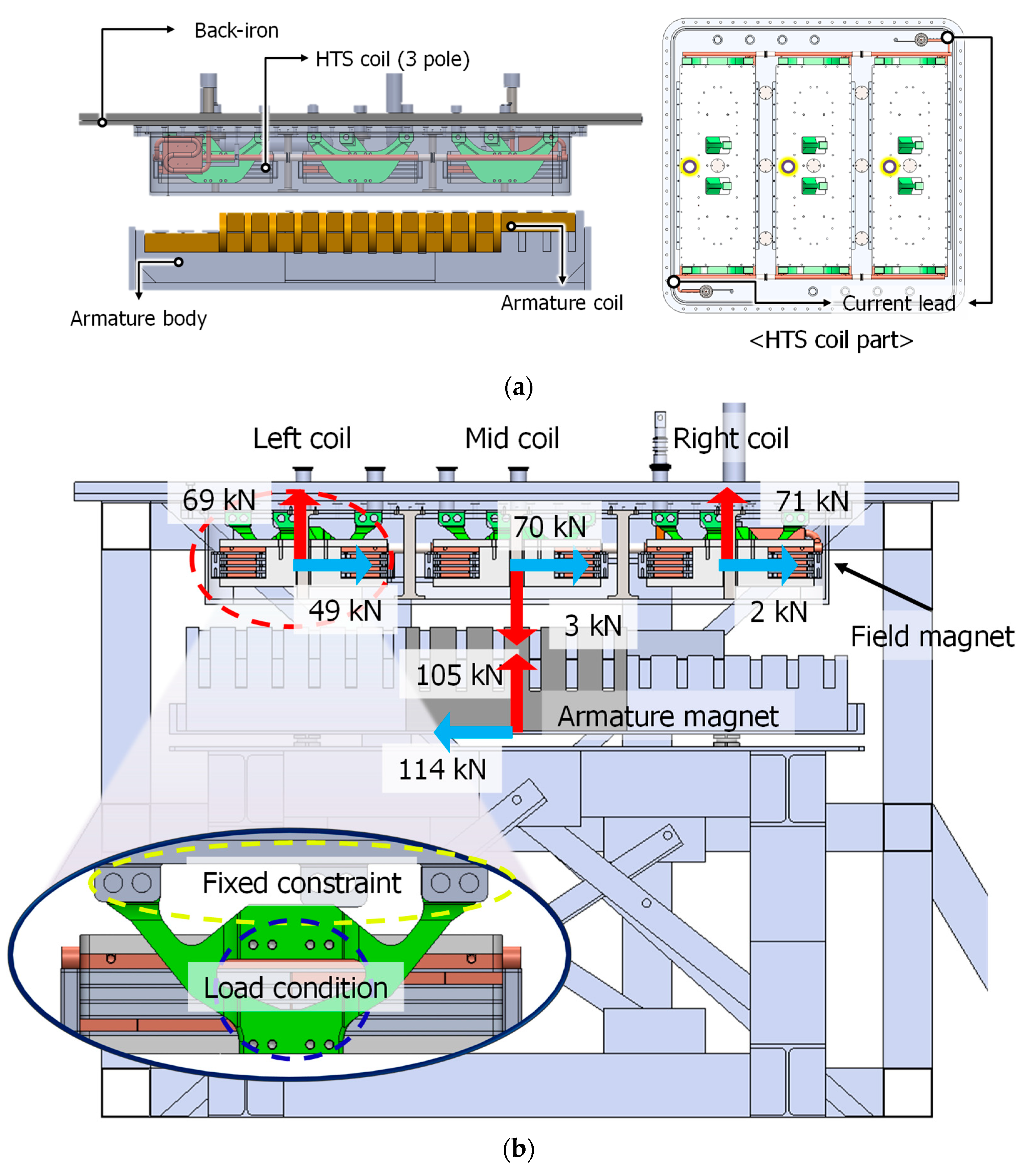
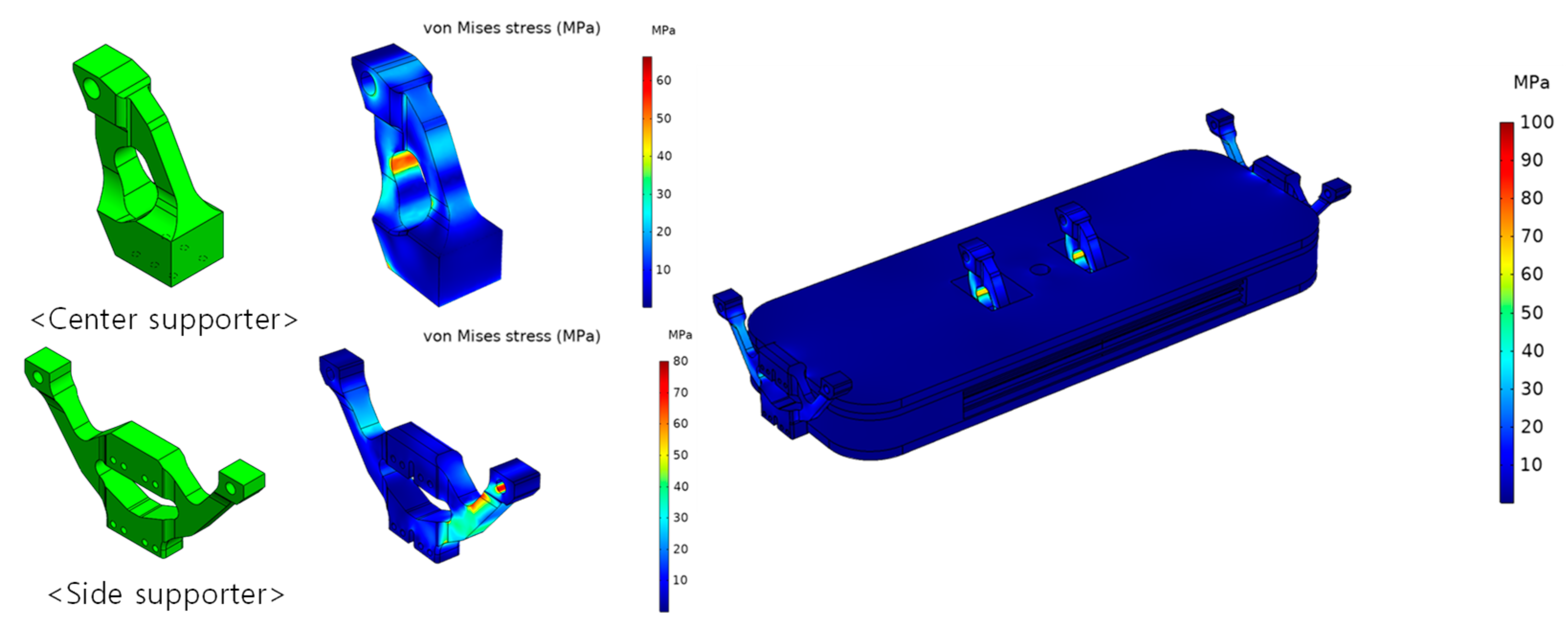
2.2. Design of the PES
3. Fabrication of the PES
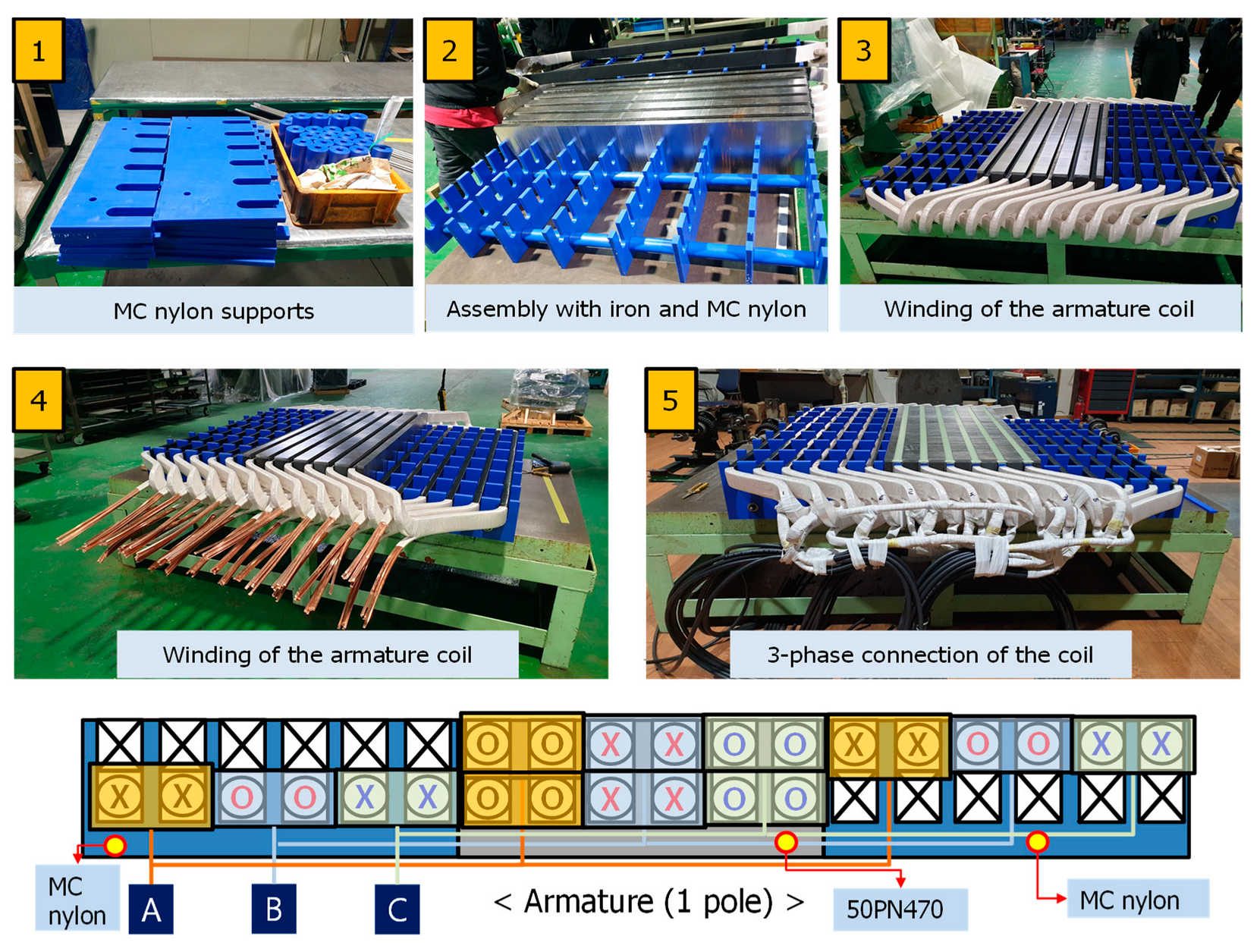
3.1. Fabrication of the HTS Field Coils and Armature Coil
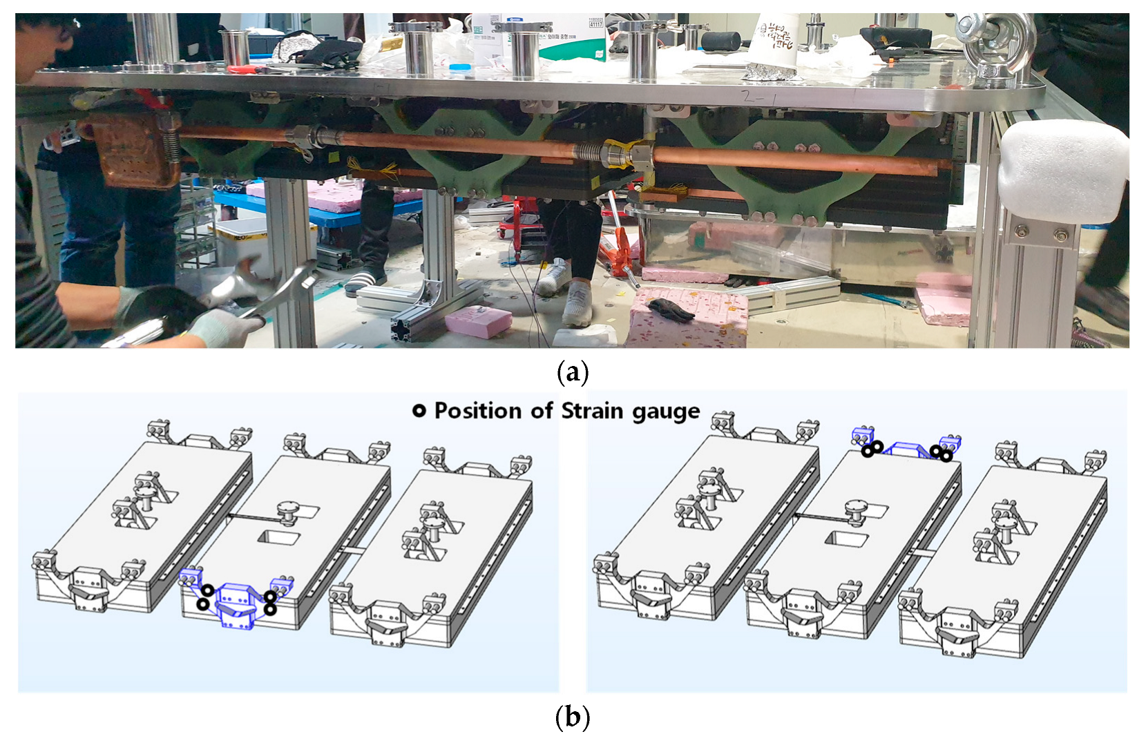
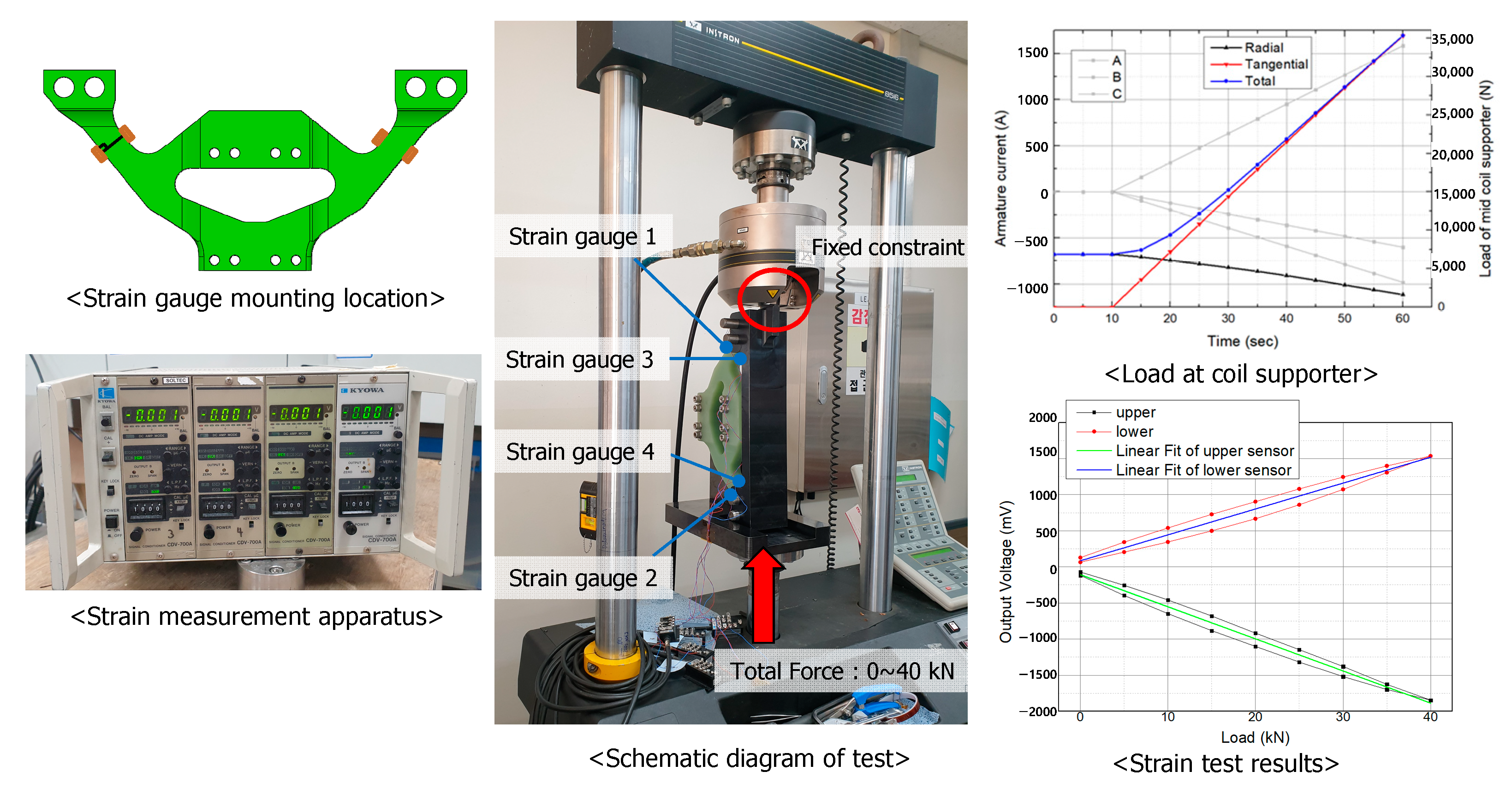
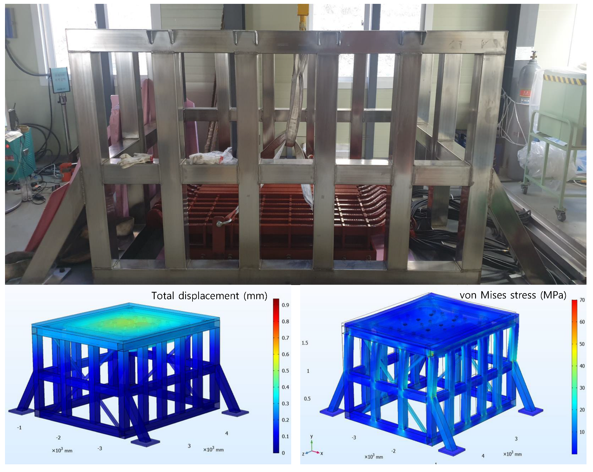
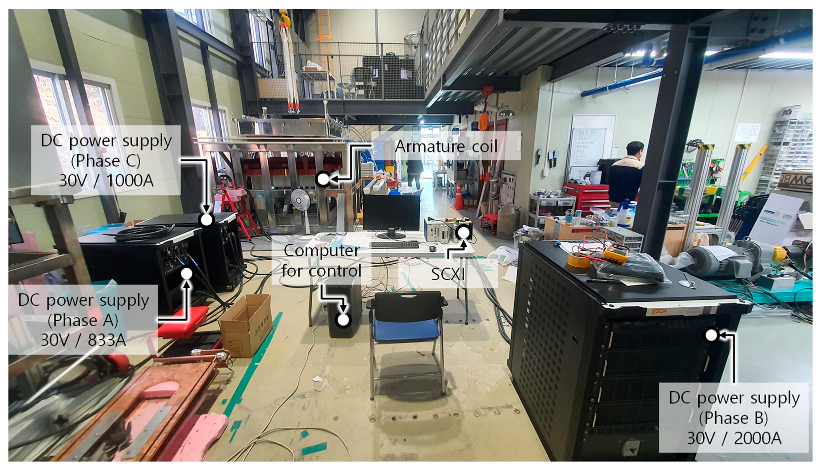
3.2. Experimental Setup of the PES for Testing the Electromagnetic Forces
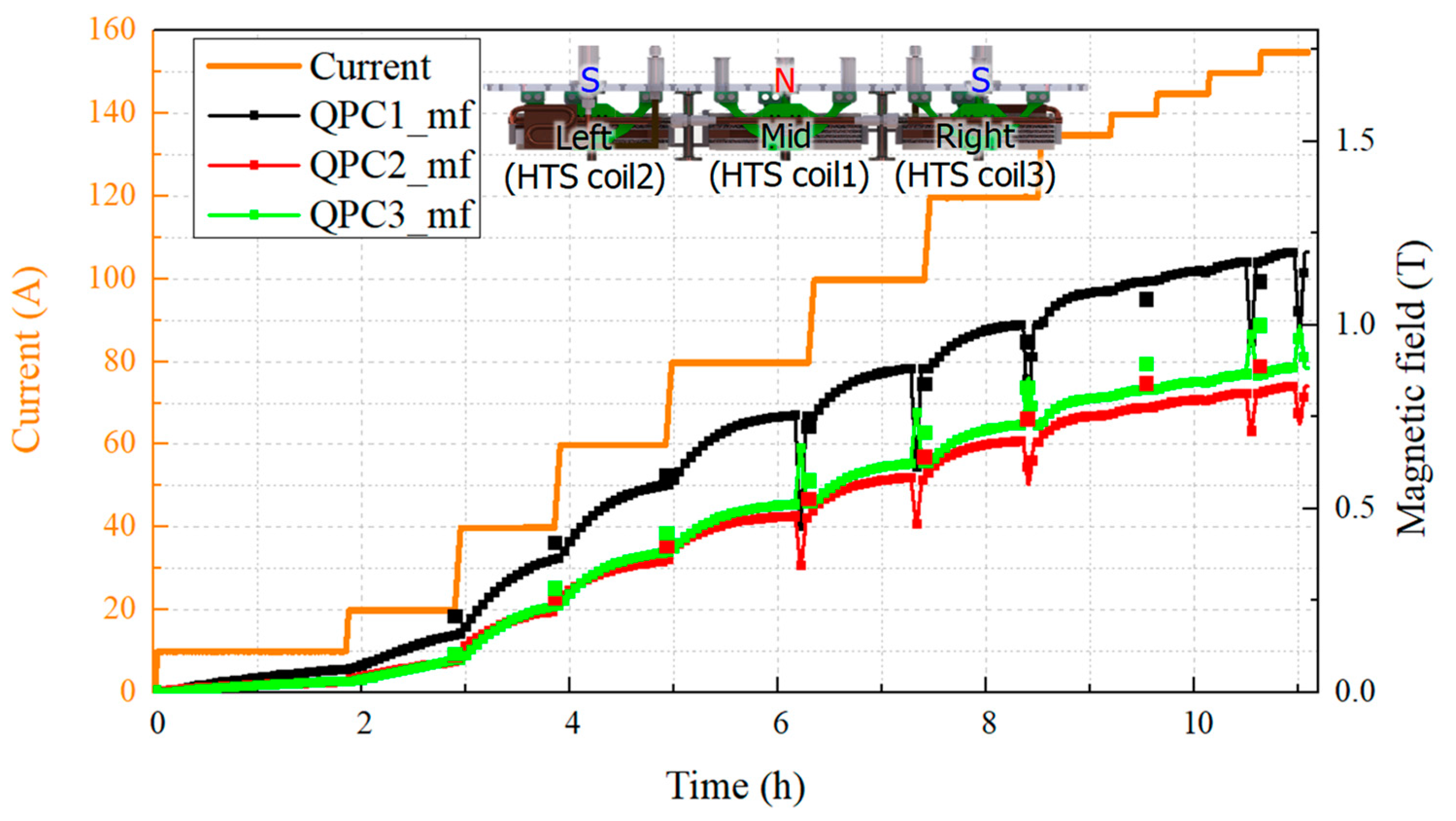
4. Experiment Results of HTS Coil Using the PES
5. Conclusions
Author Contributions
Funding
Data Availability Statement
Conflicts of Interest
References
- IRENA. Future of Wind: Deployment, Investment, Technology, Grid Integration and Socio-Economic Aspects (A Global Energy Transformation Paper); International Renewable Energy Agency: Masdar City, United Arab Emirates, 2019. [Google Scholar]
- Soares, R.; Oliveira, A.; Sarrias, M.; Fernandez, R. Current status and future trends of offshore wind power in Europe. Energy 2020, 202, 117787. [Google Scholar] [CrossRef]
- Goudarzi, N.; Zhu, W.D. A review on the development of wind turbine generators across the world. Int. J. Dyn. Control 2013, 1, 192–202. [Google Scholar] [CrossRef]
- Tumse, S.; Bilgili, M.; Yildirim, A.; Sahin, B. Comparative Analysis of Global Onshore and Offshore Wind Energy Characteristics and Potentials. Sustainability 2024, 16, 6614. [Google Scholar] [CrossRef]
- Barooni, M.; Ashuri, T.; Velioglu Sogut, D.; Wood, S.; Ghaderpour Taleghani, S. Floating Offshore Wind Turbines: Current Status and Future Prospects. Energies 2023, 16, 2. [Google Scholar] [CrossRef]
- Asim, T.; Islam, S.Z.; Hemmati, A.; Khalid, M.S.U. A Review of Recent Advancements in Offshore Wind Turbine Technology. Energies 2022, 15, 579. [Google Scholar] [CrossRef]
- Tyler, A.H.; Elizabeth, J.W.; Jeffrey, P.F.; Malte, J.; Philipp, B.; Bjarne, S.; Bolun, X.; Jérôme, G.; Marie, M.; Lena, K. Five grand challenges of offshore wind financing in the United States. Energy Res. Soc. Sci. 2024, 107, 103329. [Google Scholar]
- Sun, R.; Abeynayake, G.; Liang, J.; Wang, K. Reliability and Economic Evaluation of Offshore Wind Power DC Collection Systems. Energies 2021, 14, 2922. [Google Scholar] [CrossRef]
- Bensalah, A.; Barakat, G.; Amara, Y. Electrical Generators for Large Wind Turbine: Trends and Challenges. Energies 2022, 15, 6700. [Google Scholar] [CrossRef]
- Xu, Y.; Maki, N.; Izumi, M. Performance Comparison of 10-MW Wind Turbine Generators With HTS, Copper, and PM Excitation. IEEE Trans. Appl. Supercond. 2015, 25, 1–6. [Google Scholar]
- Brambilla, R.; Grilli, F.; Martini, L.; Bocchi, M.; Angeli, G. A finite element method framework for modeling rotating machines with superconducting windings. IEEE Trans. Appl. Supercond. 2018, 28, 5207511. [Google Scholar] [CrossRef]
- Haran, K.S.; Kalsi, S.; Arndt, T.; Karmaker, H.; Badcock, R.; Buckley, B.; Haugan, T.; Izumi, M.; Loder, D.; Bray, J.W.; et al. High power density superconducting machines—Development status and technology roadmap. Supercond. Sci. Technol. 2017, 30, 123002. [Google Scholar] [CrossRef]
- Song, X.; Mijatovic, N.; Bührer, C.; Kellers, J.; Wiezoreck, J.; Krause, J.; Pütz, H.; Hansen, J.; Rebsdorf, A.V. Experimental Validation of a Full-Size Pole Pair Set-Up of an MW-Class Direct Drive Superconducting Wind Turbine Generator. IEEE Trans. Energy Convers. 2020, 35, 1120–1128. [Google Scholar] [CrossRef]
- Song, X.; Bührer, C.; Brutsaert, P.; Ammar, A.; Krause, J.; Bergen, A.; Winkler, T.; Dhalle, M.; Hansen, J.; Rebsdorf, A.V.; et al. Ground Testing of the World’s First MW-Class Direct-Drive Superconducting Wind Turbine Generator. IEEE Trans. Energy Convers. 2020, 35, 757–764. [Google Scholar] [CrossRef]
- Lewis, C.; Muller, J. A direct drive wind turbine HTS generator. In Proceedings of the IEEE Power Engineering Society General Meeting, Tampa, FL, USA, 24–28 June 2007; pp. 1–8. [Google Scholar]
- Klaus, G.; Wilke, M.; Frauenhofer, J.; Nickm, W.; Neumüller, H.W. Design challenges and benefits of HTS synchronous machines. In Proceedings of the IEEE Power Engineering Society General Meeting, Tampa, FL, USA, 24–28 June 2007; pp. 1–8. [Google Scholar]
- Ohsaki, H.; Terao, Y.; Quddes, R.M.; Sekino, M. Electromagnetic characteristics of 10 MW class superconducting wind turbine generators. In Proceedings of the IEEE International Conference on Electrical Machines and Systems, Incheon, Republic of Korea, 10–13 October 2010; pp. 1303–1306. [Google Scholar]
- Winkler, T. The ecoswing project. IOP Conf. Ser. Mater. Sci. Eng. 2019, 502, 1–9. [Google Scholar] [CrossRef]
- Jaen-Sola, P.; Donald, A.S.M.; Oterkus, E. Design of Direct-Drive Wind Turbine Electrical Generator Structures using Topology Optimization Techniques. J. Phys. Conf. Ser. 2020, 1618, 052009. [Google Scholar] [CrossRef]
- Tartt, K.; Amiri, A.; McDonald, A.; Jaen-Sola, P. Structural Optimisation of Offshore Direct Drive Wind Turbine Generators Including Static and Dynamic Analyses. J. Phys. Conf. Ser. 2021, 2018, 012040. [Google Scholar] [CrossRef]
- Sola, P. Advanced Structural Modelling and Design of Wind Turbine electrical Generators. Ph.D. Thesis, Newcastle University, Newcastle upon Tyne, UK, 2017. [Google Scholar]
- McDonald, A.; Bhuiyan, N.A. On the Optimization of Generators for Offshore Direct Drive Wind Turbines. IEEE Trans. Energy Convers. 2017, 32, 348–358. [Google Scholar] [CrossRef]
- McDonald, A. Structural Analysis of Low Speed, High Torque Electrical Generators for Direct Drive Renewable Energy Converters. Ph.D. Dissertation, University of Edinburgh, Edinburgh, UK, 2008. [Google Scholar]
- Maki, N.; Takao, T.; Fuchino, S.; Hiwasa, H.; Hirakawa, M.; Okumura, K.; Asada, M.; Takahashi, R. Study of practical applications of HTS synchronous machines. IEEE Trans. Appl. Supercond. 2005, 15, 2166–2169. [Google Scholar] [CrossRef]
- Sung, H.J.; Go, B.S.; Park, M. A Performance Evaluation System of an HTS Pole for Large-Scale HTS Wind Power Generators. IEEE Trans. Appl. Supercond. 2019, 29, 5203905. [Google Scholar] [CrossRef]
- Go, B.S.; Sung, H.J.; Park, M.; Yu, I.K. Design and Comparative Analysis of Performance Evaluation Systems for a Large-Scale HTS Generator. IEEE Trans. Appl. Supercond. 2019, 29, 5204005. [Google Scholar] [CrossRef]
- Kim, C.; Sung, H.J.; Go, B.S.; Nam, G.D.; Kim, S.; Park, M. Design and Property Analysis of a Performance Evaluation System for HTS Wind Power Generators. IEEE Trans. Appl. Supercond. 2020, 30, 5202805. [Google Scholar] [CrossRef]


| Items | Value |
|---|---|
| Rated output power | 10.5 MW |
| Rotating speed | 9.6 rpm |
| Rated torque | 10.57 MN·m |
| Rated Line to Line voltage | 6.6 kV |
| Rated armature current | 918 A |
| Number of poles | 40 |
| Rated frequency | 3.2 Hz |
| Effective length | 700 mm |
| Air gap | 18 mm |
| Weight of generator | 124.8 ton |
| Items | Value |
|---|---|
| Operating temperature | 35 K |
| Number of turns per layer | 310 |
| Number of layers per coil | 4 |
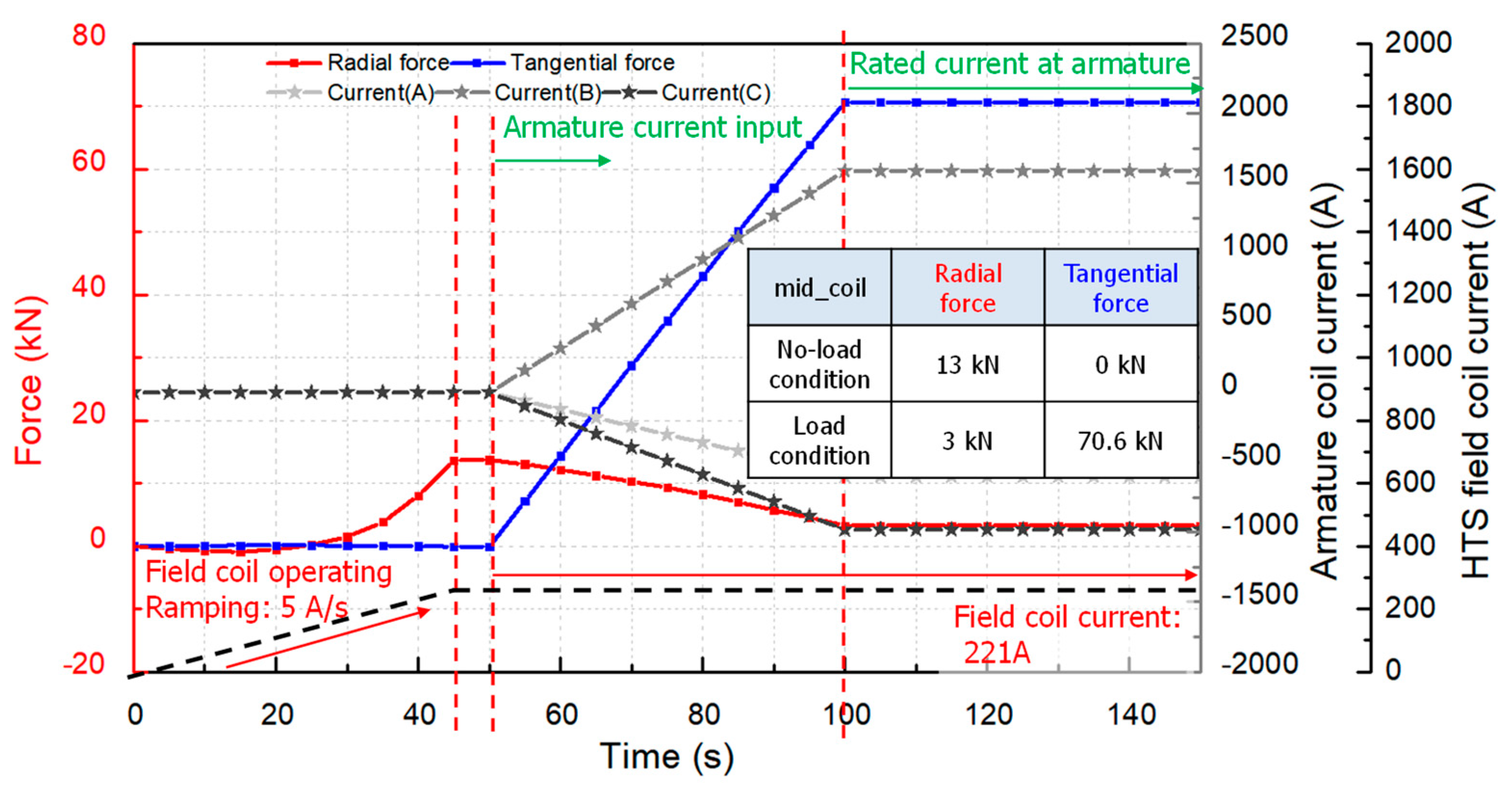
| Operating current | 221 A |
| Safety margin | 35% |
| Total length of the HTS wire (40 pole) | 115.64 km |
| Width of HTS field coil | 405 mm |
| Height of HTS field coil | 62 mm |
| Effective length of HTS field coil | 700 mm |
| Material of bobbins | Aluminum |
| Material of supports | GFRP |
| Material of salient pole | 50PN470 |
| Material of back iron | 50PN470 |
| Part | HTS Generator | PES | Error |
|---|---|---|---|
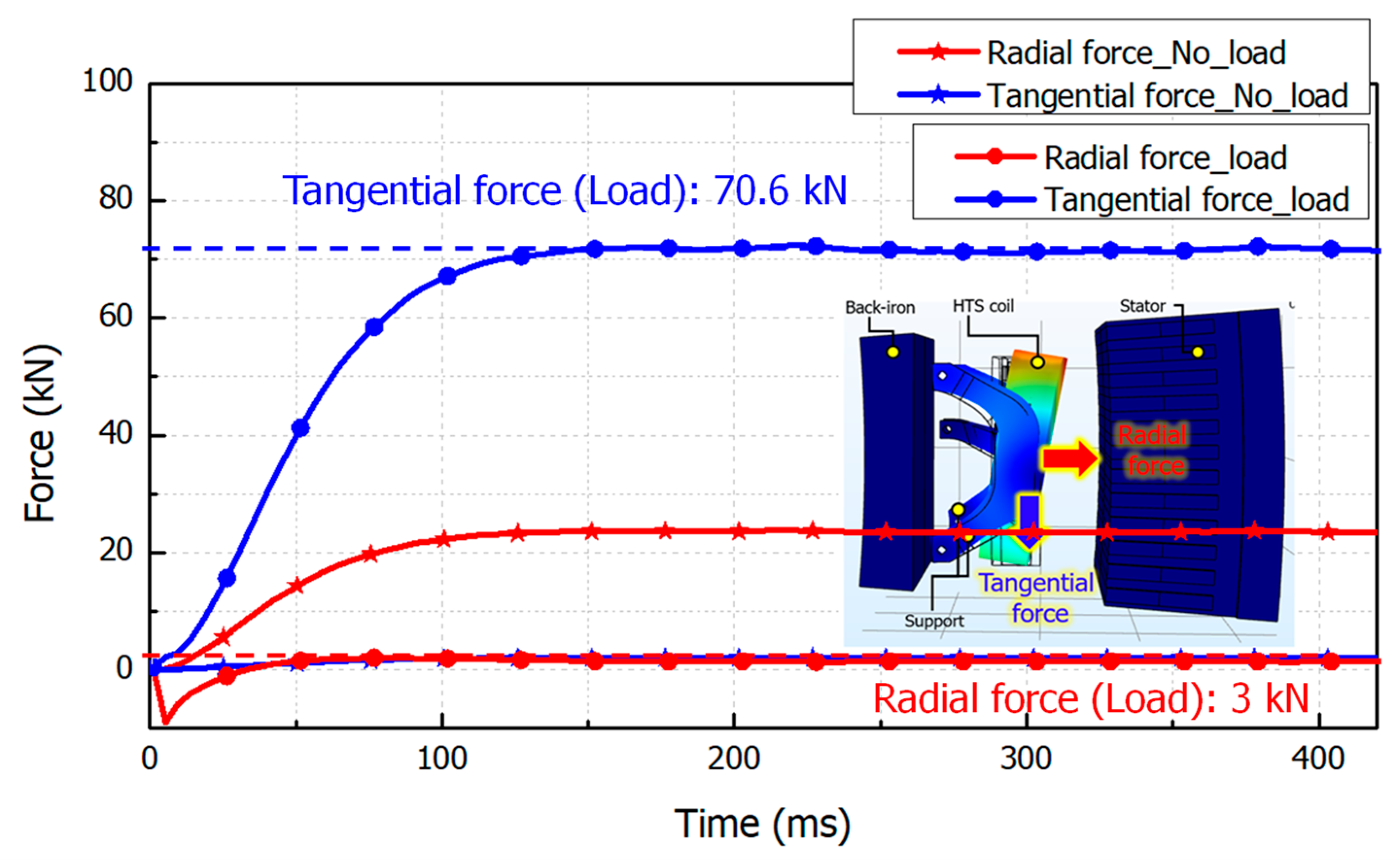
| Tangential force of the HTS field coil | 71.5 kN | 72.2 kN | 0.98% |
| Total output power | 10.5 MW | 10.6 MW | 0.98% |
Disclaimer/Publisher’s Note: The statements, opinions and data contained in all publications are solely those of the individual author(s) and contributor(s) and not of MDPI and/or the editor(s). MDPI and/or the editor(s) disclaim responsibility for any injury to people or property resulting from any ideas, methods, instructions or products referred to in the content. |
© 2024 by the author. Licensee MDPI, Basel, Switzerland. This article is an open access article distributed under the terms and conditions of the Creative Commons Attribution (CC BY) license (https://creativecommons.org/licenses/by/4.0/).
Share and Cite
Go, B.-S. Characteristic Analysis of Electromagnetic Force in an HTS Field Coil Using a Performance Evaluation System. Energies 2024, 17, 4366. https://doi.org/10.3390/en17174366
Go B-S. Characteristic Analysis of Electromagnetic Force in an HTS Field Coil Using a Performance Evaluation System. Energies. 2024; 17(17):4366. https://doi.org/10.3390/en17174366
Chicago/Turabian StyleGo, Byeong-Soo. 2024. "Characteristic Analysis of Electromagnetic Force in an HTS Field Coil Using a Performance Evaluation System" Energies 17, no. 17: 4366. https://doi.org/10.3390/en17174366
APA StyleGo, B.-S. (2024). Characteristic Analysis of Electromagnetic Force in an HTS Field Coil Using a Performance Evaluation System. Energies, 17(17), 4366. https://doi.org/10.3390/en17174366