Article

Thermal Performance Evaluation of a Single-Mouth Improved Cookstove: Theoretical Approach Compared with Experimental Data

by
Hamed Atajafari
1,
Birendra Raj Pathak
2 and
Ramchandra Bhandari
1,*
1
Institute for Technology and Resources Management in the Tropics and Subtropics, TH Köln (University of Applied Sciences), 50679 Cologne, Germany
2
School of Engineering, Royal Melbourne Institute of Technology (RMIT), Melbourne, VIC 3000, Australia
*
Author to whom correspondence should be addressed.
Energies 2024, 17(17), 4355; https://doi.org/10.3390/en17174355
Submission received: 13 June 2024 / Revised: 20 August 2024 / Accepted: 27 August 2024 / Published: 30 August 2024
(This article belongs to the Section J: Thermal Management)

Abstract

This work aims to address the knowledge gap in the thermal efficiency performance of a locally made cookstove in Mali. Despite the fact that the thermal efficiency of cookstoves is a crucial aspect of cooking, the performance of commercially produced cookstoves in Mali has not been thoroughly studied. In this context, the thermal efficiency of a single-mouth biomass stove has been investigated using a theoretical and experimental approach. First, the fundamental principles of physics for the three forms of heat transfer were applied. Then, the theoretical thermal efficiency of the stove was calculated based on the percentage share of energy gains and losses for the respective heat transfer modes. This analysis shows that the highest energy gain is achieved by radiation heat transfer from the flame and the fuel bed, followed by convection heat transfer to the bottom and sides of the pot, respectively. In order to validate the findings, the theoretical results have been compared with the experimental data at a case study site in Katibougou, Mali. Accordingly, the experimental thermal efficiency is slightly lower than the theoretical value, with a measured value of 27% compared to the theoretical value of 31.45%. The theoretical thermal efficiency can be closer to the experimental efficiency if the combustion losses caused by incomplete combustion of the fuel are taken into account.

1. Introduction

From the dawn of human history, biomass has been utilized for cooking and heating purposes. Currently, around 2.7 billion people use biomass to meet their daily energy needs [1]. The demand for firewood has led to global deforestation, soil degradation, and erosion. In addition, burning firewood emits dangerous chemicals and greenhouse gas emissions into the atmosphere, thereby adversely affecting both human health and the global climate. In 2021, biomass accounted for 10% of the world’s energy supply and 13% of energy consumption [2]. A large proportion of this is used by rural families in developing countries, who depend on biomass for 90% of their domestic energy needs. Most of these individuals use inefficient traditional cookstoves to prepare their meals, leading to high levels of local/indoor air pollution and increased firewood consumption. Therefore, the widespread use of efficient cookstoves can be a significant step to improve rural livelihood in these countries.
In the last four decades, numerous global organizations have made efforts to offer individuals improved and environmentally friendly cooking technologies. In addition, great progress has been made in improving cookstoves in recent decades [3,4,5,6]. Although there have been notable advancements in cookstove design, numerous households in developing countries continue to utilize inefficient cookstoves as they cannot afford the upgraded models or there is a lack of awareness of and technology for improved cookstoves (ICSs).
More than 94% of the urban Malian population rely on solid fuels for cooking, and only about 6% have access to clean energy sources. Indeed, less than 0.5% of the population use improved cookstoves, which combust firewood or charcoal with a higher efficiency [7]. Panels a–f in Figure 1 indicate some samples of traditional wood and charcoal cookstoves used by Malian households.
Hence, a successful approach for providing individuals with better cooking facilities is to identify potential enhancements and turn them into valued assets. To achieve this, heat transfer has been recognized as a research field that has the greatest potential to improve stove performance and allow more people to take advantage of improved cooking systems. The present work has been carried out in view of developing a theoretical model for understanding the basic physics underlying the three forms of heat transfer, i.e., conduction, convection, and radiation. The objective here is to examine each form of heat transfer separately and identify the theoretical thermal efficiency of a single-mouth improved cookstove, which is locally made in Mali. Once the efficiency is calculated and analyzed, the manufacturer could use the results to improve efficiency further by changing the geometry, materials, etc,, as well as the awareness in those villages, by comparing the low efficiency and health hazards of traditional open mouth stoves to the adoption of improved, higher efficiency (and thereby requiring less firewood) and less polluting (indoor health environment) cookstoves. To the authors’ knowledge, those locally built stoves in Katibougou have not yet been analyzed for their thermal performance. Therefore, this study aims to bridge the gap by investigating the thermal efficiency of a locally produced biomass stove using a combined theoretical and experimental approach.
In the past, several models have been reported for the performance analysis of cookstoves. Initial attempts at creating models for cookstoves date back to the 1980s at Eindhoven University when Prasad et al. introduced preliminary heat transfer models for both open and shielded fires in 1981 [8]. Following that, De Lepeleire et al. introduced basic design principles aimed at improving cookstove performances [9]. In their other work, De Lepeleire et al. made significant progress in the advancement of contemporary heat transfer modeling by introducing a mathematical model coupling convective heat transfer and a simple flue-gas flow [10]. In 1985, Prasad et al. derived the combustion chamber wall losses for three distinct materials—dried clay, ceramics, and metal—assuming one-dimensional transient heat conduction within a flat wall [11]. A theoretical framework carried out in 1988 by the Centre for Technology Alternatives for Rural Areas (CTARA) in India aimed to predict the efficiency and excess-air factors for various geometric and operational parameters of a wood-burning stove [12]. These studies provided an initial basis for developing better mathematical models later.
From the 1990s to the early 2000s, the researchers in this field concentrated on using CFD analysis. Although a CFD approach can have a high level of accuracy compared to a simple model, it requires higher computational and operational costs as well as a properly skilled operator, thereby restricting its application to only high-value engineering fields. Therefore, in the traditional cookstove sector, conducting a parametric variation study using CFD has not been a viable choice [13]. In 2011, Agenbroad et al. created a simplified steady-state model to estimate bulk flow rate, temperature, and excess air ratio based on the stove geometry and firepower. In their work, the steady-state prediction results showed a satisfactory level of agreement with temporally averaged validation data obtained from typical stove operation [14]. Later in 2015, Kshirsagar et al. [13] presented a computationally inexpensive mathematical tool for the performance prediction of ‘rocket’ stoves with an unshielded pot. This work explored a new operating parameter called the ‘inlet area ratio’ and investigated the impact of this parameter on cookstove performance. It was concluded that the newly introduced parameter has a significant impact on the performance of a natural draft stove. In 2019, Parajuli et al. [15] formulated a mathematical framework for a dual-pot mud biomass stove, considering transient heat transfer, combustion chemistry, and fluid flow. The model is able to modify the operating and design parameters. Recently, in 2022, Sadiki and their team examined how varying levels of firepower affect the flow dynamics in biomass natural convection-driven cooking stoves. They developed a basic analytical model for the rate of entropy generation in the flow field and validated the model with experiments [16]. Table 1 shows selected relevant literature that studied the type of stoves using different models.

2. Materials and Methods

The cookstove used in this work is illustrated in panel (f) of Figure 1. It is a single-mouth ICS produced by local manufacturers, which is equipped with a chimney, and the stove structure’s is made of fired clay, brick, cement, and metal. In addition, it is designed for burning firewood, branches, and briquettes. The important geometric parameters for the given stove configuration are listed in Table 2.
This work aims to develop a theoretical approach to analyze three modes of heat transfer for the given single-mouth cookstove. For this purpose, fundamental principles of physics were applied to all parts of the stove and pot. The key components of the study consist of heat transfer principles, first law of thermodynamics, surface boundary layer behavior, and impinging jet flow. In order to determine the corresponding heat transfer parameters, the stove geometry and the firepower specified by the stove manufacturer were used as input values. To derive the output parameters, the mass flow rate and flue gas temperature were initially calculated. This was accomplished by setting the flow parameters and adjusting them based on the theoretical value of loss coefficient [17]. The fuel bed, flame, and surface temperatures as well as the calculation of the steady-state flue gas temperatures for different parts of the stove were derived from the methodology described in [17,18].

2.1. Theoretical Framework and Assumptions

As can be seen from Equation (1), the total thermal efficiency of the stove (ηt) depends on both combustion (ηc) and heat transfer efficiency (ηh) [18].
ηt = ηc × ηh
The combustion efficiency measures how much chemical energy stored in fuel is converted into thermal energy. The studies show that heat transfer efficiency is the most influential parameter for improving stove performance compared to the combustion efficiency. Therefore, if the heat transfer efficiency increases, this can potentially have a positive effect on the overall heat efficiency of the stove [18,19]. In this study, the combustion aspects of the process were ignored for the sake of simplicity and we assumed that the entire chemical energy of the fuel is converted into thermal energy (ηc = 1).
Figure 2 shows a schematic view of the single-mouth ICS with a chimney, along with the corresponding heat transfer modes.
Equation (2) expresses the rate of energy transfer through mass flow into or out of a system [18].
R a t e   o f   e n e r g y   f l o w = m ˙ × θ
where m ˙   is the bulk mass flow rate of the fluid ( k g / s ) and θ is the total energy of the flowing fluid per unit of mass ( J / k g ). The overall energy of passing air/flue gas per unit of mass can be further broken down into its basic components as given in Equation (3).
θ = h + k e + p e
where h is enthalpy (J/kg); ke and pe are kinetic energy and potential energy (J/kg), respectively.
In this study, an isobaric steady-flow condition was assumed, in which the mass flow in the stove remains constant. Moreover, kinetic and potential energy in the entire control volume from the inlet to the outlet is constant. Furthermore, ideal gas behavior and no mechanical work was assumed. Equations (4)–(8) provide the basis for evaluating the energy balance of the stove according to these assumptions [18].
E ˙ i   = E ˙ o
Q ˙ i + W ˙ i + i m ˙ θ = Q ˙ o + W ˙ o + o m ˙ θ
Q ˙ i Q ˙ o = m ˙ ( θ o θ i )
Q ˙ i Q ˙ o = m ˙ ( h o h i )
Q ˙ i Q ˙ o = m ˙ C p , a v g     ( T o T i )
where subscripts i and o are the inlet and outlet variables, respectively; Q ˙ is the rate of heat energy transfer (J/s); W ˙   is the rate of work energy transfer (J/s); Cp,avg is the average constant pressure specific heat of air/flue gas (J/kg K); and T is the gas temperature (K).
Equation (8) shows the relationship between mass flow rate, temperature, and heat transfer inside and outside of the cookstove. The steady-state energy balance provides a key perspective for assessing each form of energy transfer. As can be seen in Figure 3, all heat transfer modes (conduction, convection, radiation) are divided into two distinct groups: losses and gains. The heat losses are connected to the heat transferred to the stove body or to the surroundings, whereas the heat gains are related to the heat that is transferred to the pot. The steady-state energy balance with the corresponding heat transfer forms will be explained in the following sections.

2.1.1. Conduction

Heat is transferred by conduction, from the bottom of the stove floor to the ground, from the body of the stove to the surroundings, and the thickness of the pot. It was assumed that the stove walls were perfectly insulated; thus, no conduction heat transfer to the surroundings and pot was taken into account. Thus, the sole heat conduction loss considered in the overall energy balance is the transfer of heat through the stove floor to the ground, as shown in Figure 2. The steady-state heat transfer rate is defined by Equation (9) [18].
Q conduct = K × A × Δ T   L
where Qconduct is the conduction heat transfer (kW); K is the thermal conductivity (W/m K); A is the object cross-sectional area (m2); ΔT is the temperature difference (K); and L is the object thickness (m).

2.1.2. Convection

The high temperature gasses interact across two surfaces: the inside surface of the cookstove through the upper and lower parts of the combustion chamber (heat losses) and the outside surface of the pot (heat gains). Equation (10) defines the relative convection contribution in the steady condition [18].
Qconv_total = Qconv_low + Qconv_up + Qconv_pot bottom + Qconv_sides
where subscripts “low” and “up” are the variables in lower and upper portion; Qconv_total is the total convection heat transfer (kW); Qconv_low is the convection from gasses to lower combustion chamber walls (kW); Qconv_up is the convection from gasses to upper chamber walls (kW); Qconv_pot bottom is the convection to the pot bottom (kW); and Qconv_sides is the convection to the pot sides (kW).
This study considered the lower and upper sections (Figure 3) as two separate cylindrical channels, each having fully developed internal flow patterns with a constant mass flow rate and gas temperature [18]. In order to estimate a rough convection coefficient, flow parameters were calculated for each section in the transition zone between laminar and turbulent. Equations (11) and (12) explain the convection heat transfer across the lower and upper cylindrical channels, respectively [18].
Q conv _ low = h low × A low × ( T gas T low )
Q conv _ up = h up × A up × ( T gas T up )
where h is the convection coefficient (W/m2K); A is the object cross-sectional area (m2); and T is the temperature of the object (K).
The total convection gain originates from two primary sources, specifically impingement of the combustion gasses on the bottom surface of the pot and the scraping of the corresponding gasses on the pot sides. In this study, both sources were analyzed independently. The convection coefficient was calculated to determine the heat transfer into the pot under the assumption of an isothermal, non-reacting, impinging jet flow, using the method as described in the literature [18]. The convection of gasses to the pot bottom and sides is expressed by Equations (13) and (14), respectively [18].
Q conv _ pot = h conv _ pot × A pot × ( T gas T pot )
Q conv _ sides = h conv _ sides × A sides × ( T gas T pot )
where hconv_pot and hconv_sides are convection coefficients at the pot bottom and pot sides (W/m2K), respectively; Apot is the pot bottom surface area (m2); Asides is the pot side surface area (m2); Tgas is the gas temperature (K); and Tpot is the pot temperature (K).

2.1.3. Radiation

The radiant heat from the fuel bed or the flames is transferred to the pot, the stove body, and the surrounding. Equation (15) represents the total radiation energy balance [18].
Qrad_total = Qrad_low_ab + Qrad_up_ab + Qrad_flame_ab + Qrad_pot_ab + Qrad_pot sides
where Qrad_total is the total radiation heat transfer (kW); Qrad_low_ab is the radiation from the flames/fuel bed to the lower combustion chamber (kW); Qrad_up_ab is the radiation from the flames to the upper combustion chamber (kW); Qrad_flame_ab is the radiation to the pot from the high flames (kW); Qrad_pot_ab is the radiation transfer to the pot from the fuel bed (kW); and Qrad_pot sides is the radiation lost by the outer pot surface to the ambient surroundings (kW).
The level of radiation emitted by loss or gain is highly dependent on the temperature difference between two elements, the emitting surface area, the emissivity of each element, and the view factor [18]. The emissivity values of combustion flames, the fuel, and the stove body surface were obtained from the literature [20,21,22,23]. In terms of radiative losses to the body of the stove, the upper and lower chambers were studied individually; both were assumed to be fully closed, infinitely long concentric cylinders, with the fuel/flame bed representing the inner chamber geometry, as describe in the literature [18].
In order to develop the assumption of infinitely long concentric cylinders, the dimensions of the stove body (rectangular wall enclosure) were first converted into a circular wall enclosure as expressed in Equation (16) [24,25]. This assumption is made in order to reduce the complexity of the geometry and to simplify the calculation, as the lateral surface can be described by a constant value of the radius [26]. Therefore, the inner and outer parts of the combustion chamber were considered as two concentric cylinders, as shown in Figure 3. The inner and outer parts are identified by the indices “a” and “b”, respectively.
R b = L W π
where Rb is radius of the outer wall (m); L and W are the length and width of the rectangular enclosure wall (m), respectively.
The steady-state radiation losses at the walls of the lower and upper combustion chamber is described by Equations (17) and (18), respectively [18]
Q radiation _ low _ ab = σ Stefan × A low _ a × ( T l o w _ a 4 _ T l o w _ b 4 )   1 ε low _ a + 1 ε low _ b ε low _ b × r low _ a r low _ b
Q radiation _ up _ ab = σ Stefan × A up _ a × ( T u p _ a 4 _ T u p _ b 4 ) 1 ε up _ a + 1 ε up _ b ε up _ b × r up _ a r up _ b
where σStefan is Stefan Boltzmann’s constant (W/m2 K4); A is the object’s cross-sectional area at the lower and upper portions (m2); T is the temperature of the object (K); εlow_a and εup_a are the average emissivity value between the flames and fuel bed surface in the lower and upper portions; εlow_b and εup_b are the emissivity of the clay in the lower and upper portions; and r is the radius of the object in the lower and upper portion (m).
Equation (19) specifies the total radiation heat transferred from the fuel bed to the bottom of the pot. It is assumed that there is no radiation from the flames, the pot is a black body, and the fuel bed’s reflectivity is negligible. Equation (20) defines the total radiation heat transfer supplied by the flame sheet to the pot bottom, assuming that the pot is a black body, and the reflectivity of the flames is negligible [18].
Q rad _ pot _ ab = A pot _ a × F ab × σ Stefan × ( ε fuel _ bed × T pot _ a 4 T pot _ b 4 )
Q rad _ flame _ ab = A flame _ a × F flame _ ab × σ Stefan × ( ε flame × T flame _ a 4 T pot _ b 4 )
where Apot_a is the effective emitting area on the pot (m2); εfuel_bed is the emissivity value of the metal fuel bed surface; Tpot_a is the average temperature of the emitting area (K); Tpot_b is the average temperature of the pot surface (K); Aflame_a is the effective emitting flame area (m2); εflame is the emissivity value of the diffusion flame; and Tflame_a is the average temperature of the flame (K). The relative areas of the respective surfaces and the distance between them have been modified using view factors, which result from Equations (21) and (22) [18].
S view   = 1 + 1 + r p r o L pot   2 r e f f L pot   2      
F a b = 1 2 × S view   S view   2 4 r p r o r e f f 2 1 2
where Sview is the variable simplification for the view factor calculation; reff is the radius of the effective emitting area (m); rpro is the radius of the projected emitted area on the pot (m); and Lpot is the separation distance between the two effective areas (m).

2.1.4. Chimney Effect

In addition to investigating the gas temperature and mass flow rate impacts on heat transfer, it is essential to understand how these variables are affected by the geometry of the gas path, which differs depending on the stove geometry and the interface between the stove and the pot. The height of the chimney is a key geometric parameter that specifies the vertical distance between the heat source and the hot flue gasses discharged into the surroundings.
The heat generated by the stove produces hot gasses that have a lower density than the surrounding air located outside of the stove mouth. Therefore, the pressure gradient is caused by the buoyancy effect, resulting from the density gradient, as described in Equation (23) [18].
Δ P induced = g h chim ( ρ ambient ρ hot ) = g h chim ρ ambient ( 1 T ambient T hot )
where ΔPinduced is the pressure difference (Pa); ρambient is the ambient density (kg/m3); ρhot is the density of hot gasses (kg/m3); g is the gravitational acceleration (m/s2); hchim is the chimney height (m); Tambient is the ambient temperature (K); and Thot is the temperature of the hot gasses (K).
The pressure gradient in Equation (23) can be expressed in the form of mass flow rate across the stove, which depends on the chimney height, chimney cross-sectional area, the loss coefficient, and the temperature of the combustion gasses and ambient surroundings [17]. This relationship is represented by Equation (24).
m ˙ = L C × A ( Δ P i n d u c e d R s   T h o t ) 2 g h c h i m ( T h o t T a m b i e n t T a m b i e n t )
where m ˙   is the mass flow rate (kg/s); LC is the loss coefficient that reflects efficiency losses related to the friction and viscous losses of the flow caused by stove geometry and the heat lost at the chimney walls; A is the flow area (m2); and Rs is the universal gas constant (J/K·mol).
Assuming that the exhaust gas behaves as an ideal gas, the following correlations were defined for the exhaust gas properties ranging from 300 to 1500 K at 1 atm [13,27].
μ = 0.0447 × 10 5 × T 0.7775
        k = 0.00031847 × T 0.7775
C p = 0.9362 + 0.0002 × T
ρ = 353 / T
v = m ˙ ρ × A
R e = ρ v d μ
Pr = 0.685 (Constant)
Nu = 0.565 + Pr0.5 Re0.5
h conv = N u × k d
where μ is the dynamic viscosity of the flue gas (kg/m s); T is the temperature of the exhaust gas (K); k is the thermal conductivity of the exhaust flue gas (W/m K); Cp is the specific heat of the flue gas (kJ/kg K); Re is the Reynolds number; ρ is the density of the exhaust gas (kg/m3); v is the flue gas velocity (m/s); m ˙   is the mass flow rate (kg/s); A is the flow area (m2); d is the diameter of the flow path (m); Pr is the Prandtl number; Nu is the Nusselt number; and hconv is the convection coefficient (W/m2 K). The Reynolds number for impingement flow is interpreted as follows [18]:
100 < Re < 103 laminar flow
103 < Re < 104 transition to turbulence
104 < Re turbulent flow
The input parameters required for calculating the flow gas parameters and energy balance of all heat transfer modes are summarized in Table 3.

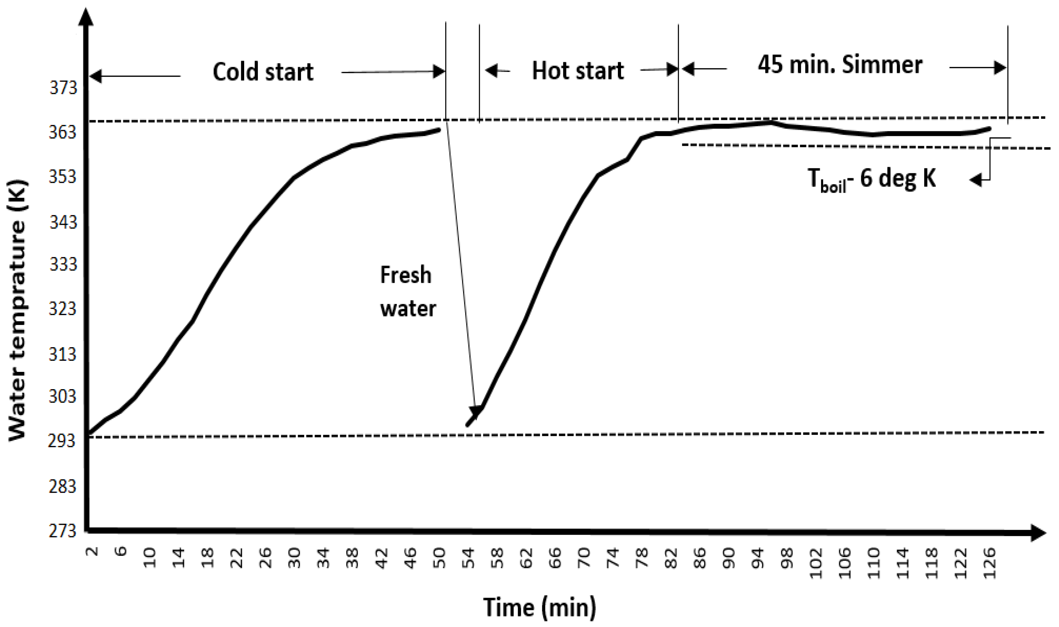
2.2. Experimental Validation

In this study, a water boiling test (WBT) was carried out to validate the theoretical thermal efficiency of the given cookstove. The water boiling test is a comprehensive assessment that evaluates the performance of a cooking stove by measuring several parameters including water mass loss, wood burned, and, optionally, pollutant data. The WBT uses these variables to calculate various performance metrics such as thermal efficiency (ηth), and is conducted in three different operational phases [28], which are as follows:
  • Phase 1: High power (cold start)
At the beginning of the WBT, two-thirds of the pot was filled with tap water as specified by the procedure, and the initial condition of the WBT was recorded as summarized in Table 4. In this regard, the equilibrium moisture content of the firewood was calculated, using the air relative humidity reported in March [29] and the recorded ambient temperature at the Katibougo site, Mali. According to the studies, the moisture content of firewood can vary significantly depending on the specific type of wood, climate, and storage conditions [30,31,32,33]. For the WBT, local Malian firewood (Pterocarpus erinaceus) that was stored outdoors and exposed to the direct sunlight was provided from a local market.
The water boiling test was started with a high-power cold start, in which the pre-weighed firewood was used to boil the water using the cookstove under study. The fuel was fed into the stove and ignited, and then the temperature of the water in the pot was measured with a thermometer at regular 2 min intervals until the water reached the boiling point (Figure 4). Afterwards, the following approaches were achieved:
(a)
The time at which the water inside the pot reached the local boiling point was recorded along with the temperature.
(b)
All fuel samples were carefully extracted from the cookstove and the flame was extinguished by gently blowing on the ends to remove loose ash, which was then collected and placed in a container for subsequent weighing and analysis.
The mass of unburnt firewood extracted from the cookstove was identified and recorded.
(c)
The weight of the pot containing hot water was measured and the weight recorded.
(d)
The ash collected from the stove was measured and the weight recorded.
  • Phase 2: High power (cold start)
The high-power hot start phase test was conducted directly following the high-power cold start phase to assess the performance of the stove in cold and warm conditions. The test methodology used for the high-power cold start phase was duplicated for the high-power hot start phase.
  • Phase 3: Low Power (Simmering)
The final test in the WBT was the simmering phase test. In this step, the quantity of fuel needed to heat a certain amount of water to just below boiling point was evaluated. The fire was regulated to keep the water temperature slightly below the local boiling point (max. 6 degrees) for 45 min. Table 5 shows the water boiling test parameters for the fixed ICS model. The corresponding operational parameters of the given fixed ICS were determined using water boiling test data [28].

3. Results and Discussion

In this work, the heat transfer characteristics of the single-mouth cookstove were analyzed theoretically and experimentally. First, a theoretical approach for three modes of heat transfer was applied as a tool to evaluate the overall thermal efficiency of the stove, and then the results were validated with experiments.
All heat transfer modes analyzed in this work are influenced by the flow characteristics of the combustion gasses through the stove geometry, as presented in Table 6. The parameters are determined by three dimensionless numbers, the Reynolds number (Re), Prandtl number (Pr), and Nusselt number (Nu), as well as properties that are dependent on the gas temperature. The Reynolds number is used to determine the flow behavior of the gas, whether it is laminar or turbulent, and to calculate the heat transfer coefficient in the combustion chamber and chimney. It requires knowledge of the gas velocity, gas density, length characteristics such as dimeter of the flow path, and dynamic viscosity of the flue gas. For this purpose, the average gas velocity required to calculate the Reynolds number was derived from the mass flow rate that is influenced by the pressure gradient generated by the chimney effect. The results show that the pressure difference due to the chimney effect is 14.39 Pa. To calculate the mass flow rate accurately, the friction and viscous losses of the flow caused by the stove geometry and heat lost at the chimney walls were calculated using the loss coefficient, as described in [18]. In addition, the pressure losses in the combustion chamber, chimney, and elbow at the chimney bottom were estimated separately, which can be considered for future design and operation optimization of the stove. The results indicate that the maximum pressure loss is caused by the elbow at the bottom of the chimney (0.75 Pa), followed by the pressure loss at the chimney (0.49 Pa) and the pressure loss at the channel (0.019 Pa).
The Prandtl number is another important dimensionless quantity that was used to calculate the Nusselt number and the subsequent convective heat transfer required to analyze the convective heat transfer mode. Afterwards, the contributions of the convective, conductive, and radiative heat transfer modes for the given cookstove were analyzed. Based on the theoretical results summarized in Table 7, the highest energy gain was derived by the radiation to the pot from the high flames (11.30%) and the radiation transfer to the pot from the fuel bed (7.76%) followed by convection to the pot bottom (7.06%) and convection to the pot sides (5.32%), respectively. Accordingly, the theoretical efficiency of the stove was calculated by adding the convection and radiation gains together, resulting in an overall efficiency of 31.45%.
The theoretical model developed in this study not only quantifies the thermal efficiency of the biomass cookstove but also illustrates how various heat transfer mechanisms contribute to energy dynamics and provides several key insights that advance the understanding of the thermal efficiency of single-mouth biomass stoves. Firstly, it highlights the significance of radiation heat transfer in terms of energy gain achieved from the flame and fuel bed to the pot. This finding suggests that optimizing the stove design to improve the radiation heat transfer could significantly improve the thermal efficiency. Secondly, the theoretical model indicates that convection heat transfer to the pot bottom and pot sides is also an important contributor to energy gain. This has implications for stove design, because it implies that optimizing the pot design and placement within the cookstove could further enhance the thermal efficiency. Moreover, using pots made from materials with higher thermal conductivity can better facilitate heat transfer, thereby improving the overall cooking performance. Finally, the theoretical model allows us to obtain insight into the energy losses, which is a crucial factor for improving the stove design.
As can be seen from Table 7, the major energy losses are caused by the radiation of the flames into the upper combustion chamber (23.77%), followed by the energy loss from the chimney (14.77%); the radiation of the flames/fuel bed into the lower combustion chamber (12.10%); and the radiation lost by the outer pot surface to the ambient environment (8.47%), which all contribute to a lower thermal efficiency. Therefore, minimizing such energy losses can potentially increase the thermal efficiency of the stove. The minimum radiation loss can be achieved by improving the stove surface, insulating around the stove and optimizing the position and size of the pot. For example, a smooth surface can be created by applying a ceramic coating or using a metal with a high reflectivity. Additionally, insulation around the cookstove can reduce heat loss by reducing the temperature difference between the cookstove and the surrounding environment. Furthermore, optimization of the position and size of the pot can minimize radiation losses by adjusting the surface area exposed to the environment. Energy loss through the chimney is also a significant contributor to the overall efficiency of cookstove. In this context, insulation and optimization of the chimney diameter will reduce heat losses considerably by optimizing the surface area exposed to the surrounding environment. By implementing these approaches, a higher overall efficiency can be gained for the given stove.
In order to validate the theoretical thermal efficiency, a water boiling test was carried out and the theoretical findings were compared with the experiments. As can be seen from Table 8, the stove achieves a thermal efficiency of 24% in the cold start phase and 30% in the hot start phase, corresponding to an overall efficiency of 27%. Therefore, the experimental thermal efficiency is slightly lower than the theoretical thermal efficiency. In addition, a comparison of the theoretical and experimental results with the literature shows that the results are in the range in which the studies indicate to be the typical heat transfer efficiency of stoves, which is frequently in the range of 10 to 40% [19].
Despite the water boiling test being a widely accepted standard for evaluating stove performance, it has limitations in reflecting real-world cooking practices because it is conducted in a laboratory based-setup with trained technicians that may not accurately reflect how stoves are used in everyday life. To obtain a more accurate view of stove performance, especially with local foods and local cooking practices, it is necessary to use the controlled cooking test (CCT) in conjunction with the water boiling test [28]. The CCT not only captures the variability of actual cooking scenarios but it also accounts for user behavior, which plays a significant role in the effective use of the stove. Additionally, combining both testing methods can provide a more comprehensive understanding of energy efficiency under realistic cooking conditions, ultimately leading to stove designs that are better suited for the specific needs and practices of users in Malian cultural contexts.
It is obvious that the theoretical thermal efficiency is slightly higher than the experimental one. The reason lies in the simplifications of the model, as the theoretical thermal efficiency of the stove is calculated based on the steady-state energy balance for each mode of heat transfer, and combustion losses due to incomplete combustion of the fuel are unaccounted in this work. Based on the studies, typical combustion efficiencies for cooking stoves and even sometimes three-stone fires can be more than 90% [19]. Therefore, the theoretical thermal efficiency of the stove compared to the experimental thermal efficiency can be modified by taking the combustion losses into account.
However, the assumption of 100% combustion efficiency could have the following implications for the findings and potential real-world applications. Firstly, this assumption may overestimate the actual performance of the stove, resulting in an inaccurate representation of the stove’s ability to convert fuel into usable heat. Secondly, the results may not be directly comparable to other studies that have taken combustion efficiency into account. In addition, it might lead to conclusions that are not representative of real-world scenarios, where combustion efficiency is typically lower. Additionally, assuming a combustion efficiency of 100% may lead to designs that are not optimized for real-world applications or may underestimate emissions from the stove in real operations, leading to inaccurate estimates of environmental impact.
In view of the above points, it is crucial to consider incorporating parameters related to combustion efficiency in future studies. Doing so would enhance the accuracy of the results, ensuring that the findings better reflect the complexities of real-world cooking practices and contribute positively to stove design improvements and environmental sustainability.
An increase in the efficiency of a biomass stove can bring potentially three major benefits to households: (1) a reduction in firewood consumption resulting in economic and time-related benefits and increasing the sustainable use of the natural resources; (2) a reduction in human exposure to harmful air pollutants; and (3) a reduction in greenhouse gas emissions, which are expected to increase the risk of global climate change [36]. In general, an efficient cookstove can save a family around 700 kg of firewood annually, while reducing CO2 emissions by 161 kg at the same time [37].

4. Conclusions

This study has focused on three modes of heat transfer as key parameters for determining the thermal efficiency of a single-mouth cookstove. In this context, a theoretical approach was used to identify the energy gains and losses of each heat transfer mode, and then the theoretical thermal efficiency of the stove was calculated based on the convection and radiation gains. In order to validate the theoretical thermal efficiency, a water boiling test was performed in the laboratory and the theoretical finding was compared with the experimental values. The main conclusions of the study are summarized below:
  • The maximum energy gain was achieved by radiation to the pot from the high flames and radiation transfer to the pot from the fuel bed followed by convection to the pot bottom and convection to the pot sides, respectively.
  • The thermal efficiency calculated on basis of the theoretical approach agrees closely with the experimental values.
  • By considering the combustion losses, the theoretical thermal efficiency of the stove can be modified compared to the experimental values.
Although the theoretical approach can estimate the heat transfer and thermal efficiency of the single-mouth cookstove, it is not able to assess the combustion-related factors for CO, CO2, and combustion efficiency. Thus, research into combustion parameters can further enhance the results of this study.
To achieve a more accurate assessment of stove performance, it is crucial to integrate the controlled cooking test (CCT) with the water boiling test, as this combination allows for a comprehensive evaluation of stove performance under conditions that reflect local food choices and cooking practices.

Author Contributions

Conceptualization, R.B.; methodology, H.A. and B.R.P.; software, H.A.; formal analysis, H.A.; investigation, H.A. and B.R.P.; resources, R.B.; data curation, H.A.; writing—original draft preparation, H.A., B.R.P. and R.B.; writing—review and editing, R.B., H.A. and B.R.P.; visualization, H.A.; project administration, R.B.; funding acquisition, R.B. All authors have read and agreed to the published version of the manuscript.

Funding

This research was funded by the German Federal Ministry of Education and Research (BMBF) through its Project Management Agency DLR (PtDLR) under the framework of the C-Cook-Mali project (grant number: 01DG21023).

Data Availability Statement

The experimental and model data can be made available upon request.

Acknowledgments

The authors would like to acknowledge the support from the staff members and students of the C-Cook-Mali project team at USTT-B and IPR-IFRA during the data collection process and field experiment in Katibougou, Mali.

Conflicts of Interest

The authors declare no conflicts of interest.

Abbreviations

Nomenclature Greek Symbols
Aobject cross-sectional area (m2)ΔTtemperature difference (K)
Achimneychimney cross-sectional area (m2)ΔPinducedpressure difference (Pa)
Afuel_bedfuel bed area (m2)εlow_aemissivity between flames and fuel bed in lower portion (-)
Aair_flowair flow area (m2)εlow_bemissivity of the clay in lower part (-)
CFDcomputational fluid dynamicsεflameemissivity value of diffusion flame (-)
Cp,avgaverage constant pressure specific heat of air/flue gas (J/kg K)εup_aemissivity between flames and fuel bed in upper portion (-)
dchimneychimney diameter (m)εup_bemissivity of the clay in upper part (-)
dlowdiameter of the combustion chamber in lower portion (m)ηccombustion efficiency (%)
dupdiameter of the combustion chamber in upper portion (m)ηhheat transfer efficiency (%)
eenergy terms (J)ηtoverall thermal efficiency (%)
Fabview factorθtotal energy of the flowing fluid per unit of mass (J/kg)
ggravitational acceleration (m/s2)μdynamic viscosity of flue gas (kg/m s)
hEnthalpy (J/kg) v kinematic viscosity of air/flue gas (m2/s)
hconvconvection coefficient (W/m2 K)ρambientambient density (kg/m3)
hchimneychimney height (m)ρotlower density (kg/m3)
hpot_gapheight of air gap between pot and drip pan (m) σ Stefan Stefan Boltzmann constant (W/m2 K4)
ICSimproved cookstove
kthermal conductivity (W/m K)
kekinetic energy (J/kg)
Lobject thickness (m)
LCloss coefficient (-)
L × H × Wlength × height × width (m)
Llowlength of combustion chamber in lower portion (m)
Luplength of combustion chamber in upper portion (m)
Lpotseparation distance between two effective areas (m)
m ˙ bulk mass flow rate of fluid (kg/s)
NuNusselt number (-)
Ppressure difference between inlet and outlet (Pa)
pepotential energy (J/kg)
pvflow energy of moving air/flue gas (J/kg)
PrPrantel number (-)
Q ˙ rate of heat energy transfer (J/s)
Qconductconduction heat transfer (kW)
Qconv_totaltotal convection heat transfer (kW)
Qconv_lowconvection from gasses to lower combustion chamber walls (kW)
Qconv_upconvection from gasses to upper chamber walls (kW)
Qconv_pot_ bottomconvection to the pot bottom (kW)
Qconv_sidesconvection to the pot sides (kW)
Qrad_totaltotal radiation heat transfer (kW)
Qrad_low_abradiation from flames/fuel bed to lower combustion chamber (kW)
Qrad_up_abradiation from flames to upper combustion chamber (kW)
Qrad_flame_abradiation to pot from high flames (kW)
Qrad_pot_abradiation transfer to pot from fuel bed (kW)
Qrad_ pot sidesradiation lost by outer pot surface to ambient (kW)
Qwastewasted heat out the chimney (kW)
Q ˙ infirepower (KW)
raradius of the inner wall (m)
rbradius of the outer wall (m)
reffradius of effective emitting area (m)
rproradius of projected emitted area on pot (m)
ReReynolds number (-)
Rsuniversal gas constant (J/K mol)
Tgas temperature(K)
Tambientambient temperature (K)
Thottemperature of combustion gasses (K)
tpotthickness of pot (m)
Tiinlet gas temperature(K)
Tooutlet gas temperature (K)
Sviewvariable simplification for determining view factor (-)
uinternal energy (J/kg)
νspecific volume of the fluid (m3/kg)
W ˙ rate of work energy transfer (J)
WBTwater boiling test

References

  1. Sutar, K.B.; Kohli, S.; Ravi, M.; Ray, A. Biomass cookstoves: A review of technical aspects. Renew. Sustain. Energy Rev. 2015, 41, 1128–1166. [Google Scholar] [CrossRef]
  2. Popp, J.; Kovács, S.; Oláh, J.; Divéki, Z.; Balázs, E. Bioeconomy: Biomass and biomass-based energy supply and demand. New Biotechnol. 2021, 60, 76–84. [Google Scholar] [CrossRef]
  3. Jetter, J.; Zhao, Y.; Smith, K.R.; Khan, B.; Yelverton, T.; DeCarlo, P.; Hays, M.D. Pollutant Emissions and Energy Efficiency under Controlled Conditions for Household Biomass Cookstoves and Implications for Metrics Useful in Setting International Test Standards. Environ. Sci. Technol. 2012, 46, 10827–10834. [Google Scholar] [CrossRef]
  4. Kshirsagar, M.P.; Kalamkar, V.R. A comprehensive review on biomass cookstoves and a systematic approach for modern cookstove design. Renew. Sustain. Energy Rev. 2014, 30, 580–603. [Google Scholar] [CrossRef]
  5. MacCarty, N.; Still, D.; Ogle, D. Fuel use and emissions performance of fifty cooking stoves in the laboratory and related benchmarks of performance. Energy Sustain. Dev. 2010, 14, 161–171. [Google Scholar] [CrossRef]
  6. PCIA. Test Results of Cook Stove Performance. 2010. Available online: https://pciaonline.org/files/Test-Results-Cookstove-Performance.pdf (accessed on 18 June 2024).
  7. Bonan, J.; Battiston, P.; Bleck, J.; LeMay-Boucher, P.; Pareglio, S.; Sarr, B.; Tavoni, M. Social interaction and technology adoption: Experimental evidence from improved cookstoves in Mali. World Dev. 2021, 144, 105467. [Google Scholar] [CrossRef]
  8. Prasad, K.K. Some Studies on Open Fires, Shielded Fires and Heavy Stoves; Eindhoven University of Technology: Eindhoven, The Netherlands, 1981; p. 161. [Google Scholar]
  9. De Lepeleire, G.; Prasad, K.K.; Verhaart, P.; Visser, P.A. A Woodstove Compendium; Technische Hogeschool Eindhoven: Eindhoven, The Netherlands, 1981; p. 379. [Google Scholar]
  10. De Lepeleire, G.; Christiaens, M. Heat transfer and cooking woodstove modelling. Proc. Indian Acad. Sci. Sect. C Eng. Sci. 1983, 6, 35–46. [Google Scholar] [CrossRef]
  11. Prasad, K.K.; Sangen, E.; Visser, P. Woodburning Cookstoves. In Advances in Heat Transfer; Hartnett, J.P., Irvine, T.F., Eds.; Elsevier: Amsterdam, The Netherlands, 1985; pp. 159–317. [Google Scholar]
  12. Date, A. Investigation of CTARA wood-burning stove. Part II. Analytical investigation. Sadhana 1988, 13, 295–317. [Google Scholar] [CrossRef]
  13. Kshirsagar, M.P.; Kalamkar, V.R. A mathematical tool for predicting thermal performance of natural draft biomass cookstoves and identification of a new operational parameter. Energy 2015, 93, 188–201. [Google Scholar] [CrossRef]
  14. Agenbroad, J.; DeFoort, M.; Kirkpatrick, A.; Kreutzer, C. A simplified model for understanding natural convection driven biomass cooking stoves—Part 1: Setup and baseline validation. Energy Sustain. Dev. 2011, 15, 160–168. [Google Scholar] [CrossRef]
  15. Parajuli, A.; Agrawal, S.; Tharu, J.K.; Kamat, A.K.; Jha, A.K.; Darlami, H.B. A simplified model for understanding the performance of two-pot enclosed mud cookstoves. Clean Energy 2019, 3, 288–306. [Google Scholar] [CrossRef]
  16. Augustin, L.M.; Vertomene, S.T.; Bernard, N.N.; Sadiki, A.; Haddy, M.K. A New Perspective on Cooking Stove Loss Coefficient Assessment by Means of the Second Law Analysis. Entropy 2022, 24, 1019. [Google Scholar] [CrossRef]
  17. Agenbroad, J.N. A Simplified Model for Understanding Natural Convection Driven Biomass Cooking Stoves. Master’s Thesis, Colorado State University, Fort Collins, CO, USA, 2010. [Google Scholar]
  18. Zube, D.J. Heat Transfer efficiency of biomass cookstoves. In Mechanical Engineering; Colorado State University: Fort Collins, CO, USA, 2010. [Google Scholar]
  19. Bryden, M. Design Principles for Wood Burning Cook Stoves; U.S. Environmental Protection Agency, Office of Air and Radiation: Washington, DC, USA, 2005.
  20. Evans, D.; Emmons, H. Combustion of wood charcoal. Fire Saf. J. 1977, 1, 57–66. [Google Scholar] [CrossRef]
  21. Felske, J.D.; Tien, C.L. Calculation of the Emissivity of Luminous Flames. Combust. Sci. Technol. 1973, 7, 25–31. [Google Scholar] [CrossRef]
  22. Larfeldt, J.; Leckner, B.; Melaaen, M.C. Modelling and measurements of heat transfer in charcoal from pyrolysis of large wood particles. Biomass-Bioenergy 2000, 18, 507–514. [Google Scholar] [CrossRef]
  23. ToolBox, T.E. Basics: Fluid Mechanics. 2009. Available online: https://www.engineeringtoolbox.com/fluid-mechanics-t_21.html (accessed on 13 February 2024).
  24. Socratic, Geometry, Perimeter and Area of Non-Standard Shapes. Available online: https://socratic.org/questions/how-can-you-convert-the-area-of-a-rectangle-into-the-area-of-a-circle (accessed on 14 July 2024).
  25. Incorpera, F.P. Fundamentals of Heat and Mass Transfer, 6th ed.; John Wiley & Sons, Inc.: New York, NY, USA, 2007. [Google Scholar]
  26. Cengel, Y.A. Heat and Mass Transfer: Fundamentals and Applications, 5th ed.; McGraw-Hill: New York, NY, USA, 2015. [Google Scholar]
  27. Holman, J.P. Heat Transfer, 10th ed.; McGraw-Hill: New York, NY, USA, 2010. [Google Scholar]
  28. PCIA. The Partnership for Clean Indoor Air. PCIA Bulletin. 2004. Available online: https://pciaonline.org/files/WBT4.1.2_0_0.pdf (accessed on 19 July 2024).
  29. Climate. Top, Relative Humidity in Bamako, Mali. Available online: https://www.climate.top/mali/bamako/humidity/ (accessed on 19 July 2024).
  30. Abbot, P.; Lowore, J.; Khofi, C.; Werren, M. Defining firewood quality: A comparison of quantitative and rapid appraisal techniques to evaluate firewood species from a southern African Savanna. Biomass Bioenergy 1997, 12, 429–437. [Google Scholar] [CrossRef]
  31. Jankowska, A. Assessment of sorptive properties of selected tropical wood species. Drv. Ind. 2018, 69, 35–42. [Google Scholar] [CrossRef]
  32. Glass, S.V.; Zelinka, S. Moisture Relations and Physical Properties of Wood; General Technical Report FPL–GTR–282; Forest Products Laboratory: Madison, WI, USA, 2010; pp. 4.1–4.19. [Google Scholar]
  33. Bertitault, D.; Rozis, J.F. Study of Local Cooking Habits and Adapted Water Boiling Test; Energy Environment Solidarity (GERES): Phnom Penh, Cambodia, 2014; Available online: https://www.geres.eu/wp-content/uploads/2019/10/study-of-local-cooking-habits-and-adapted-water-boiling-test_geres_aug2014.pdf (accessed on 21 May 2024).
  34. TimberAid, Wood Moisture Content Calculator. Available online: https://www.timberaid.com/calculator/fundamental/moisturecontent (accessed on 19 July 2024).
  35. The Gold Standard Foundation. Simplified Methodology for Clean and Efficient Cookstoves. 2022. Available online: https://globalgoals.goldstandard.org/408-ee-ics-simplified-methodology-for-efficient-cookstoves/ (accessed on 18 March 2024).
  36. Smith, K.R. Health, energy, and greenhouse-gas impacts of biomass combustion in household stoves. Energy Sustain. Dev. 1994, 1, 23–29. [Google Scholar] [CrossRef]
  37. Panwar, N.L.; Kurchania, A.K.; Rathore, N.S. Mitigation of greenhouse gases by adoption of improved biomass cookstoves. Mitig. Adapt. Strat. Glob. Chang. 2009, 14, 569–578. [Google Scholar] [CrossRef]
Figure 1. Various cookstoves used in Mali: (a) traditional three-stone stove; (b) traditional double mud stove; (c) portable metal stove; (d) improved charcoal stove; (e) single-pot stove made of clay; (f) single-mouth ICS with chimney.
Energies 17 04355 g001
Figure 2. Steady-state energy balance with the corresponding heat transfer modes.
Energies 17 04355 g002
Figure 3. Geometric equivalence of the rectangular wall, assuming infinitely long concentric cylinders. a and b represent cross-sectional view of inner and outer wall of cylindrical combustion chamber.
Energies 17 04355 g003
Figure 4. Temperature variation during the three phases of the WBT.
Energies 17 04355 g004
Table 1. Selected list of studies and their system configuration.
StudiesSystem ConfigurationHighlights of the Study
Prasad et al., 1981 [8]Open fires, shielded fires, and heavy stovesDevelopment of a preliminary heat transfer model.
De Lepeleire et al., 1981 [9]Various portable and fixed stovesPreparation of a technical panel for firewood and charcoal stoves.
De Lepeleire et al., 1983 [10]Wood-burning stoveDemonstrating a correlation between the stove geometry and its performance.
Prasad et al., 1985 [11]Shielded fireModeling of a transient heat transfer considering only heat conduction.
Date, 1988 [12]CTARA wood-burning stovePredicting the magnitudes of efficiency and excess air factors for different geometrical and operating parameters.
Agenbroad et al., 2011 [14]Insulated rocket elbow stoveDevelopment of a simplified model for predicting bulk flow rate, temperature, and air access ratio.
Kshirsagar et al., 2015 [13]Rocket stove with unshielded potDevelopment of a mathematical tool for the performance prediction of ‘rocket’ stoves.
Parajuli et al., 2019 [15]Two-pot enclosed mud cookstoveDevelopment of a mathematical model for a two-pot enclosed mud cookstove combined with transient heat transfer, combustion chemistry, and fluid flow.
Augustin et al., 2022 [16]Biomass cookstove driven by natural convection.Development of a simplified analytical model of the entropy generation rate within the flow field and model validation with experiments.
Table 2. Geometric parameters of single-mouth ICS with chimney.
ParameterValueSymbolUnit
Cookstove dimensions1120 × 750 × 710L × H × Wmm
Length of combustion chamber in lower portion230Llowmm
Length of combustion chamber in upper portion270Lupmm
Diameter of the combustion chamber in lower portion230dlowmm
Diameter of the combustion chamber in upper portion550dupmm
Chimney diameter100dchimneymm
Chimney height2250hchimneymm
Pot diameter550dpotmm
Thickness of pot4tpotmm
Height of air gap between pot and drip pan50hpot_gapmm
Fuel bed area196,250Afuel_bedmm2
Air flow area78,000Aair_flowmm2
Table 3. Input parameters for single-mouth ICS with chimney.
ParametersSymbolValueUnitRemark
Input parameters (operational)
FirepowerP25kWDetermined by manufacturer
Ambient temperatureTambient305K
Fuel bed temperatureTfuel _bed1127KEstimated based on [18]
Average temperature of the flame T flame 819KEstimated based on [18]
Average surface pot temperature T pot 325K
Input parameters (physical)
Effective radius of inner cylinder in lower portionrlow_a115mm
Effective radius of outer cylinder in lower portionrlow_b501mm
Length of channel in lower portionLlow230mm
Length of channel in upper portionLup270mm
Effective radius of inner cylinder in upper portionrup_a275mm
Effective radius of outer cylinder in upper portionrup_b501mm
Chimney diameterdchimney100mm
Chimney heighthchimney2250mm
Pot diameterdpot550mm
Pot height hpot350mm
Separation distance between two effective areasLpot280mm
Height of air gap between pot and drip panhpot_gap50mm
Fuel bed areaAfuel_bed196,250mm2
Thickness concrete floor L 50mm
Intermediate parameters (predicted)
Emissivity value of metal fuel bed surface ε fuel _ bed 0.83-
Emissivity value of diffusion flame ε flame 0.72-
Average emissivity value between flames and fuel bed surface in lower portion ε low _ a 0.797-
Emissivity of the clay in lower part ε low _ b 0.75-
Stefan Boltzmann constant σ Stefan 5.67 × 10⁻⁸W/m2K4
Average emissivity value between flames and fuel bed surface in upper portion ε up _ a 0.753-
Emissivity of the clay in upper part ε up _ b 0.75-
Thermal conductivity of concreteKconc0.8w/mK
Table 4. The initial condition of the WBT.
ParametersValueUnitRemarks
Ambient temperature305K
Air relative humidity18 %Reported in March [29]
Local boiling point363.04KTest location: Katibougou, Mali
Density of ambient air1.157kg/m3
Wind condition--No wind
Fuel dimensions300 × 50mm
Equilibrium moisture content of the wood3.95 %Calculated [34]
Dry weight of the pot9.93kg
Pre-weighed firewood13.64kg
Lower heating value of firewood (LHV)1.828 × 10⁷J/kg
Table 5. Water boiling test parameters.
ParametersCold Start PhaseHot Start PhaseSimmer Phase
StartFinishStartFinishStartFinish
Water temperature of the pot (K)295.75363.85297.25363.10363.25364.15
Weight of Pot with water (kg)47.6446.5045.9245.6045.6041.83
Weight of wood (kg)9.586.316.314.184.183.01
Table 6. Flow characteristics of the combustion gasses through the stove geometry.
Output Parameter
ParametersValueUnitRemark
Average flue gas temperature in lower channel1000Kcalculated based on [18]
Average flue gas temperature in upper channel942Kcalculated based on [18]
Density of flue gasses in lower portion of the channel0.353kg/m3
Flue gas temperature in chimney700Kcalculated based on [18]
Density of flue gasses in chimney0.504kg/m3
Overall mass flow rate through the stove8.83 × 10−3kg/sassuming LC = 0.5
Gas velocity of the flu in channel0.264m/s
Gas velocity of the flue in chimney2.23m/s
Gas viscosity in channel9.61 × 10−5kg/m⋅s
Gas viscosity in chimney7.28 × 10−5kg/m⋅s
Thermal conductivity of gas in channel0.068W/m⋅K
Reynolds number in lower channel flow233-
Nusselt number in channel13.19-
Convection coefficient for lower channel flow4.3W/m2K
Convection coefficient for upper channel flow1.832W/m2K
Convection coefficient for pot bottom11.98W/m2K
Reynolds number between pot and drip pan107-
Reynolds number in chimney1543-
Nusselt number in chimney33.07-
Pressure difference due to chimney effect14.39Pa
Head loss in channel1.12 × 10−3mcalculated based on [18]
Head loss in chimney0.101mcalculated based on [18]
Pressure loss in channel0.019Pacalculated based on [18]
Pressure loss in chimney0.49Pacalculated based on [18]
Pressure loss at the elbow (chimney bottom)0.75Pacalculated based on [18]
Resistance coefficient for 90-degree bend, K90 = 0.3
Total pressure drop through the stove1.259Pa
Table 7. Energy balance of the entire stove for all terms of heat transfer contributions.
ParametersSymbolValue (Kw)Relative Energy Contribution (%)
Energy gain
Radiation transfer to pot from fuel bedQrad_pot_ab1.9227.759
Radiation to pot from high flamesQrad_flame_ab2.80111.307
Convection to the pot bottom Q conv _ pot 1.7517.069
Convection to the pot sides Q conv _ sides 1.3175.316
Total heat transfer to the pot (thermal efficiency) 7.79131.451
Energy loss
Radiation from flames/fuel bed to lower combustion chamberQrad_low_ab2.99512.10
Radiation from flames to upper combustion chamberQrad_up_ab5.88923.774
Radiation lost by outer pot surface to ambientQrad_ sides2.1008.477
Conduction heat transfer through the concrete floor Q conduct 1.2905.207
Convection from gasses to lower combustion chamber walls Q conv _ low 0.9463.819
Convection from gasses to upper chamber walls Q conv _ up 0.0990.399
Wasted heat out the chimney Q waste 3.6614.773
Total energy accounted 24.77100.00
Table 8. Derived parameters from WBT and data calculation sheet.
ParametersCold Start PhaseHot Start PhaseSimmer PhaseUnitRemarks
Wood consumed3.272.131.17kg
Water vaporized from pot1.140.323.77kg
Time to boil50.0026.0046.00minSimmer test should be ~45 min
Thermal efficiency24.00 30 42.00 %** Overall thermal efficiency is 27%
Burning rate0.062 0.078 0.025 kg/min
Firepower19.16 23.80 7.62 kW
** The overall thermal efficiency of the stove corresponds to the average efficiency of the cold start high-power phase and hot start high-power phase only (i.e., not including the simmer phase) [35].
Disclaimer/Publisher’s Note: The statements, opinions and data contained in all publications are solely those of the individual author(s) and contributor(s) and not of MDPI and/or the editor(s). MDPI and/or the editor(s) disclaim responsibility for any injury to people or property resulting from any ideas, methods, instructions or products referred to in the content.

