Article

A Distributed Coordination Approach for Enhancing Protection System Adaptability in Active Distribution Networks

by
Manuel Acevedo-Iles
,
David Romero-Quete
and
Camilo A. Cortes
*
Department of Electrical and Electronic Engineering, Universidad Nacional de Colombia, Bogotá 111321, Colombia
*
Author to whom correspondence should be addressed.
Energies 2024, 17(17), 4338; https://doi.org/10.3390/en17174338
Submission received: 4 July 2024 / Revised: 15 August 2024 / Accepted: 27 August 2024 / Published: 30 August 2024
(This article belongs to the Special Issue Energy, Electrical and Power Engineering 2024)

Abstract

:
The electrical protection of active distribution networks is crucial for ensuring reliable, safe, and flexible operations. However, protecting these networks presents several challenges due to the emergence of bi-directional power flows, network reconfiguration capabilities, and changes in fault current levels resulting from the integration of inverter-based resources. This paper introduces an innovative protection strategy for active distribution networks, leveraging the principles of distributed coordination and multi-agent systems. The proposed strategy consists of two stages. The first stage involves a fault detection algorithm that relies solely on local measurements, while the second stage uses agent classification to compute the optimal operating time based on a dynamic matrix representation of the fault path, combined with a simplified distributed optimization problem. The coordination process is formulated as a set of linear optimization problems, simplifying the solution. The proposed protection strategy is validated in a real-time simulation environment using a modified CIGRE MV European grid as a case study, considering low-impedance symmetric fault scenarios and topological changes. The results demonstrate that the protection scheme exhibits robust performance, enhancing the adaptability of the protection equipment while ensuring suitable sensitivity and operational speed.

1. Introduction

In recent years, the integration of renewable energy resources has posed significant challenges to the electrical protection of active distribution networks (ADNs). As noted in [1,2,3], these challenges include bi-directional power flow, network reconfiguration capabilities, and fault current levels approaching nominal values. In response to these demands, studies such as [2,4] have advocated for adaptive protection systems, which provide dynamic responses suited to highly reconfigurable systems with fluctuating current levels. As described in [5], adaptive protection schemes dynamically adjust protection equipment parameters in real time, thereby maintaining the protection system’s sensitivity.
To achieve adaptive behavior, the literature commonly presents two strategies: com-munication-less and communication-based adaptive protection schemes. Communication-less schemes use algorithms that rely exclusively on local measurements to update protective equipment settings [6,7,8,9,10]. One notable method in this category is data-based protection systems. As shown by [6], machine learning algorithms can create a reliable dynamic protection system without requiring a well-defined fault behavior model. Research in [8,9,10] introduces offline schemes that use clustering and classification techniques to determine optimal setting adjustments, creating data-trained models for each protection device. These models, relying solely on local measurements, can identify the appropriate setting group. According to [9], these methods offer advantages such as simplicity, cost-effectiveness, and high dependability rates (ranging from 96% to 99%) in active distribution systems. However, their effectiveness depends on comprehensive, reliable databases, as noted in [7,8,9].
Currently, these databases are primarily derived from complex simulation models of distribution systems with high inverter-based resource (IBR) penetration. With the rapid increase in connected IBRs, these models require frequent retraining to maintain optimal performance, necessitating multiple recalibrations and a wide range of setting groups (SGs) to address every potential system scenario [11,12].
Conversely, communication-based approaches achieve dynamic protection through real-time communication links between protection devices and advanced logical functions [11,13,14,15,16]. As outlined in [13], these approaches utilize hierarchical structures and multi-agent-based systems (MASs) to adjust and make decisions about protection equipment based on active monitoring of the ADN. For instance, Refs. [14,15,16] employ a central protection and control unit to update protection equipment settings online, based on the real-time status of all protection devices. Another method, proposed in [17,18], involves a decentralized protection system where multiple central protection units oversee specific zones and coordinate with units in adjacent zones. Additionally, Ref. [11] describes a distributed protection system structure, where each protection device defines optimal operating times through direct information sharing with adjacent equipment.
In essence, communication-based methods enhance the selectivity, sensitivity, dependability, and speed of protection systems in ADNs. They allow for rapid and accurate assessment of the system’s topology, operation, and fault inception, facilitating responses based on pre-established logic. However, deploying these schemes requires sophisticated protection systems, complex coordination, communication capabilities, and cybersecurity measures [19]. Nevertheless, as discussed in [11], and, considering applications in other power system areas such as economic dispatch [20,21], adopting a distributed-structure approach simplifies and enhances the efficiency and robustness of multi-agent systems (MASs). This approach improves speed, efficiency, and resistance to cyber-attacks and single-point failures.
Building on the features of MASs and distributed system structures, this paper aims to enhance these characteristics through a distributed coordination problem statement, a dynamic matrix representation of the desired order of operations, and agent-based algorithms. This work extends our previous research presented at the IEEE PowerTech2023 Conference [22], which proposed a communication-based protection algorithm characterized by minimal communication reliance and streamlined logic for protection functions. This approach addresses fault detection and direction estimation, validated through a real-time simulation environment that accounts for the primary fault characteristics of IBRs, including small fault current contributions and mandatory voltage support capabilities under symmetrical three-phase fault conditions.
The main contributions of this paper are as follows:
  • Proposal of an adaptive communication-based protection scheme that leverages distributed coordination and under-voltage criteria. This scheme enhances the effectiveness of protection systems in active distribution networks.
  • Despite its communication dependence, the proposed scheme only requires a one-byte data exchange of element information between neighboring agents to ensure coordinated operation. This significantly reduces bandwidth requirements.
  • The scheme empowers non-adaptive protection equipment to exhibit adaptive characteristics. This is verified through real-time testing in a Controller Hardware-In-the-Loop (CHIL) experimental setup, considering the primary fault behavior of inverter-based resources (IBRs).
The subsequent sections of this paper are structured as follows: Section 2 elaborates on the essential concepts related to the fault behavior of inverter-based resources (IBRs), presenting the model utilized in this study for IBR impact analysis. It also provides a summary of the fundamental technical aspects concerning protection functions and algorithms. Section 3 introduces the proposed protection algorithm based on distributed protection coordination. Section 4 outlines the details of the proposed real-time simulation test bed. Section 5 assesses and discusses the algorithm’s performance across various symmetrical three-phase fault and network reconfiguration scenarios.

2. Background

This section outlines the essential characteristics of IBRs, also known as inverter-interfaced distributed generators (IIDGs) [23,24,25]. These characteristics are based on the ongoing transformation of active distribution networks. Additionally, the section introduces the general protection concepts that form the basis for the proposed protection scheme detailed in this paper.

2.1. Fault Behavior and Modeling of Inverter-Based Resources

The behavior of ADNs during fault scenarios is predominantly influenced by two characteristics of IBR fault responses:
  • Voltage support during fault events: IBRs are expected to remain connected to support voltage during fault events. For instance, in certain countries, inverters must adhere to the ride-through curves defined in IEEE 1547-2018 [26].
  • Dynamic limitation of fault current: to ensure the safety of inverters due to their reduced thermal capabilities, a dynamic limitation of fault current is employed [27].
Considering the voltage support capabilities that govern and define the fault behavior of IBRs, standards specify the minimum support time based on the nominal power of the generation units. However, due to their high controllability and four-quadrant power injection capability, there are now various options for power injection relations (more active or more reactive power) available [27]. This lack of standardization, coupled with current methods used for fault location and direction estimation, presents challenges in identifying and classifying fault events [28].
Presently, the industry offers a wide array of inverter technologies and control strategies. Nonetheless, as detailed in [27], the limitation algorithms, which are key elements governing IBR fault behavior, fall into two categories: current-controlled limitation algorithms and voltage-controlled limitation algorithms. The former operates with the inverter as a current source using a predefined current reference, limiting the current and supporting voltage drops or rises. This approach is commonly employed in practice.
Despite the variability in power injection under fault events [29,30], we analyze and present a model of IBR fault behavior with a current-controlled limitation algorithm. This model seeks to emulate the primary features of the limitation algorithm based on the control of active and reactive power injection as defined as follows:
Q r = Q r i f v s . 0.9 k I l i m i f v s . 0.5 ( a · v s . + b ) · I l i m i f 0.5 < v s . < 0.9
P r = P r i f v s . 0.9 I l i m 2 Q r 2 i f v s . < 0.9
In Equations (1) and (2), P r and Q r represent the active and reactive power setpoints, I l i m denotes the allowable fault current of the inverter, a and b define parameters of a slope that determine the amount of injection for medium-severity faults, and k is a factor that defines the maximal priority of reactive injection in critical voltage drops. In some IBRs, a k factor close to 1 is typically defined, representing the injection of reactive power in several fault events.
Based on the limited or modified power setpoints and using a synchronous reference frame, the current reference that defines the inverter’s behavior can be calculated. Typically, this current represents the positive sequence active (direct) and reactive (quadrature) setpoints. However, [31] proposes a comprehensive and complex current-reference generator model, enabling control over both positive and negative current injection by IBRs.

2.2. Fault Direction Estimation Algorithms

Current technologies for in-fault direction estimation utilize two approaches: memory-based protection algorithms and self-polarized algorithms.
The first algorithm uses the pre-fault voltage angle as a reference to determine current-flow direction. In grids dominated by synchronous generators, where voltage changes are minimal during faults due to the inertia of these generators, this approach provides accurate current-flow direction estimation. However, scenarios with high IIDG penetration, as noted in [32], pose challenges to memory-based algorithms due to the fast voltage response and variable equivalent source impedance of IBRs.
On the other hand, the second approach computes fault direction using the angle between the measured in-fault current and voltage. Accurate voltage measurement is crucial for this method, as it relies on the measured voltage angle during the fault event. Obtaining accurate voltage measurements can be challenging, particularly in cases of faults near the measurement points. Nevertheless, the dynamic behavior of self-polarized algorithms, as presented in [32], combined with well-defined power injection characteristics during fault events of IBRs, as described in [33], could enhance the performance of directional elements in active distribution grids. For instance, the study in [34] utilizes the differential phase angle of superimposed complex power to address the dynamic behavior of active distribution systems.

2.3. Graph Theory

One of the key aspects of the distributed optimization problem formulation is the use of a matricial representation for the information sharing in a network, typically using a graph representation [21,35]. When the direction of information sharing is relevant, a directed graph ( D ) can be built, representing the agents’ influence in a common neighborhood ( N ).
In this study, the directed graphs are represented using the Laplacian Matrix ( L ), satisfying Equation (3):
L ( D ) = D Y
where D is the degree matrix representing the link number or connectivity of each node and Y is the adjacency matrix showing the relationship between nodes.
The graph theory discussed here introduces only a few key concepts within the broader field. For a more comprehensive review, the works presented in [35,36] are recommended for further reading.

2.4. Optimal Protection Coordination

As presented in [37], protection coordination aims to define the operating times of each protection equipment, ensuring a proper staggered operation order. When striving for optimal protection coordination, as discussed in [12,38], the ensuing minimization problem can be stated as follows:
min f k = f = 1 N f ( i , j ) P ( t i , f k + t j , f k ) , k = 1 , , N G
s . t t j , f k t i , f k C T I ,
where f k represents the total operating time of the protection system for each one of the setting groups k available in the setting set N G ; P is a set describing the relation between the couples of operating times of primary i and backup j equipment evaluated across all fault scenarios N f . In order to ensure a staggered operation, a coordination time interval C T I is introduced within the restriction set, defining the minimum time difference between the operating time of the backup protection equipment t j , f k and the primary protection equipment t i , f k .
As discussed in [39], the operating time function is typically defined by an inverse-time curve, as presented in Equation (6). This results in a non-linear optimization problem when optimizing the pickup current ( I p c k k ) and the time multiplier setting ( T M S k ).
t i , f k ( T M S k , I p c k k ) = T M S k β I f i I p c k k α 1 + L
In Equation (6), T M S k is the time multiplier setting for the setting group k, and β , α , and L are constants that shapes the inverse time function; I f i is the current measured by the equipment i and I p c k k is the pickup current for the setting group k.
Considering the non-linear characteristics of the operating time curve, the multiple setting groups, and the need for recalculation with every network topology change, the complexity of the optimization problem increases dramatically. To reduce the computational burden, a defined time function, such as the one presented in Equation (7), could be used. This would result in a linear optimization problem.
t i , f k ( t o p , i k ) = t o p , i k
where t o p , i k is the operating time of the equipment i in the setting group k.
Although a defined time approach ensures that the total operating time function f k is convex, thereby simplifying the optimization problem, the computational burden remains high in a traditional optimal coordination process. This is due to the need for recalculations and the presence of multiple setting groups.

3. Proposed Protection Scheme

This protection scheme, a communication-based approach, is built upon the distributed protection coordination algorithm outlined by the authors in [22]. This scheme utilizes agent-type classification and integrates a directional overcurrent protection system topology to enhance performance, reduce communication dependencies, simplify algorithm complexity, and ensure local backup whenever possible.

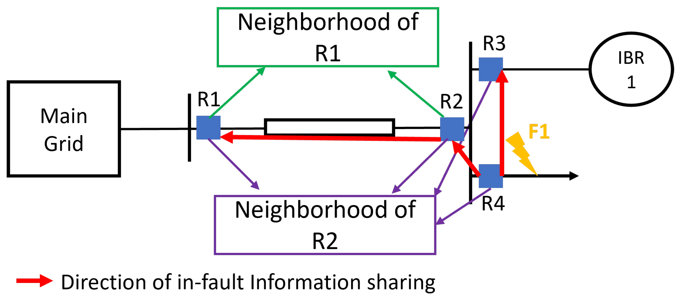
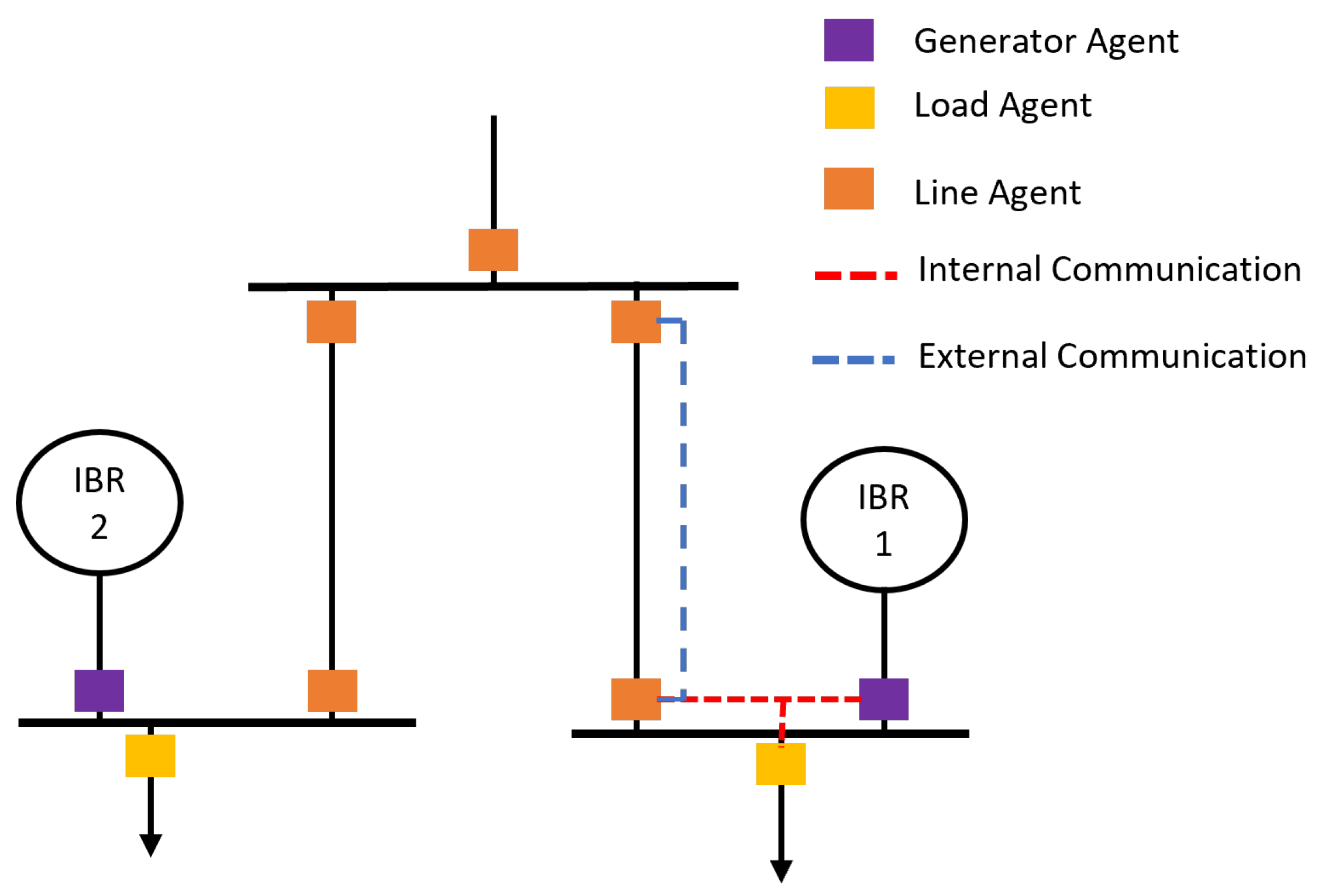
3.1. Distributed Protection Coordination

As discussed in [22], the traditional optimization problem, described in Equations (4) and (5), exhibits two main drawbacks: the complexity arising from the multitude of fault scenarios to analyze and the need for a complete recalculation of the protection system whenever a system reconfiguration occurs. To address these challenges, the distributed optimization theory, discussed in [35,40], and a dynamic matrix representation, based on graph theory, of the operational sequence of protection equipment are employed.
In the framework of distributed optimization theory, the traditional optimal coordination problem adheres to the principle of decomposition, where the operating time per equipment depends solely on local measurements and parameters, facilitating the formulation of smaller and simpler optimization problems distributed among the protection equipment. Furthermore, in addition to distributing the optimization problem, sharing information among neighboring equipment is necessary to ensure the effective operation of the entire protection system.
Considering that all protection equipment remains in fixed locations within a power system, the neighborhood of each equipment is well defined and invariant, enabling the construction of local matrix representations of the desired order of operation by utilizing the direction of information exchange among neighboring equipment. To illustrate this approach, we refer to the two-busbar grid depicted in Figure 1.
Under the assumption that each equipment only possesses information about equipment within its neighborhood, a matrix can be constructed to represent the relative order of operation in fault scenarios and per protection equipment. For instance, the neighborhood of equipment R1 is R2, while the neighborhood of R2 encompass equipment R1, R3, and R4, and so forth. In the fault case F1 and, considering the two protection paths, R4-R2-R1 and R4-R3, the matrices presented in Equations (8) and (9) are constructed representing the relative order of operation:
L ( D 1 ) = 1 1 0 0 , L ( D 2 ) = 1 1 0 0 0 1 0 1 0 0 0 0 0 0 0 0
L ( D 3 ) = 0 0 0 0 1 1 0 0 0 , L ( D 4 ) = 1 0 1 0 1 1 0 0 0
Taking equipment R2 as example, the construction of L ( D 2 ) proceeds as follows: R2 serves as a local primary equipment for R1, sharing its information with R1, which is represented in the matrix as 1 in element [1, 1] and −1 in element [1, 2], indicating that equipment 1 receives information from equipment 2. Simultaneously, R2 acts as a backup equipment for R4, denoted as 1 in element [2, 2] and −1 in element [2, 4], equipment 2 receives information from equipment 4. Finally, equipment R2 neither transmits information to equipment R3 nor R4, nor does it possess information about the data shared with these equipment, represented in the matrix by two zero rows. By conducting a similar analysis, all matrices can be constructed.
The key characteristic of this matrix representation is that it dynamically changes depending on the fault location, changing its elements but not the grade of the matrix, enabling a dynamic portrayal of local equipment operation. This effect, coupled with a distributed optimization problem statement, allows the definition of the distributed coordination problem presented in Equations (10) and (11):
min f l = t l + j N l t j l L
s . t L ( D l ) t T C T I T l L ,
Formalizing the distributed coordination problem statement, the objective function in Equation (10) minimizes the operating times of local equipment within a neighborhood ( N ). In this distributed approach, for local equipment and agent l in agent set L , the objective function comprises its operating time t l and the operating times of the equipment in its neighborhood j N l t j , which are updated during each iteration through information sharing among equipment. Additionally, to simplify the solution and increase the calculation speed of the presented distributed coordination problem, the operating time t l is defined as a defined time function, obtaining a linear and convex optimization problem. Moreover, the constraint set in Equation (11) is defined based on the dynamic matrix L ( D l ) , representing the local operating order or relative fault location with respect to equipment l, a vector of the operating time of the local equipment t T , and the coordination time interval C T I .
To address the distributed coordination problem, a general iterative algorithm is presented in Algorithm 1. In this algorithm, each device independently computes its own operating time, t l , based on the iterative updates of the operating times of neighboring equipment, leveraging the distributed nature of the system.
Algorithm 1: Iteration algorithm for protection equipment l
  • Input:
    1.
    The Laplacian matrix, L ( D l ) , representing the relative order of operation for equipment l.
  • Repeat:
    • Update the operating time t j i of neighboring equipment online for iteration i.
    • Evaluate the current solution.
    • Identify the basic feasible direction d using constraints.
    • Update t l i + 1 = t l i + α d , where α = C T I .
    • Check that all constraints are satisfied.
  • Until  f l i + 1 f l i ϵ , where ϵ is a defined tolerance.
  • End
To effectively integrate this distributed protection coordination algorithm into a protection scheme and fully leverage its characteristics, modified fault detection and direction estimation algorithms are necessary. These will be elaborated upon in the following subsections.

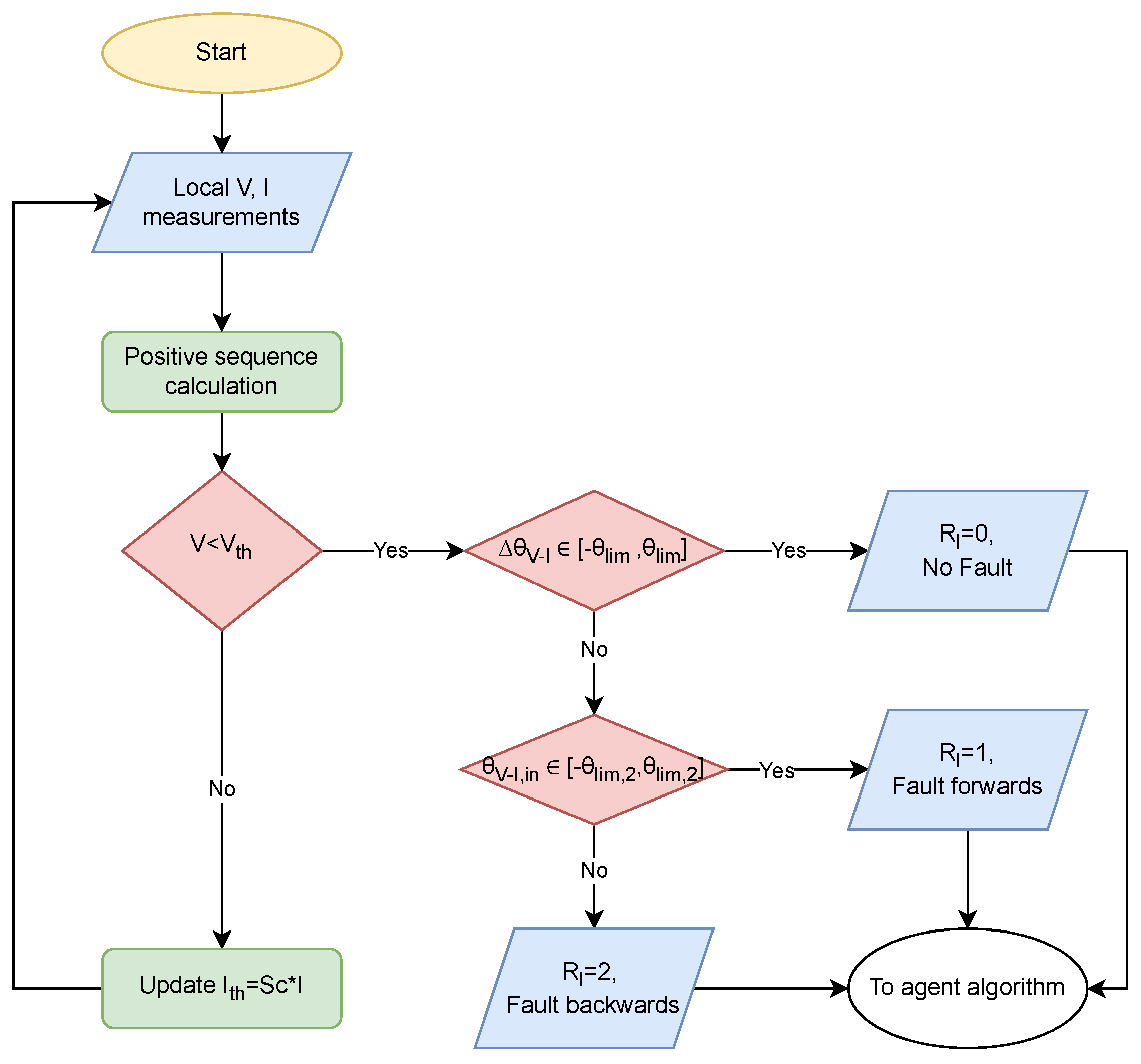
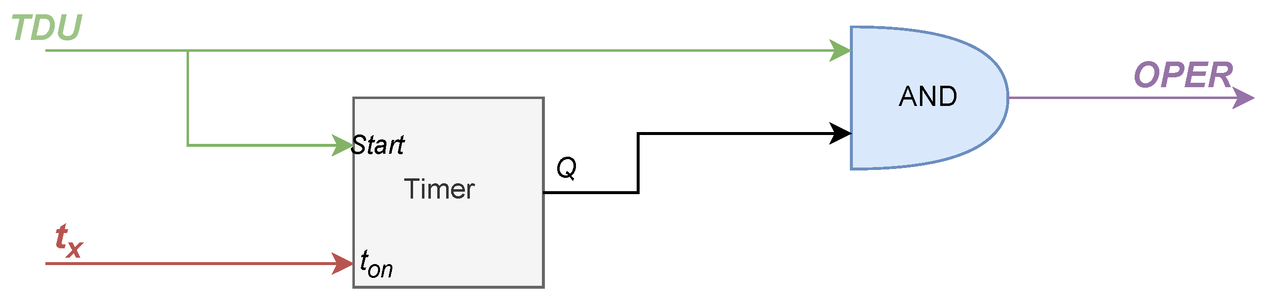
3.2. Fault Detection and Direction Estimation Algorithm

The fault detection algorithm employs a directional overcurrent function, constrained by voltage parameters and integrating a hybrid polarization algorithm. Notably, this algorithm operates without the need for communication links between agents, relying solely on local measurements and calculations.
The flowchart illustrated in Figure 2 outlines the fault detection and direction estimation algorithm always running within each protection device in the system. This algorithm employs positive sequence quantities as decision variables, which are calculated based on local voltage (V) and current (I) measurements. Given that steady-state voltage in a power system should remain within a predefined range under normal conditions, irrespective of load current variations, a traditional under-voltage function serves as the primary detection criterion.
The voltage is used to increase the sensitivity of the overcurrent function. The under-voltage threshold V t h is determined based on the system’s voltage limits. In cases where the measured voltage falls within the normal operational range, the current pickup level I t h is adjusted to increase the sensitivity of an overcurrent function. This adjustment uses the actual measured current I and a security factor ( S c ), enabling the definition of a backup protection function in the event of communication failure. The literature proposes several more sophisticated methods for ensuring redundancy in communication-based primary protection schemes. For instance, Refs. [12,39] discusses communication-less and nonstandard functions.
In the event of fault detection ( V < V t h ), a hybrid direction estimation algorithm is initiated, which uses memorized ( θ V I , p r e ) and self-polarized ( θ V I , i n ) equivalent impedance angles.
Initially, the fault condition is verified by evaluating the change in the positive sequence impedance angle, ( Δ θ V I ), calculated as shown in Equation (12). If this change falls within an established impedance change angle limit, ( θ l i m ), which defines a tolerance band to account for measurement errors, the equipment is considered to be outside the protection path (defined as no-fault state ( R l = 0 )). This outcome is based on the assumption that the equivalent impedance angle should remain relatively constant ( Δ θ V I 0 ) if the fault is outside the equipment’s potential protection paths.
Δ θ V I = θ V I , p r e θ V I , i n ,
Otherwise, when the equipment is inside the required protection path, the angle θ V I , i n is compared against a second angle limit θ l i m , 2 used for distinguishes between forward ( R l = 1 ) and backward ( R l = 2 ) directions. The definition of θ l i m , 2 takes into accounts the fact that a positive active power flow, indicated by 90 θ V I , i n 90 , signifies a forward fault.
The fault detection algorithm described here yields a unique operational state for each protection device, transmitted as a one-byte data element. These states are used to construct the Laplacian matrix representation, which is formed by sharing information among neighboring equipment and is essential for formulating the distributed coordination problem.

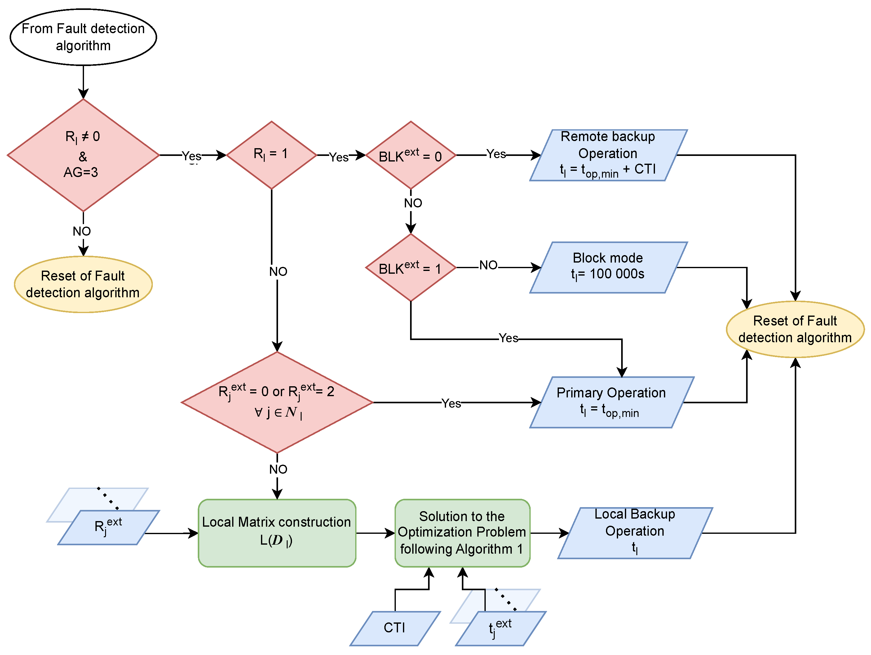
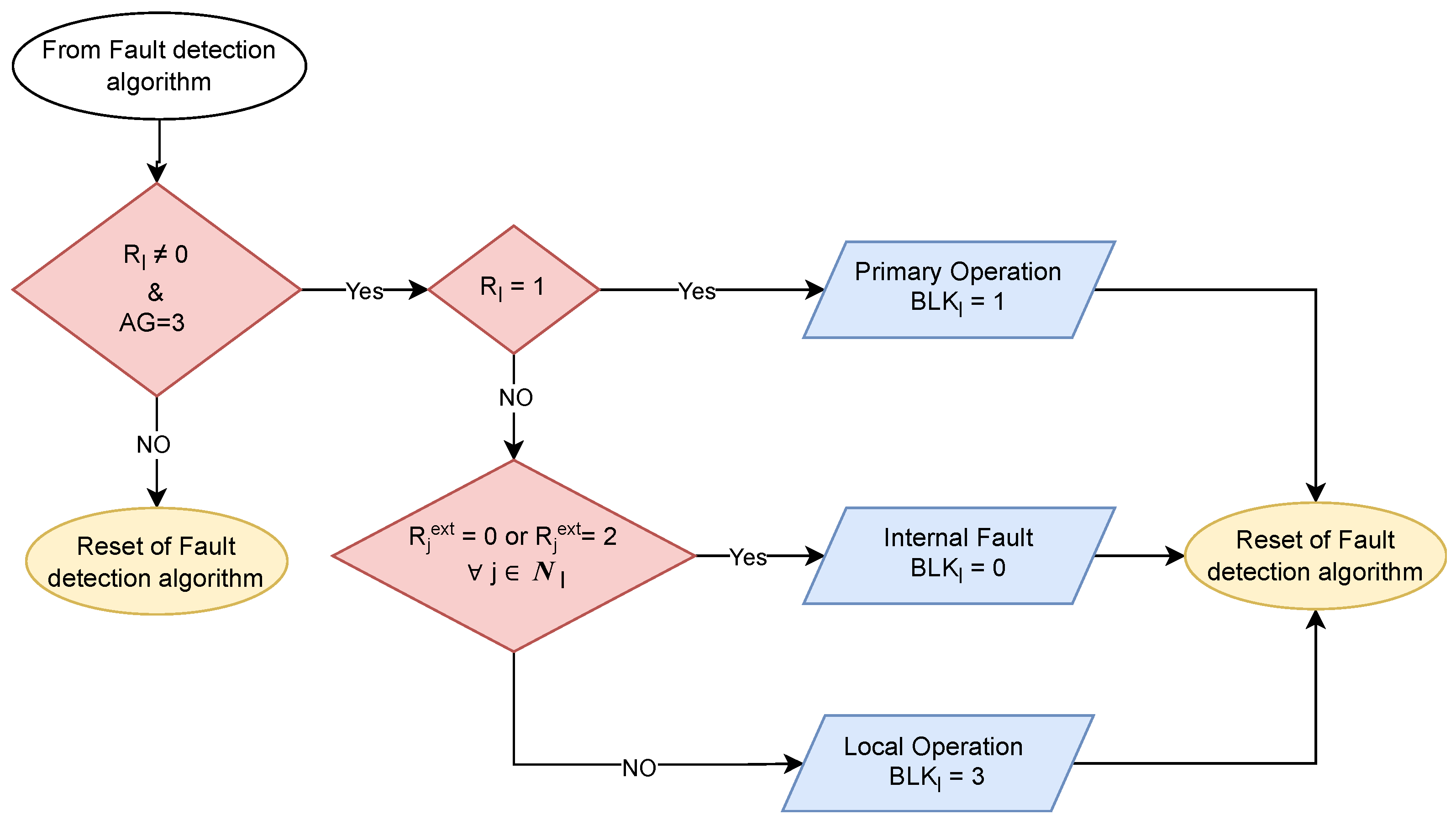
3.3. Online Coordination Algorithm

Following the detection of a fault ( R l 0 ), the local online coordination algorithm is activated. This algorithm employs rules that enhance speed and simplify the optimization process by utilizing the unique operational state of each protection device and a classification system based on agent types. As shown in Figure 3, the protection devices within a system can be categorized into three agent types: generator agents, load agents, and line agents, depending on the type of equipment within the defined protective zone. The coordination algorithm adapts its approach based on the specific agent type, optimizing calculation performance as explained below.
For generator ( A G = 1 ) and load ( A G = 2 ) agents, the algorithm offers two distinct operation modes: primary (when R l = 1 ) and backup (when R l = 2 ), as depicted in Figure 4.
In the primary operation mode, the equipment’s operating time ( t l ) is set to its minimum feasible value ( t o p , m i n ). In the backup operation mode, the operating time is determined using the iterative algorithm for distributed protection coordination outlined in Table 1, which incorporates the operating times of neighboring equipment t j e x t . The solution to this optimization problem relies primarily on the construction of the Laplacian matrix of the digraph, L ( D l ) , which represents the information-sharing directions among the neighboring devices of equipment l. This matrix is constructed based on the unique operating modes ( R j e x t ) of all local neighbors of equipment l.
For line agents ( A G = 3 ), the algorithm defines four operation modes: primary operation, remote backup operation, local backup operation, and block mode, as depicted in Figure 5. These modes are designed to facilitate local backup protection and provide remote protection for internal busbar faults. The mode of operation is determined based on a blocking signal ( B L K e x t ) received from the opposite line agent in the protected line, as well as the operating mode of all local neighbors ( R j e x t ) connected to the equipment under analysis.
In both primary and local backup modes, the equipment’s operating time is determined following the method described earlier for load and generator agents. However, in the case of the remote backup operation mode, the equipment’s operating time is computed as the t o p , m i n plus the CTI, which provides backup to the remote protection equipment. Otherwise, in the block operation mode, the equipment is effectively blocked by setting its operating time to a large number, ensuring a remote coordinated operation.
Following the principles of traditional teleprotection schemes, the line agents also generate a blocking signal. However, instead of simply accelerating or blocking the direct operation of remote equipment, these signals modify the local online coordination decisions, as depicted in Figure 5. Figure 6 illustrates the algorithm that computes the three possible block states of the line agent: primary operation ( B L K l = 1 ), inside fault ( B L K l = 0 ), and local operation ( B L K l = 3 ). These states ensure the proper coordination of the entire protection system by also sharing a one-byte data element between line agents.
To achieve the desired adaptability of the protection system and fully leverage the capabilities of the proposed scheme, the fault detection algorithm operates continuously and autonomously on each protection device. During fault conditions, the algorithm dynamically adjusts the operational states of individual devices and shares their unique operating modes. These dynamic adaptations, in conjunction with the online coordination algorithms described, enable the protection system to respond promptly and effectively to various topological conditions and fault scenarios. As a result, the real-time adjustment of operating times for each device enhances the system’s performance and reliability.

4. Real-Time Simulation Test Bed

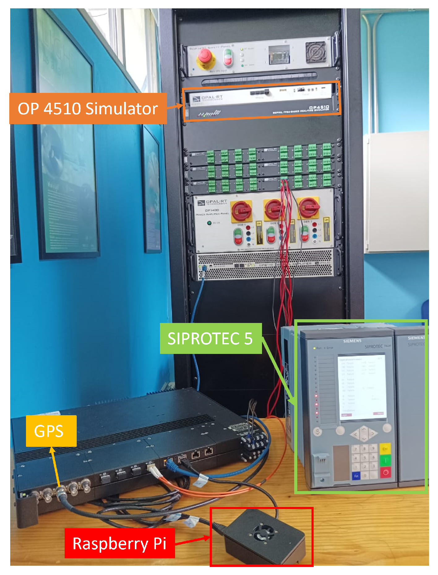
4.1. Experimental Setup
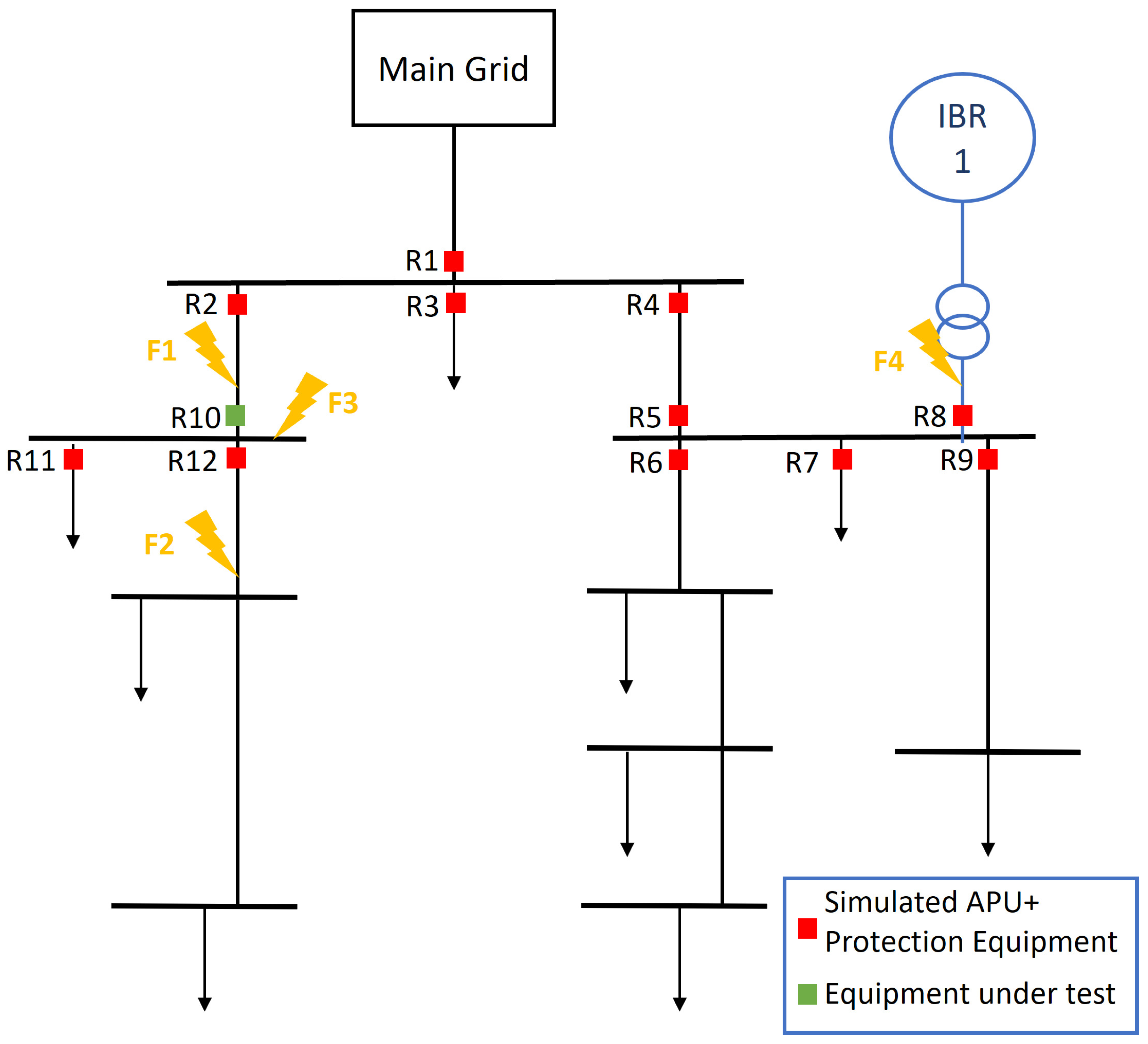
To assess the performance of the proposed protection scheme, the real-time simulation experimental setup depicted in Figure 7, originally introduced in [41], was used. The complete test-bed assembly, shown in Figure 8, consists of an OPAL-RT OP 4510 real-time simulator, a Raspberry Pi 4, a Siemens SIPROTEC 5 protection device, and a Ruggedcom switch.
The OP 4510 unit simulated the selected benchmark and interacted with external hardware using Sampled Values (SVs), Generic Object-Oriented Substation Events (GOOSEs) and Precision Time Protocol (PTP) for synchronization, as per IEC 61869-9 [42], IEC 61850-8-1 [43], and IEEE 1588 [44], respectively. The Raspberry Pi 4 emulates the behavior of an Auxiliary Protection Unit (APU), adding adaptive characteristics to non-adaptive protection devices as governed by the proposed protection scheme. To ensure seamless connection and interaction of the APU with the IEC 61850 process-bus, the open-source library ‘LIBIEC61850’ was employed, as described in [45]. The Siemens SIPROTEC 5 device represents a non-adaptive protection device. Due to firmware limitations, the logic algorithm depicted in Figure 9 was programmed into the SIPROTEC device to achieve the desired adaptive operation. This algorithm utilizes the start command of a standard under-voltage function (TDU) in conjunction with a blocking signal to ensure the timely emission of the tripping command (OPER) at the specified operating time ( t x ) received from the APU. Lastly, the Ruggedcom switch enables the interaction of all elements to form an IEC 61850 process-bus. All models and scripts related to the presented test bed are available for download at [46].

4.2. Study Cases

The simulation scenarios were based on the modified medium-voltage (MV) CIGRE benchmark [47], following the two topological configurations presented in Figure 10 and Figure 11. In this benchmark, a 20 kV distribution system was simulated with a total load of 4.32 MW and 1.43 MVAr. Additionally, two IBRs, each rated at 100 kW, were connected to the distribution system. These IBRs were modeled according to the fault characteristics defined in Section 2.1, with parameters k = 0.97 , a = 3 , and b = 2 . Furthermore, twelve protection devices and their Auxiliary Protection Units (APUs) were simulated in the real-time simulator. The equipment labeled as “equipment under test” in Figure 10 and Figure 11 (highlighted in green) was emulated using a Raspberry Pi and the Siemens SIPROTEC 5 device, which are crucial for the real-time validation of the proposed protection scheme.
For each topological configuration, four low-impedance three-phase fault cases, labeled F1, F2, F3, and F4, were analyzed individually. These eight defined operational scenarios allowed for testing the protection scheme under network reconfiguration, such as the connection of a new IBR, and at different fault locations. This evaluation assessed the construction of the dynamic matrix representation of the fault path and the behavior of all possible decisions within the protection algorithms.
The parameters presented in Table 1 govern the behavior of the algorithms discussed in Section 3. The correction factor S c was selected considering a maximal short circuit current of the IBRs of 1.2 I n . The values of θ l i m and θ l i m , 2 , which are critical for the correct behavior of the proposed protection scheme, were chosen considering the current and voltage measurement errors, the specified polarization direction, and the impedance characteristic of the elements within the system. The minimal operating time t o p , m i n was set close to 0 s to achieve rapid operation. Lastly, the CTI value was selected following standard values, between 300 and 500 ms, looking for a safety operation between the backup and primary equipment [37].
In the context of the proposed test cases, loads are defined with a inductive power factor between 0.9 and 0.95. Furthermore, the orientation of current sensors was specified to identify a forward fault when the fault occurred within the protected element.

5. Test Results and Discussion

In this section, we present the results of the previously defined study cases. By examining the calculated operating times of the APUs and analyzing a time–event diagram that accounts for real calculation and operating times across different fault scenarios, we demonstrate the enhanced characteristics of the proposed protection algorithms.
Table 2 presents the operating times calculated from simulations and emulations of the APUs in the first scenario. These times do not represent the total operating time of the equipment but rather the delay time set by the protection device as a result of the online coordination algorithms and the distributed coordination process. The results demonstrate the effective functioning of the coordinated operation, as evidenced by a staggered operation that ensures compliance with the defined constraints, governed by the CTI of 300 ms between primary and backup equipment.
Furthermore, the computed order of equipment operation enhances the selectivity of the scheme by establishing an appropriate protection path. For instance, in the case of fault F3, which represents a fault in a busbar, the defined operation order allows for the isolation of the smallest part of the system by designating equipment R 10 as the primary protection device. In this scenario, the scheme also identifies two well-coordinated backup devices: R 2 , operating at 310 ms, and R 1 and R 4 , both operating at 610 ms. These results indicate an improvement in system reliability, ensuring that, in the event of a failure in the primary protection equipment, secondary and, in this scheme, tertiary devices can provide system protection without sacrificing selectivity.
In the second scenario, which considers an expanding distribution system, the operating times detailed in Table 3 reaffirm the effectiveness of the proposed protection scheme. Despite the integration of new protection equipment, both emulated and simulated APUs maintain a coordinated operation in all studied cases. These results highlight the adaptive nature of the scheme, demonstrating its capacity to adjust to changes in the system’s topology.
Furthermore, the accurate definition of the required protection paths in all studied scenarios highlights the sensitivity of the protection algorithm. For instance, despite significant changes in the current through device R 10 in fault cases F 1 and F 3 , due to the point of fault and the available fault-current source, the protection algorithm defines a well-suited operation order. This capability demonstrates the protection system’s ability, under the proposed scheme, to identify, track, and accurately respond to changes in fault current levels.
The results of the second scenario also highlight the key benefits of a distributed approach. These advantages include the simplification of the interconnection process for new equipment, which only requires adjustments to the Laplacian matrix size for devices near the newly connected equipment. The coordination process is further simplified by distributing the optimization problem, allowing for the consideration of a smaller set of protection devices. Additionally, potential points of communication failure are minimized by reducing the number of required links between devices. These characteristics align with results previously presented in distributed approaches, such as those in [11].
Lastly, to assess the computational performance of the proposed protection scheme, Figure 12 illustrates the sequence and total duration of operations within the specified real-time test environment, focusing on the most critical fault scenario, F 3 .
At the onset of a fault ( t = 0 s), the APU operating on the Raspberry Pi requires approximately 350 ms to compute and transmit its operating time. This computation time includes the construction of the Laplacian matrix for the local equipment simulated with the Raspberry Pi and the SIPROTEC device. After the Raspberry Pi transmits the calculated time, the SIPROTEC device issues its trip command following a 10 ms delay to account for the fault scenario. Meanwhile, the simulated protection devices on the OPAL-RT platform require an additional 20 ms to calculate and transmit their operating time. This delay corresponds to the time required by the simulated APUs within the OPAL-RT to solve the coordination problem, ensuring a globally staggered operation. When comparing the computation times, it is important to note that the hardware used for the APU implementation has limited computational capacity, as it is based on a low-cost microcontroller. Employing industrial-grade hardware could significantly enhance the speed of the protection system by reducing both computation and communication delays.
When evaluating the actual operating time of the protection system using the time–event diagram, it is concluded that the primary operating time is 360 ms, while the total operating time, including backup operation, amounts to 670 ms. Despite available hardware limitations, the total operating time falls within the expected range when considering the typical damage curves of elements within distribution systems, as the ones presented in [48]. This demonstrates a suitable operational speed that ensures the general safety of the distribution system components.
Overall, the results demonstrate the enhanced adaptability of the protection system, ensuring coordinated, selective, and well-organized operation across all studied scenarios, including network reconfiguration. Furthermore, considering the real-time validation setup, where a non-adaptive protection device is used, the proposed protection algorithm successfully modifies the parameters of this device dynamically, providing the desired adaptability. With these features, the proposed scheme exhibits promising performance, aligning with the primary objective of establishing a simpler and more adaptive coordinated protection system, validated under three-phase fault conditions.

6. Conclusions

This study introduced a communication-based adaptive protection scheme designed to address the challenges of protecting active distribution networks. The scheme was rigorously evaluated using a Controller Hardware-In-the-Loop (CHIL) test bed incorporating the IEC 61850 communication protocol. Hardware validation included a setup featuring a Raspberry Pi with an embedded APU and a SIPROTEC 5 device. The findings confirm that the scheme meets its primary objectives: it enhances the adaptability of the protection system, as demonstrated by the proper coordination and effective operation of protection devices across all fault scenarios, including those in expanding systems. Additionally, the communication system requirements are simplified by reducing the necessary bandwidth and leveraging a distributed architecture.
Moreover, the results from the studied cases demonstrate that the protection scheme maintains protection sensitivity, improves reliability by coordinating multiple backup units, introduces adaptive capabilities to traditionally non-adaptive equipment, reduces communication system complexity, and ensures suitable operational speed. A major contribution of this work is the demonstration that the proposed protection scheme provides a straightforward solution for incorporating adaptive characteristics into non-adaptive protection devices. Additionally, the CHIL test bed proved to be an effective platform, underscoring its potential for future research into the protection of active distribution systems, particularly in the application of digital substation concepts.
Despite the promising results, challenges remain. Future work will focus on enhancing the proposed scheme to manage unbalanced fault scenarios and evaluating its performance under communication failures. Additionally, more sophisticated techniques for fault detection and classification, as suggested in [49,50], will be explored. The development of advanced offline backup schemes to increase the reliability of the proposed protection system will also be pursued. These efforts will contribute to refining the scheme’s adaptability and robustness under diverse operational conditions.

Author Contributions

Conceptualization, M.A.-I., D.R.-Q. and C.A.C.; formal analysis, M.A.-I.; funding acquisition, D.R.-Q. and C.A.C.; methodology, M.A.-I.; software, M.A.-I.; supervision, D.R.-Q. and C.A.C.; validation, M.A.-I.; writing—original draft, M.A.-I.; writing—review and editing, D.R.-Q. and C.A.C. All authors have read and agreed to the published version of the manuscript.

Funding

This work was funded by the Colombian Government through the Sistema general de Regalías (SGR), within the project “Diseño e implementación de microrredes eléctricas para garantizar la calidad del suministro en cargas críticas del Vichada-BPIN 2020000100064”.

Data Availability Statement

The original contributions presented in the study are included in the article, further inquiries can be directed to the corresponding author.

Acknowledgments

We extend our sincere gratitude to the Universidad Nacional de Colombia, with special appreciation to the research group EMC-UN and the laboratory “Laboratorio de Innovación en Alta Tensión y Energías Renovables (LIATER)” for their invaluable support and provision of facilities.

Conflicts of Interest

The authors declare no conflicts of interest. The funders had no role in the design of the study; in the collection, analyses, or interpretation of data; in the writing of the manuscript; or in the decision to publish the results.

Nomenclature

ADNActive distribution network
APUAuxiliary Protection Unit
CHILController Hardware-In-the-Loop
CIGREInternational Council on Large Electric Systems
CTICoordination time interval
GOOSEsGeneric Object-Oriented Substation Events
IBRInverter-based resource
IIDGInverter-interfaced distributed generator
MASMulti-agent-based system
PTPPrecision Time Protocol
SGSetting group
SVsSampled Values

References

  1. Hamanah, W.M.; Hossain, M.I.; Shafiullah, M.; Abido, M.A. AC Microgrid Protection Schemes: A Comprehensive Review. IEEE Access 2023, 11, 76842–76868. [Google Scholar] [CrossRef]
  2. Manson, S.; McCullough, E. Practical Microgrid Protection Solutions: Promises and Challenges. IEEE Power Energy Mag. 2021, 19, 58–69. [Google Scholar] [CrossRef]
  3. Wong, J.Y.R.; Tan, C.K.; Bakar, A.H.A.; Che, H.S. Selectivity Problem in Adaptive Overcurrent Protection for Microgrid with Inverter-Based Distributed Generators (IBDG): Theoretical Investigation and HIL Verification. IEEE Trans. Power Deliv. 2022, 37, 3313–3324. [Google Scholar] [CrossRef]
  4. Samadi, A.; Chabanloo, R.M. Adaptive coordination of overcurrent relays in active distribution networks based on independent change of relays’ setting groups. Int. J. Electr. Power Energy Syst. 2020, 120, 106026. [Google Scholar] [CrossRef]
  5. Chandraratne, C.; Logenthiran, T.; Naayagi, R.T.; Woo, W.L. Overview of Adaptive Protection System for Modern Power Systems. In Proceedings of the International Conference on Innovative Smart Grid Technologies, ISGT Asia, Singapore, 22–25 May 2018. [Google Scholar] [CrossRef]
  6. Aminifar, F.; Teimourzadeh, S.; Shahsavari, A.; Savaghebi, M.; Golsorkhi, M.S. Machine learning for protection of distribution networks and power electronics-interfaced systems. Electr. J. 2021, 34, 106886. [Google Scholar] [CrossRef]
  7. Cao, H.; Zhang, D.; Yi, S. Real-Time Machine Learning-based fault Detection, Classification, and locating in large scale solar Energy-Based Systems: Digital twin simulation. Solar Energy 2023, 251, 77–85. [Google Scholar] [CrossRef]
  8. Sadoughi, M.; Hojjat, M.; Abardeh, M.H. Smart overcurrent relay for operating in islanded and grid-connected modes of a micro-grid without needing communication systems. Energy Syst. 2022, 13, 31–51. [Google Scholar] [CrossRef]
  9. Marín-Quintero, J.; Orozco-Henao, C.; Velez, J.C.; Bretas, A. Micro grids decentralized hybrid data-driven cuckoo search based adaptive protection model. Int. J. Electr. Power Energy Syst. 2021, 130, 106960. [Google Scholar] [CrossRef]
  10. Wang, X.; Luan, K. Setting Optimization of Distribution Network Current Protection Based on Constrained Multi-Objectives Backbone Particle Swarm Optimization. IEEJ Trans. Electr. Electron. Eng. 2024, 19, 318–326. [Google Scholar] [CrossRef]
  11. Ataei, M.A.; Gitizadeh, M. A distributed adaptive protection scheme based on multi-agent system for distribution networks in the presence of distributed generations. IET Gener. Transm. Distrib. 2022, 16, 1521–1540. [Google Scholar] [CrossRef]
  12. Barranco-Carlos, A.; Orozco-Henao, C.; Marín-Quintero, J.; Mora-Flórez, J.; Herrera-Orozco, A. Adaptive Protection for Active Distribution Networks: An Approach Based on Fuses and Relays with Multiple Setting Groups. IEEE Access 2023, 11, 31075–31091. [Google Scholar] [CrossRef]
  13. Gutierrez-Rojas, D.; Nardelli, P.H.J.; Mendes, G.; Popovski, P. Review of the State of the Art on Adaptive Protection for Microgrids Based on Communications. IEEE Trans. Ind. Inform. 2021, 17, 1539–1552. [Google Scholar] [CrossRef]
  14. Eslami, R.; Hosseini, S.A. A Comprehensive Method for Fault Detection in AC/DC Hybrid Microgrid. Electr. Power Components Syst. 2022, 50, 38–51. [Google Scholar] [CrossRef]
  15. dos Reis, F.B.; Pinto, J.O.C.; dos Reis, F.S.; Issicaba, D.; Rolim, J.G. Multi-agent dual strategy based adaptive protection for microgrids. Sustain. Energy Grids Netw. 2021, 27, 100501. [Google Scholar] [CrossRef]
  16. Dizioli, F.A.; Barra, P.H.; Menezes, T.S.; Lacerda, V.A.; Coury, D.V.; Fernandes, R.A. Multi-agent system-based microgrid protection using angular variation: An embedded approach. Electr. Power Syst. Res. 2023, 220, 109324. [Google Scholar] [CrossRef]
  17. Wan, H.; Li, K.K.; Wong, K.P. An Adaptive Multiagent Approach to Protection Relay Coordination With Distributed Generators in Industrial Power Distribution System. IEEE Trans. Ind. Appl. 2010, 46, 2118–2124. [Google Scholar] [CrossRef]
  18. Zamani, M.A.; Yazdani, A.; Sidhu, T.S. A communication-assisted protection strategy for inverter-based medium-voltage microgrids. IEEE Trans. Smart Grid 2012, 3, 2088–2099. [Google Scholar] [CrossRef]
  19. Wang, W.; Lu, Z. Cyber security in the Smart Grid: Survey and challenges. Comput. Netw. 2013, 57, 1344–1371. [Google Scholar] [CrossRef]
  20. Lu, Z.; Wang, J.; Shahidehpour, M.; Bai, L.; Xiao, Y.; Li, H. Cooperative Operation of Distributed Energy Resources and Thermal Power Plant With a Carbon-Capture-Utilization-and-Storage System. IEEE Trans. Power Syst. 2024, 39, 1850–1866. [Google Scholar] [CrossRef]
  21. Duan, Y.; Zhao, Y.; Hu, J. An initialization-free distributed algorithm for dynamic economic dispatch problems in microgrid: Modeling, optimization and analysis. Sustain. Energy Grids Netw. 2023, 34, 101004. [Google Scholar] [CrossRef]
  22. Acevedo-Iles, M.; Romero-Quete, D.; Mojica-Nava, E.; Cortes, C.A. Distributed Protection Coordination Algorithm Applied to Overcurrent-Based Schemes. In Proceedings of the 2023 IEEE Belgrade PowerTech, Belgrade, Serbia, 25–29 June 2023; pp. 1–6. [Google Scholar] [CrossRef]
  23. Mahamedi, B.; Zhu, J.G.; Eskandari, M.; Li, L.; Mehrizi-Sani, A. Analysis of fault response of inverter-interfaced distributed generators in sequence networks. In Proceedings of the 2018 IEEE Industry Applications Society Annual Meeting (IAS), Portland, OR, USA, 23–27 September 2018. [Google Scholar] [CrossRef]
  24. Nimpitiwan, N.; Heydt, G.T.; Ayyanar, R.; Suryanarayanan, S. Fault current contribution from synchronous machine and inverter based distributed generators. IEEE Trans. Power Deliv. 2007, 22, 634–641. [Google Scholar] [CrossRef]
  25. Khan, M.A.U.; Hong, Q.; Egea-Àlvarez, A.; Dyśko, A.; Booth, C. A communication-free active unit protection scheme for inverter dominated islanded microgrids. Int. J. Electr. Power Energy Syst. 2022, 142, 108125. [Google Scholar] [CrossRef]
  26. Association, I.S. IEEE Std. 1547-2018; Standard for Interconnection and Interoperability of Distributed Energy Resources with Associated Electric Power Systems Interfaces. IEEE: Piscataway, NJ, USA, 2018.
  27. Rathnayake, D.B.; Akrami, M.; Phurailatpam, C.; Me, S.P.; Hadavi, S.; Jayasinghe, G.; Zabihi, S.; Bahrani, B. Grid Forming Inverter Modeling, Control, and Applications. IEEE Access 2021, 9, 114781–114807. [Google Scholar] [CrossRef]
  28. Furlaneto, R.; Kocar, I.; Grilo-Pavani, A.; Karaagac, U.; Haddadi, A.; Farantatos, E. Short circuit network equivalents of systems with inverter-based resources. Electr. Power Syst. Res. 2021, 199, 107314. [Google Scholar] [CrossRef]
  29. Pattabiraman, D.; Lasseter, R.H.; Jahns, T.M. Transient Stability Modeling of Droop-Controlled Grid-Forming Inverters with Fault Current Limiting. In Proceedings of the 2020 IEEE Power & Energy Society General Meeting (PESGM), Montreal, QC, Canada, 2–6 August 2020; pp. 1–5. [Google Scholar] [CrossRef]
  30. Just, H. Modeling and Control of Power Converters in Weak and Unbalanced Electric Grids; Universitätsverlag der Technischen Universität Berlin: Berlin, Germany, 2021. [Google Scholar] [CrossRef]
  31. Kabiri, R.; Holmes, D.G.; McGrath, B.P. Control of Active and Reactive Power Ripple to Mitigate Unbalanced Grid Voltages. IEEE Trans. Ind. Appl. 2016, 52, 1660–1668. [Google Scholar] [CrossRef]
  32. Haddadi, A.; Zhao, M.; Kocar, I.; Farantatos, E.; Martinez, F. Impact of Inverter-Based Resources on Memory-Polarized Distance and Directional Protective Relay Elements. In Proceedings of the 2020 52nd North American Power Symposium, NAPS 2020, Tempe, AZ, USA, 11–13 April 2021. [Google Scholar] [CrossRef]
  33. Haddadi, A.; Kocar, I.; Mahseredjian, J.; Karaagac, U.; Farantatos, E. Performance of phase comparison line protection under inverter-based resources and impact of the german grid code. In Proceedings of the IEEE Power and Energy Society General Meeting, Montreal, QC, Canada, 2–6 August 2020. [Google Scholar] [CrossRef]
  34. Rezaeieh, M.R.H.; Bolandi, T.G.; Jalalat, S.M. A novel approach for resilient protection of AC microgrid based on differential phase angle of superimposed complex power. Sustain. Energy Grids Netw. 2023, 34, 101024. [Google Scholar] [CrossRef]
  35. Mojica-Nava, E. Optimización y Control en Grafos; Editorial UN: Bogotá, Colombia, 2022. [Google Scholar]
  36. Ellis-Monaghan, J.A.; Moffatt, I. Handbook of the Tutte Polynomial and Related Topics; Chapman and Hall/CRC: London, UK, 2022. [Google Scholar] [CrossRef]
  37. IEEE Std 242-2001; IEEE Recommended Practice for Protection and Coordination of Industrial and Commercial Power Systems (IEEE Buff Book). (Revision of IEEE Std 242-1986) [IEEE Buff Book]; IEEE: Piscataway, NJ, USA, 2001; pp. 1–710. [CrossRef]
  38. Kumar, P.; Rana, A.S. Review of optimization techniques for relay coordination in consideration with adaptive schemes of Microgrid. Electr. Power Syst. Res. 2024, 230, 110240. [Google Scholar] [CrossRef]
  39. Biswal, S.; Samantaray, S.R. An Effective Protection Coordination Scheme for Networked Microgrids Based on Nonstandard Tripping Characteristics of DOCRs. IEEE Syst. J. 2023, 17, 6588–6599. [Google Scholar] [CrossRef]
  40. Boyd, S.; Parikh, N.; Chu, E.; Peleato, B.; Eckstein, J. Distributed optimization and statistical learning via the alternating direction method of multipliers. Found. Trends Mach. Learn. 2010, 3, 1–122. [Google Scholar] [CrossRef]
  41. Barra, P.; Lacerda, V.; Fernandes, R.; Coury, D. A hardware-in-the-loop testbed for microgrid protection considering non-standard curves. Electr. Power Syst. Res. 2021, 196, 107242. [Google Scholar] [CrossRef]
  42. IEC 61869-9; Instrument Transformers-Part 9: Digital Interface for Instrument Transformers. IEC: Geneva, Switzerland, 2016.
  43. IEC 61850-8-1; Communication Networks and Systems for Power Utility Automation—Part 8-1: Specific Communication Service Mapping (SCSM)—Mappings to MMS (ISO 9506-1 and ISO 9506-2) and to ISO/IEC 8802-3. IEC: Geneva, Switzerland, 2011.
  44. IEEE 1588; IEEE Standard for a Precision Clock Synchronization Protocol for Networked Measurement and Control Systems. (Revision of IEEE Std 1588-2002); IEEE: Piscataway, NJ, USA, 2008.
  45. Zillgith, M. Libiec61850/Lib60870 Open Source Libraries for IEC 61850 and IEC 60870-5-101/104. Available online: https://libiec61850.com/ (accessed on 25 November 2023).
  46. Acevedo-Iles, M.; Romero-Quete, D.; Cortes, C.A. Open-Source Code of an Adaptive Protection Scheme Using LIBIEC61850. 2023. Available online: https://github.com/ManuAce9/Integral-Protection-Scheme (accessed on 15 December 2023).
  47. Conseil International Des Grands Réseaux Électriques. Benchmark Systems for Network Integration of Renewable and Distributed Energy Resources; CIGRÉ: Paris, France, 2014; Available online: https://www.e-cigre.org/publications/detail/575-benchmark-systems-for-network-integration-of-renewable-and-distributed-energy-resources.html (accessed on 15 January 2023).
  48. IEEE Std C57.109-1993; IEEE Guide for Liquid-Immersed Transformers Through-Fault-Current Duration. IEEE: Piscataway, NJ, USA, 1993; pp. 1–125. [CrossRef]
  49. Marín-Quintero, J.; Orozco-Henao, C.; Percybrooks, W.S.; Vélez, J.C.; Montoya, O.D.; Gil-González, W. Toward an adaptive protection scheme in active distribution networks: Intelligent approach fault detector. Appl. Soft Comput. 2021, 98, 106839. [Google Scholar] [CrossRef]
  50. Huang, Z.; Dong, L.; Yao, X. Reversed trend comprehensive assessment-based inverter fault diagnosis under various complex interferences in microgrid. Meas. J. Int. Meas. Confed. 2024, 228, 114301. [Google Scholar] [CrossRef]
Figure 1. Two-busbar example grid for local matrix construction.
Energies 17 04338 g001
Figure 2. Proposed algorithm for fault detection.
Energies 17 04338 g002
Figure 3. Example of a three-busbar system illustrating the directional overcurrent topology and agent-type classification.
Energies 17 04338 g003
Figure 4. Online coordination algorithm for load and generator agents.
Energies 17 04338 g004
Figure 5. Online coordination algorithm for line agent.
Energies 17 04338 g005
Figure 6. Algorithm for blocking signal generation in line agent.
Energies 17 04338 g006
Figure 7. Schematic diagram of the proposed experimental setup.
Energies 17 04338 g007
Figure 8. Complete assembled test bed.
Energies 17 04338 g008
Figure 9. Logic diagram for adaptive operation of the Siprotec 5 device.
Energies 17 04338 g009
Figure 10. Modified CIGRE MV benchmark—first network configuration scenario.
Energies 17 04338 g010
Figure 11. Modified CIGRE MV benchmark—second network configuration scenario.
Energies 17 04338 g011
Figure 12. Example time–event diagram for fault F3, defining the emulated APU as the primary operation.
Energies 17 04338 g012
Table 1. Defined algorithm parameters.
ParameterValue
Sc 1.2
θ l i m 5
θ l i m , 2 92
t o p , m i n 10 ms
C T I 300 ms
Table 2. Operating times for primary and backup protection equipment in Scenario 1.
Fault CaseScenario 1
Primary Equipment Operating Time (ms) Backup Equipment Operating Time (ms)
F1 t R 2 = 10 t R 1 = 310
t R 4 = 310
F2 t R 12 = 10 t R 10 = 310
F3 t R 10 = 10 t R 2 = 310 t R 1 = 610
t R 4 = 610
F4 t R 8 = 10 t R 5 = 310
Table 3. Operating times for primary and backup protection equipment in Scenario 2.
Fault CaseScenario 2
Primary Equipment Operating Time (ms)Backup Equipment Operating Time (ms)
F1 t R 2 = 10 t R 1 = 310
t R 4 = 310
t R 10 = 10 t R 13 = 310
F2 t R 12 = 10 t R 10 = 310
t R 13 = 310
F3 t R 10 = 10 t R 2 = 310 t R 1 = 610
t R 4 = 610
t R 13 = 10
F4 t R 8 = 10 t R 5 = 310
Disclaimer/Publisher’s Note: The statements, opinions and data contained in all publications are solely those of the individual author(s) and contributor(s) and not of MDPI and/or the editor(s). MDPI and/or the editor(s) disclaim responsibility for any injury to people or property resulting from any ideas, methods, instructions or products referred to in the content.

