Article

Research on Reactive Power Optimization of Synchronous Condensers in HVDC Transmission Based on Reactive Power Conversion Factor

1
College of Electrical Engineering and New Energy, China Three Gorges University, Yichang 443002, China
2
Electric Power Research Institute, State Grid Hubei Electric Power Co., Ltd., Wuhan 430077, China
*
Author to whom correspondence should be addressed.
Energies 2024, 17(17), 4294; https://doi.org/10.3390/en17174294
Submission received: 7 August 2024 / Revised: 22 August 2024 / Accepted: 26 August 2024 / Published: 28 August 2024
(This article belongs to the Section F6: High Voltage)

Abstract

:
With the rapid development of high-voltage direct current (HVDC) transmission systems, the coupling between AC and DC grids is becoming increasingly close. Voltage disturbances in the grid can easily cause commutation failures in the DC system, threatening its safe and stable operation. The new generation of synchronous condensers (SCs) and modified synchronous condenser units are powerful reactive power support devices widely used in large-capacity DC transmission systems. To maximize the voltage support and commutation failure suppression of SCs, this paper proposes improvements in the initial operating state of SCs, using the Shanxi–Wuhan HVDC receiving end in the Hubei power grid as an example, to better support the HVDC commutation process. Additionally, a reactive power output optimization strategy for SCs is proposed, considering the reactive power equivalent factor of electrical connections between grid nodes. This strategy determines the optimal reactive power output limit of SCs near the converter station to suppress DC commutation failures. Simulation results show that this strategy effectively utilizes the dynamic support capabilities of SCs, prevents DC commutation failures, improves HVDC transmission capacity, and enhances the safety and stability of the receiving end power grid, providing theoretical guidance for reactive power output control.

1. Introduction

Under the guidance of the “One Ultra High Voltage (UHV) and Four Large” strategy of the State Grid Corporation of China, our country has entered a period of large-scale construction of UHV AC and DC transmission projects. Since July 2010, when the first UHVDC transmission project in China, the Xiangjiaba–Shanghai ±800 kV UHVDC demonstration project, was completed and officially put into commercial operation, multiple ±800 kV UHVDC projects have been successively constructed and put into operation. The structure of China’s power grid has gradually developed into a hybrid AC–DC large power grid connected by a UHV main grid.
The advancement of modern AC–DC power grids has introduced a series of new challenges in operational control, leading to an increase in the frequency of grid failures [1]. From an inter-regional perspective, the imbalance between AC and DC development has resulted in a pronounced ‘strong DC, weak AC’ characteristic in our country, complicating grid operation and control measures [2,3]. When the receiving grid is weak, continuous load growth and an increasing reliance on external power sources can pose a significant risk of voltage instability [4] and even DC commutation failure. In ultra-high voltage direct current (UHVDC) transmission systems, commutation failures rarely occur on the rectifier side due to the operating characteristics of thyristors. However, they are more likely to occur on the inverter side, where they can lead to very serious consequences, including DC commutation failure [5]. To address the significant challenges of insufficient dynamic reactive power reserves and inadequate voltage support at both the sending and receiving ends of UHVDC systems in China, it is essential to ensure adequate large-scale dynamic reactive power under conditions of extensive DC power transmission [6,7], namely “large-scale DC transmission, strong reactive power support. To address this challenge, China has planned and constructed multiple synchronous condensers (SCs) for upcoming UHVDC projects. Additionally, converting underutilized thermal power units into synchronous condensers has emerged as a viable solution [8,9].
Currently, the role of SCs in reactive power compensation in UHVDC transmission systems is very significant [10]. Considering the reactive power output of synchronous condensers (SCs) and the demands of the power grid, high-power SCs, as synchronous rotating machines, are capable of providing substantial short-circuit capacity and dynamic voltage support for large regional power grids [11,12]. The dynamic reactive power output capability of synchronous condensers (SCs) and their role in supporting transient voltage changes in the power system are directly determined by dynamic parameters [13,14]. Large DC weak receiving-end systems demand that synchronous condensers (SCs) not only possess a sufficient reactive power adjustment range but also exhibit favorable subtransient and transient reactive power characteristics. The key parameters of SCs significantly influence their reactive power adjustment capabilities, which in turn impacts the reactive power requirements of the power grid [15,16]. Most existing studies focus on the installation location and capacity optimization of synchronous condensers under steady-state conditions without considering the involvement of emergency control after accidents. There is little research on the impact mechanism of inherent parameters such as transient/subtransient reactance of SCs on voltage support and recovery under fault conditions.
Ref. [17] introduces the control strategies and configuration of capacitor banks, taking a DC converter station as an example. It details the field control methods, test procedures, and contents of the AVC system for large capacitor bank converter stations. Using this as a basis to enhance the reactive power support capability of a synchronous condenser. However, it does not propose an overall control approach for the integrated system involving both reactive power compensation devices and the AVC system. Ref. [18] investigates the impact of excitation system parameters on the dynamic reactive power of a new type of synchronous condenser and proposes the steady-state reactive power output levels and transient response characteristics of the new synchronous condenser under different excitation parameters. The research identifies the optimization direction for the excitation system parameters of the synchronous condenser. However, it does not address the operating conditions suitable for parameter optimization or the optimization strategy for the synchronous condenser in the event of a fault. Ref. [19] proposes a method for automatically optimizing the size and position of synchronous condensers (SCs) to meet the minimum grid strength requirements needed for high penetration of inverter-based resources (IBRs) in weak power grids. However, the method does not take into account the screening of the motor and emergency control after a fault occurs. Ref. [20] proposes a DC control system and SC coordination control scheme, indicating that a synchronous condenser can provide continuously adjustable dynamic reactive power support, thereby avoiding the risk of grid voltage drop exceeding the limit. However, the paper does not delve deeply into how to regulate the reactive power output characteristics of the SC using critical indicators.
This paper addresses the voltage stability issues in UHVDC receiving end grids, especially the occurrence of DC commutation failures [21,22], using the UHVDC receiving end Hubei power grid as an example. Based on the derivation of the reactive power equivalent factor considering the mutual influence of grid nodes, an optimization strategy for the reactive power output of SC is proposed. This strategy, on the one hand, selects suitable SC units for regulation by targeting the transient links of system faults, and on the other hand, restricts the transient reactive power compensation capability of SC units within an optimized range through reactive power optimization indices, thereby enhancing system stability. Finally, simulation verification is carried out in practical power grid operation cases, first studying the operating characteristics of the power grid under different initial reactive power conditions of SC and proposing initial reactive power optimization suggestions for SC. Further verification is conducted to see if the proposed strategy can suppress commutation failure and provide metric-based evidence for SC reactive power regulation and unit conversion to SC. The results show that reasonable control of SC initial reactive power and transient reactive response can fully utilize the effectiveness of SC, enhance system voltage stability, and ensure the operational safety of UHV grid equipment.

2. Reactive Power Output Characteristics of SC

When a fault occurs near the AC grid or when the converter valve experiences a commutation failure resulting in a voltage drop, a large-capacity synchronous condenser can provide strong excitation support to maintain voltage and system stability, thereby gaining valuable time for fault clearance [23].

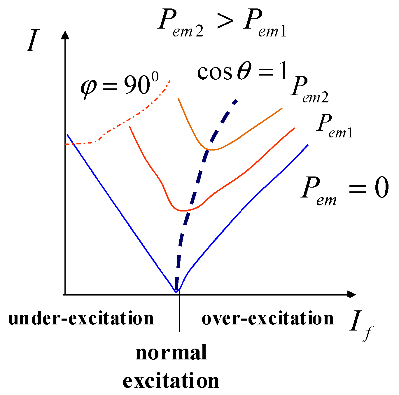
2.1. Reactive Power Regulation and Control of SC

When the active power output of the SC remains constant, adjusting its excitation current can change the potential, thereby regulating the nature and magnitude of reactive power. For example, in Figure 1, the right side of the V-shaped curve represents the over-excitation region, where the SC delivers inductive reactive power; the left side represents the under-excitation region, where the SC absorbs inductive reactive power.
The equivalent circuit of a conventional synchronous condenser (SC) participating in reactive power regulation for a high-voltage direct current (HVDC) converter station and its AC grid is shown in Figure 2. The SC and its step-up transformer are outlined in the frame, with Qsc representing the reactive power injected into the converter station. In the event of a fault in the DC system or the disconnection of active loads, the SC enters a leading power factor mode, absorbing a large amount of surplus reactive power to suppress system voltage rise [24]. During normal operation, it can provide continuous and adjustable dynamic reactive support to the AC grid through either lagging or leading power factor operation [25,26]. Additionally, during faults, the SC can raise the system’s minimum voltage, thereby reducing the probability of DC system commutation failure.
SC can comprehensively enhance the system’s dynamic reactive power reserve and address various voltage stability issues. The excellent reactive power support capability of SC requires an effective reactive power control strategy. Therefore, the key research focus is on how to regulate and optimize the reactive power output of SC during both steady-state and transient processes following faults to support stable grid operation.

2.2. Relationship between Reactive Power Output Characteristics and Key Performance Parameters of the Unit

To fully illustrate the adaptability of a large-capacity synchronous condenser to the reactive power demand at the sending and receiving ends of ultra-high-voltage direct current (UHVDC) transmission systems, it is first necessary to clarify the key performance parameters related to the reactive power output characteristics of these capacity synchronous condensers.
Considering that the large-capacity synchronous condenser uses a static self-excited excitation system, the excitation voltage is controlled by collecting the terminal voltage Ut of the transformer. Based on the single-machine-infinite-bus system structure, the reactive power Q can be expressed in terms of the terminal voltage Ut and the total reactance of the transformer and line XL.
Q = U t 2 X L U t 2 U X L cos δ L
when the synchronous condenser is a hidden pole machine structure, it can be assumed that XL = Xd = Xq. Therefore, it can be seen from the formula that the reactive power output capability of a large-capacity synchronous condenser is primarily related to the direct-axis synchronous reactance Xd. The smaller Xd is, the larger the steady-state reactive power output limit of the large-capacity synchronous condenser will be.
According to the superposition principle, when there is a sudden change in the terminal voltage of a synchronous motor, it is equivalent to suddenly applying an opposing voltage at the terminal. Assuming that the terminal voltage vector of the synchronous condenser is U0 during steady-state operation, and during a system fault, the terminal voltage changes from U0 to KU0, where K represents the degree of change in the grid voltage. Thus, during the system fault, relative to suddenly applying a voltage of U = (K − 1)U0 at the terminal of the synchronous condenser, the following result can be obtained.
0 = p ψ d ψ q u q = ( K 1 ) U 0 = p ψ q + ψ d
Due to the relatively large time constant of the excitation circuit response, the excitation voltage response delay is 20 to 60 milliseconds. Therefore, when there is a sudden change in the terminal voltage, the effect of excitation voltage adjustment can be ignored. At this moment, the magnetic flux equation of the motor is as follows:
ψ d = X d ( p ) i d ψ q = X q ( p ) i q
Combining the above equations, we obtain the following:
i d = ( K 1 ) U 0 X d ( p ) ( p 2 + 1 ) i q = p ( K 1 ) U 0 X q ( p ) ( p 2 + 1 )
In the instant of sudden changes in the grid voltage, the rotor windings are equivalent to a superconducting circuit (setting the rotor resistance to zero). After considering the excitation windings, longitudinal axis-damping windings, and transverse axis-damping windings on the rotor, the longitudinal axis operating reactance Xd(p) and the transverse axis operating reactance Xq(p) can be expressed as follows:
X d ( p ) = X l + 1 1 X ad + 1 X f l + 1 X dl = X d X q ( p ) = X l + 1 1 X aq + 1 X ql = X q
The synchronous condenser’s output super-transient current in response to sudden changes in machine-end voltage can be expressed as follows:
i d = ( K 1 ) U 0 X d ( 1 - cos ω t ) i q = ( K 1 ) U 0 X q sin ω t
when the rotor-damping windings are not considered, the longitudinal axis operating reactance Xd(p) and the transverse axis operating reactance Xq(p) can be expressed as follows:
X d ( p ) = X l + 1 1 X ad + 1 X f l = X d X q ( p ) = X l + 1 1 X aq + 1 X ql = X q
The synchronous condenser’s output transient current in response to sudden changes in machine-end voltage can be expressed as follows:
i d = ( K 1 ) U 0 X d ( 1 - cos ω t ) i q = ( K 1 ) U 0 X q sin ω t
Steady-state value of stator current is
i d = ( K 1 ) U 0 X d ; i q = 0
when the voltage at the terminal of the synchronous condenser changes suddenly, the stator current will contain non-periodic current components, secondary harmonic components, and fundamental components. Among these, the non-periodic current components and secondary harmonic components gradually decay to zero, while the fundamental component gradually decays to a steady-state value. Therefore, when the voltage at the terminal of the synchronous condenser changes suddenly, the stator current is as follows:
i d = ( ( K 1 ) U 0 X d + ( K 1 ) U 0 X d ) e t T d + ( ( K 1 ) U 0 X d + ( K 1 ) U 0 X d ) e t T d ( K 1 ) U 0 X d + ( K 1 ) U 0 X d e t T a cos ω t i q = ( K 1 ) U 0 X q e t T a sin ω t
According to the superposition theorem, the actual current in the excitation stator of the synchronous condenser after a sudden change in the terminal voltage is as follows:
i dk = i d + i d 0 = ( ( K 1 ) U 0 X d ( K 1 ) U 0 X d ) e t T d + ( ( K 1 ) U 0 X d ( K 1 ) U 0 X d ) e t T d + ( K 1 ) U 0 X d + ( K 1 ) U 0 X d e t T a cos ω t + Q 0 U 0
Thus, the transient reactive power output of the SC after a sudden change in the terminal voltage is as follows:
Q k = u q i dk = K U 0 i dk = 1 X d 1 X d e t T d + 1 X d 1 X d e t T d + 1 X d K K 2 U 0 2 + K 2 K U 0 2 X d e t T a cos ω t + K Q 0
The transient reactive power increment of the SC after a sudden change in terminal voltage is as follows:
Δ Q k = 1 X d 1 X d e t T d + 1 X d 1 X d e t T d + 1 X d K K 2 U 0 2 + K 2 K U 0 2 X d e t T a cos ω t + K 1 Q 0
In the dynamic process of voltage fluctuations at the converter bus of the converter station, the synchronous condenser (SC) experiences changes in its terminal voltage, which affects its transient reactive power output capability. The magnitude of its reactive power output is not only related to the extent of voltage drop but also influenced by the direct-axis synchronous reactance Xd, direct-axis transient reactance Xd′, and direct-axis subtransient reactance Xd″. The smaller Xd, Xd′, and Xd″ are, the larger the reactive power output of the SC in steady-state, transient, and subtransient conditions.
Additionally, the response speed of the SC to voltage drops is related to the transient time constant Td′ and subtransient time constant Td″. By reducing Td′ and Td′′, the dynamic reactive power output response speed of a synchronous condenser can be accelerated. In summary, optimizing key performance parameters in the design and regulation of reactive power output can adjust excitation and improve both the steady-state reactive power output and the dynamic reactive response capability of the SC.

3. SC Reactive Power Optimization Strategy for Mitigating DC Commutation Failure

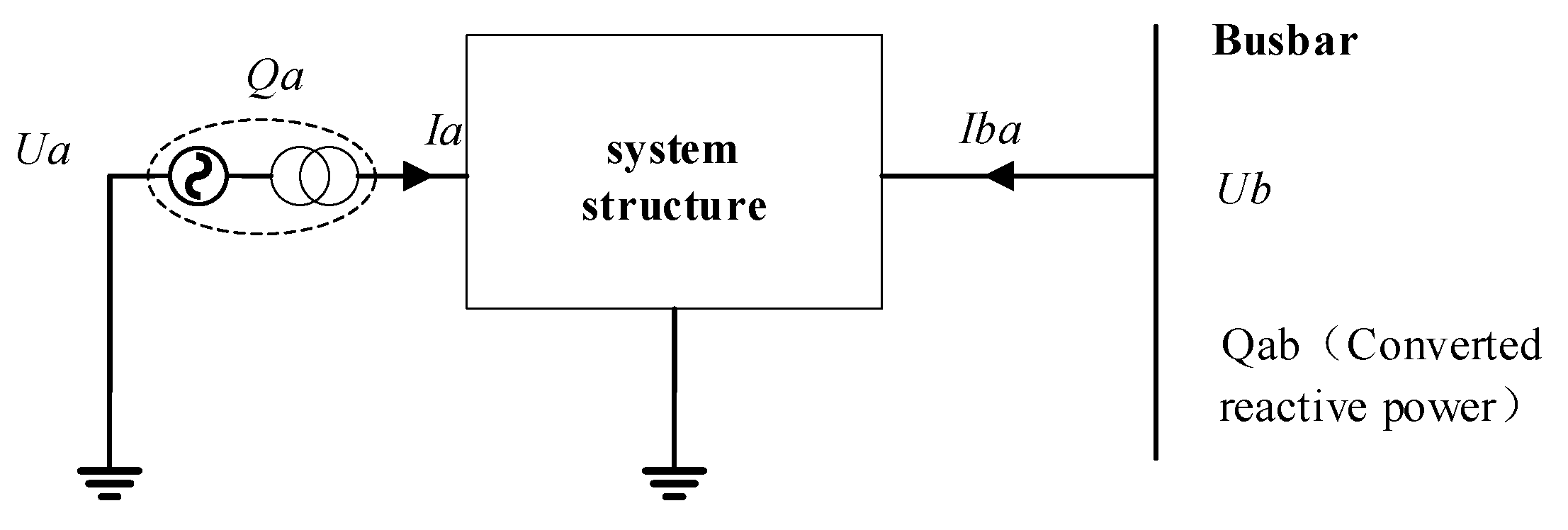
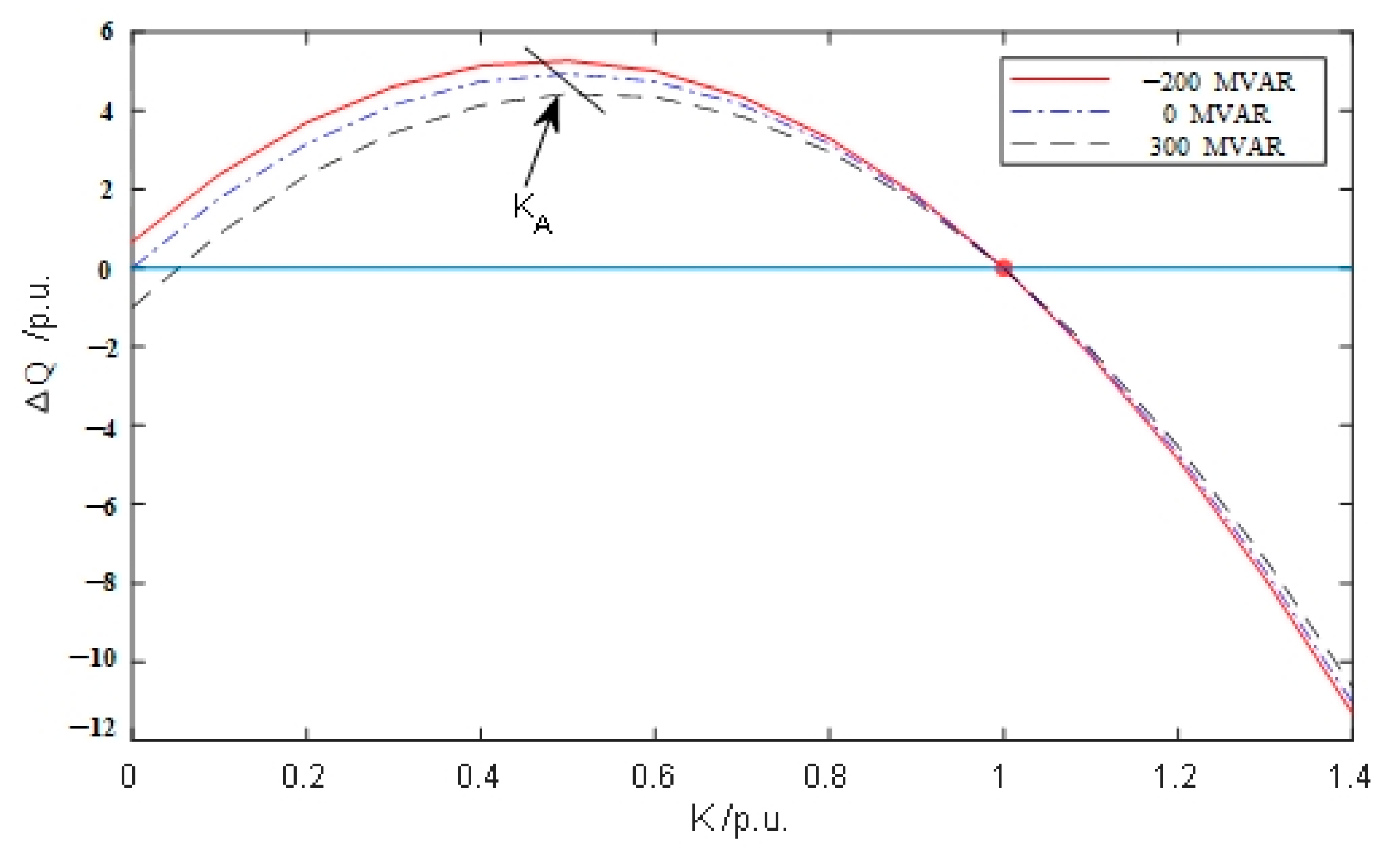
3.1. Reactive Power Conversion Factor Indicator

In response to the issues encountered in the operation of AC–DC hybrid power grids, dynamic reactive power compensation devices should be installed at converter stations and weak nodes in the AC system to raise busbar voltage and avoid DC commutation failures or even more severe system faults. To select units that can better fulfill their functions, a reactive power conversion factor between any two nodes is proposed.
First, based on the schematic diagram of reactive power support provided at any node as shown in Figure 3, the concept of the reactive power conversion factor indicator (RPCFI) is introduced.
Due to the different electrical distances between each point of the SC and the converter station bus, when calculating the voltage fluctuation amplitude of the converter station bus, the influence of line impedance needs to be fully considered. Based on the derivation of the short-circuit ratio, a method for converting the reactive power compensation capacity of a node to that of any other node is proposed. As shown in Figure 3, reactive power compensation is performed at node a, with the dashed area indicating the SC and their step-up transformers; point b represents the DC fault point. Node a is connected to SC with a capacity of Qa. First, consider Zab as the mutual impedance between nodes a and b, and Zbb as the self-impedance at node b. To derive the reactive power Qab after the conversion of Qa, the reactive power converted to point b should be calculated.
Q a b = U b I a b
When a current Ia is injected at node a, the equivalent voltage generated at the compensation point b by this current is calculated as follows:
U b a = I a Z a b
In Figure 3 of the simplified conversion network, the expression for the converted current Iab from injecting current Ia at node a to node b is given by the following:
I a b = U b a Z b b = I a Z a b Z b b
We obtain the converted reactive power Qab from (15) and (16) when the injected reactive power Qa at node a is converted to node b.
Q a b = U b I a b = U a I a Z a b Z b b = Q a Z a b Z b b
We introduce the reactive power conversion factor indicator λ as follows:
λ = Z a b Z b b
We transform the compensatory reactive power Qa from the remote location to the converter station to obtain the transformed compensatory capacity Qab, rewritten as Qab = λQa. Therefore, the voltage fluctuation of the converter station bus voltage with the remote reactive power injection is defined as follows:
Δ V a b = λ Q a S k = Z a b Q a Z b b S k
In the formula, Qa represents the reactive power output from the SC at any point a in the system; Sk denotes the short-circuit capacity of the busbar.

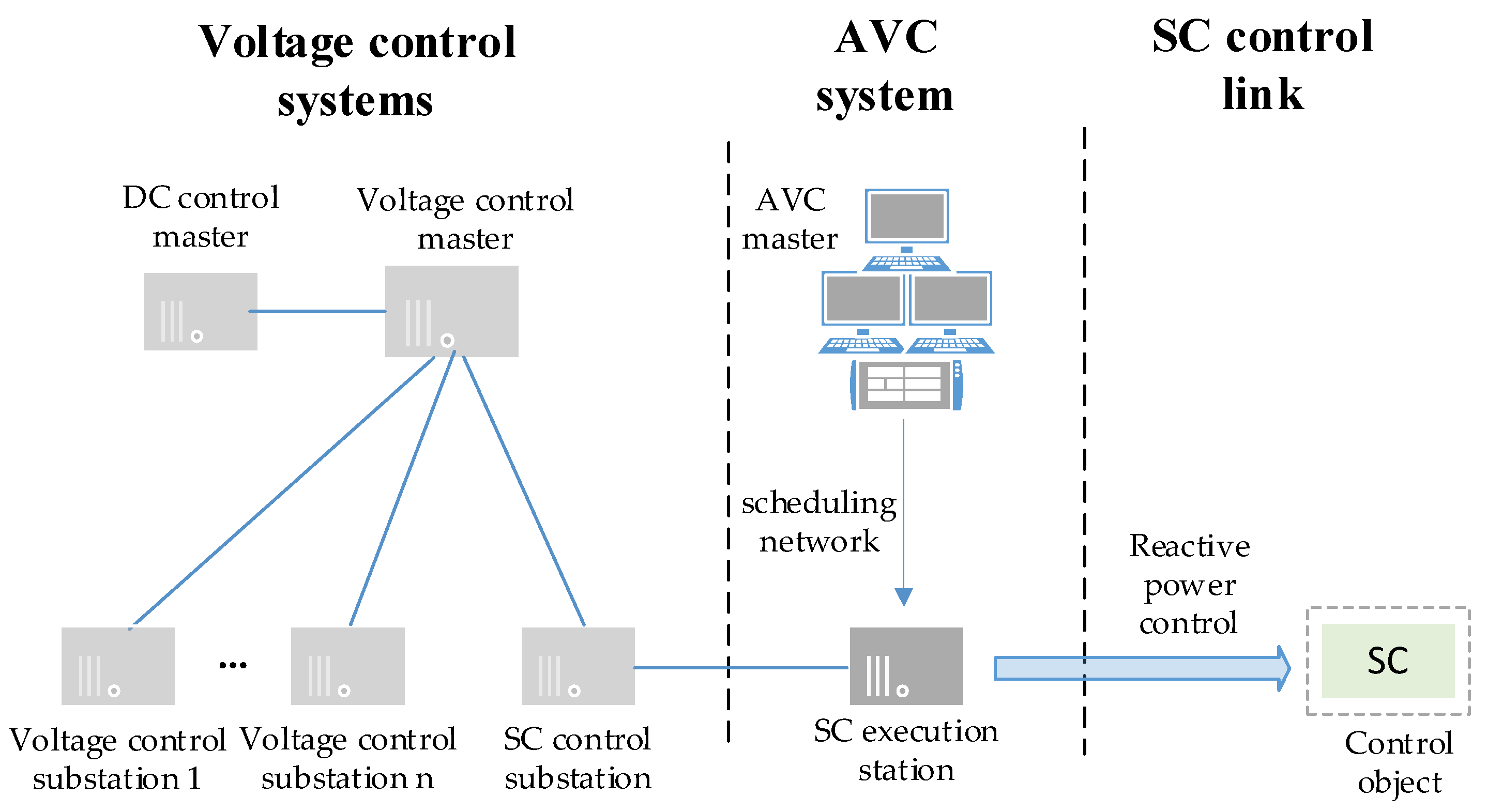
3.2. Design of System Control Architecture

The design of the reactive power optimization control system consists of three parts: the voltage control system, the AVC system, and the SC reactive power control system. The system aims to control the bus voltage of the converter station, monitoring it in real-time. When the voltage drops to a critical level, a voltage warning is sent to the voltage control system. The control center, based on the λ-filtered information of the synchronous condenser within the network, sends a control signal to the synchronous condenser control execution station. Finally, the execution station sends excitation adjustment instructions to the synchronous condenser to optimize key performance parameters and complete the reactive power optimization of the SC. The system structure is shown in Figure 4.

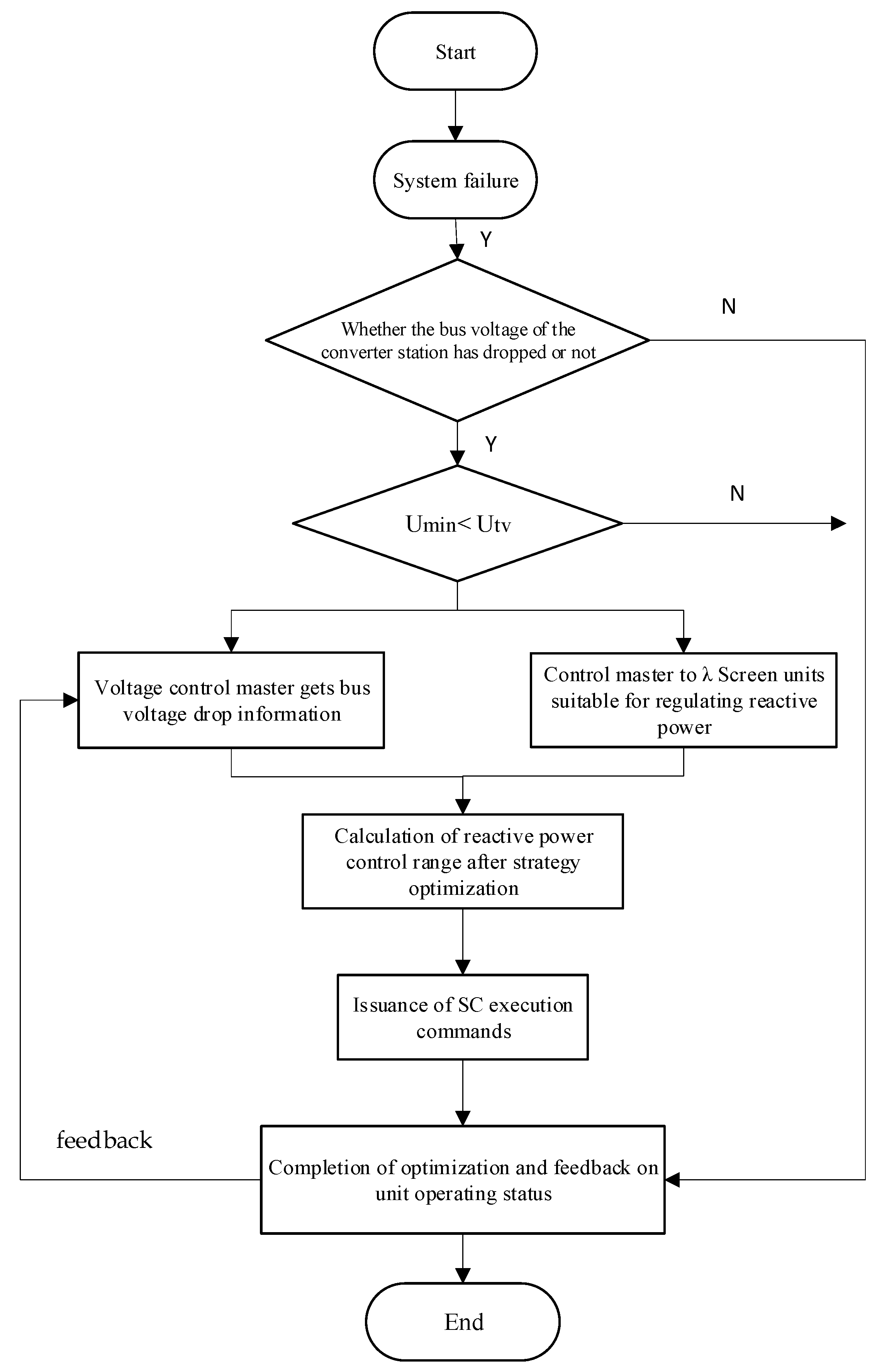
3.3. SC Reactive Power Optimization Strategy Based on Reactive Power Conversion Factor Indicator

Most commutation failures in direct current (DC) transmission systems occur in the inverters. To prevent commutation failures on the inverter side, it is essential first to understand the mechanisms of commutation failure in DC transmission systems. During normal operation, the AC system is symmetrical, and the rectifier-side DC commutation angle is calculated as follows:
γ = arccos ( T 2 I d X L U + cos β )
where T is the transformer conversion ratio, Id is the DC current, XL is the commutation reactance, β is the lead angle on the inverter side, and U is the effective value of the commutation bus line voltage. After a fault occurs, when the bus voltage drops, the shutdown of the inverter can be represented as the following:
c o s γ = I , d ( cos γ 0 + cos α ) I d cos α
Among them, Id′ represents the direct current after the voltage drop. After a decrease in the AC system voltage on the inverter side, in order to keep the commutation area equal, the commutation angle increases and the turn-off angle decreases. Typically, when the turn-off angle is less than seven electrical degrees, the commutation process cannot be completed properly. Therefore, the critical voltage value that causes commutation failure after a fault can be expressed as the following:
U t v = U L cos α + cos β cos α + cos γ 0
Utv is the critical voltage for three-phase fault commutation failure. UL is the DC bus voltage value. γ is the normal commutation angle of the converter. Based on the commutation failure principle, an SC reactive power compensation strategy based on the RPCFI is proposed: Based on the structure of the excitation control system and the electromagnetic equations of the motor, the expression for the reactive power output of the synchronous condenser as follows:
Q lim = Q c x _ S C max = U 2 X d K C S N , ( U > E 0 ) Q j x _ S C max = ( k f m 1 ) U 2 X d ( k f m 1 ) K C S N , ( U < E 0 )
Furthermore, the phase-shifting limits of the synchronous condenser, Qjx_SCmax and Qcx_SCmax, are obtained. Here, U represents the terminal voltage of the synchronous condenser, E0 is the terminal potential under normal operating conditions, Xd is the stator reactance of the synchronous condenser, KC is the short-circuit ratio of the synchronous condenser, SN is the rated capacity of the synchronous condenser, and kfm is the excitation multiple of the synchronous condenser.
If the minimum voltage drop at any bus after a fault obtained from the grid operation data in the project is Umin, then the transient reactive power support capability of any node SC should meet the following strategy:
0 < λ = Z a b Z b b 1 U min + λ Q S C min S k > U t v K f m 1 K C S N Q S C min K C S N
QSCmin is the minimum reactive compensation capacity required after the SC investment for any node. When the excitation control system or key performance parameters of the generator are adjusted so that the reactive power output of the synchronous condenser reaches exactly QSCmin, it can just avoid DC commutation failure and maintain system stability. The strategy flowchart is shown in Figure 5.
After the busbar signals from the converter station are sent to the voltage control system, the warning information of DC commutation failure is integrated and calculated by the main station to identify the SC units that need to be regulated. Subsequently, the SC control station sends reactive power control information to the execution station based on QSCmin. The execution station then adjusts the performance parameters of the SC units to modify the excitation voltage, ultimately completing the optimized control.
If QSCmin satisfies Qjx_SCmaxQSCminQcx_SCmax, then the optimized reference value for reactive power output is the actual calculated value of QSCmin; if not, the optimized reference value for reactive power output should approach Qlim = Qcx_SCmax (or Qlim = Qjx_SCmax).
A certain amount of dynamic reactive power reserve should be set on the optimized reference value of reactive power output QSCmin, ensuring that the final adjusted reactive power output of the SC is greater than the calculated value of QSCmin. This approach is aimed at addressing the peak reactive power demand caused by load variations and maintaining voltage stability.

4. Simulation Analysis Study

To analyze the proposed theoretical analysis, the ±800 kV Shanxi–Wuhan UHVDC receiving end Hubei power grid is used as an example. The basic operational background of the power grid is as follows: The total installed capacity of the unified dispatch within the Hubei power grid is 66,505 MW, of which thermal power accounts for 29,193 MW (43.9%) and hydropower accounts for 33,546 MW (50.4%). There are 37 substations at 500 kV (including 7 converter stations) connected to the 500 kV grid, with 56 main transformers and a total capacity of 52,183 MVA. The province has 140 AC and DC lines at 500 kV, with a total length of 12,329 km. Based on this operational background, the schematic diagram of the 500 kV partial power grid in Hubei is shown in Figure 6.

4.1. Optimization of Initial Reactive Power Output forSC

SC has infinite compensation capabilities, so during steady-state operation, synchronous condensers can be used for precise reactive power compensation. However, the initial reactive power of SC can affect its dynamic reactive power reserve. When the initial voltage is fixed, the relationship between the reactive power increment and the voltage variation degree K under the steady-state operating conditions of SC at −200, 0, and 300 Mvar is shown in Figure 7.
In the figure, KA represents the maximum transient reactive power increment. K represents the degree of voltage variation in the power grid. From the analysis in Figure 7, the following conclusions can be drawn for voltage decreases (K < 1) and increases (K > 1):
When the voltage decreases, the smaller the initial inductive reactive power (or the larger the capacitive reactive power), the greater the reactive power increment that can be provided. As the voltage drop increases, the maximum reactive power increment initially rises and then falls. The maximum reactive support can be provided at approximately 50% of the rated voltage. When the voltage rises, the smaller the initial inductive reactive power (or the larger the capacitive reactive power), the greater the reactive power increment that can be provided, following the same pattern as with voltage decreases. As the voltage increase becomes larger, the maximum reactive power increment will continue to rise.
Therefore, by adjusting the initial reactive power output of the SC, the rapid support performance of the phase shifter can be effectively improved.
Further, to study the support effect of initial reactive power on commutation failure, different sizes of impedance were connected to the AC busbar of the converter station to simulate AC grid faults at various distances from the converter station. The factors related to UHVDC commutation failure were obtained. The initial reactive power values used for calculation were −50 Mvar, 0 Mvar, 50 Mvar, and 100 Mvar, with the results shown in Table 1 below.
Analysis of the charts indicates that having a reactive power capability at the initial stage of the synchronous condenser is beneficial for preventing commutation failure at the receiving end of the power grid. When the initial reactive power output increases from 0 Mvar to 50 Mvar, the critical voltage for commutation failure changes by approximately 10 kV. Similarly, increasing the initial reactive power output from 50 Mvar to 100 Mvar also results in a change of about 10 kV in the commutation failure critical voltage. Therefore, it is recommended to adjust the operating strategy of the HVDC receiving end converter’s phase-shifting reactive power capability from the current 0 Mvar to a range between 0 and 80 Mvar. This adjustment can better support the HVDC commutation process while also ensuring the voltage stability of the grid.

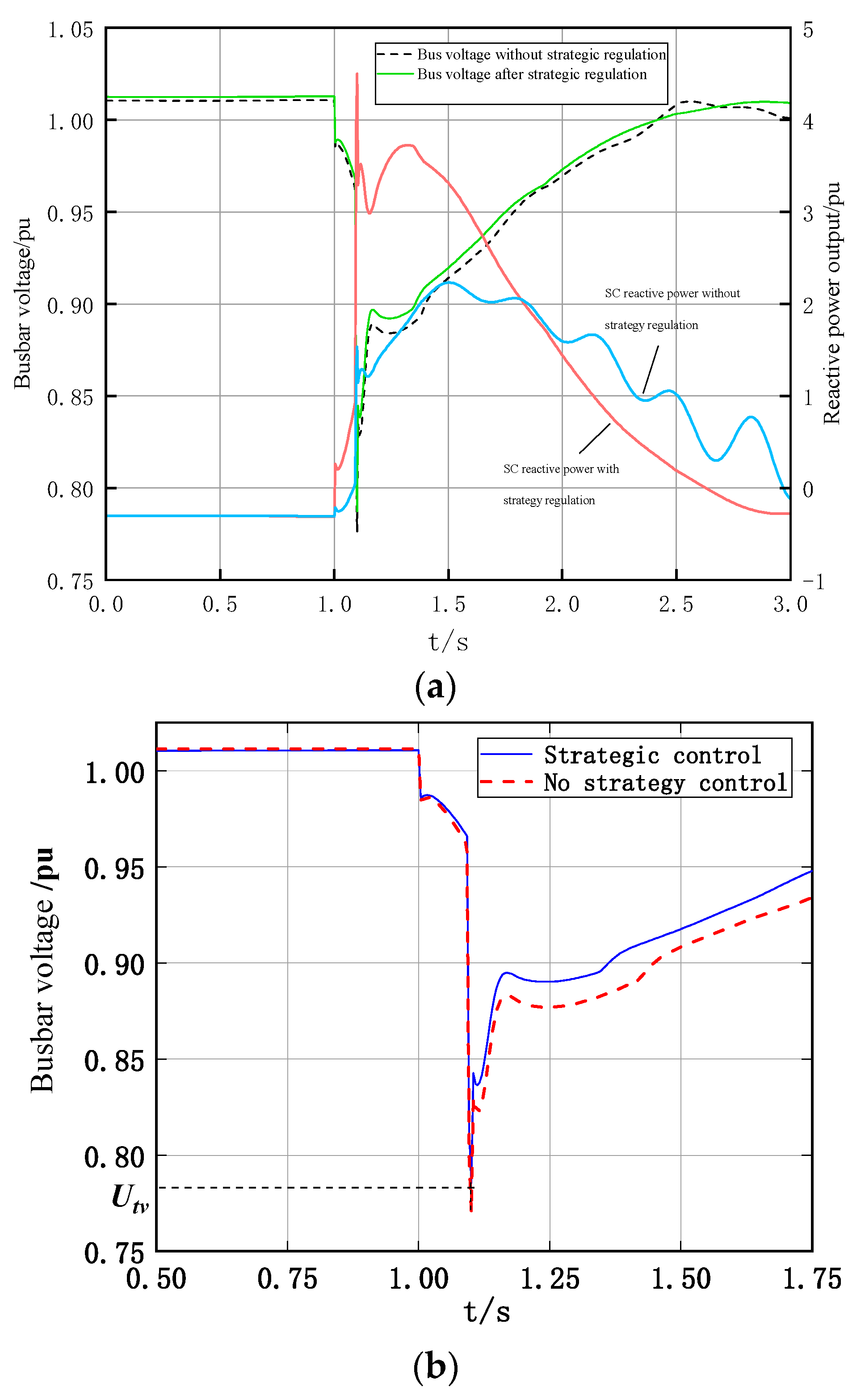
4.2. SC Reactive Power Optimization Strategy to Avoid DC System Failures

To verify whether the proposed SC reactive power coordination strategy can effectively prevent commutation failure and maintain system voltage stability, the voltage fluctuations at the converter station bus under different SC reactive power output conditions were compared during the transient process after a fault by adjusting key performance parameters of the unit.
For the Hubei power grid and its operating data shown in Figure 6, the fault simulation was set as a permanent three-phase short circuit, with the fault location at 2% from the double-line near point ② to the converter station. The unit parameters used for the simulation are as follows: the rated apparent power is 711.111 MVA; the rated active power is 640 MW; and the rated power factor is 0.9. The commutation failure critical voltage Utv calculated from actual grid operating data is 0.78 pu. The simulation test point is site ① in the grid structure diagram. Before any adjustments, the bus voltage drop after the fault at site ① was found to be Umin = 0.77035 pu based on operational data. To avoid commutation failure when SC is put into operation at site ①, the target desired SC lift voltage is approximately 0.01 pu. The transient reactive power output optimization reference value Qscmin calculated from (23) is 300 Mvar, satisfying Qjx_SCmaxQSCminQcx_SCmax. Hence, the reactive power output range for SC, according to the optimization strategy, is set from 300 to Qcx_SCmax.
To further validate the proposed strategy and whether the optimization reference range for reactive power output can reduce the risk of voltage instability, we first obtained a set of different SC reactive power response capabilities by setting a group of different key performance parameters for the direct axis of the units on the simulation platform, as shown in Figure 8.
The transient reactive power response capability of the synchronous condenser (SC) under different operating conditions is shown in Figure 8. Figure 8a–f represent a set of reactive power response characteristics exhibited by the SC with different direct-axis reactance parameters on the simulation platform. Analysis of the figure reveals that the direct axis reactance parameter can significantly influence the transient reactive power response capability of the SC. Moreover, the peak value of the transient reactive power output of the SC is inversely proportional to the direct axis reactance parameter. Therefore, when designing the synchronous condenser and modifying the unit, optimizing the key performance parameters of the SC can enhance its peak transient reactive power output and significantly increase the amplitude of reactive power output during dynamic processes. This can serve as the basis for the design of new generation units. Based on the different reactive power responses of the SC, the bus voltage fluctuations under conditions where Qsc meets the optimization strategy criteria and where it does not are simulated and calculated as shown in Figure 9.
From Figure 9, Figure 9a compares the reactive power response capability of the SC unit before and after the implementation of the control strategy, Figure 9b shows the details of the converter station bus voltage fluctuations before and after the strategy regulation. It can be observed that the bus voltage exhibits better post-fault recovery characteristics after optimizing the reactive power output of the synchronous condenser (SC). The voltage drop magnitude is significantly reduced. The reactive power support capability of the SC, after strategic regulation, results in the minimum bus voltage drop being higher than the critical voltage Utv for commutation failure. This prevents subsequent DC commutation failures. Additionally, the reactive power response curve of the phase modulator is smoother, indicating that the system has better stability. To further verify whether the reactive power optimization reference values can effectively prevent commutation failure and other instability risks, a simulation analysis was conducted on the bus voltage fluctuations under different transient reactive power response capabilities, as shown in Table 2.
The analysis of Table 2 reveals that for the reactive power support of DC systems provided by near-field SCs, a higher transient reactive response capability of the synchronous condenser (SC) results in better voltage support, leading to higher bus voltage during faults. However, when the transient reactive response capability of the SC post-fault fails to meet the optimized reactive power output reference value QSCmin, it causes the bus voltage to drop below the critical commutation failure voltage, posing a risk of grid instability. Implementing reactive power optimization strategies to limit reactive power output can effectively prevent subsequent DC commutation failures.
In summary, the SC reactive power coordination strategy based on λ and QSCmin provides guidance for optimizing the reactive power output of synchronous condensers and eliminating the risk of grid instability.

5. Conclusions

For the AC grid connected to multiple DC feeds, commutation failure can have severe consequences, potentially disrupting system balance and stability. Although extensive research has shown that synchronous condensers significantly help in maintaining system voltage stability and reducing the probability of DC commutation failure, their reactive power support capabilities are often not fully utilized. This paper offers improvement suggestions for both grid voltage support and commutation failure support for SC initial reactive power. Furthermore, a reactive power conversion factor between two nodes is proposed, and based on this, a reactive power optimization strategy for SC is presented that can effectively avoid DC commutation failure. Conclusions are as follows:
(1)
The large-capacity synchronous condenser has the effect of supporting low bus voltage. The occurrence of commutation failure on the receiving end of a DC system can be reduced with the application of a synchronous condenser.
(2)
When the terminal voltage changes (K < 1 or K > 1), the synchronous condenser can adjust the reactive power output flexibly immediately during the transient process. Additionally, adjusting the initial reactive power output of the SC to a reasonable range can effectively enhance the fast support capability of the SC, thereby improving system stability.
(3)
Based on the reactive power conversion factor and the QSCmin-based SC reactive power optimization strategy, the system can more accurately suppress subsequent DC commutation failures during faults by selecting suitable synchronous condensers and optimizing their reactive power output.
This provides a reference for unit design, key performance parameter control, and excitation control, enabling better management of reactive response capabilities and dynamic reactive power reserve planning, thereby reducing the probability of high-voltage DC continuous commutation failures and enhancing system stability.
Our future research will focus on optimizing the parameters of the excitation system and the synchronous condenser (SC) unit itself. These two components are critical in influencing the reactive power output characteristics of the SC. Optimizing the excitation system can lead to more precise control of the synchronous condenser, while a study of the key parameters of the SC unit can provide guidance for the retrofit of synchronous condensers in the context of new power system developments. Ultimately, this will enhance the economic efficiency and stability of system operations.

Author Contributions

Conceptualization, Z.T.; methodology, Z.T. and T.W.; software, Z.T. and R.C.; validation, Z.T. and R.C. and T.W.; formal analysis, Z.T.; investigation, Z.T. and D.C.; resources, Z.T. and D.C.; data curation, Z.T.; writing—original draft preparation, Z.T.; writing—review and editing, Z.T. and T.W.; visualization, Z.T.; supervision, D.C., R.C. and T.W.; project administration, T.W.; funding acquisition, T.W. and Z.T. All authors have read and agreed to the published version of the manuscript.

Funding

This research was funded by [National Natural Science Foundation of China] grant number [51677012].

Data Availability Statement

The original contributions presented in the study are included in the article, further inquiries can be directed to the corresponding author.

Conflicts of Interest

Authors Tao Wang, Defu Cai and Rusi Chen were employed by the Electric Power Research Institute, State Grid Hubei Electric Power Co., Ltd. The remaining authors declare that the research was conducted in the absence of any commercial or financial relationships that could be construed as a potential conflict of interest.

References

  1. Ma, Y.; Geng, G.; Jiang, Q.; Yan, R. Transient Stability Emergency Control for AC/DC Grids Considering Successive Commutation Failures. IET Gener. Trans. Distrib. 2022, 16, 1319–1333. [Google Scholar] [CrossRef]
  2. Abedin, T.; Lipu, M.S.H.; Hannan, M.A.; Ker, P.J.; Rahman, S.A.; Yaw, C.T.; Tiong, S.K.; Muttaqi, K.M. Dynamic Modeling of HVDC for Power System Stability Assessment: A Review, Issues, and Recommendations. Energies 2021, 14, 4829. [Google Scholar] [CrossRef]
  3. Dong, X.; Guan, E.; Jing, L.; Wang, H.; Mirsaeidi, S. Simulation and Analysis of Cascading Faults in Hybrid AC/DC Power Grids. Int. J. Electr. Power Energy Syst. 2020, 115, 105492. [Google Scholar] [CrossRef]
  4. Zhang, Z.; Zeng, Y.; Ma, J.; Qin, C.; Meng, D.; Chen, Q.; Chen, W. Online Correction of the Transient Voltage Security Region Boundary Based on Load Parameter Variations in Power Systems. Front. Energy Res. 2023, 11, 1233515. [Google Scholar] [CrossRef]
  5. Li, X.; Li, F.; Chen, S.; Li, Y.; Zou, Q.; Wu, Z.; Lin, S. An Improved Commutation Prediction Algorithm to Mitigate Commutation Failure in High Voltage Direct Current. Energies 2017, 10, 1481. [Google Scholar] [CrossRef]
  6. Samaan, S.; Momeni, M.; Knittel, M.; Murglat, M.; Moser, A. Multi-Criteria Based Steady-State and Dynamic Reactive Power Planning for Transmission Systems. Electr. Power Syst. Res. 2022, 209, 107929. [Google Scholar] [CrossRef]
  7. Watson, N.R.; Watson, J.D. An Overview of HVDC Technology. Energies 2020, 13, 4342. [Google Scholar] [CrossRef]
  8. Jing, B.; Ling, Y.; Wang, D.; Zhu, E.; Han, X. Analysis of Transient Electromagnetic Force on End Windings of 300 Mvar Synchronous Condenser during Dynamic Reactive Power Compensation Process. Int. J. Electr. Power Energy Syst. 2024, 155, 109538. [Google Scholar] [CrossRef]
  9. Li, C.; Gu, W.; Xia, C.; Li, H.; He, F. Analysis on Mechanism and Characteristic of Vibration Fault on New Large Capacity Synchronous Condenser. J. Phys. Conf. Ser. 2024, 2731, 012002. [Google Scholar] [CrossRef]
  10. Soleimani, H.; Habibi, D.; Ghahramani, M.; Aziz, A. Strengthening Power Systems for Net Zero: A Review of the Role of Synchronous Condensers and Emerging Challenges. Energies 2024, 17, 3291. [Google Scholar] [CrossRef]
  11. Wang, Z.; Xiao, F. Calculation Method of DC Limit Power Considering Influence of New-Generation Synchronous Condensers. J. Phys. Conf. Ser. 2021, 2022, 012004. [Google Scholar] [CrossRef]
  12. Guo, Z.; Hao, L.; Wu, J. Application of the New Generation Large Capacity Synchronous Condenser in HVDC System. IOP Conf. Ser. Earth Environ. Sci. 2019, 342, 012007. [Google Scholar] [CrossRef]
  13. Mo, J.; Yan, W.; Chen, X.; Zhang, Z. Parameter Setting Method of Coordinated Control between Synchronous Condenser and DC System Based on Dynamic Reactive Power Optimization. IET Gener. Transm. Distrib. 2022, 16, 2298–2308. [Google Scholar] [CrossRef]
  14. Bao, L.; Fan, L.; Miao, Z. Maximizing Synchronous Condensers’ Capability to Stabilize Inverter-Based-Resource-Penetrated Grids. IEEE Trans. Energy Convers. 2024, 1–13. [Google Scholar] [CrossRef]
  15. Xie, H.; Huang, T.; Zhao, W.; Sun, K.; Lin, D.; Huang, Q.; Yang, M. Modeling of Large Capacity Condenser Based on Electromagnetic Transient Simulation and Its Impacts on East China Power Grid. IOP Conf. Ser. Earth Environ. Sci. 2022, 983, 012033. [Google Scholar] [CrossRef]
  16. Jiang, M.; Ma, H.; Zhu, H.; Zhang, Y. Fault Indicator Based on Stator Current under Early Stage SISC in Synchronous Condensers. Eng. Fail. Anal. 2023, 145, 107044. [Google Scholar] [CrossRef]
  17. Qu, G.; Yuan, H. Automatic Voltage Control of Large-Scale Synchronous Condensers in UHV-DC Converter Station. E3S Web Conf. 2021, 236, 01001. [Google Scholar] [CrossRef]
  18. Wu, M.; Wang, T.; Li, P.; Wang, Y.; Cai, Y.; Zhou, J.; Huang, W. Improvement of Dynamic Reactive Power Characteristics of New-Type Condenser by Excitation Parameters. J. Phys. Conf. Ser. 2022, 2276, 012039. [Google Scholar] [CrossRef]
  19. De Marco, F.; Gómez, J.; Bolz, V.; Fernández, F. Identifying Optimal Combinations of Synchronous Condensers for Minimum Grid Strength Compliance. Int. J. Electr. Power Energy Syst. 2024, 156, 109756. [Google Scholar] [CrossRef]
  20. Li, H.; Wang, Z.; Liu, P.; Wang, W.; Zhou, T.; Mao, W.; Liu, H.; Wang, X. Dynamic Reactive Power Coordination Control Method for UHVDC Converter Station. IOP Conf. Ser. Mater. Sci. Eng. 2019, 631, 042043. [Google Scholar] [CrossRef]
  21. Mo, J.; Yan, W.; Ren, Z.; Xiao, F.; Wang, T. Dynamic Reactive Power Optimisation of UHVDC Converter Station Considering Coordination of Synchronous Condenser and System Filtering Requirements. IET Gener. Transm. Distrib. 2020, 14, 4563–4570. [Google Scholar] [CrossRef]
  22. Zhang, J.; Hu, R.; Chen, P.; Sun, M.; Cheng, L.; Li, P. Research on Voltage Coordinated and Stability Control of Condensers Based on Reactive Power Replacement. J. Phys. Conf. Ser. 2024, 2800, 012032. [Google Scholar] [CrossRef]
  23. Hadavi, S.; Saunderson, J.; Mehrizi-Sani, A.; Bahrani, B. A Planning Method for Synchronous Condensers in Weak Grids Using Semi-Definite Optimization. IEEE Trans. Power Syst. 2023, 38, 1632–1641. [Google Scholar] [CrossRef]
  24. Jiménez, R.P.; Platero, C.A.; Sánchez, M.E.; Barneto, E.R. Synchronous Condenser for European Grid Code Compliance: A Case Study of a PV Power Plant in Spain. IEEE Access 2023, 11, 54713–54723. [Google Scholar] [CrossRef]
  25. Jiang, M.; Ma, H.; Zhang, Y.; Chen, X.; Zhao, X. Reactive Power Characteristics and Vibration Properties under SISC in Synchronous Condensers. Int. J. Electr. Power Energy Syst. 2021, 133, 107318. [Google Scholar] [CrossRef]
  26. Dimitropoulos, D.; Bakhshizadeh, M.K.; Kocewiak, L.; Wang, X.; Blaabjerg, F. Impact of Synchronous Condensers’ Ratings on Mitigating Subsynchronous Oscillations in Wind Farms. Energies 2024, 17, 1730. [Google Scholar] [CrossRef]
Figure 1. Excitation current regulation V-curve.
Energies 17 04294 g001
Figure 2. Extra-high voltage converter stations and their AC grid equivalent circuits.
Energies 17 04294 g002
Figure 3. Schematic diagram of reactive power capacity conversion.
Energies 17 04294 g003
Figure 4. Structure of reactive power optimization control system.
Energies 17 04294 g004
Figure 5. SC reactive power optimization flowchart.
Energies 17 04294 g005
Figure 6. Structure of the 500 kV grid.
Energies 17 04294 g006
Figure 7. Transient reactive power increment with different initial reactive power.
Energies 17 04294 g007
Figure 8. SC transient reactive power responsiveness under different key performance parameters.
Energies 17 04294 g008
Figure 9. Comparison of operating conditions before and after strategic regulation.
Energies 17 04294 g009
Table 1. Effect of SC initial reactive power output on critical voltage for phase change failure.
Grounding
Inductance (H)
SC Are Not
Involved
Initial Reactive Power Output of the SC
−50 Mvar0 Mvar50 Mvar100 Mvar
Converter Station Bus Voltage (p.u.)Transient
Reactive Power Peak Value (Mvar)
Converter Station Bus Voltage (p.u.)Transient
Reactive Power Peak Value (Mvar)
Converter Station Bus Voltage (p.u.)Transient
Reactive Power Peak Value (Mvar)
Converter Station Bus Voltage (p.u.)Transient
Reactive Power Peak Value (Mvar)
0.12———— 0.737243—— ——
0.130.751—— 0.761 —— 0.744302
0.140.729—— —— —— 0.757293
0.150.7740.782153.55—— 0.7382770.771289
0.16——0.788153.9—— 0.777245——
0.170.7690.791142.3—— 0.787 ——
0.180.7930.794138.80.7981820.788233——
0.190.791—— 0.797180—— ——
0.200.796—— —— —— ——
Table 2. Simulation results of QSCmin-based suppression of phase change failure.
The Transient
Reactive Power Response
Capability of SC/p.u.
Key
Performance Parameters/p.u.
Converter
Station Bus Voltage/p.u.
Voltage-Supported Amplitude/p.u.The Occurrence of Subsequent
Commutation
Failure
5.0360.0650.785360.01501N
3.5330.150.782600.01225N
3.0100.20.780950.01060N
2.5840.250.778650.00830Y
2.0110.350.776730.00638Y
1.5340.480.775060.00471Y
Disclaimer/Publisher’s Note: The statements, opinions and data contained in all publications are solely those of the individual author(s) and contributor(s) and not of MDPI and/or the editor(s). MDPI and/or the editor(s) disclaim responsibility for any injury to people or property resulting from any ideas, methods, instructions or products referred to in the content.

