1. Introduction
Photovoltaic (PV) systems are pivotal in transitioning towards a sustainable energy matrix and reducing dependency on fossil fuels. These systems are considered one of the most promising renewable energy sources due to their noiseless operation, cleanliness, ease of installation, inexhaustibility, and pollution-free functioning [
1]. Currently, the penetration of grid-connected PV systems in low voltage distribution networks (LVDNs) is growing extensively and is expected to increase rapidly in the future. This growth is driven not only by the aforementioned benefits, but also by decreasing prices, safer operation with lower operational costs, and supportive government policies [
2].
PV systems usually have relatively arbitrary phase connections in LVDNs, where it is common to find three different types of PV inverter connections: three-phase, two-phase, and single-phase. Combined with the intermittent nature of these systems, this presents a challenge in terms of power quality issues. As more PV systems are integrated into the LVDNs, uncertainties regarding the system unbalance increase.
Another critical issue in LVDNs is the massive penetration of single-phase loads, which are often connected in a disordered manner throughout the network. This can lead to severe current unbalances, and non-symmetrical power flow that can increase voltage unbalances and cause significant overvoltage issues. This negatively affects the efficiency of the distribution network and increases energy losses and instability. These unbalances can also lead to technical problems such as failures of sensitive loads, overheating of electrical equipment, and potential long-term damage to equipment [
3]. Additionally, the widespread use of low-power factor loads and power electronics-based equipment in LVDNs adversely affects power quality by injecting distorted currents into the grid and demanding significant amounts of reactive power [
4].
Some solutions to counteract these problems include re-phasing loads to reduce voltage unbalances. This involves using additional switches to transfer loads from the overloaded phases to other phases and incorporating extra meters to provide the necessary measurements [
3]. Another solution is the use of traditional passive filters, which employ passive components such as inductors and capacitors to compensate for reactive power and mitigate specific harmonics. However, they can cause resonance problems in the grid and do not address the unbalance problem. One of the most effective solutions involves employing active power filters (APFs) or hybrid active power filters (HAPFs), offering flexibility and dynamic responses to disturbances. These devices, based on power electronics converters, can be controlled to mitigate unbalances, compensate for harmonics, and correct the power factor in LVDNs, among other functionalities [
4,
5]. However, implementing this solution requires additional components, thus raising costs.
In recent years, there has been an increase in the installation of PV systems near the loads. Furthermore, the topologies of power inverters in shunt APFs and their control systems are similar to those employed in grid-connected PV systems. These factors have created the opportunity to incorporate ancillary functions into PV inverters to enhance power quality and stability in LVDNs. PV systems typically operate below their rated capacity due to the intermittent nature of the energy source. There is minimal or no active power production for extended periods, particularly at nighttime. Consequently, the portion of the rated power not used for active power injection can be utilized for other functionalities. Some active filtering functionalities that can be added to PV inverters include harmonic mitigation, reactive power compensation, and load balancing [
6]. Moreover, other ancillary services are becoming essential in modern PV inverters, such as fault ride through (FRT), voltage regulation, and frequency support through active power curtailment, among others [
7,
8]. Accordingly, the next generation of PV inverters is expected to be more flexible and intelligent, including auxiliary services to help improve service quality.
A PV inverter that incorporates active power filtering functionalities is called a multi-functional PV inverter. Typically, the control structure of the PV inverter is modified to include the measurement of load currents and adjust the reference currents according to established compensation objectives, enabling load compensation capabilities [
6]. With these functionalities, additional APFs or other solutions may no longer be necessary for LVDNs, resulting in more cost-effective PV systems [
7,
9].
In the literature, several reported studies have proposed strategies for the control of multi-functional PV inverters. A very common approach is the development of control algorithms in the time domain based on electric power definitions. For instance, authors in [
10] propose a PV-APF controller for three-phase three-wire inverters based on the widely used
instantaneous power theory proposed by H. Akagi [
11]. This strategy mitigates harmonic currents and reactive power compensation and simultaneously injects the maximum power generated by the PV units. It also offers flexible operation modes for the PV-APF combination. Two similar approaches are presented in [
12,
13] for three-phase three-wire PV systems. Authors in [
12] propose a control algorithm for PV systems without DC/DC converters based on an extended instantaneous real and imaginary power method. Also, in [
13], an algorithm based on the generalized instantaneous reactive power theory is presented. These two works allow for the incorporation of power factor correction, load balancing, and current harmonic mitigation functionalities into the PV inverter. Another control strategy based on the definition of electrical powers is presented in [
6]. This work proposes a signal generation algorithm based on Fryze’s theory and an adaptive Butterworth–Kalman filter to include load compensation functions (power factor correction, current harmonics mitigation, and load balancing) to three-phase four-wire PV inverters under distorted and unbalanced grid voltages.
Other approaches for controlling multi-functional PV inverters involve estimating the fundamental component or specific harmonics of the load current. The estimated signals are then used to determine the reference currents required for the PV inverter to incorporate load compensation capabilities. For instance, in [
14], an adaptive generalized maximum Versoria criterion (AGMVC)-based control technique is developed for three-phase three-wire PV systems. This technique extracts the fundamental component of the non-linear load current. The resulting system allows active power transfer, harmonic mitigation, and load balancing. It also offers low steady-state mean square error and lower computational complexity. In [
15], a technique based on a second-order sequence filter is proposed to estimate the fundamental positive sequence component of distorted and unbalanced load currents with reduced mathematical computations. This estimation is then used to determine the reference signals for operating a universal active power filter integrated with a photovoltaic array (UAPF-PV) in three-phase three-wire systems. The resulting UAPF-PV system protects sensitive loads from PCC voltage dip/rise, compensating current harmonics and unbalances. Similarly, authors in [
2] use an adaptive notch filter control algorithm to estimate the average power-consuming component of the load current, which is then used to calculate the reference currents for a three-phase three-wire multi-functional PV inverter. This strategy includes reactive power compensation, harmonic current elimination, and load balancing functionalities for the PV inverter. Additionally, the proposal in [
16] presents a hybrid control scheme for multi-functional PV inverters based on a multiple second-order generalized integrator frequency-locked loop (MSOGI-FLL) and a multiple complex coefficient filter (MCCF)-based PLL. The MSOGI-FLL extracts the fundamental constituents (FCs) from the non-linear load currents, while the MCCF separates the FCs from polluted grid voltages. The resulting control scheme allows current and voltage harmonics mitigation, better DC offset rejection, and grid synchronization in three-phase three-wire systems.
Although the previous strategies achieve the established compensation objectives, they do not consider the nominal capacity of the inverter in their control schemes. As a result, the injected current could exceed the nominal values supported by this device. Furthermore, some studies do not prioritize the injection of the active power generated by the PV units over the load compensation functionalities. The power required to perform ancillary functions may exceed the capacity of the multi-functional PV inverter. Additionally, the connection of loads at the point of common coupling (PCC) is generally done arbitrarily. Therefore, it is essential to limit the capacity to perform load compensation functionalities in terms of the maximum current supported by the system to preserve the integrity of the components [
17].
One of the most straightforward techniques to limit the peak current injected by a multi-functional PV inverter is conventional saturation (CS) [
18]. In this technique, the reference current is directly limited using a saturation block, which restricts the signals to the upper and lower saturation values. This action generates unwanted low-order harmonics in the injected currents, deteriorating the signal quality. To improve this drawback, dynamic saturation (DS) techniques have been proposed. In these techniques, the current component required to perform the compensation functionalities is proportionally reduced using an attenuation factor (a factor less than unity), prioritizing active power injection and ensuring that the peak value of the reference current does not exceed the inverter rated capacity. In this case, the reference currents are not cut, and unwanted low-order harmonics are not generated. Authors in [
18] propose two DS techniques, one based on an open-loop algorithm and the other on a closed-loop anti-windup PI controller. However, these two techniques are proposed for single-phase inverters. In [
19], an extension of the anti-windup PI control-based DS technique presented in [
18] is proposed to be applied in three-phase three-wire multi-functional PV inverters. Although this technique limits the injected current according to the inverter’s rated capacity under load unbalance, it lacks flexibility. Consequently, the compensation functionalities cannot be prioritized according to defined objectives. Similarly, authors in [
17] propose a control scheme to limit the compensation current prioritizing active power injection in three-phase three-wire multi-functional PV inverters. However, the proposed scheme only considers current harmonic mitigation as an auxiliary service, so it does not deal with load unbalance compensation. Two similar approaches are also presented in [
20,
21] for three-phase three-wire multi-functional PV inverters. These works propose power management strategies that give priority to active power generation, then reactive power compensation, and finally current harmonic mitigation functionalities. Although these strategies prioritize specific compensation objectives, their performance under unbalanced load conditions is not analyzed or considered.
In [
7], a flexible power control strategy is proposed for single-phase PV inverters. The strategy is based on the single-phase
theory, which is an adaptation of the classical
instantaneous power theory. The strategy allows for the configuration of the PV inverter in different operating modes. One of these modes corresponds to the VAR operation, which includes reactive power compensation functionalities for the PV inverter. The proposed strategy limits the maximum reactive power to be delivered according to the nominal apparent power capacity of the inverter. However, this strategy is designed for single-phase inverters and, therefore, does not consider load balancing functionalities. In addition, authors in [
22] analyze four techniques for limiting the compensation currents in multi-functional PV inverters. In the same way, these strategies are only applied to single-phase inverters, so load balancing functionalities are not considered.
It is worth mentioning that the inclusion of load balancing capabilities in three-phase PV inverters leads to unbalanced currents flowing through the AC side of the inverter, which is required to perform the compensation functionalities. Consequently, the injected currents may have different amplitudes for the three phases. Additionally, the load compensation requirements change dynamically depending on the loads’ random connection and technical characteristics.
This paper proposes a flexible control strategy for three-phase three-wire multi-functional PV inverters, considering load balancing functionalities and the inverter rated capacity. Based on the instantaneous power definitions established by the
theory in [
11], a flexible strategy is proposed by incorporating two control parameters whose variation results in different load compensation capabilities. These parameters can be adapted dynamically according to both the portion of the inverter rated capacity not used for active power injection and the load compensation requirements. Likewise, the definition of the control parameters allows for prioritizing the compensation objectives. Furthermore, a control algorithm is proposed to limit the reference signals, ensuring that the inverter’s nominal current is not exceeded. This algorithm also follows a specific priority scheme. In this scheme, the highest priority is given to the injection of active power produced by the PV units over load compensation functionalities. Then, priority is given to reactive power compensation, and finally, load balancing functionalities are performed. This article does not focus on harmonic current compensation.
The rest of this article is structured as follows:
Section 2 provides a description of the multi-functional PV inverter configuration and some technical details about its components. The proposed flexible control strategy is presented in
Section 3. This section also describes the proposed control algorithm to both limit the phase current amplitudes and prioritize compensation objectives. This algorithm safely manages the injected currents in unbalanced load situations. Details of the experimental setup and results of experimental tests for the proposed algorithms are presented in
Section 4. Results verify the excellent performance of the proposals under various operational conditions. Finally,
Section 5 sets out the conclusions and main results of this paper.
3. Flexible Control Strategy for Multi-Functional PV Inverters
The development of a flexible control strategy for PV inverters with load compensation capabilities is discussed in this section. The flexible operation of the control strategy is achieved through two control parameters whose variation results in different load compensation capabilities. These parameters can be adapted dynamically according to the active power generated by the PV units, the load compensation objectives, and the inverter’s rated capacity.
Additionally, this section details the proposed control algorithm for limiting the reference currents, ensuring the inverter operates within safe limits. This algorithm enables the prioritization of compensation objectives by adjusting the two control parameters of the proposed flexible strategy. The inverter control algorithm establishes a compensation priority scheme according to the portion of the inverter’s rated capacity not utilized for active power injection.
Based on the above, the next section presents the control objectives considered by the proposed strategy, the reference signal generation strategy, and the proposed inverter control algorithm.
3.1. Control Objectives
The proposed strategy considers the following objectives:
Active power delivery: injection of the active power generated by PV units. This functionality should be prioritized over load compensation capabilities.
Reactive power compensation: improvement of the power factor at the PCC by compensating for the reactive power consumed by the load current at the fundamental frequency. This functionality reduces the RMS values of the grid currents and power losses in the distribution system.
Unbalanced load compensation: mitigation of unbalanced load currents, reducing the non-symmetrical power flow across the three phases.
Current limitation: the reference current amplitudes must be limited to ensure the inverter’s nominal current is not exceeded. Operating the inverter within its rated capacity is essential to prevent damage and extend its lifespan.
Prioritization of inverter functionalities: a flexible operation of the inverter is desired to allow for the prioritization of its functionalities.
Injection of sinusoidal currents: the injected currents should be as sinusoidal as possible at the fundamental grid frequency, thereby reducing harmonic distortion and complying with power quality requirements.
3.2. Reference Current Generation
Applying Clarke’s transformation in a three-phase three-wire system [
11], the phase voltages at the PCC, the injected currents, and the fundamental component of the load currents (denoted in
Figure 1 as the instantaneous vectors
,
, and
, respectively) can be expressed in the
stationary reference frame as a function of their positive- and negative-sequence components according to Equations (
1), (
2), and (
3), respectively.
where the superscripts + and − denote the positive- and negative-sequence components, respectively;
,
and
,
are the amplitudes and phase angles of the positive- and negative-sequence components of the phase voltages at the PCC, respectively;
,
and
,
are the amplitudes and phase angles of the positive- and negative-sequence components of the injected currents, respectively;
,
and
,
are the amplitudes and phase angles of the positive- and negative-sequence components of the load currents at the fundamental frequency, respectively; and
is the grid frequency.
According to the
theory proposed by H. Akagi [
11] for three-phase systems without a neutral conductor, the instantaneous active power (
p) and the instantaneous reactive power (
q) delivered by the inverter to the grid are defined as follows:
Considering the symmetrical components decomposition for the voltages at the PCC and the injected currents shown in Equations (
1) and (
2), respectively, the instantaneous active and reactive powers can be expressed as:
These two instantaneous powers can be also decomposed into two components, a constant and an oscillatory part:
where
and
represent the average and oscillating terms of the instantaneous active power, respectively, whereas
and
are the average and oscillating parts of the instantaneous reactive power, respectively. The average term
corresponds to the average active power injected by the PV inverter.
The average and oscillating terms of the instantaneous active and reactive powers can be expressed as a function of the positive- and negative-sequence components of the phase voltages at the PCC and the injected currents as follows:
As seen in Equations (
10)–(
13), the average terms,
and
, are the result of the interaction between symmetrical components of the same sequence, whereas the oscillating terms,
and
, are produced by interactions between symmetrical components of different sequence.
Expressing Equations (
10)–(
13) in matrix notation results in:
Solving the system presented in Equation (
14) and neglecting the negative sequence component of the voltage in the PCC, the positive- and negative-sequence components of the injected currents in the
reference frame are set as a function of the voltage in the PCC and the average and oscillating terms of the instantaneous active and reactive powers:
The expression presented in Equation (
15) corresponds to a generalized approach to calculate the reference currents for the multi-functional PV inverter. Based on (
15), several reference currents can be derived depending on specific control objectives.
Considering the control objectives established in this work, an expression is proposed based on this generalized expression. The proposed strategy aims to provide flexibility in prioritizing the functionalities of the PV inverter and dynamically limiting the compensation capabilities according to the portion of the inverter’s rated capacity not utilized for active power injection. For these purposes, the control parameters
and
are introduced, resulting in the proposed expressions (
16) and (
17) used to calculate the reference currents. The control parameters are positive real numbers whose values can fluctuate between 0 and 1. The parameter
allows for dynamic adjustment of the reactive power compensation capability, while
is used to adjust the load balancing capability.
where:
As seen in Equations (
16)–(
21), the references for the average and oscillating terms of the instantaneous active and reactive powers for the multi-functional PV inverter are set as:
The average active power () corresponds to the addition of the active power generated by the PV units () and the active power required to regulate the voltage at the DC bus ().
The average term of q is equal to the average term of the instantaneous reactive power demanded by the load (). This term is also multiplied by the control parameter , whose value can fluctuate between 0 and 1, allowing dynamic adjustment of the reactive power compensation capability. By reducing the value of , the amount of reactive power delivered by the PV inverter to compensate for the reactive power consumed by the load current at the fundamental frequency is reduced.
The oscillating terms of
p and
q are equal to the oscillating terms of the instantaneous active and reactive powers demanded by the load,
and
, respectively. These two oscillating terms are also multiplied by the control parameter
, whose value can fluctuate between 0 and 1, allowing it to dynamically adjust the load balancing capability. As seen in Equations (
16) and (
17), both
and
are multiplied by the same parameter
, which means that these two components must be reduced in the same proportion. This is required to ensure that the currents injected into the grid are not distorted and that the load unbalance compensation objective is met.
As a result, the variation of the control parameters and produces different load compensation capabilities and it allows for the prioritization of compensation objectives.
3.3. Inverter Control Algorithm
Incorporating load compensation capabilities into PV inverters can exceed the safety limits of the inverter current. To prevent this situation, the load compensation capabilities must be limited to ensure the inverter’s nominal current is not overpassed.
In this work, a control algorithm is proposed to prioritize compensation objectives while ensuring that phase current amplitudes remain within safe limits. This is achieved by adjusting the two control parameters and . The algorithm establishes the following priority scheme:
Priority 1: The highest priority is given to the injection of average active power () over load compensation functionalities.
Priority 2: The second priority is given to the reactive power compensation, meaning the injection of the average part of the instantaneous reactive power demanded by the load ().
Priority 3: The last priority is the load balancing functionality, that is, the compensation of the oscillating terms and .
For this prioritization, three thresholds are defined for the injected currents, as specified in Equations (
22)–(
24). The threshold
corresponds to the amplitude of the inverter phase current required to inject the total average active power
(Priority 1). The threshold
considers the amplitude of the inverter phase current required to inject
plus the total average part of the instantaneous reactive power demanded by the load (
), which corresponds to Priority 1 and Priority 2, respectively. Finally, the threshold
corresponds to the maximum amplitude among the three inverter phase currents required for the inclusion of all three functionalities: the injection of
,
, and the total oscillating terms
and
(Priority 1, Priority 2, and Priority 3, respectively).
In Equation (
24),
is calculated for the phase current with the highest amplitude, as the inverter phase currents are unbalanced. For this, the variable
is determined from expression (
25).
The discrepancy between the angles
can be calculated as defined in Equation (
26) [
26].
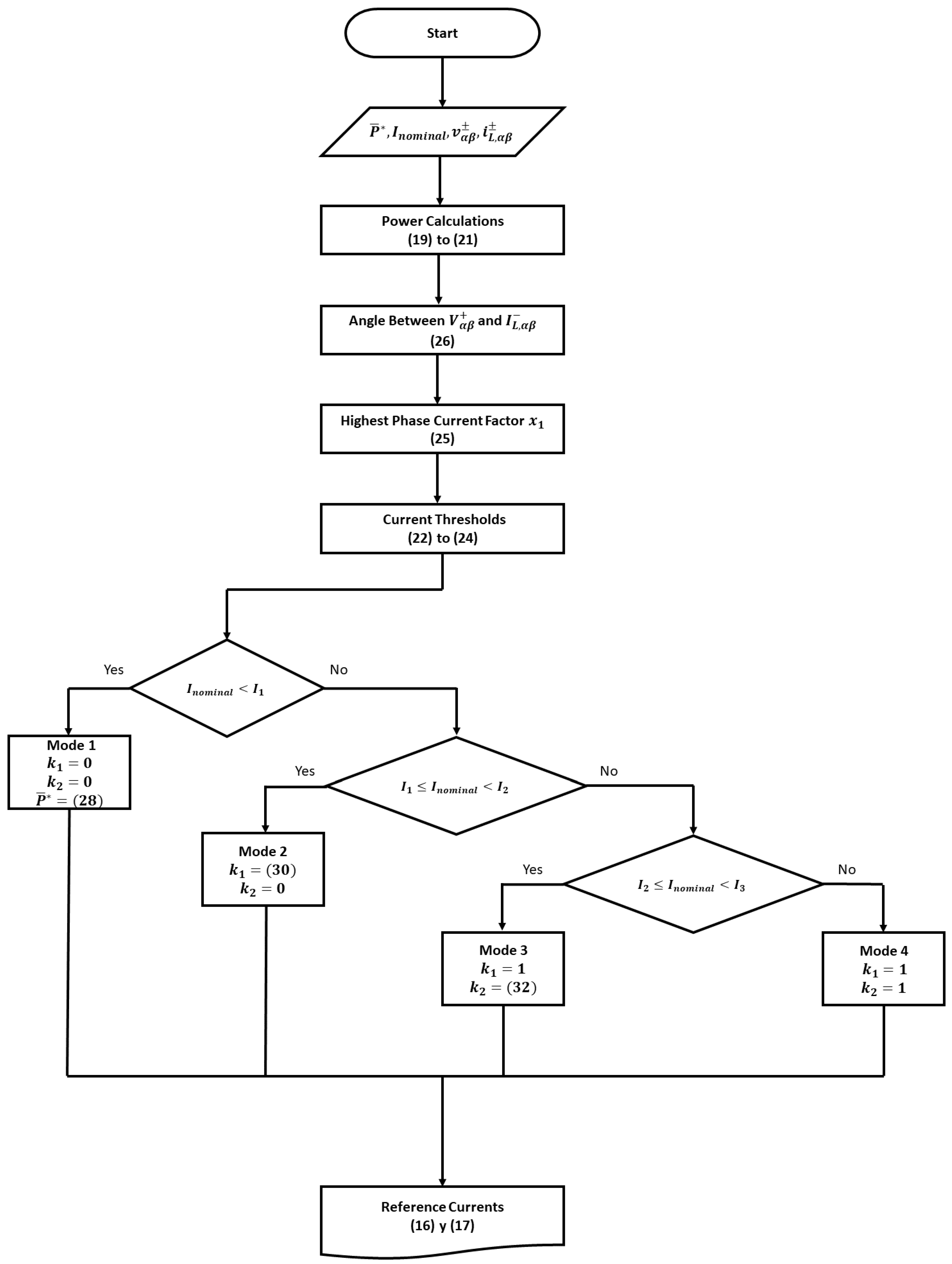
Four operating modes are defined for the multi-functional PV inverter, which are described below. The operating mode is determined by comparing the previously defined thresholds with the amplitude of the inverter’s nominal phase current (). For each mode, the values for the control parameters and are set, which allows limiting the inverter phase current according to the priority scheme.
In this operating mode, only average active power is injected into the grid; therefore, the two control parameters are set to zero, as shown in Equation (
27). Additionally, the reference value for the average active power (
) must be reduced according to the inverter’s nominal current, as specified in Equation (
28).
To achieve the reduction in the generated active power, it is necessary to operate the PV units at a non-MPPT mode using the active power curtailment (APC) control.
In this case, the total average active power (
) is injected into the grid, so the PV units work at the maximum power point. Furthermore, partial delivery of
is also possible. However, load unbalance compensation is not performed, so the control parameter
is set to zero, as seen in Equation (
29).
To limit the average component of the instantaneous reactive power delivered, based on the inverter’s nominal current, the control parameter
is defined as shown in Equation (
30). This definition ensures partial delivery of the reactive power demanded by the load while keeping the inverter current at its nominal value.
In this operating mode, both the total average active power (
) and the total average component of the instantaneous reactive power demanded by the load (
) are delivered by the PV inverter. So, the PV units work at the maximum power point and the control parameter
is set to the unit, as seen in Equation (
31).
Additionally, a partial delivery of the oscillating terms
and
is possible. To limit the load unbalance compensation capacity according to the inverter’s nominal current, the control parameter
is set as:
where
In this last operating mode, the three functionalities are fully achieved. So, the multi-functional PV inverter delivers the total average active power (
), the total average component of the instantaneous reactive power demanded by the load (
), and the total oscillating components of the instantaneous active and reactive powers demanded by the load (
and
, respectively). For this, the control parameters are set to one, as seen in Equation (
33). Once again, the PV units operate at the maximum power point.
Finally,
Figure 2 presents the flowchart of the proposed algorithm to control the multi-functional PV inverter. The algorithm considers the four operating modes for the inverter and the calculation of the reference currents, according to the planned control objectives.
4. Experimental Setup and Results
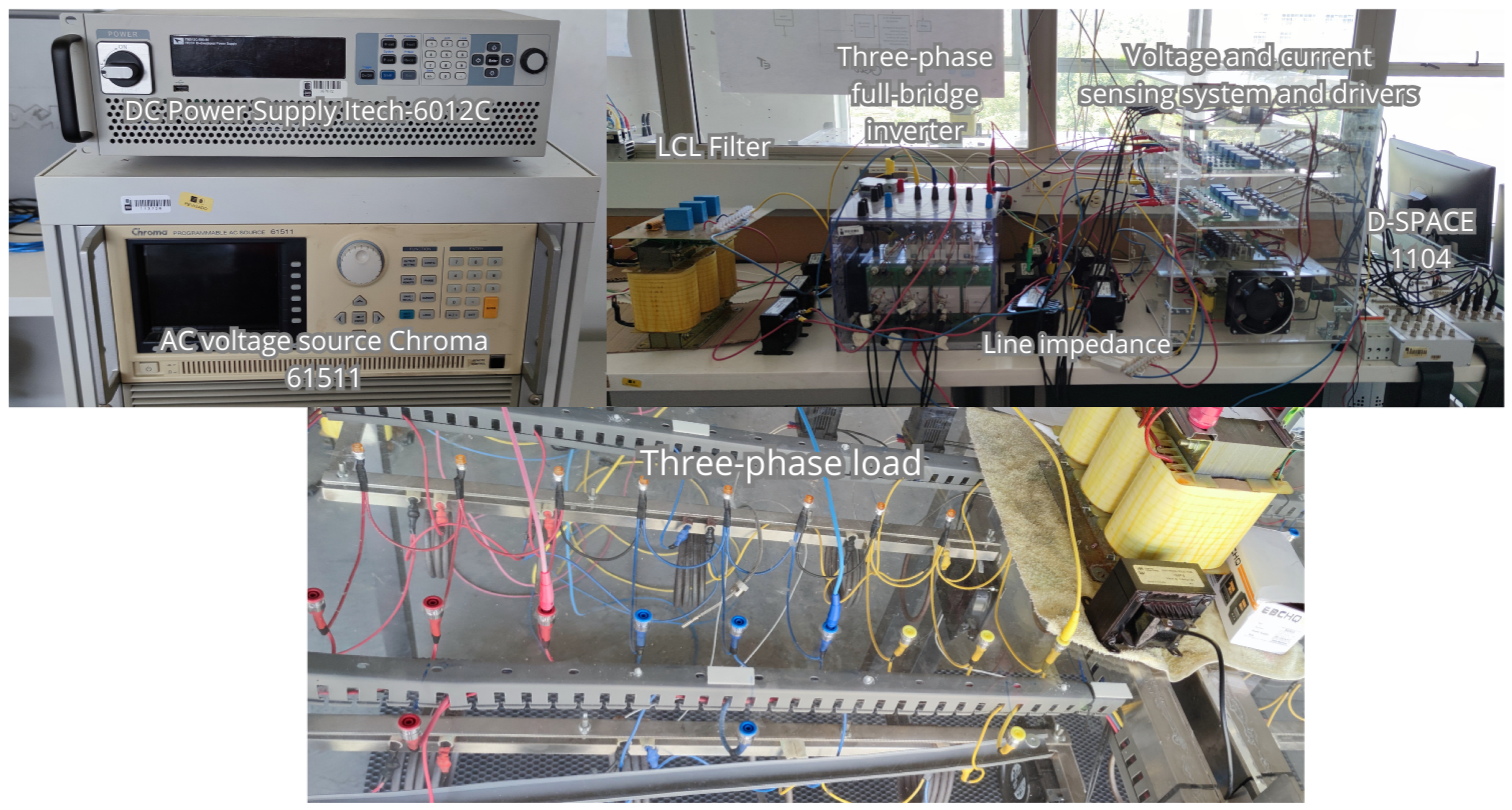
The performance of the proposed control strategy was evaluated through experimental testing on a multi-functional PV inverter prototype, following the configuration depicted in
Figure 1. In this setup, the PV generator, along with the DC/DC boost converter, was substituted by the programmable DC power supply Itech-6012C (ITECH Electronics Co., Ltd., Nanjing, China). This power supply was configured to maintain a constant voltage on the DC bus. Additionally, an AC programmable source Chroma 61511 (Chroma ATE Inc., Taoyuan City, Taiwan) and an RL line impedance were utilized to emulate the distribution network at the PCC. Moreover, an unbalanced three-phase load was connected to the PCC. The physical setup of the experimental prototype is shown in
Figure 3. For voltage sensing, LV 25-P transducers from LEM, along with OP470 operational amplifiers (Analog Devices, Inc., Norwood, MA, USA), were used. Similarly, for current sensing, LA 25-NP transducers from LEM, also with OP470 amplifiers, were utilized. The control algorithms were implemented on the d-SPACE 1104 controller board (dSPACE GmbH, Paderborn, Germany). The sensed signals were adapted for acquisition by the dSPACE card. These signals were visualized in the ControlDesk 5.3 environment and subsequently sent to MATLAB R2018b (MathWorks, Inc., Natick, MA, USA) to be plotted. The control algorithms implemented in the d-SPACE controller board include the sequence extractor, the current controller, the PWM technique, and the proposed strategy for generating the reference currents. The parameters of the system are detailed in
Table 1.
The experimental tests focus on evaluating the behavior of the system across the four operating modes defined in the proposed control algorithm. For this, four case studies are analyzed considering the amplitudes of the inverter’s nominal phase currents defined in
Table 2. All cases consider a generated active power (
) of 600 W. Likewise, ideal sinusoidal grid voltages are considered, i.e., sinusoidal positive sequence voltages at 60 Hz. During the tests, the system’s behavior was analyzed over a 0.5 s interval, with the inverter being activated at 0.1 s. In each case study, the dynamic adjustment of the two control parameters
and
is analyzed according to the operating mode and the established priority scheme.
Results for the four case studies are presented below.
4.1. Case 1
Figure 4,
Figure 5 and
Figure 6 illustrate the results of this first case study.
Figure 4 presents the grid currents (
,
, and
) and the currents injected into the grid by the PV system (
,
, and
).
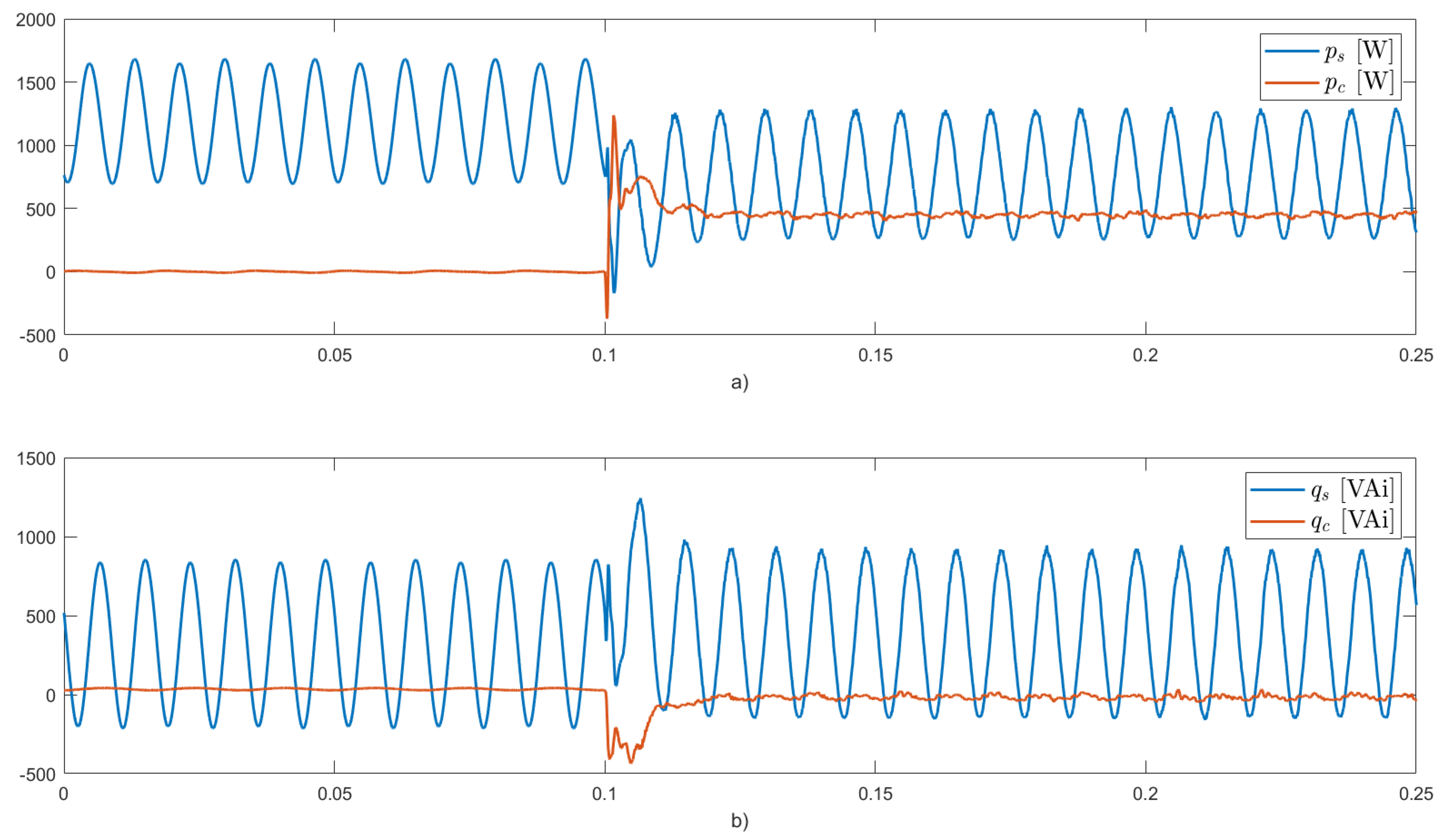
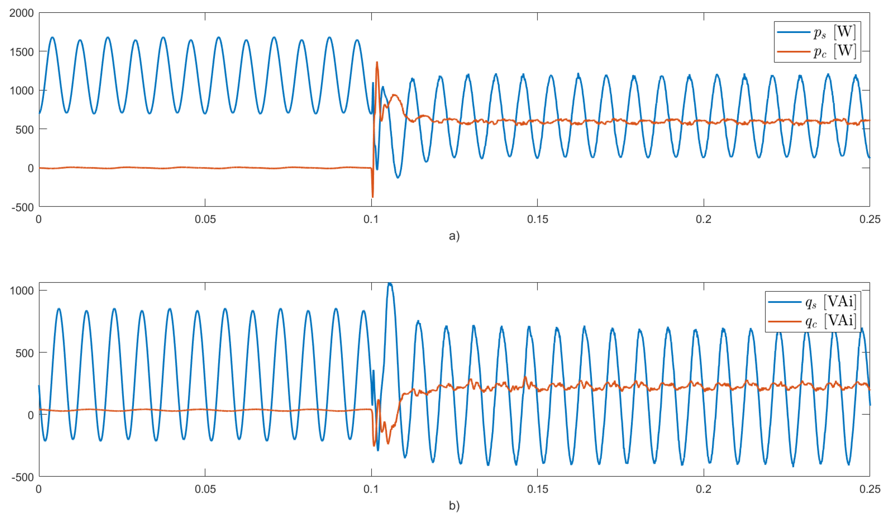
Figure 5 displays the instantaneous active and reactive powers in the grid (
and
), as well as those delivered by the PV system (
and
).
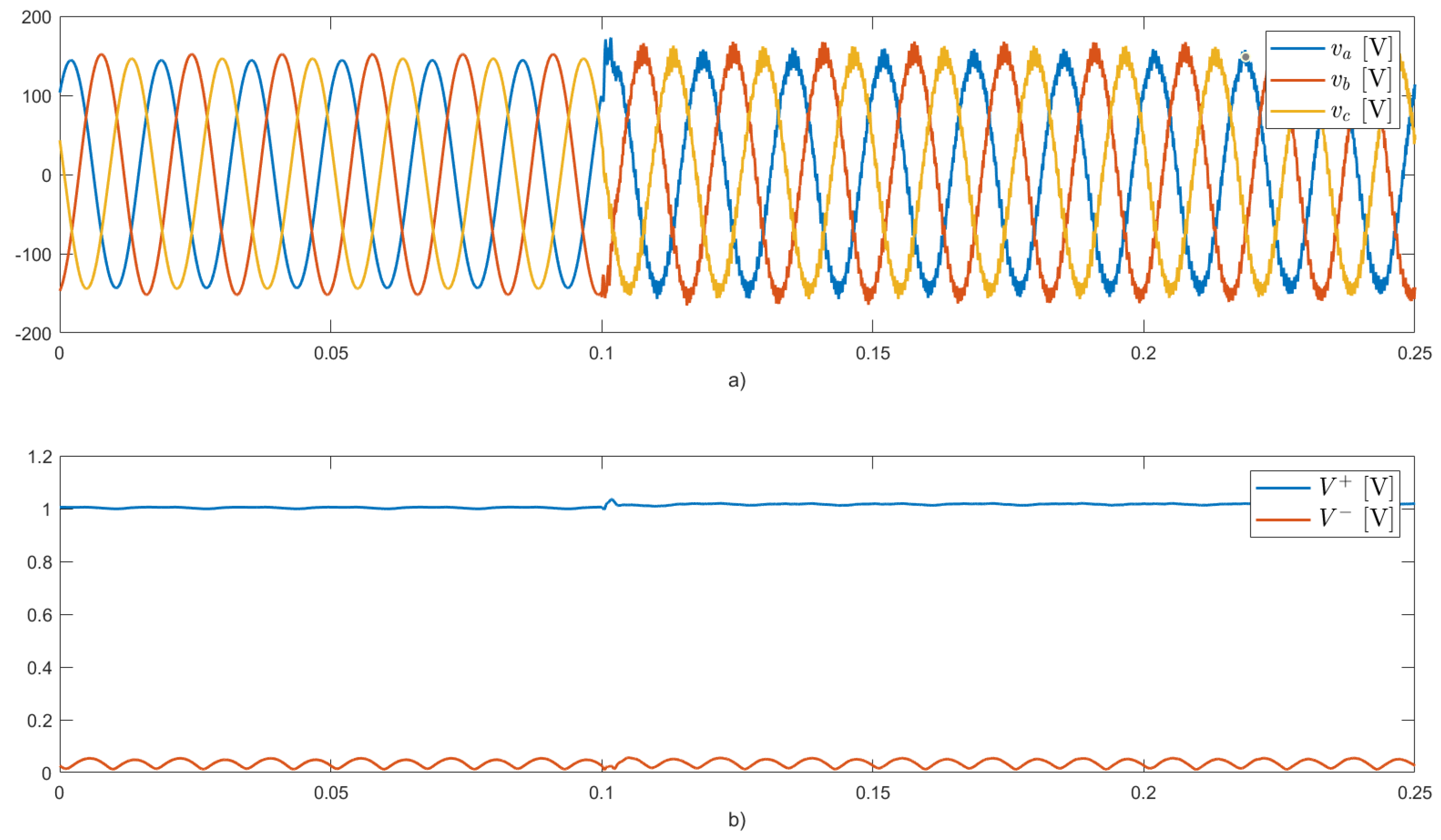
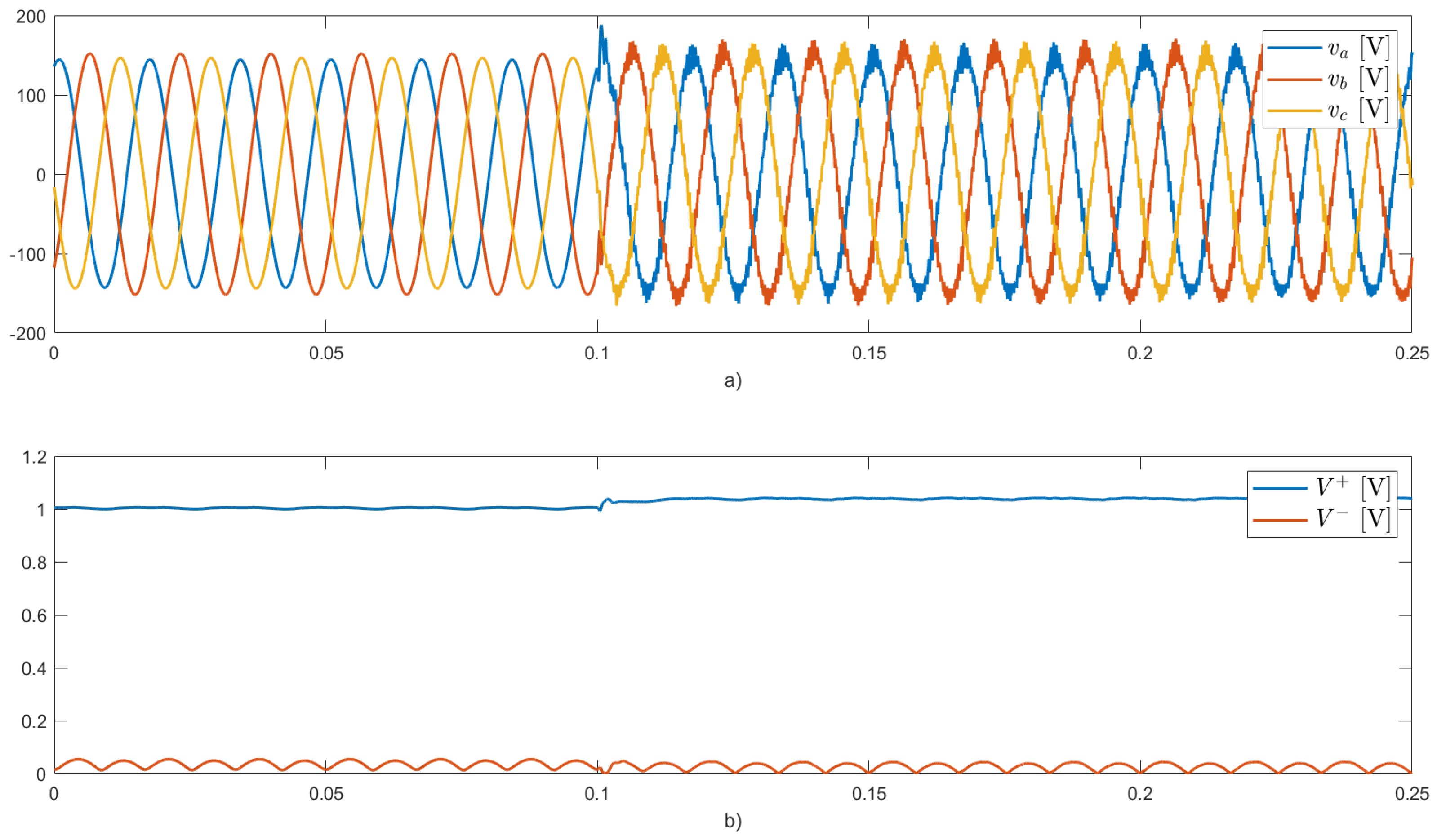
Figure 6 depicts the voltages at the PCC and the amplitudes per unit (p.u.) of its positive- and negative-sequence components.
Before activating the inverter (
[s]), the load currents are unbalanced and flow entirely through the grid, as seen in
Figure 4. The unbalanced load produces oscillating components in the instantaneous active and reactive powers demanded from the grid, as shown in
Figure 5. These components oscillate at twice the fundamental frequency due to the interaction between the negative sequence component of the load current and the positive sequence component of the PCC voltages. Additionally, the instantaneous reactive power demanded by the load contains an average component due to the inductive element connected in phase
a. This behavior before activating the inverter (
[s]) is the same for the four case studies.
After activating the inverter (
[s]), the multi-functional PV inverter works in operating
mode 1. The control parameters
and
are set to zero, so only average active power is injected into the grid. However, the inverter’s capacity cannot handle the total generated active power (600 W), because the injected currents would exceed the inverter’s nominal phase current (2 [A]). To address this issue, the control algorithm reduces the reference average active power (
), ensuring the injected currents remain within the maximum limit the inverter can support, as seen in
Figure 4. This reduction in active power requires PV units to be operated in a non-MPPT mode using the APC control.
The grid currents decrease in amplitude as a portion of the average active power consumed by the load is supplied by the PV system. However, no compensation functionalities are performed in this mode, so the grid currents remain unbalanced. The grid continues to supply the average part of
, as well as the oscillating components of the instantaneous active and reactive powers demanded by the load (
and
), as seen in
Figure 5. In this case, the multi-functional PV inverter does not improve the power quality in the grid.
The PV system injects balanced positive sequence currents, with a maximum amplitude limited by the inverter’s capacity (see
Figure 4). Moreover, the voltages at the PCC show a slight increase due to the injection of active power, as shown in
Figure 6.
4.2. Case 2
Figure 7,
Figure 8,
Figure 9 and
Figure 10 illustrate the results for the second case. After
[s], the multi-functional PV inverter operates in
mode 2. The control parameter
is set to zero, as shown in
Figure 9, so unbalanced load compensation is not performed. In this case, the inverter delivers the total average active power (600 W), as well as a portion of the average part of the instantaneous reactive power demanded by the load, as seen in
Figure 8. The control parameter
dynamically adapted to ensure the injected currents (see
Figure 7) remain within the inverter’s nominal current (
[A]), as seen in
Figure 9.
The PV system injects balanced positive sequence currents, as shown in
Figure 7. The grid currents remain unbalanced as the inverter does not perform load balancing functions. It is observed that the grid currents decrease in amplitude compared to case 1 since the inverter compensates for a portion of the reactive power consumed by the load. The grid continues to supply a partial part of
, as well as the total oscillating components of the instantaneous active and reactive powers demanded by the load (
and
), as seen in
Figure 8. In this case, the multi-functional PV inverter does not improve the current unbalances in the grid.
As shown in
Figure 10, the voltages at the PCC increase in amplitude due to the injection of both active and reactive power.
4.3. Case 3
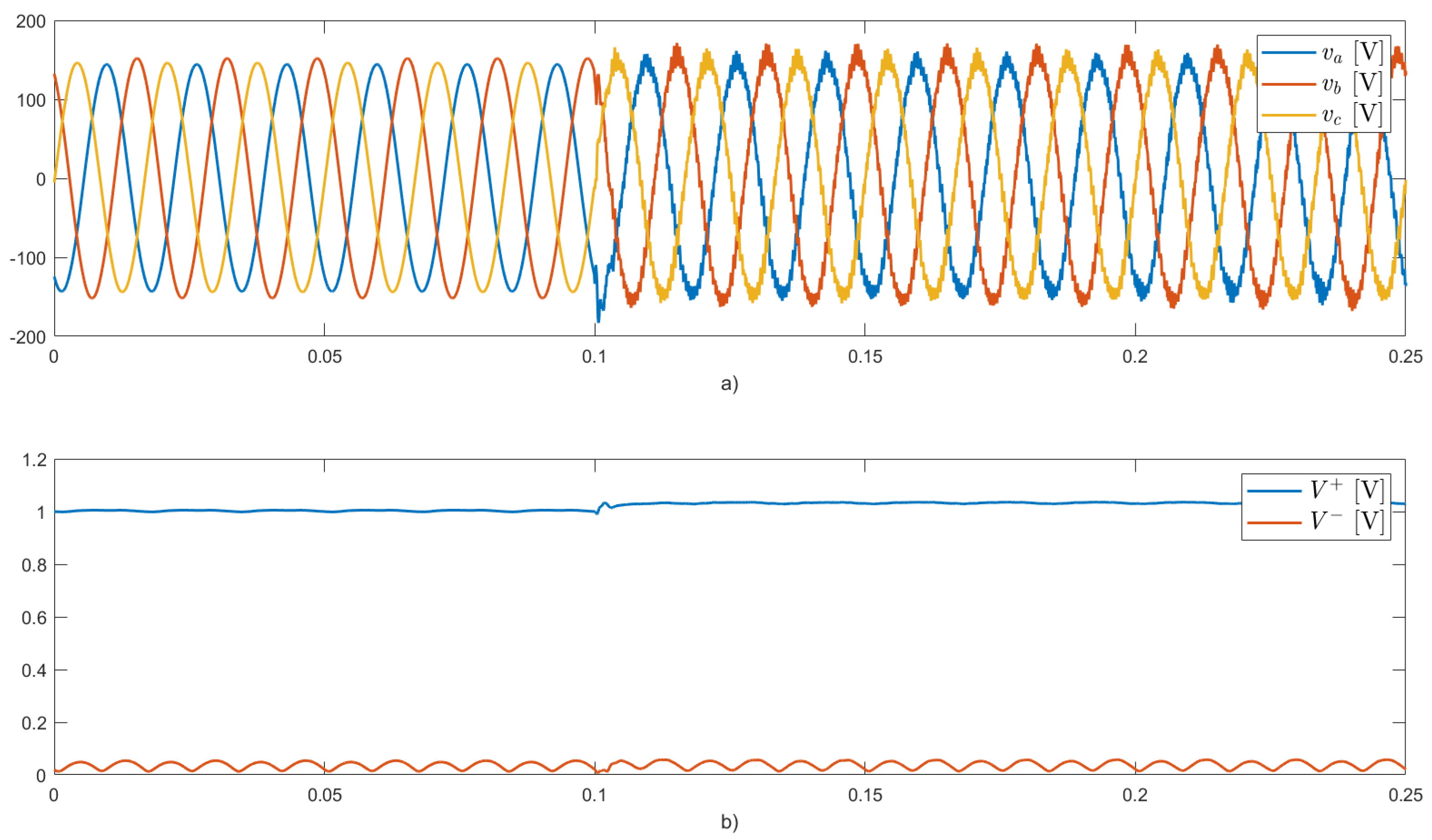
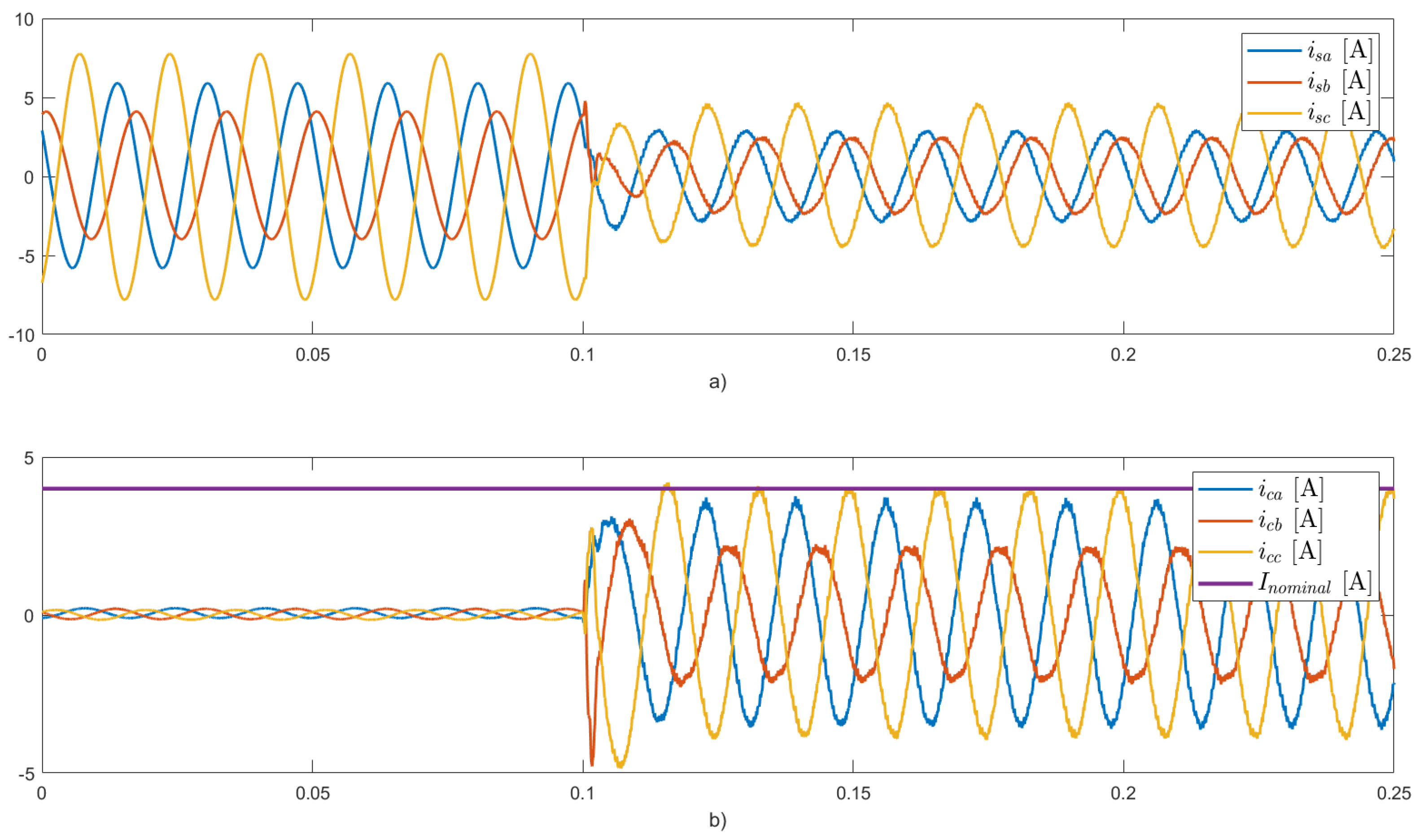
The results for this case are presented in
Figure 11,
Figure 12,
Figure 13 and
Figure 14. After activating the inverter (
[s]), the multi-functional PV system works in operating
mode 3. In this case, the inverter delivers the total average active power (600 W), the total average component of the instantaneous reactive power demanded by the load, and a partial component of the oscillating parts of the instantaneous active and reactive powers demanded by the load (
and
), as seen in
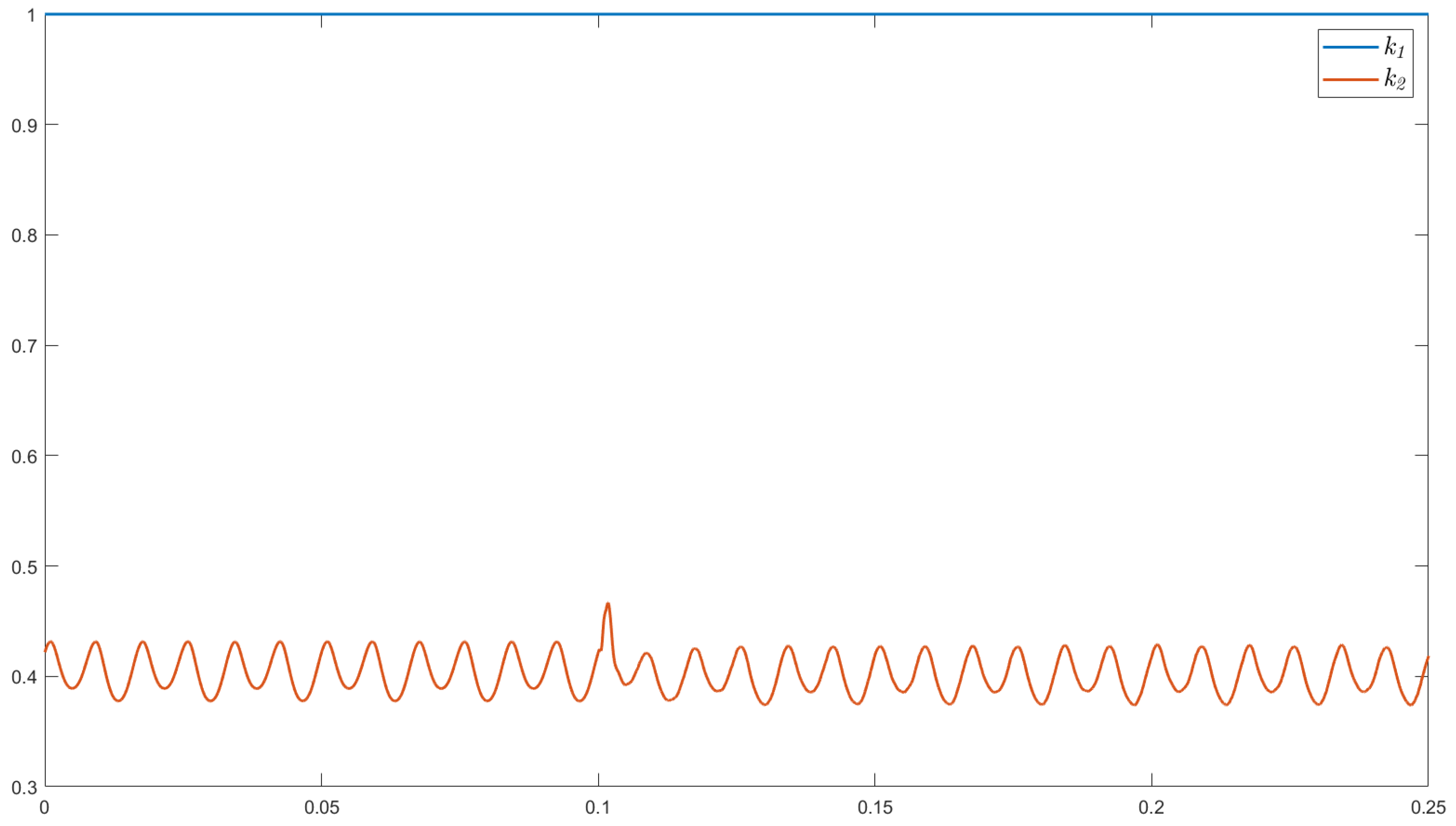
Figure 12.
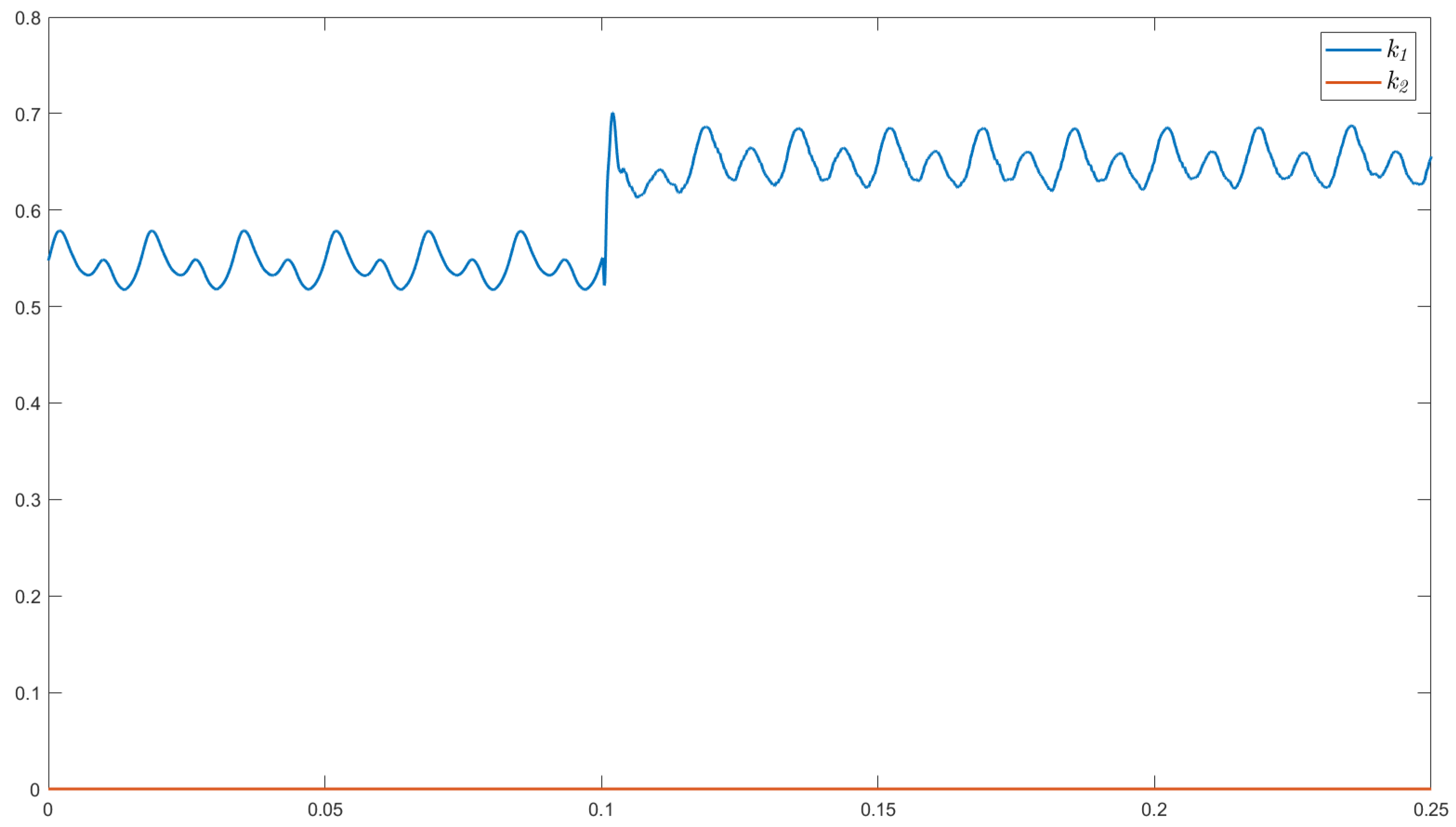
Figure 13 shows that the control parameter
is set to unity, while
dynamically adapted to limit the load balancing functionality, ensuring the injected currents (see
Figure 11) remain within the inverter’s nominal current (4 [A]).
The grid currents decrease in amplitude compared to cases 1 and 2, as seen in
Figure 11. The PV system no longer injects only balanced positive sequence currents since load balancing functionalities are incorporated. Instead, the PV system also injects part of the negative sequence component of the load current, so the resulting injected currents are unbalanced. This results in an improvement in grid power quality due to the compensation capabilities included in the PV inverter. As depicted in
Figure 14, the voltages at the PCC exhibit behavior similar to that of the previous cases.
4.4. Case 4
Figure 15,
Figure 16 and
Figure 17 present the resulting signals for case 4. After
[s], the multi-functional PV inverter operates in
mode 4, in which the two control parameters are set to 1. In this operating mode, the inverter delivers the total average active power (600 W) and compensates for both the total average component of the instantaneous reactive power demanded by the load (
) and the total oscillating parts of the instantaneous active and reactive powers demanded by the load (
and
), as seen in
Figure 16. The PV inverter performs all the functionalities according to the proposed objectives.
As shown in
Figure 15, the resulting grid currents are balanced positive sequence signals with the minimum RMS value required to satisfy the active power demanded by the load. The multi-functional PV inverter compensates for the power factor and the unbalanced load, resulting in improved grid power quality. On the other hand, the inverter injects unbalanced currents (see
Figure 15), which are necessary to perform the compensation functions. The amplitudes of the injected currents are below the inverter’s nominal current (6 [A]) for the three phases, thus meeting the current limitation objective.
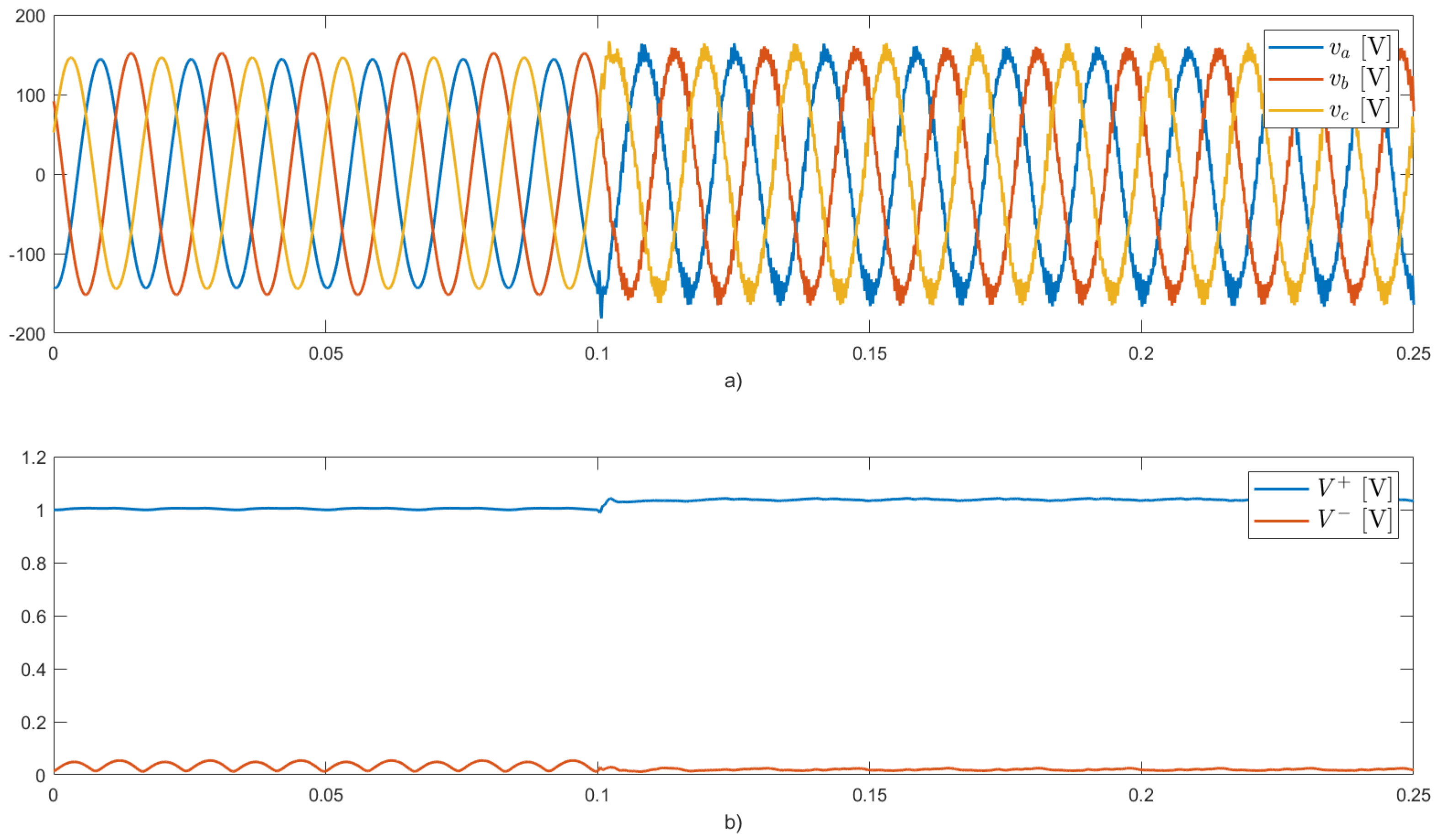
The voltages at the PCC show improvement, as illustrated in
Figure 17. Once the inverter is activated, the amplitude of the negative sequence component of the PCC voltage (
) decreases almost to zero, as the negative sequence component of the load current is mitigated in the grid. Likewise, there is an increase in the positive sequence component of the PCC voltage.
4.5. Discussion
The results demonstrate significant improvements in grid power quality achievable through the implementation of the proposed flexible control strategy in PV inverters. Specifically, the strategy leverages real-time adjustment of control parameters and the integration of power factor correction and load balancing functionalities, enhancing the inverter’s performance. Unlike conventional methods, this approach allows for adaptive operation based on load and power generation conditions, providing a robust solution for modern power systems.
A comparison with relevant published studies highlights the novelty of the proposed approach. Previous research, such as [
18,
19], primarily focused on conventional and dynamic saturation techniques to limit the peak current injected by the multi-functional PV inverter. Although these techniques limit the injected current according to the inverter’s rated capacity, they lack flexibility. Consequently, the compensation functionalities cannot be prioritized according to defined objectives. In [
20,
21], two approaches are proposed to control multi-functional PV inverters. These works propose power management strategies that give priority to the inverter functionalities. Although these strategies prioritize specific compensation objectives, their performance under unbalanced load conditions is not analyzed or considered. Compared to previously mentioned works, the proposed flexible control strategy integrates load balancing functionalities and peak current limitation by dynamically adjusting control parameters, a significant advancement over existing methods. This comparison underscores the innovative aspects of the approach and its potential impact on enhancing grid power quality.
While the proposed strategy shows promising results, addressing common operational aspects of PV systems, such as rapidly changing load conditions and highly dynamic environments, is essential. Future research should prioritize testing the control strategy under these conditions to ensure its robustness and effectiveness. Expanding case studies to include scenarios with high load variability and dynamic changes will offer a more comprehensive understanding of the system’s performance.
The experimental validation in this study was performed on a prototype system. Future work should include scaling the experimental setup and testing in larger installations to evaluate the applicability of the proposed control strategy for larger PV systems. This will help determine the feasibility and effectiveness of the control strategy in real-world large-scale PV systems, where the complexity and dynamics of the environment can be relevant to the system’s operational performance.
Further investigation is required to assess the applicability of the proposed method for integrating low voltage ride through (LVRT) capabilities and compensating for harmonic currents caused by non-linear loads. Ongoing efforts are directed toward limiting the injected peak current, considering that with the integration of harmonic mitigation capabilities, the injected current deviates from a pure sinusoidal waveform. These investigations will provide a comprehensive understanding of the method’s capabilities and limitations, ensuring its applicability in a broader range of operational conditions.


