Article

Investigation on Melting Process of Finned Thermal Energy Storage with Rotational Actuation

1
Xi’an Aeronautics Computing Technique Research Institute, AVIC, Xi’an 710068, China
2
Institute of the Building Environment & Sustainability Technology, School of Human Settlements and Civil Engineering, Xi’an Jiaotong University, Xi’an 710049, China
*
Author to whom correspondence should be addressed.
Energies 2024, 17(17), 4209; https://doi.org/10.3390/en17174209
Submission received: 18 July 2024 / Revised: 7 August 2024 / Accepted: 21 August 2024 / Published: 23 August 2024
(This article belongs to the Topic Thermal Energy Transfer and Storage)

Abstract

Phase-change thermal storage is essential for renewable energy utilization, addressing spatiotemporal energy transfer imbalances. However, enhancing heat transfer in pure phase-change materials (PCMs) has been challenging due to their low thermal conductivity. Rotational actuation, as an active method, improves heat transfer and storage efficiency. This study numerically examined the melting behavior of finned thermal storage units at various rotational speeds. The influence of speed was analyzed via melting time, rate, phase interface, temperature, and flow distribution. Results showed that rotational speed effects were non-monotonic: excessive speeds may hinder complete melting or reduce efficiency. There existed an optimal speed for the fastest melting rate and a limited speed range for complete melting. At the preferred rotation speed of 2.296 rad·s−1, the utilization of PCMs in a finned tube could mitigate the risk of local overheating by 97.2% compared to a static tube, while improving heat storage efficiency by 204.9%.

1. Introduction

The functioning of human society depends heavily on energy consumption [1,2], and the reliance on fossil fuels had resulted in significant detrimental environmental impacts, particularly with regard to the greenhouse effect. Approximately one-third of global energy consumption in buildings is used in heating, cooling, and equipment. An ongoing challenge in building energy conservation was the reduction of carbon emissions stemming from energy consumption, making the utilization of renewable energy a focal concern. While renewable energy held considerable promise, it also presented persistent issues. For instance, the utilization efficiency of solar energy was hindered by its temporal and spatial discontinuity [3]. Thermal energy storage (TES) then emerged as an effective and cost-efficient technology [4,5], capable of storing solar heat during periods of low-demand and providing it when the heating requirement was higher [6,7].
Heat storage methods, including sensible heat storage [8], latent heat storage [9], and thermochemical storage [10] as the main heat storage technologies [11], have been favored in recent years. In particular, the utilization of PCMs [12], capitalizing on its high heat storage density and wide operating temperature range, could potentially reduce the quantity and dimensions of storage tank units in the heat storage system, thereby enhancing its economic viability and reliability [13,14,15]. Consequently, research on and utilization of PCMs could effectively drive the advancement of LHTES (latent heat thermal energy storage) [16]. The small thermal conductivity of PCMs causes a direct impact on its thermal storage efficiency [17], presenting a significant challenge that has hindered its broad-scale application [18]. Thus, implementing effective measures to promote the heat transfer performance of PCMs in LHTES will unquestionably expand its application prospects [19,20].
The methods of heat transfer enhancement for PCMs could generally be categorized as passive enhancement [21,22] and active enhancement [23]. Passive strengthening techniques such as the addition of foam [24], nanoparticles [25], fins [26], and encapsulated PCMs [27] were proven to effectively strengthen the heat transfer of PCMs, leading to a notable increase in heat storage and heat release efficiency. Bian et al. [28] conducted research on the heat transfer behavior of porous metal foam with paraffin as PCMs in various shapes and porosity gradients, which indicated that the gradient model and foam with a moderate porosity gradient difference could effectively reduce the complete melting time. Poyyamozhi et al. [29] optimized the energy storage capacity of PCMs and nanoparticle composite phase-change materials by the response surface method. The result showed that AgTiO2 and CNT nanoparticles increased the heat storage capacity of PCMs by 7.48% and 3.82%, respectively. Boujelbene et al. [30] explored the difference between twisted fins and straight fins on the heat charging and release behavior of PCMs. The heat charging and release rate of twisted fins were able to be increased by 10% and 14% respectively compared to that of straight fins.
In comparison to passive enhancement, the incorporation of active measures such as electric field [31], magnetic field [32], ultrasound [33], and rotation [34,35] were more significant. At the initial stage of the solid–liquid phase-change process, heat transfer was primarily conducted through thermal conduction. However, once the liquid phase material began to appear, convective heat transfer became the dominant mechanism. Passive enhancement techniques typically improve thermal conduction, while active enhancement measures significantly enhance convective heat transfer during the solid–liquid phase-change process, which greatly accelerates the melting process within the thermal energy storage tube. Anggraini et al. [36] introduced dopants like Fe3O4 and CoFe2O4 to PCMs to analyze the coagulation rate of PCMs under the magnetic field. These findings revealed that Fe3O4 and CoFe2O4 increase the solidification rate by 42% and 33%, respectively, leading to a considerable reduction in solidification time. Khanmohammadi et al. [37] employed ultrasonic-assisted PCMs to cool a hot plate, achieving superior cooling effectiveness compared to pure PCMs.
Nevertheless, the incorporation of electric, magnetic, or ultrasonic fields in PCMs presented significant additional power consumption. Conversely, the rotation strategy, characterized by its simple technology and relatively low power consumption, demonstrated relatively high cost-efficiency in the PCM heat transfer process. Kumar et al. [38] implemented a rotation strategy in a novel rotating three-tube sinusoidal finned heat storage tube, with results indicating the heat release rate of PCMs increased with the rotational speed. Fathi et al. [39] utilized an active rotation strategy in the latent heat storage device through experiments, showing that the melting time of PCMs could be significantly shortened at higher rotational speeds, with a reduction of about 50% compared to a static tube. Guo et al. [40] investigated the rotation of the widely used finned latent heat tube, with numerous numerical simulations demonstrating that a specific rotational speed effectively shortened the fully melting time of paraffin, and approximately determining the better rotation speed.
The literature review above illustrated that utilizing a rotation strategy could effectively aid in making faster heat storage and addressing the issue of poor thermal conductivity of PCMs. Nonetheless, for widely used finned tubes, the behavior characteristics of different rotation speeds of PCM necessitated further investigation. In this study, a reliable numerical simulation model for finned solid–liquid phase-change thermal storage units under rotational drive was established and validated. Then, the influence of different rotation speeds (0~5 rad·s−1) on the melting behavior of PCMs was examined. The melting time, melting rate, phase interface morphology, temperature distribution, and velocity distribution were quantitatively and qualitatively presented. An in-depth discussion on how rotation strategy strengthens heat transfer of PCM in TES tubes followed.

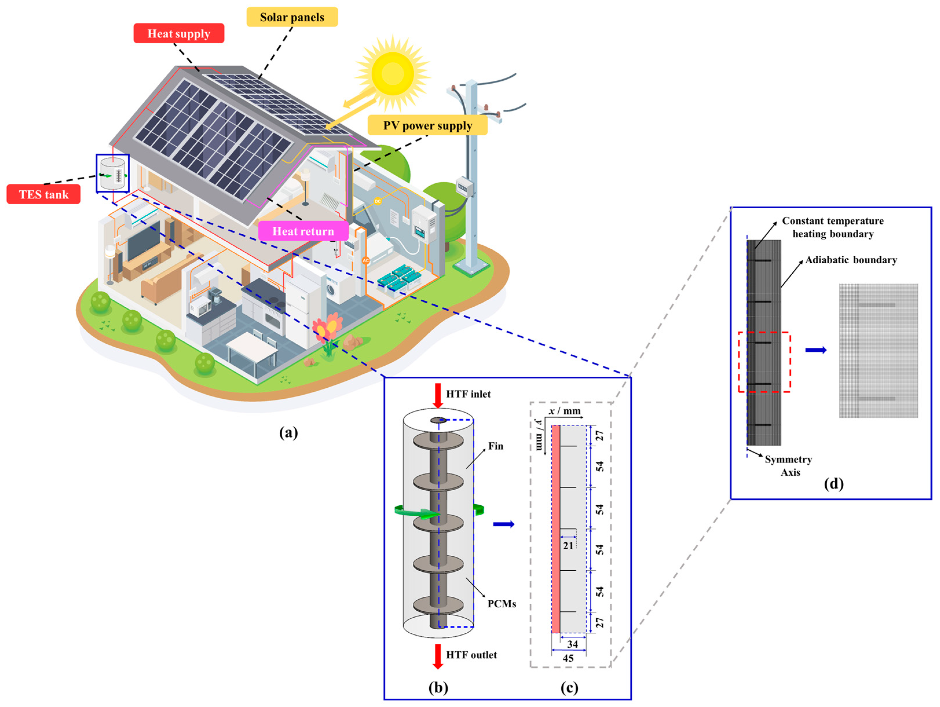
2. Description of Physical Model

Figure 1a depicted the solar thermal photovoltaic system within a low-carbon building. The direct current generated by the photovoltaic panels and the alternating current from the grid collectively fulfilled the building’s electricity requirements. Simultaneously, to address the reduced photoelectric conversion efficiency due to the heating of the photovoltaic panels, the waste heat generated by this process could be harnessed to supply free heat for building heating and domestic hot water. Currently, the utilization of metal-finned heat storage tanks has allowed multiple heat storage units to be arranged in parallel or in series, significantly enhancing heat storage efficiency. To conserve computational resources and improve the efficiency of numerical calculations during the simulation process, the 3D physical model of the finned tube was simplified in this study, as demonstrated in Figure 1b, resulting in the derivation of the 2D calculation domain, as presented in Figure 1c. Within this calculation domain, the outer tube had a radius of 45 mm, the inner tube had a radius of 11 mm (with a 1 mm wall thickness for the heat transfer copper tube), and five fins (21 mm in length and 2 mm in thickness) were equally spaced. All computing domains were divided into structured grids with a mesh mass of almost 1, as shown in Figure 1d. For this study, water flowed in the heat exchange copper tube, providing heat for the PCM. Detailed thermophysical properties of these materials were provided in Table 1. A rotational mechanism was installed to drive the entire heat storage tube as shown in Figure 1b, including the inner finned tube and the whole PCM tank.

3. Numerical Simulation Method

3.1. Governing Equations

The Enthalpy-Porosity model was utilized in this study to simulate the melting process of PCMs, and several necessary assumptions were made:
(1)
Paraffin is an incompressible Newtonian fluid.
(2)
Except for temperature and density during phase transition, the thermophysical properties of PCMs are constant, and the change of density follows the Boussinesq approximation [41].
(3)
Volume change of PCMs is ignored [42].
(4)
The thermal radiation between the solid liquid thermal energy storage unit and the surrounding environment was ignored.
Based on these assumptions, the following governing equations were utilized.
For HTF [41]:
u = 0
ρ HTF u t + ρ HTF ( u ) u = P + μ HTF 2 u
ρ HTF c p HTF T t + ρ HTF c p HTF u T = ( k HTF T )
In addition, for PCMs:
u = 0
ρ f u t + ρ f ( u ) u = P + μ f 2 u + ρ f g β ( T f T m ) + A u
ρ f c p f T f t + ρ f c p f u T f = ( k f T f ) ρ f L f l t
where A in Equation (5) represents the damping coefficient of the velocity in the PCM solid phase, and the details are given in Equation (7) [43]:
A = ( 1 f l ) A m u s h f l 3 + S
where Amush and S represent a larger constant and a smaller constant, which were set to 105 [44] and 10−3 [45], separately. Additionally, fl was the liquid fraction of the PCM, which is defined in Equation (8) [46]:
f l = 0 T < T s o l i d s o l i d T T s o l i d T l i q u i d T s o l i d T s o l i d < T < T l i q u i d m u s h y 1 T l i q u i d < T l i q u i d
where Tsolid and Tliquid represent the solid phase temperature and liquid phase temperature of the PCM, and the specific values were 50 °C and 55 °C, respectively.

3.2. Boundary and Initial Conditions

The 2D numerical model was able to be roughly divided into four regions: HTF, tube wall, fins, and PCM.
For HTF, the inlet boundary condition of HTF was selected as the velocity-inlet, while an outflow boundary condition was set at the HTF outlet. The flow rate and temperature are defined below:
V inlet = V outlet = 1.0   m s 1 ,   T inlet = T outlet = 70   ° C
assuming that there is no heat exchange between the outer wall of tube and the environment air. Except for inlet and outlet walls, the boundaries of other walls are set as insulated. The initial temperature of all regions is defined in Equation (10):
t = 0 ,   T = 25   ° C
where t denotes the current melting time.
In addition, this is assuming no slip between the PCM and fins, which are represented in Equations (11) and (12):
T fins | Ω = T PCMs | Ω
λ PCMs T fins n Ω = λ fins T PCMs n Ω

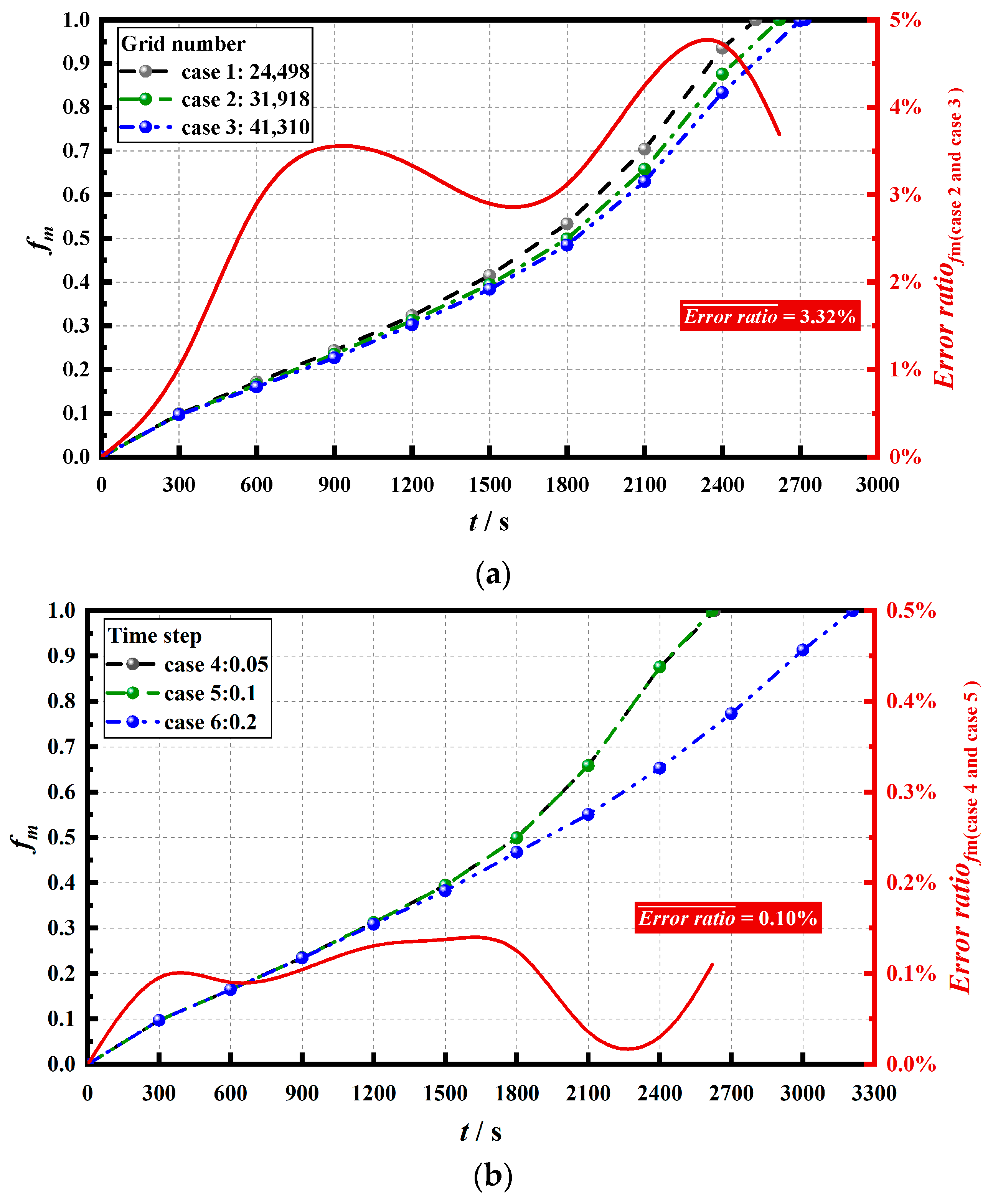
3.3. Numerical Method and Feasibility Analysis

Utilizing the CFD solver of ANSYS-Fluent 2019 R3, the finite volume method (FVM) was applied to compute and analyze the established numerical model. The spatial discretization of pressure utilized the PRESTO! algorithm, while the energy and momentum equations were discretized utilizing the second order upwind method. Additionally, underrelaxation factors of 0.9, 0.3, 0.7, and 1.0 were applied to the liquid fraction, pressure, momentum, and energy, separately, to ensure the convergence, while maintaining a threshold of 10−6.
Prior to numerical computation, the mesh number and time step were independently tested to establish a computationally efficient numerical model with acceptable accuracy. For example, at a rotation speed of 2 rad·s−1, models with mesh numbers of 24,498, 31,918, and 41,310, and time steps of 0.05, 0.1, and 0.2 were tested, with results presented in Figure 2. Figure 2a demonstrated that, unlike in case 3, case 2 exhibited a maximum error of less than 5% and an average error of 3.32%. Additionally, setting the time step to 0.05 yielded results consistent with those at 0.1, with a maximum error of less than 0.15% and an average error of 0.10%, as shown in Figure 2b. Consequently, under comprehensive consideration of computational efficiency and accuracy, the grid system number and time step of the model in this study were set at 31,918 and 0.1 s.

3.4. Numerical Model Validation

Soltani et al. [47] investigated the melting characteristics of PCMs in finned tubes under an active rotation strategy. This study’s simulation results were compared with those of Soltani et al. utilizing the same physical model and boundary conditions. The liquid phase fraction and average temperature results are demonstrated in Figure 3a and Figure 3b, separately. These findings indicated a basic consistency in the trends of liquid fraction and mean temperature, with mean errors of less than 5.9% and 1.5%, respectively, implying the relatively reliable nature of the numerical model established in our research.

4. Research Results and Analysis

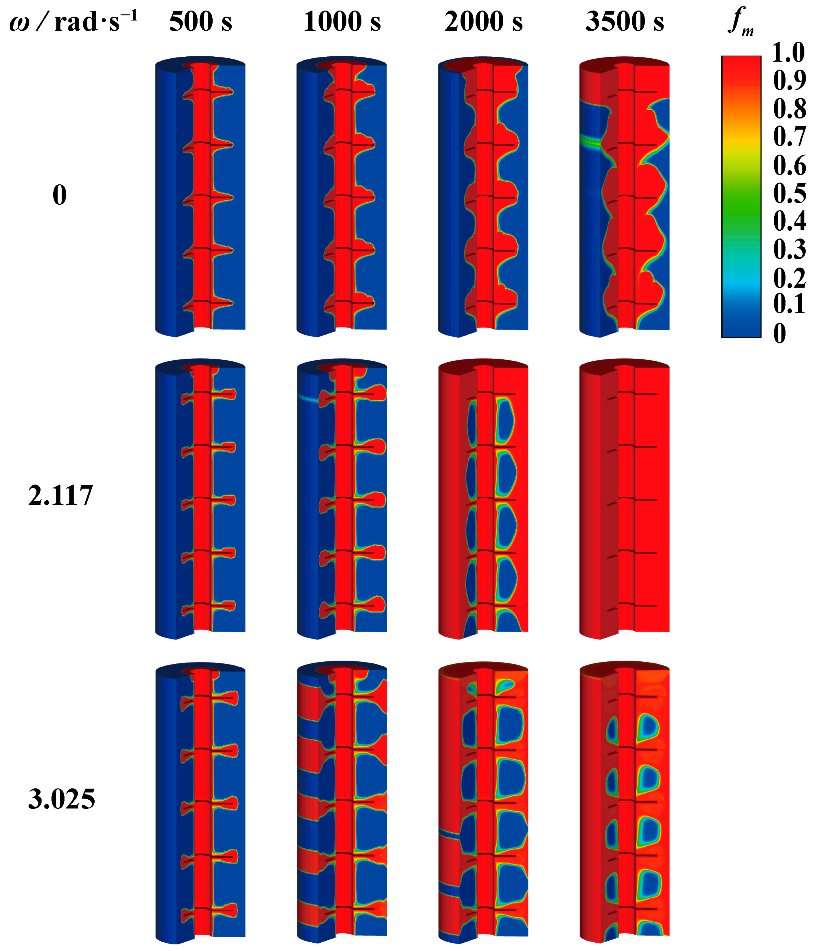
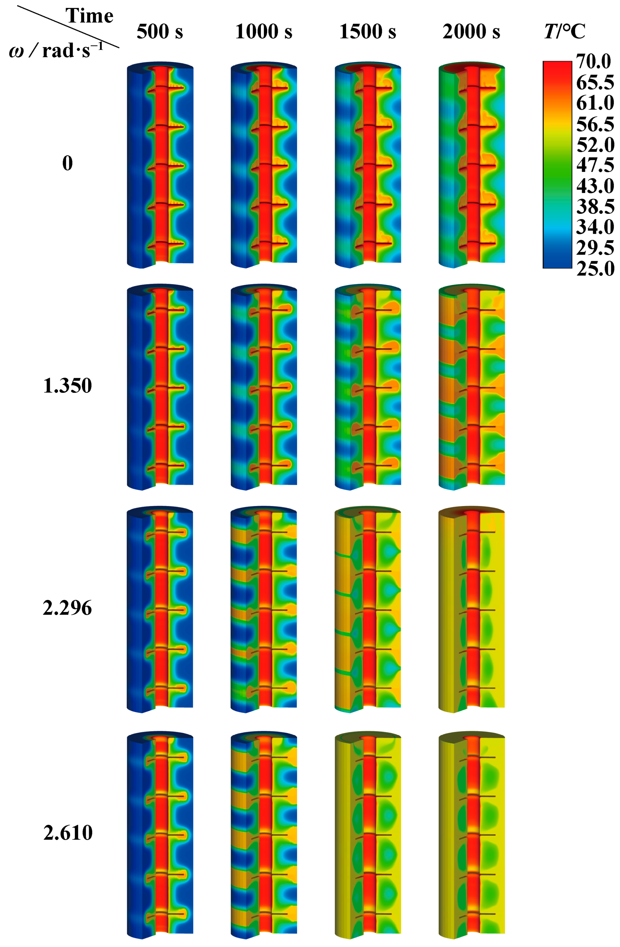
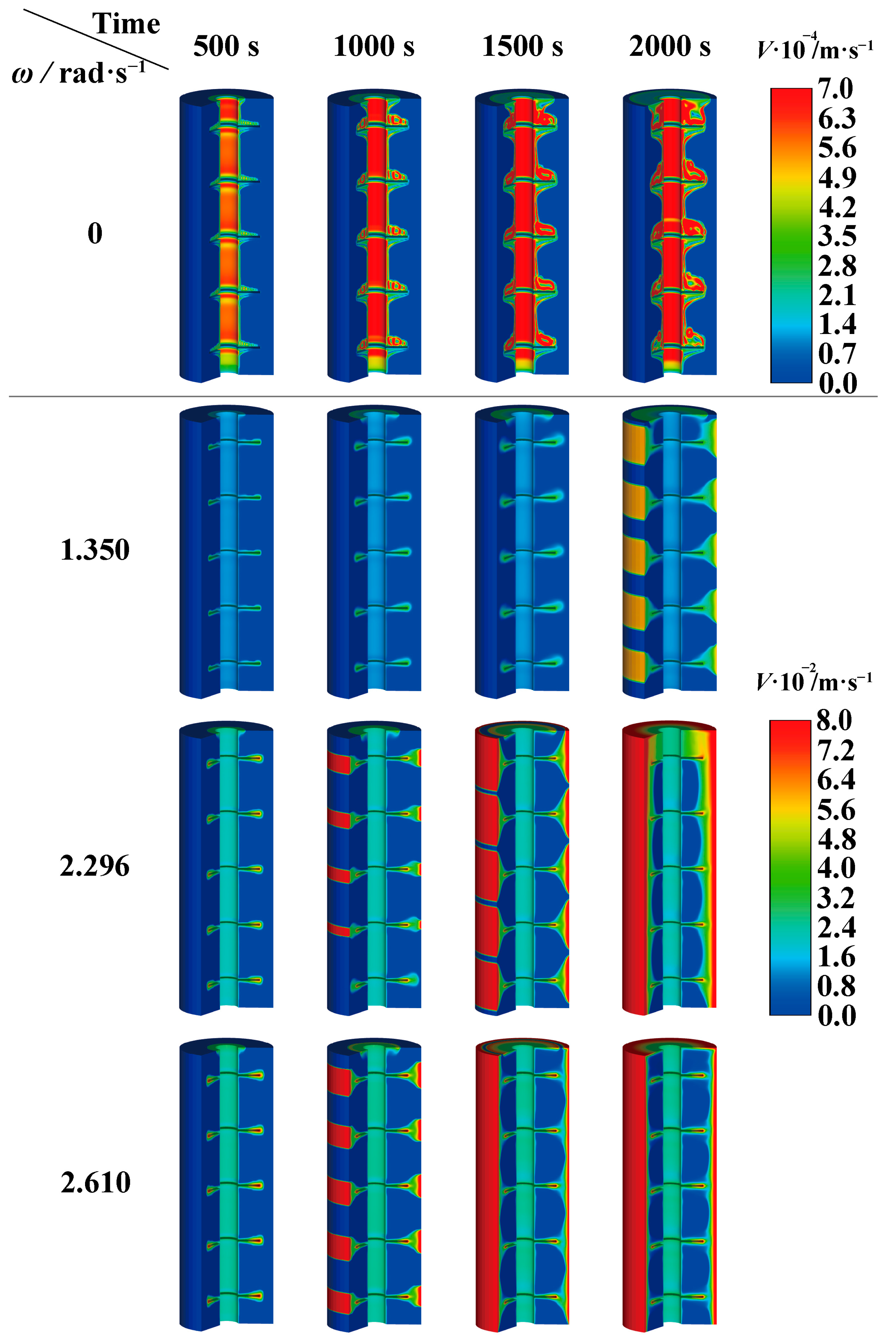
4.1. Influence of Rotation Strategy on Melting of PCM

To explore how rotation strategy affected the melting of PCMs in TES tubes, 12 cases were designed with rotation speeds ranging from 0 rad·s−1 to 5 rad·s−1 using Design-Expert 13.0, and the details are shown in Table 2.
Figure 4 illustrates the PCM melting details at different rotational speeds. It was noteworthy that for cases 8 to 12, their maximum liquid phase fraction was less than one, indicating that excessively high rotation speeds prevented complete PCM melting. Moreover, for cases 2 to 7, when the rotational speed was less than 2.500 rad·s−1, their maximum liquid phase fraction reached one, signifying complete PCM melting, with their complete melting time being shorter than that of non-rotating case 1. Furthermore, an intriguing finding was noted: for cases 2 to 7, higher rotational speeds did not necessarily translate to improved melting efficiency. In comparison to case 1, the decrease in their complete melting time initially decreased but then increased. Notably, case 6 achieved the shortest complete melting time, 70.59% shorter than that of case 1, indicating considerable acceleration of the PCM melting process when the rotational speed was 2.117 rad·s−1.
Figure 5 depicts the change in the transient liquid fraction in TES tubes at different rotational speeds over time. For cases 2 to 6, which achieved complete melting, a larger rotational speed corresponds to a steeper slope of the liquid phase fraction curve, indicating greater PCM melting enhancement. However, when the rotational speed was 2.117 rad·s−1, case 7 demonstrated a faster melting efficiency than at 2.500 rad·s−1 after approximately 2100 s, reaching the full melting state sooner. For cases 8 to 12, which did not achieve complete melting, the influence of different speeds on PCM melting varied. Both case 8 and case 9, at lower rotational speeds, promoted PCM melting roughly 4500 s earlier than case 1, with their liquid phase fractions remaining nearly constant; however, in the final stage, case 8 attained a larger liquid phase fraction than case 9. Finally, cases 10, 11, and 12, with higher rotational speeds, despite causing PCM melting stagnation in the final stage, still exhibited a certain promotional effect at specific stages of PCM melting. Compared to case 1, the melting rate for case 10 was faster when the liquid phase fraction ranged from 0.65 to 0.8. Case 11 showed a similar effect in the liquid phase fraction range of approximately 0.4 to 0.7. Case 12, which had the highest rotational speed, influenced the broadest range of liquid phase fractions (approximately 0.25 to 0.65), promoting PCM melting from around 1000 s, as illustrated in local magnification 2 of Figure 5.
In order to further understand the influence of rotational velocity on the heat transfer of PCM in TES tubes, Figure 6 presented the phase transition fronts of case 1, case 6, case 8, and case 10 at different melting times. The blue section signified the PCM in its solid phase, whereas its closeness to red denoted a higher degree of PCM melting. During the initial stage of melting (at 500 s), in all four cases, the PCM area close to the fins began to liquefy. As melting progresses to 1000 s, the liquid phase region in four cases further expanded. However, rotation induced centrifugal force on the liquid PCM in the fin region, driving it radially outward and encouraging full contact with the solid paraffin close to the outer wall of the finned tube, resulting in more effective heat transfer [48]. This was most notable in the case of 3.025 rad·s−1. As more liquid PCM accumulated on the outer wall, the outermost PCM layer completely melted, and the resulting high-temperature liquid paraffin began to transfer heat to the inner solid area, promoting its melting. This phenomenon was observed in the two cases with rotation at 2000 s. An interesting observation was that when the rotational speed was 2.117 rad·s−1, the solid region was much smaller than at 3.025 rad·s−1. This discrepancy may be attributed to two factors: firstly, the adhesive force of the high-temperature PCM to the outer wall due to the larger centrifugal force at 3.025 rad·s−1 weakened the contact melting effect with the internal solid PCM compared to the rotational speed of 2.117 rad·s−1. Another reason was that when the liquid PCM increased, the center of gravity of the heat transfer mechanism in the TES tube changes from heat conduction in the initial stage to natural convection, and the radial centrifugal force caused by large rotation was approximately perpendicular to the driving force (gravity) of natural convection, weakening the natural convection. At 3500 s, the PCM in the case of 2.117 rad·s−1 was completely melted. However, in the case of 3.025 rad·s−1, only the PCM in the uppermost region was melted. Compared with the case of 2.117 rad·s−1, there was still a larger region of solid phase PCM. To sum up, the following could be inferred: the rotation strategy implemented in the TES tube effectively enhanced PCM heat transfer. However, excessive rotational speed caused PCM to stagnate during the final stage of melting, preventing complete melting. Consequently, an upper rotational speed threshold (ωupper limit) exists for the TES tube under study, beyond which PCM cannot achieve complete melting. Furthermore, within the speed range conducive to complete melting, the full melting time initially decreased and later increased, suggesting the existence of an optimal speed (ωoptimal) that allowed PCM to achieve the shortest complete melting time.

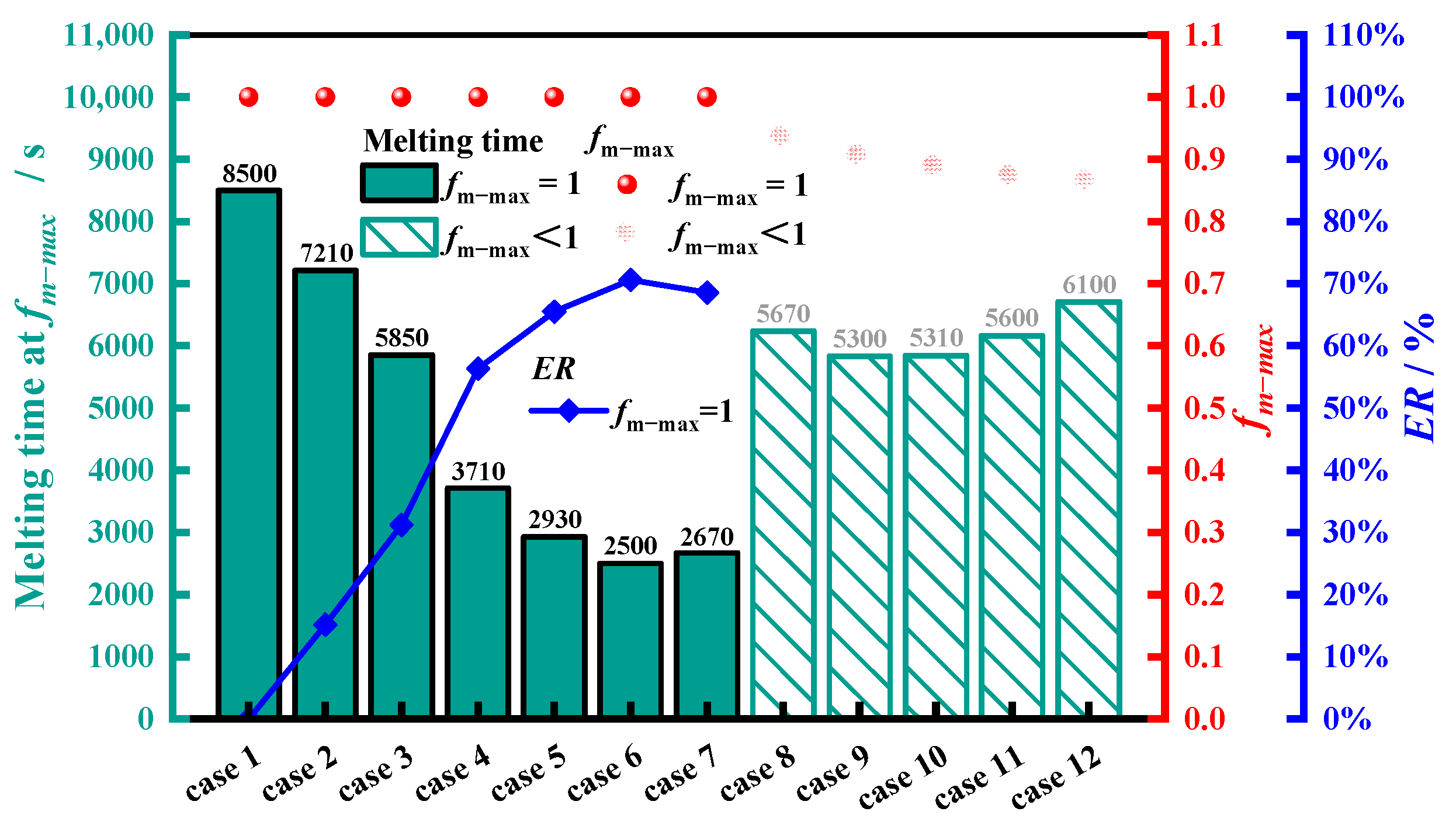
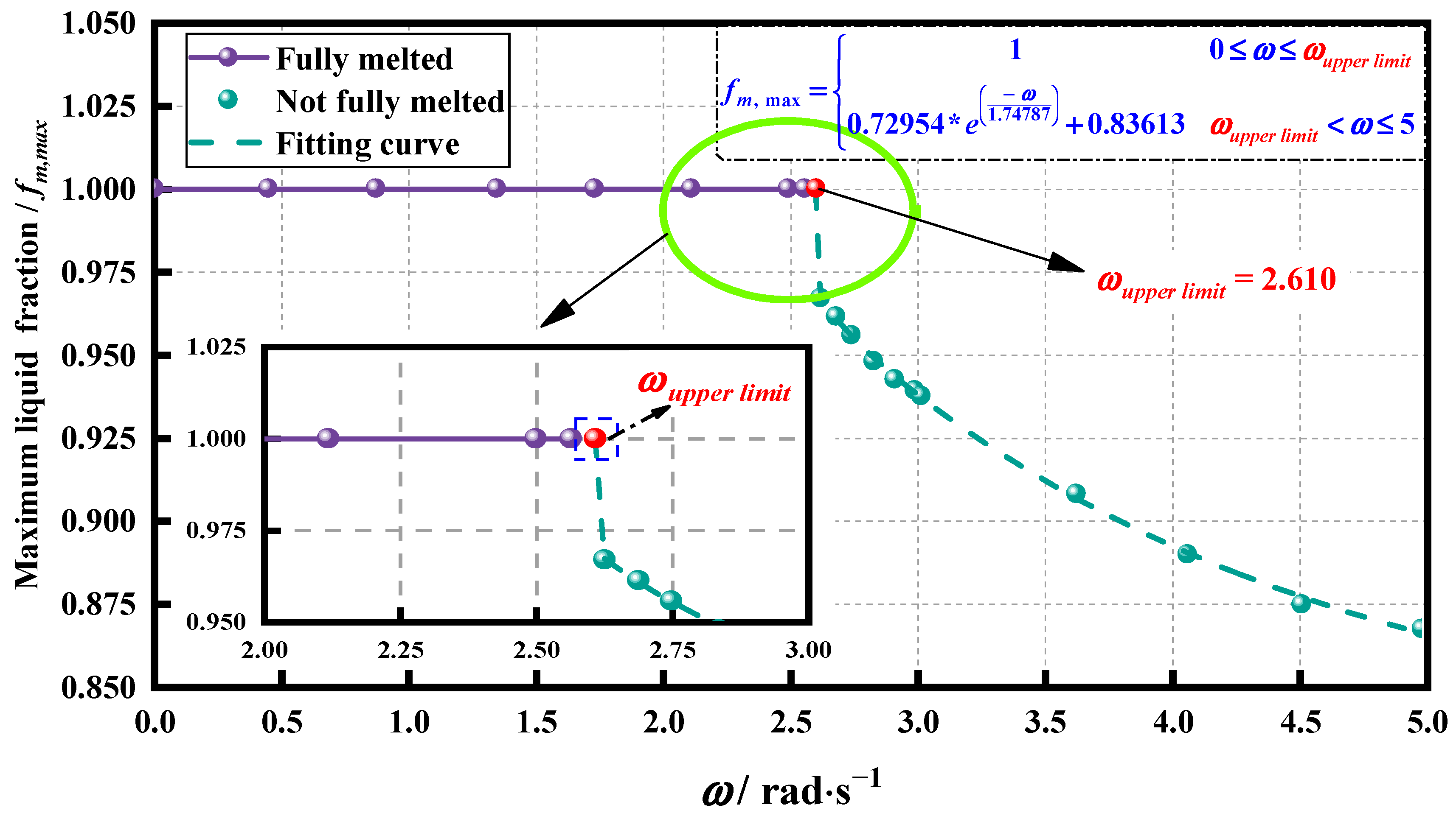
4.2. Determination of the Upper Limit of Rotation Speed

In Figure 4 and Figure 5, it was apparent that PCM cannot achieve complete melting when the rotation speed exceeded 2.5 rad·s−1. Therefore, it was presumed that an upper limit of speed existed between 2.5 rad·s−1 and 3.025 rad·s−1, enabling complete PCM melting. To investigate this, nine cases with rotational speeds between 2.5 and 3.025 were designed using Design-Expert. Numerical calculations yielded the maximum liquid phase fraction and melting time for each rotational speed, presented in Table 3. Figure 7 illustrated all the numerical simulation results of the two speed designs, where purple denoted complete melting and green indicated incomplete melting cases. For the cases unable to achieve complete melting, the fitting curve represented by the green dashed line was derived using mathematical methods. Furthermore, the relationship between rotation velocity and the maximum liquid phase fraction in the TES tube was established, as shown in Equation (13). Solving Equation (13) resulted in an upper speed of 2.610 rad·s−1. Subsequently, melting was simulated at this speed, yielding a maximum liquid phase fraction of one and a melting time of 4080 s.
f m , max = 1 0 ω ω upper   limit 0.72954 e ω 1.74787 + 0.83613 ω upper   limit < ω 5
where fm,max was maximum melting fraction of PCM in TES tubes.

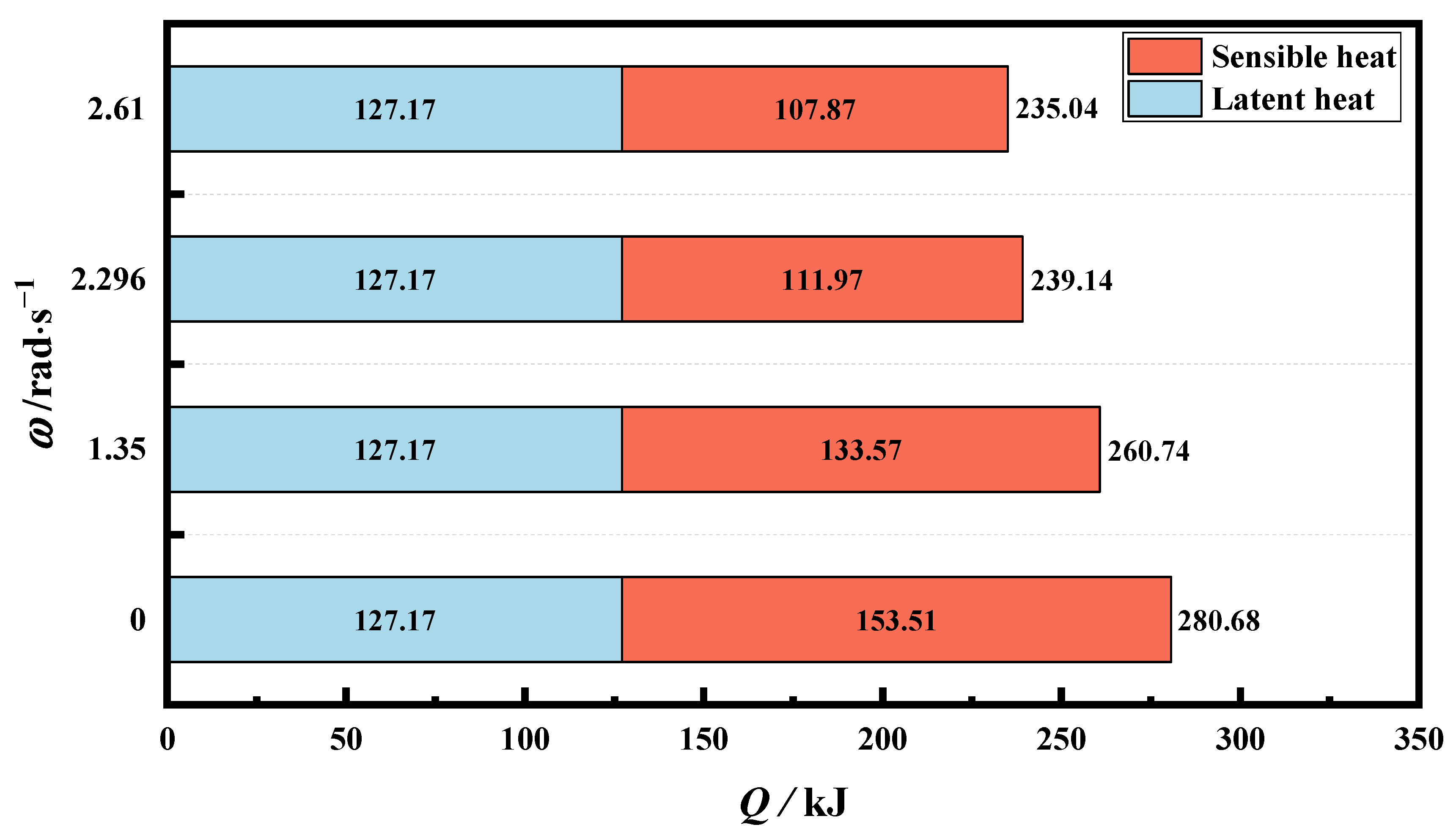
4.3. Determination and Analysis of Optimal Rotation Speed

4.3.1. Determination of Optimal Rotational Speed

As shown in Figure 4, Under the premise of complete melting, rotational drive significantly shortened melting time and enhanced thermal storage efficiency. However, the enhancement effect was not a monotonic function of rotational speed. The optimal rotational strategy was not achieved at the highest speed; rather, there existed a preferred rotational speed. To investigate the impact of this optimal rotational speed on melting performance, Design-Expert was employed for reconfiguring the experiment with rotational speed from 0 to 2.610 rad·s−1. Their melting time was as depicted in Table 4.

4.3.2. Melting Performance of PCM at Optimum Rotation Speed

In order to further explore the melting behavior of PCM in the TES tube at the optimal rotational speed, we selected rotational speeds of 0 rad·s−1, 1.350 rad·s−1, 2.296 rad·s−1 (optimal speed), and 2.610 rad·s−1 for in-depth discussion and analysis. Figure 8 depicted the solid–liquid front of the PCM at various melting times for the four rotation speeds. Similar to Figure 6, at the initial stage (at 500 s), the phase interface remained essentially consistent across the four rotation speeds due to dominant heat conduction as the heat transfer mechanism. For the melting time of 1000 s, a greater rotational speed resulted in a larger liquid phase region of the PCM. At 1500 s, the liquid phase region at speeds of 2.296 rad·s−1 and 2.610 rad·s−1 was notably larger than the other two cases. Moreover, at 2.610 rad·s−1, the outer wall of the finned tube demonstrated complete redness, while at 2.296 rad·s−1, the PCM near the outer wall was still partially solid. By 2000 s, the scenario at 2.296 rad·s−1 was reversed, with a significant increase in liquid PCM as compared to the case at 2.610 rad·s−1. Based on this, we can analyze the following: within the speed range that enabled complete PCM melting, during the first half of melting (approximately 1500 s), a higher rotation speed led to a larger liquid PCM region due to the generation of a stronger contact melting from larger centrifugal forces. As melting progressed, the liquid PCM gradually increased, while the solid phase was positioned in the middle region between fins, with more liquid PCM on the right than on the left. This resulted in a longer time to melt completely due to the larger radial centrifugal force impeding a better natural convection effect between the liquid area and solid area.
Figure 9 presents the temperature distribution of PCM at four rotation speeds. Comparable to the solid–liquid variable front distribution, employing the rotation strategy significantly enabled PCM to attain a larger area of high temperature across all four melting time points compared to a static tube. Additionally, a uniform temperature distribution of PCM in TES tubes indicates higher mass heat storage. Figure 10 exhibits the proportion of low temperature (25~55 °C), medium temperature (55~65 °C), and high temperature (65~70 °C) at the final melting moment in the four cases. A higher area ratio of medium-temperature PCM suggested effective heat storage, preventing local overheating, an ideal heat storage scenario for PCMs. Figure 10 represents that as the rotation speed increases, the area proportion of the high-temperature region significantly decreases, while the area of the low-temperature region substantially increases, signifying that the rotation strategy helped the PCM avoid local overheating but diminished the overall heat storage quality due to excessive rotation speed. Thus, the optimal rotation speed yielded a 73.1% area proportion of the medium-temperature PCM, the largest among the conditions. Moreover, in comparison to no rotation, the area proportion of high-temperature PCM at the optimal rotation speed decreased from 92.7% to 2.6%, marking a relative reduction of 97.2% in the risk of local overheating, indicating that the appropriate rotation speed effectively improves the thermal non-uniformity of PCM.
Figure 11 demonstrates the velocity distribution at four rotational speeds. Initially, it was observable that the rotation strategy accelerated the flow rate of the liquid phase PCM (approximately 100 times larger than the static tube). This denoted that the natural convection in the rotating tube was more intense, consequently strengthening the heat transfer in finned tube. Furthermore, at the 2000 s mark, the high-speed region of PCM in the TES tube at the optimal rotation speed surpasses that in other three cases. This suggested its natural convection was significantly robust, leading to a more pronounced heat transfer effect and achieving complete melting in a shorter time.
Figure 12 provides a comparison of the heat storage capacity of the PCM at different rotation speeds, as defined in Equation (14):
Q = ρ V L f m + c p ( T P C M T P C M , i n i t i a l )
where V, TPCM, and fm are defined as the volume, temperature, and liquid fraction of PCM in finned tubes; ρ, cp, and L represented the density, specific heat capacity, and latent heat.
At rotational speeds of 0 rad·s−1, 1.350 rad·s−1, 2.296 rad·s−1, and 2.610 rad·s−1, the total heat storage was 280.68 kJ, 260.74 kJ, 239.14 kJ, and 235.04 kJ, respectively. The full melting times for these cases were 8500 s, 3710 s, 2375 s, and 4070 s, resulting in heat storage rates of 0.03302 kJ/s, 0.07028 kJ/s, 0.10069 kJ/s, and 0.05775 kJ/s, respectively. Compared to the static tube, although the rotation strategy may marginally reduce the total heat storage of the PCM, the full melting time was significantly shortened, signifying improved heat storage efficiency. Specifically, the heat storage efficiency at the optimal rotation speed exhibited the greatest enhancement, with a 204.9% improvement relative to the static tube.

5. Conclusions

In this paper, melting performance of finned thermal energy storage with rotational actuation was investigated based a reliable numerical model. The influence of different rotation speeds (0~5 rad·s−1) on the melting behavior of the PCM was examined, including the transient melting characteristic, temperature evolution, flow transformation was comprehensively revealed, leading to the following conclusions:
(1)
For the finned tube investigated in this research, an appropriate rotation strategy could improve the heat transfer of the PCM. However, excessively high rotational speeds could result in the inability to achieve complete melting. When the rotation speed exceeded the upper limit rotational speed (as 2.610 rad·s−1), the PCM failed to achieve complete melting.
(2)
Under the condition of complete melting, the optimal rotational speed achieved the best performance of the finned latent heat phase-change unit, rather than the highest rotational speed. The preferred rotation speed (as 2.296 rad·s−1) effectively enhances the thermal non-uniformity of PCM in TES tubes and improves heat storage efficiency. Compared with the static tube, the risk of local overheating diminishes by 97.2%, while the heat storage efficiency at the optimal rotation speed increases by 204.9%.

Author Contributions

Conceptualization, Y.L., X.L., J.G. and X.Y.; Methodology, Y.L., X.M. and J.G.; Software, Y.L., X.M. and X.L.; Validation, X.M.; Formal analysis, Y.L., X.M., X.L. and J.G.; Investigation, Y.L., X.M. and X.L.; Data curation, Y.L., X.M. and X.L.; Writing—original draft, Y.L.; Writing—review & editing, X.Y.; Supervision, X.Y. All authors have read and agreed to the published version of the manuscript.

Funding

This research received no external funding.

Data Availability Statement

Dataset available on request from the authors.

Conflicts of Interest

Authors Yi Liu, Xiankun Meng and Xuanzhi Lv were employed by the company Xi’an Aeronautics Computing Technique Research Institute, AVIC. The remaining authors declare that the research was conducted in the absence of any commercial or financial relationships that could be construed as a potential conflict of interest.

Nomenclature

Abbreviation
FVM Finite   volume   method
LHTES Latent   Heat   Thermal   Energy   Storage
HTF Heat   transfer   fluid
PCM Phase   change   material
TES Thermal   energy   storage
Symbols
C E Inertial   coefficient
C p Specific   heat   capacity   J kg 1 K 1
f m Melting   fraction   of   PCM
f m , max Maximum   melting   fraction   of   PCM
g Acceleration   of   gravity   m s 2
k Thermal   conductivity   W m 1 K 1
L Latent   heat   kJ kg 1
p Pressure   Pa
T Temperature   ( )
t Time   s
V Flow   velocity   m s 1
u Superficial   velocity   at   x   direction   m s 1
v Superficial   velocity   at   y   direction   m s 1 ;   Average   velocity   m s 1
ω Rotational   speed   (   rad s 1 )
ω upper   limit Upper   limit   rotational   speed   (   rad s 1 )
ω optimal Optimal   rotation   speed   (   rad s 1 )
Greek symbols
ρ Density   kg m 3
γ Thermal   expansion   coefficient   K 1
μ Dynamic   viscosity   kg m 1 s 1
Subscript
l PCM   in   fluid   phase
f Paraffin
m Melted   PCM
s PCM   in   solid   phase

References

  1. Luo, D.; Yan, Y.; Chen, W.-H.; Yang, X.; Chen, H.; Cao, B.; Zhao, Y. A comprehensive hybrid transient CFD-thermal resistance model for automobile thermoelectric generators. Int. J. Heat Mass Transf. 2023, 211, 124203. [Google Scholar] [CrossRef]
  2. Xu, X.; Dong, Y.; Hu, Q.; Si, N.; Zhang, C. Electrochemical hydrogen storage materials: State-of-the-art and future perspectives. Energy Fuels 2024, 38, 7579–7613. [Google Scholar] [CrossRef]
  3. Chen, Y.; Meng, Y.; Zhang, J.; Xie, Y.; Guo, H.; He, M.; Shi, X.; Mei, Y.; Sheng, X.; Xie, D. Leakage proof, flame-retardant, and electromagnetic shield wood morphology genetic composite phase change materials for solar thermal energy harvesting. Nano-Micro Lett. 2024, 16, 196. [Google Scholar] [CrossRef] [PubMed]
  4. Öztürk, M.; Yüksel, C.; Çiftçi, E. Energy, exergy and sustainability analysis of a photovoltaic-thermal solar system with nano-enhancement and thermal energy storage integration. Process. Saf. Environ. Prot. 2024, 187, 593–604. [Google Scholar] [CrossRef]
  5. Vahidhosseini, S.M.; Rashidi, S.; Hsu, S.-H.; Yan, W.-M.; Rashidi, A. Integration of solar thermal collectors and heat pumps with thermal energy storage systems for building energy demand reduction: A comprehensive review. J. Energy Storage 2024, 95, 112568. [Google Scholar] [CrossRef]
  6. Alva, G.; Liu, L.; Huang, X.; Fang, G. Thermal energy storage materials and systems for solar energy applications. Renew. Sustain. Energy Rev. 2017, 68, 693–706. [Google Scholar] [CrossRef]
  7. Sánchez, A.; Zhang, Q.; Martín, M.; Vega, P. Towards a new renewable power system using energy storage: An economic and social analysis. Energy Convers. Manag. 2022, 252, 115056. [Google Scholar] [CrossRef]
  8. Yu, H.; Helland, H.; Yu, X.; Gundersen, T.; Sin, G. Optimal design and operation of an organic rankine cycle (ORC) system driven by solar energy with sensible thermal energy storage. Energy Convers. Manag. 2021, 244, 114494. [Google Scholar] [CrossRef]
  9. Jayathunga, D.; Karunathilake, H.; Narayana, M.; Witharana, S. Phase change material (PCM) candidates for latent heat thermal energy storage (LHTES) in concentrated solar power (CSP) based thermal applications—A review. Renew. Sustain. Energy Rev. 2024, 189, 113904. [Google Scholar] [CrossRef]
  10. Desage, L.; McCabe, E.; Vieira, A.P.; Humphries, T.D.; Paskevicius, M.; Buckley, C.E. Thermochemical batteries using metal carbonates: A review of heat storage and extraction. J. Energy Storage 2023, 71, 107901. [Google Scholar] [CrossRef]
  11. Du, Z.; Huang, X.; Li, Y.; Yang, X.; Li, M.-J. Design and study of metal foam parameters on whole melting-solidification cycle in phase change heat storage system. Int. J. Heat Fluid Flow 2024, 106, 109299. [Google Scholar] [CrossRef]
  12. Shen, J.; Chen, X.; Xu, X.; Kong, J.; Song, Z.; Wang, X.; Zhou, F. Thermal performance of a hybrid cooling plate integrated with microchannels and PCM. Appl. Therm. Eng. 2024, 236, 121917. [Google Scholar] [CrossRef]
  13. Khuda, M.A.; Yan, L.; Khalesi, J.; Sarunac, N.; Romero, C. Energy and exergy analysis of a laboratory-scale latent heat thermal energy storage (LTES) using salt-hydrate in a staggered tube arrangement. J. Energy Storage 2024, 87, 111320. [Google Scholar] [CrossRef]
  14. Righetti, G.; Zilio, C.; Guarda, D.; Feo, D.; Auerbach, M.; Butters, M.; Mancin, S. Experimental analysis of a commercial size bio-based latent thermal energy storage for air conditioning. J. Energy Storage 2023, 72, 108477. [Google Scholar] [CrossRef]
  15. Torbarina, F.; Lenic, K.; Trp, A.; Kirincic, M. Parametric analysis of system performance and cost of heating systems with heat pump and latent thermal energy storage. Appl. Therm. Eng. 2024, 252, 123717. [Google Scholar] [CrossRef]
  16. Rahi, M.R.; Ostadi, S.; Rahmani, A.; Dibaj, M.; Akrami, M. Studying the improvement of solar collector mechanism with phase change materials. Energies 2024, 17, 1432. [Google Scholar] [CrossRef]
  17. Tofani, K.; Tiari, S. Nano-enhanced phase change materials in latent heat thermal energy storage systems: A review. Energies 2021, 14, 3821. [Google Scholar] [CrossRef]
  18. Soares, N.; Matias, T.; Durães, L.; Simões, P.; Costa, J. Thermophysical characterization of paraffin-based PCMs for low temperature thermal energy storage applications for buildings. Energy 2023, 269, 126745. [Google Scholar] [CrossRef]
  19. Lalau, Y.; Rigal, S.; Bédécarrats, J.-P.; Haillot, D. Latent thermal energy storage system for heat recovery between 120 and 150 °C: Material Stability and Corrosion. Energies 2024, 17, 787. [Google Scholar] [CrossRef]
  20. Wołoszyn, J.; Szopa, K. Shell shape influence on latent heat thermal energy storage performance during melting and solidification. Energies 2023, 16, 7822. [Google Scholar] [CrossRef]
  21. Mat, S.; Al-Abidi, A.A.; Sopian, K.; Sulaiman, M.Y.; Mohammad, A.T. Enhance heat transfer for PCM melting in triplex tube with internal–external fins. Energy Convers. Manag. 2013, 74, 223–236. [Google Scholar] [CrossRef]
  22. Nguyen, T.P.; Ramadan, Z.; Hong, S.J.; Park, C.W. Effect of graphite fin on heat transfer enhancement of rectangular shell and tube latent heat storage. Int. J. Heat Mass Transf. 2022, 194, 123018. [Google Scholar] [CrossRef]
  23. Hassan, A.; Cotton, J.S. Investigation of the role of electrohydrodynamic forces on the heat transfer enhancement and solid extraction during melting of paraffin wax under constant temperature boundary conditions. Int. J. Heat Mass Transf. 2023, 204, 123831. [Google Scholar] [CrossRef]
  24. NematpourKeshteli, A.; Iasiello, M.; Langella, G.; Bianco, N. Increasing melting and solidification performances of a phase change material-based flat plate solar collector equipped with metal foams, nanoparticles, and wavy wall-Y-shaped surface. Energy Convers. Manag. 2023, 291, 117268. [Google Scholar] [CrossRef]
  25. Mebarek-Oudina, F.; Chabani, I. Review on nano enhanced pcms: Insight on nePCM Application in thermal management/storage systems. Energies 2023, 16, 1066. [Google Scholar] [CrossRef]
  26. Nair, A.M.; Wilson, C.; Kamkari, B.; Locke, J.; Huang, M.J.; Griffiths, P.; Hewitt, N.J. Advancing thermal performance in pcm-based energy storage: A comparative study with fins, expanded graphite, and combined configurations. Energy Convers. Manag. X 2024, 23, 100627. [Google Scholar] [CrossRef]
  27. Selvaraj, V.; Sreelekshmi, S.; Binoy, M.; George, S.; Senthilkumar, K. Investigation on the synergistic effect and thermal properties of poly-hydroxyethyl methacrylate encapsulated graphene quantum dot-paraffin hybrid nanofluid. Diam. Relat. Mater. 2024, 147, 111295. [Google Scholar] [CrossRef]
  28. Bian, Z.; Hou, F.; Chen, J.; Wang, H. Numerical analysis on the effect of graded porosity in closed-cell metal foams/PCM composites. Case Stud. Therm. Eng. 2024, 55, 104145. [Google Scholar] [CrossRef]
  29. Poyyamozhi, N.; Kumar, S.S.; Kumar, R.A.; Soundararajan, G. An investigation into enhancing energy storage capacity of solar ponds integrated with nanoparticles through PCM coupling and RSM optimization. Renew. Energy 2024, 221, 119733. [Google Scholar] [CrossRef]
  30. Boujelbene, M.; Mohammed, H.I.; Sultan, H.S.; Eisapour, M.; Chen, Z.; Mahdi, J.M.; Cairns, A.; Talebizadehsardari, P. A comparative study of twisted and straight fins in enhancing the melting and solidifying rates of PCM in horizontal double-tube heat exchangers. Int. Commun. Heat Mass Transf. 2024, 151, 107224. [Google Scholar] [CrossRef]
  31. Rashidi, S.; Bafekr, H.; Masoodi, R.; Languri, E.M. EHD in thermal energy systems—A review of the applications, modelling, and experiments. J. Electrost. 2017, 90, 1–14. [Google Scholar] [CrossRef]
  32. Rashid, F.L.; Rahbari, A.; Ibrahem, R.K.; Talebizadehsardari, P.; Basem, A.; Kaood, A.; Mohammed, H.I.; Abbas, M.H.; Al-Obaidi, M.A. Review of solidification and melting performance of phase change materials in the presence of magnetic field, rotation, tilt angle, and vibration. J. Energy Storage 2023, 67, 107501. [Google Scholar] [CrossRef]
  33. Rahmanian, S.; Shahsavar, A.; Rahmanian-Koushkaki, H.; Setareh, M.; Arıcı, M. Numerical feasibility study of improving the melting performance of horizontal and vertical double-pipe latent heat storage systems using ultrasonic field. J. Energy Storage 2023, 67, 107594. [Google Scholar] [CrossRef]
  34. Huang, X.; Li, F.; Li, Y.; Gao, X.; Yang, X.; Sundén, B. Investigation and optimization on melting performance of a triplex-tube heat storage tank by rotational mechanism. Int. J. Heat Mass Transf. 2023, 205, 123892. [Google Scholar] [CrossRef]
  35. Huang, X.; Li, F.; Lu, L.; Li, Z.; Yang, X.; Yan, J. Depth optimization of solidification properties of a latent heat energy storage unit under constant rotation mechanism. Energy Build. 2023, 290, 113099. [Google Scholar] [CrossRef]
  36. Anggraini, Y.; Yusuf, A.; Viridi, S.; Kurnia, D.; Wonorahardjo, S.; Sutjahja, I.M. Magnetic dopant and field effects on the heat discharge of organic PCM based lauric acid. Exp. Therm. Fluid Sci. 2024, 152, 111105. [Google Scholar] [CrossRef]
  37. Khanmohammadi, S.; Azimi, N.; Sharifzadeh, E.; Rahimi, M.; Azimi, P. An experimental study to improve cooling on a hot plate using phase change materials and high-frequency ultrasound. J. Energy Storage 2023, 72, 107930. [Google Scholar] [CrossRef]
  38. Kumar, A.; Maurya, A.; Siddiqui, I.H.; Alnaser, I.A.; Ashraf, I. Transient analysis of PCM discharging in a rotary triplex tube with wave-shaped fins. J. Energy Storage 2024, 79, 110178. [Google Scholar] [CrossRef]
  39. Fathi, M.I.; Mussa, M.A. The effect of whole system rotation on the thermal performance of a phase change energy storage. J. Energy Storage 2023, 68, 107732. [Google Scholar] [CrossRef]
  40. Guo, J.; Yang, B.; Li, Z.; Gao, X.; Xiao, T.; Yang, X.; He, Y.-L. Influence of rotation on heat absorption performance of solid–liquid phase change tank. Sol. Energy 2023, 264, 112008. [Google Scholar] [CrossRef]
  41. Abandani, M.H.; Ganji, D.D. Melting effect in triplex-tube thermal energy storage system using multiple PCMs-porous metal foam combination. J. Energy Storage 2021, 43, 103154. [Google Scholar] [CrossRef]
  42. Ji, C.; Qin, Z.; Low, Z.; Dubey, S.; Choo, F.H.; Duan, F. Non-uniform heat transfer suppression to enhance PCM melting by angled fins. Appl. Therm. Eng. 2018, 129, 269–279. [Google Scholar] [CrossRef]
  43. Huang, Y.; Liu, X. Charging and discharging enhancement of a vertical latent heat storage unit by fractal tree-shaped fins. Renew. Energy 2021, 174, 199–217. [Google Scholar] [CrossRef]
  44. Hu, X.; Gong, X. Pore-scale numerical simulation of the thermal performance for phase change material embedded in metal foam with cubic periodic cell structure. Appl. Therm. Eng. 2019, 151, 231–239. [Google Scholar] [CrossRef]
  45. Singh, V.K.; Patel, A. Effect of mushy zone constant on the melting of a solid-liquid PCM under hyper-gravity conditions. Int. Commun. Heat Mass Transf. 2022, 134, 105993. [Google Scholar] [CrossRef]
  46. Huang, X.; Yao, S.; Yang, X.; Zhou, R. Melting performance assessments on a triplex-tube thermal energy storage system: Optimization based on response surface method with natural convection. Renew. Energy 2022, 188, 890–910. [Google Scholar] [CrossRef]
  47. Soltani, H.; Soltani, M.; Karimi, H.; Nathwani, J. Heat transfer enhancement in latent heat thermal energy storage unit using a combination of fins and rotational mechanisms. Int. J. Heat Mass Transf. 2021, 179, 121667. [Google Scholar] [CrossRef]
  48. Fan, L.; Khodadadi, J.M. Thermal conductivity enhancement of phase change materials for thermal energy storage: A review. Renew. Sustain. Energy Rev. 2011, 15, 24–46. [Google Scholar] [CrossRef]
Figure 1. (a) Utilization of phase-change heat storage in low-carbon buildings; (b) physical model of rotational heat storage unit; (c) numerical calculation domain of rotational heat storage unit; (d) grid systems.
Energies 17 04209 g001
Figure 2. Independence verification: (a) grid test (24,498, 31,918, and 41,310), (b) time step test (0.05, 0.1, and 0.2).
Energies 17 04209 g002
Figure 3. Comparison about (a) liquid phase fraction and (b) average temperature of numerical models between the present study and reference work [47].
Energies 17 04209 g003
Figure 4. Maximum liquid fraction, melting time at maximum liquid fraction in 12 cases.
Energies 17 04209 g004
Figure 5. Curves of liquid fraction in 12 cases.
Energies 17 04209 g005
Figure 6. Front of phase transition of TES tube with different rotational speeds (ω = 0, 2.117, 3.025 rad·s−1) and with different melting times (at 500 s, 1000 s, 2000 s, 3500 s).
Energies 17 04209 g006
Figure 7. Determination of the upper limit of rotational speed.
Energies 17 04209 g007
Figure 8. Front of phase transition of TES tube with different rotational speeds (ω = 0, 1.350, 2.296, 2.610 rad·s−1) and with different melting times (at 500 s, 1000 s, 1500 s, 2000 s).
Energies 17 04209 g008
Figure 9. Temperature distribution of TES tube with different rotational speeds (ω = 0, 1.350, 2.296, 2.610 rad·s−1) and with different melting time (at 500 s, 1000 s, 1500 s, 2000 s).
Energies 17 04209 g009
Figure 10. The area ratio of low, medium, and high temperatures at different rotation speeds at the time of full melting.
Energies 17 04209 g010
Figure 11. Velocity distribution of TES tube with different rotational speeds (ω = 0, 1.350, 2.296, 2.610 rad·s−1) and with different melting times (at 500 s, 1000 s, 1500 s, 2000 s).
Energies 17 04209 g011
Figure 12. Comparison of heat storage capacity of PCM in TES tubes at different rotation speeds.
Energies 17 04209 g012
Table 1. Thermophysical details of the working medium.
Thermal PropertiesUnitParaffinCopper
Densitykg·m−3785.028920
Specific heat capacityJ·kg·K−12850380
Thermal conductivityW·m−1·K−10.1 (liquid)/0.2 (solid)398
Dynamic viscositykg·m−1·s−10.00365
Melting temperature°C50~55
Latent heatkJ·kg−1102.1
Thermal expansion coefficientK−10.000309
Table 2. Rotational speed for 12 cases.
Case123456789101112
ω/rad·s−100.4500.8751.3501.7372.1172.5003.0253.6364.0754.5255
Table 3. Melting time of the maximum liquid fraction at nine rotational speeds.
ω/rad·s−1Maximum Liquid FractionMelting Time/s
2.5001.00002670
2.5651.00003500
2.6280.96684040
2.6900.96114520
2.7500.95554810
2.8380.94764930
2.9200.94215110
3.0000.93885650
3.0250.93715670
Table 4. Melting time of finned thermal energy storage with rotational actuation.
Code ω / rad s 1 Full Melting Time/sCode ω / rad s 1 Full Melting Time/s
10850082.1172500
20.450721092.2272410
30.8755850102.2962375
41.3503710112.3202400
51.6313090122.3522440
61.7372930132.5002670
71.9562680142.6104070
Disclaimer/Publisher’s Note: The statements, opinions and data contained in all publications are solely those of the individual author(s) and contributor(s) and not of MDPI and/or the editor(s). MDPI and/or the editor(s) disclaim responsibility for any injury to people or property resulting from any ideas, methods, instructions or products referred to in the content.

