Abstract
Construction of relay protections of electrical installations without the use of bulky metal- and insulation-intensive measuring current transformers (CTs) was repeatedly discussed at Conferences of the International Council on Large Electric Systems (CIGRE) as a challenge for the electric power industry. In the article, the authors present resource-saving reed switch current protection for 6–10-kV electrical installations connected to switchgear cells, which is an alternative to traditional protections. The scientific novelty of the work lies in (a) reed switch protection design on the basis of measuring the magnetic induction in different modes and at different points inside a cell, and we prove that inductance values are sufficient to detect phase short-circuits in electrical installations fed from this cell and derive the dependence of the induction on the position of an inductance coil inside the cell; (b) proven possibility of using the simplest formula of the Biot–Savart law for the calculations if the experimentally obtained coefficients are introduced into it; (c) development of a technique for calculating the parameters of the overcurrent protection based on reed switches. Experimental results are presented in graphical form and clearly show the points of EMS maxima and minima. Settings for resource-saving current protection are selected and a feasibility study of the effectiveness of resource-saving overcurrent protection is carried out. A technical and economical assessment of the efficiency of the suggested overcurrent protection is conducted.
1. Introduction
As is known microprocessor relay protection devices are widely used in the energy industry. The reliability of these protections is not higher than that of electromechanical or semiconductor protection systems [1,2,3,4]. The issue of resource-saving in the electric power industry has been repeatedly raised by the International Council on Large Electric Systems (CIGRE). It remains relevant for relay protection of electrical installations because of the common use of expensive, heavy and large and metal-intensive measuring current transformers (CTs) with metal cores [5,6,7,8]. Abandoning the use of traditional measuring current transformers with metal cores contributes to significant savings (conservation) of electrical and thermal energy required for their production, and this contributes to the resource-saving of the materials used. The creation of resource-saving relay protection devices against short circuits in electrical installations without the use of measuring current transformers (CT) was started in the 1960s [9,10,11,12,13,14,15,16,17,18,19] and remains a topical problem today. In addition, abandoning the use of measuring current transformers improves the reliability of relay protection systems. As an alternative to traditional relay protection systems, new devices are created on different elemental bases, for example, magnetic field sensors, such as magnetotransistors [20], magnetodiodes [20], magnetoresistors [21,22], Hall sensors [22], Rogowski coils [23,24] and reed switches [25]. Reed switches have several advantages over other magnetosensitive elements [26,27,28].
Principles of construction of reed switch current protections have been already developed. However, these principles cannot always be used without additional research because of the variety of arrangements of, for example, current-carrying busbars in switchgear cells supplying electrical installations to be protected [29,30,31]. Since reed switches are fixed inside a cell and respond to the sum of magnetic fields produced by currents in one of its current-carrying busbars opposite which it is mounted and in the current-carrying busbars of neighboring phases of this and neighboring cells, which are sources of interference, there is a need to study magnetic fields at the points where reed switches are located.
In this work, an attempt is made to solve these problems. We experimentally study three-phase, two-phase and single-phase short circuits in switchgear cells. To detect magnetic fields from current-carrying busbars, we measure the coil values of an intermediate MKU-48 type relay [32] without an internal metal core; they act as magnetic field sensors. Current protection is designed on the basis of reed switches as an alternative to traditional protections for 6–10-kV electrical installations connected to switchgear cells. Resource saving of this protection is provided by cost and weight and size parameters of reed switches, since these elements are an order of magnitude cheaper, lighter and smaller than current transformers [8,27]. The selection of settings for the suggested protection can be performed in the same way as for traditional protections.
The aim of this experimental research is the development of a resource-saving current protection based on inductive coils and reed switches without the use of traditional measuring current transformers with metal cores for protecting electrical installations connected to switchgear cells of 6–10 kV voltage. The choice in favor of such protections is because traditional protections use expensive, heavy, and metal-intensive measuring current transformers. To achieve this aim, it is necessary to perform laboratory experiments with a switchgear cell. The efficiency of the presented resource-saving protection is confirmed by the calculation of protection trip settings, checking its sensitivity coefficient, and the comparison of this protection with traditional protections.
The work includes the following sections: the Materials and Methods, which presents the means used to achieve the aim; the Experimental Section, which describes the performed experiments; the Results, which considers the results of all performed experiments including the graphical form, calculation of the field damping coefficient, correction factor, and phase coefficient necessary to select the protection settings, the use of reed switches in the relay protection, and an example of a Resource-Saving Reed Switch Current Protection; the Conclusions; the Patents (developed); Appendix A, which provides an example of the selection of settings for the proposed overcurrent protection; Appendix B, with the technical and economical confirmation of the efficiency of the resource-saving overcurrent protection; and the References, with the list of sources used.
2. Materials and Methods
In the suggested reed switch overcurrent protection, a reed switch simultaneously acts as a current sensor and a measuring unit and responds to the magnetic field produced by currents in the phases of a protected electrical installation. For example, a reed switch actuates (closes its previously open contacts) if the magnetic induction acting on its contacts attains an actuating value, i.e., the so-called magnetomotive force of the reed switch arises, which is estimated at the factory with the use of a control winding of a certain length wound on the reed switch. To respond to the magnetic field, a reed switch is mounted close to the current-carrying busbars at a minimum permissible distance [27,33,34]. To attain the aim of the work, fundamental principles of the theoretical foundations of electrical engineering and relay protection, fundamentals of the theory of electromagnetic transient processes and the design of mechanisms and machines, and laboratory experiments were used. The work was carried out in accordance with the scientific directions of research committee B5 “Relay Protection and Automation” of the International Council on Large Electric Systems (CIGRE), which unites scientists and specialists in the field of electrical power systems throughout European and CIS countries.
3. Experimental Section
To estimate the effects of magnetic fields and interference, an experimental setup was assembled and experiments were performed inside KRU-2 cell (1) [35]; K-63 cell (2) [36] was placed to the right of cell 1 at a distance of 44 cm. For a better understanding of the composition of the experimental setup, Figure 1c shows its structural diagram. Cells 1 and 2 were placed in a laboratory room with a concrete floor (Figure 1 and Figure 2). Bearing wall (3) was on the left side of cell 1, and brick partition (4) was behind this cell at a distance of 35 cm. The width of cell 1 was 90 cm and the wall thickness was 0.3 cm. The experimental setup (Figure 1a) included the following: three-phase switch (5) with the rated current I = 100 A and alternating voltage U = 380 V; three-phase voltage regulator (7), which is connected to switch (5) by first cable (6).
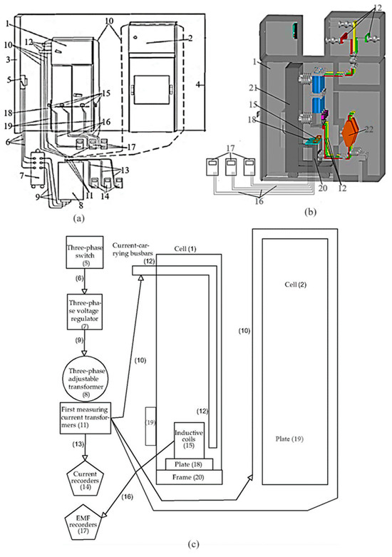
Figure 1.
(a) Experimental setup and scheme of estimating EMF values inside cell 1; (b) side view of cell 1; (c) structural diagram of the experimental setup.
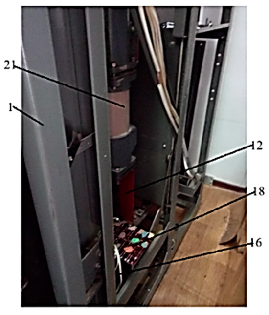
Figure 2.
Cell 1 with a plate (18) with fixed ICs (15) (side-right view).
The primary winding of a three-phase load transformer (8), which supplied three-phase sinusoidal alternating current, was connected by cable (9) to the three-phase voltage stabilizer (7), which was required to supply three-phase sinusoidal alternating voltage. The secondary winding of the three-phase load transformer (8) was connected to three current-carrying busbars (12) of cell 1 by second cables (10) passed through the windows of current transformers (11). Current-carrying busbars (12) were centered at points 68 cm (phase A), 45 cm (phase B), and 22 cm (phase C) relative to the right wall of cell 1. A three-phase load transformer (8) was mounted opposite the front wall of cell 1, and second cables (10) were laid on both the left and right sides of cell 1 and around cell 2 (shown by the dashed line in Figure 1). This connection enables the detection of magnetic fields inside cell 1 and their effect on the measured values of magnetic induction inside cell 1. Current recorders (14) were connected to the secondary windings of current transformers (11) using wires (13).
To estimate the magnetic field values inside cell 1, three identical inductive coils (ICs) (15) without a metal core were used. They were windings of an intermediate MKU-48 relay and functioned as magnetic field sensors (actuators of the resource-saving current protection). Inductive coils (15) were connected by wires (16) to EMF recorders (17) [32]. Fluke 87V multimeters were used as current and EMF recorders. To move and fix ICs (15) inside cell 1, the first textolite plate (18) of 90 × 18 × 0.5 cm in size with 1 cm graduation was used. The second plate (19) was fixed on the outside of cell 1. Inductive coils (15) were mounted on the first plate (18) in the plane of the busbars (12) and in three rows spaced 12, 18, and 24 cm apart. The EMF values were measured at 21 points on the first plate (18) and then converted into magnetic induction values.
Plates (18 and 19) with ICs (15) mounted on them were arranged as follows: plate (18) was horizontally fixed on the frame (20) of the circuit breaker (21) inside cell 1 in three vertical positions: 0, 6, and 12 cm (Figure 1 and Figure 2). Plate 19 was flat against the outer sides of the left and right walls of cell 1. The distance and, accordingly, the points where ICs (15) were fixed on the first plate (18) were measured from the right to the left wall of the cell and upward from the plane of current-carrying busbars (12) on a vertically arranged second plate (19).
Inputs L1 of the primary winding of TPL-10-300 22 measuring (Sverdlovsk Plant of Current Transformers, Sverdlovsk, Russia) current transformers [8] were connected to current-carrying busbars (12). Terminals L2 of this primary winding were three-phase short-circuited. The secondary winding of current transformers (22) was also short-circuited during the experiments, because if it is non-shorted (connected), then the supplied current can induce high EMF in it and burn it (since the insulation is insufficient for high EMF values), thus damaging the current transformer. During experiments, a three-phase voltage regulator (7), a load transformer (8), and the housings of cells 1 and 2 were grounded for safety.
To estimate EMF values inside cell 1 during all experiments and for all short circuit types, a three-phase switch (5) was first turned on (see Figure 1a) and an alternating current was supplied to the busbars (12) from the three-phase load transformer (8) using the three-phase voltage regulator (7); the current strength in the busbars (12) was controlled by readings of current recorders (14). This current induced the EMF at the terminals of ICs (15), which was measured and recorded by EMF recorders (17). All experiments were performed in laboratory conditions.
The first experiment: AC flows through three busbars. In this experiment, EMF values are measured at terminals of ICs (15) fixed on a plate (19) at a distance of 12 cm from the plane of busbars (12) starting from the current I = 100 A and up to I = 600 A and recorded by EMF recorders (17). Inductive coils (15) are moved from point 0 cm to point 90 cm while permanently recording EMF values. An alternating current is simultaneously supplied from three phases of the load transformer (7) to three busbars (12) of cell 1. The current is supplied to the input of the busbars (12) and flows through them and through TPL-10-300 current transformers (22) connected to the ends of the busbars (12). The ends of the primary windings of the TPL-10-300 current transformers are three-phase short-circuited to simulate a three-phase SC. The secondary windings of current transformers (22) are also short-circuited to prevent damage. The current is increased by 100 A up to 600 A at each subsequent IC point and magnetic field parameters are recorded at each current value. An alternating current of 600 A is the maximal output of the load transformer (8). After measuring the EMF of the magnetic field from the outer sides of cell 1, ICs (15) are fixed at a distance of 18 and then 24 cm from the plane of the busbars (12) on the plate (19) (see Figure 1a), and EMF values are again measured and recorded. The procedure for measuring and recording the EMF is the same for points spaced 12, 18, and 24 cm apart from the plane of current-carrying busbars (12) and for the first, second, and third positions of the first plate (18).
The second experiment: AC flows through two busbars. In this experiment, a two-phase SC is simulated with the use of the same setup, equipment, instruments, ICs, and technique as in the previous experiment (see Figure 1 and Figure 2). Alternating current is simultaneously and alternately supplied from two phases of load transformer (8) to two current-carrying busbars (12) of cell 1. Alternating current is supplied to the input of these busbars (12) and flows through them and through TPL-10-300 current transformers (22) connected to the ends of busbars (12). The ends of the primary windings of the TPL-10-300 current transformers are two-phase short-circuited to simulate a two-phase short circuit. The secondary windings of these current transformers are also short-circuited to prevent damage.
The third experiment: AC flows through one busbar. In this experiment, a single-phase SC is simulated with the use of the same setup, equipment, instruments, ICs, and technique as in the previous experiments (see Figure 1 and Figure 2). Alternating current is supplied from one of the phases of the load transformer (8) to each current-carrying busbar (12) of cell 1 in series. The current is supplied to the input of busbars (12) and flows through them and the TPL-10-300 current transformer (22) connected to the end of the busbar (12). The secondary windings of current transformers (22) are also short-circuited to prevent their internal damage. The end of the power cable coming from the load transformer (8) is connected to the input of the busbar (12). One end of the second power cable is connected to the output of the primary winding of the current transformer (22), and the other end of the cable is connected to the same phase of the load transformer (8).
4. Results
The results of all the performed experiments are shown in the figures. The results of three experiments on detecting points of maximal EMF inside cell 1, where reed switches (trip relays) of the suggested overcurrent protection are to be fixed, are presented in the form of plots.
Figure 3, Figure 4, Figure 5 and Figure 6 show the EMF as a function of the magnitude of alternating current supplied by a three-phase load transformer (8) to the busbars (12) and the points where the ICs (15) are fixed on the plate (18) during a three-phase short circuit for different positions (horizontal and vertical) of the plate (18) and three rows of the ICs with and without the right wall of cell 1. In these figures, the length of the plate (18) is plotted along the abscissa. As can be seen, the EMF values are maximum when the ICs (15) are in the first row on the plate (18), since they are closer to the current-carrying busbars (12) in this case. The EMF values are lower when the ICs (15) are fixed in the second row and are minimal when the ICs are in the third row because of the greater distance from the busbars (12) (18 and 24 cm, respectively).
EMF during a two-phase short circuit inside cell 1 is plotted in Figure 7a–c versus the supplied alternating current and the points of ICs (15) in the first row and a horizontal position of the first plate (18) in the presence of the right wall of cell 1. The EMF values are maximal at the following points: 45 and 68 cm in the case of a short circuit between phases A and B; 24 and 68 cm in the case of a short circuit between phases A and C; 22 and 47 cm in the case of a short circuit between phases B and C at a distance of 12 cm from the two corresponding busbars. Analysis of EMF values for three two-phase SC types (between phases A and B, A and C, and B and C) shows the EMF to be maximal in the case of a short circuit between phases A and C.
Figure 8 shows the measured EMF values in the case of a ground fault in phases A, B, and C in the presence of the right wall of cell 1 and when plate (18) is in a horizontal position and ICs (15) are in the first row. Knowing the EMF in the case of a single-phase short circuit inside cell 1, it was plotted as a function of the supplied alternating current and the points of ICs (15). The EMF values are maximal at the following points: 68 and 86 cm in the case of a ground fault in phase A; 47 and 86 cm in the case of a ground fault in phase B; 22 and 86 cm in the case of a ground fault in phase C. These values were recorded when ICs (15) were in the first row on the plate (18) at a distance of 12 cm from each corresponding busbar (12).
In these figures, the length of the plate (18), in cm, is plotted along the abscissa, and the EMF values, in mV, are plotted along the ordinate.
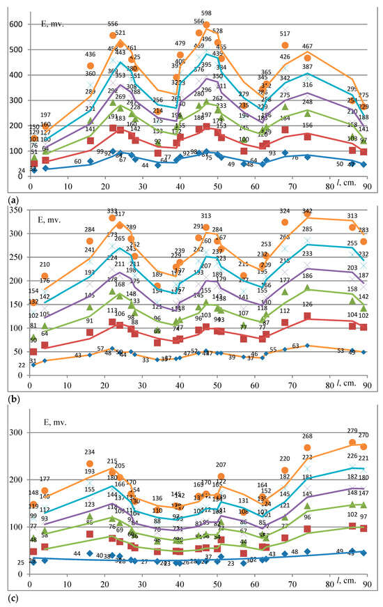
Figure 3.
EMF as a function of the supplied current in the case of a three-phase short circuit in the presence of the right wall of cell 1: (a) the first, (b) the second, and (c) the third row on the plate (18) which is in the horizontal position.
Figure 3 shows the dependence of EMF on the supplied current and the points of ICs (15) during a three-phase short circuit when plate (18) is at the first position inside cell 1 and the ICs are in the (a) first, (b) second, and (c) third row on the plate (18). The EMF curve is wave-like with maxima and minima. The EMF values are maximal when the ICs (15) are in the first row on the plate (18). This is explained by the fact that the ICs (15) being fixed in this position are closer to the current-carrying busbars (12). When the ICs (15) are in the other two rows on the plate (18), the EMF values are lower because the ICs (15) are further from the busbars (12), that is, at a distance of 18 and 24 cm from them. The figure shows the wave-like (three main waves) behavior of EMF, with maxima and minima.
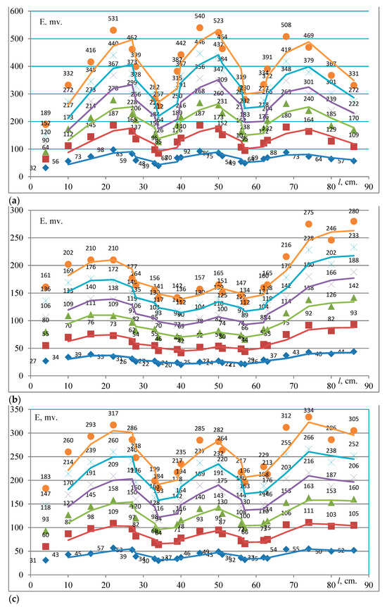
Figure 4.
EMF as a function of the supplied current in the case of a three-phase short circuit in the absence of the right wall of cell 1: (a) the first, (b) the second and (c) the third row on the plate (18) which is in the horizontal position.
Figure 4 shows the wave-like character of variations in the EMF versus the supplied current and the points of the ICs (15). The EMF is maximal when the ICs (15) are in the first row on the plate (18), that is, at a distance of 12 cm from current-carrying busbars (12), because the ICs are closer to the busbars (12) in this row than in the other two rows, at distances of 18 and 24 cm from busbars (12). The EMF values in Figure 4 are lower than in Figure 3. This is explained by the fact that the total value of the EMF inside cell 1 is lower in the absence of the right wall of cell 1 than with this wall.
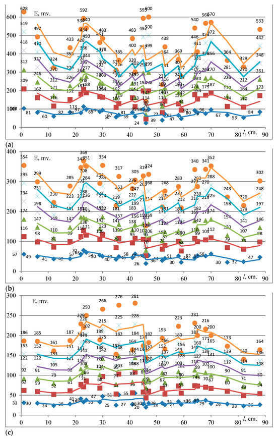
Figure 5.
EMF as a function of the supplied current in the case of a three-phase short circuit in the presence of the right wall of cell 1: (a) the first, (b) the second and (c) the third row on the plate (18) which is in vertical position 60 mm.
Figure 5 shows the sawtooth (several waves) dependence of the EMF on the supplied current and the points of the ICs (15), with maxima and minima. The EMF is maximal when the ICs (15) are in the first row on the plate (18), that is, at a distance of 12 cm from the current-carrying busbars (12). This is explained by the fact that the ICs are closer to the current-carrying busbars in this case than in the other two rows, at distances of 18 and 24 cm from the busbars (12). In comparison with Figure 3 and Figure 4, EMF maxima are similar at some points and higher at others. This is because at an altitude of 6 cm, the ICs are located closer to the internal metal parts of cell 1, which creates additional (magnetic field) interference detected by the ICs (15).
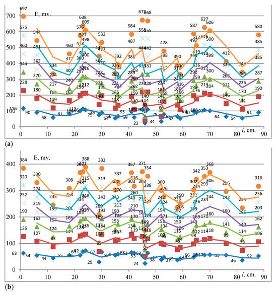
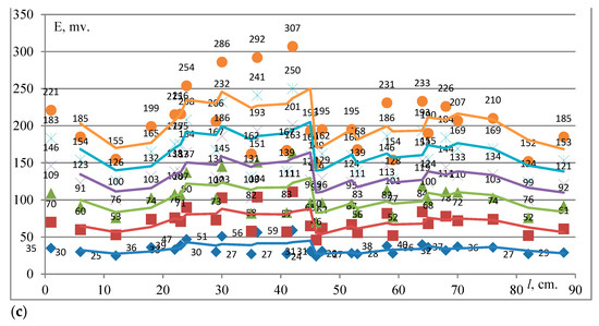
Figure 6.
EMF as a function of the supplied current in the case of a three-phase short circuit in the presence of the right wall of cell 1: (a) the first, (b) the second and (c) the third row on the plate (18) which is in vertical position 120 mm.
The variation in EMF in Figure 6 has a sawtooth shape, with maxima and minima, like in Figure 5. The EMF is also maximal when the ICs (15) are in the first row on the plate (18), that is, at a distance of 12 cm from the current-carrying busbars (12), for the same reasons as in Figure 5. There are more EMF maxima in Figure 6 than in Figure 6, especially in the first row on plate (18). This is because at an altitude of 12 cm, the ICs are even closer to the internal metal parts of cell 1, which creates additional magnetic (magnetic fields) interference detected by ICs (15).
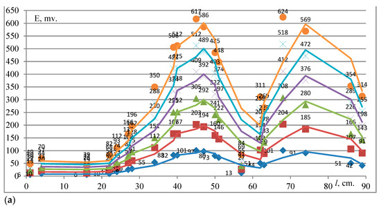
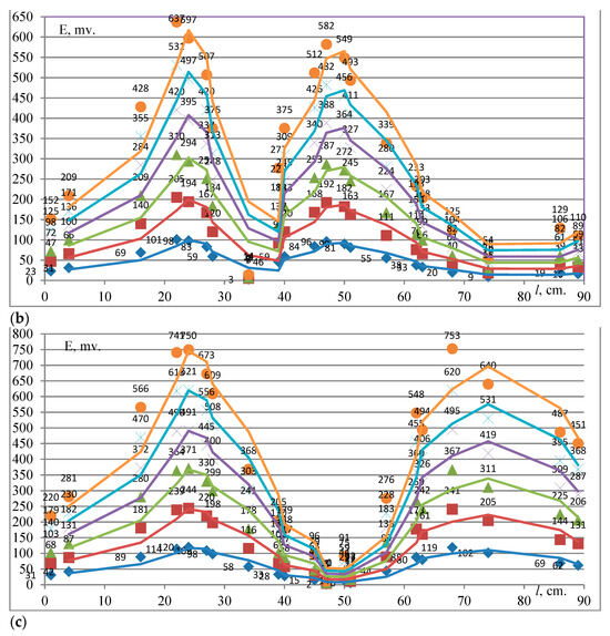
Figure 7.
EMF as a function of the supplied current in the case of a two-phase short circuit between two phases: (a) A and B; (b) A and C; (c) B and C in the presence of the right wall of cell 1 when the plate (18) is in the horizontal position and the ICs (15) are fixed in the first row.
Figure 7 shows the wave-like (two large waves) dependence of the EMF, with maxima and minima. The EMF values are maximal in the case of a two-phase short circuit between phases A and C. This is due to the fact that the radius of propagation of magnetic waves from buses A and C includes magnetic fields not only from the current-carrying busbars but also reflected from the walls of the casing of cell 1. These buses are located on two sides, that is, closer to the side walls of cell 1 than bus B. Bus B is located in the very middle of the casing of cell 1.
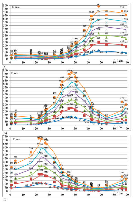
Figure 8.
EMF as a function of the supplied current in the case of a ground fault in (a) phase A, (b) phase B and (c) phase C in the presence of the right wall at cell 1 when the plate (18) is in the horizontal position and the ICs (15) are fixed in the first row.
Figure 8 shows the measured EMF values in the case of ground faults in phases A, B, and C, when ICs (15) are fixed in the first row on plate (18). The EMF is maximal at the following points: 68 and 86 cm in the case of a ground fault in phase A, 47 and 86 cm in the case of a ground fault in phase B, and 22 and 86 cm in the case of a ground fault in phase C. The EMF variation is wave-like (one large wave) in character, with maxima and minima. The EMF values in the case of ground fault are the highest in comparison with other short circuit types (three- and two-phase). This is explained by the absence of mutual damping of the magnetic fields from nearby current-carrying busbars and by the internal distribution of the magnetic field inside cell 1.
The determination of the field damping coefficient , correction factor and phase coefficient for the calculation of the selection of resource-saving protection settings is presented below.
4.1. Field Damping Coefficient
By means of this coefficient, we have studied how the right or left wall of the body of cell 1 decreases the magnetic induction (measuring the EMF and recalculating it into magnetic induction) on the inner and outer sides of the wall under the maximal current (600 A) produced by the load transformer. Figure 1a and Figure 9 show the layout of cable 10 routing around cell 2, which simulates an external short circuit current in cell 1 from an electrical installation connected to cell 2. In this case, two ICs (15) are mounted on the first plate (18) at its first position and at a distance of 12 cm from the plane of the current-carrying busbars (12) inside cell 1, in its two endpoints 1 and 90 cm, which are maximally close to the neighboring cells. The third IC is fixed on the second plate (19) and is mounted on the outside of the right and left walls of cell 1 at a distance of 12 cm from the plane of the current-carrying busbars (12) of cell 1. All three ICs (15) are placed at the same level relative to the floor.
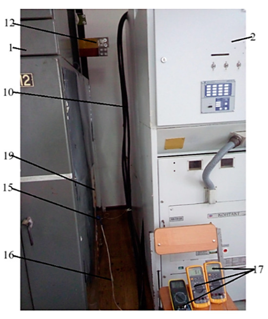
Figure 9.
Experimental scheme for simulating external short-circuit current in cell 1 from an electrical installation connected to cell 2.
The induction values measured inside cell 1 are compared with the magnetic field induction values at the outer sides of this cell. On the basis of the results, the coefficients of field damping by the left () and right walls () of cell 1 are calculated as:
where in and are the values of magnetic induction, T, measured at points 1 and 90 cm on the inner () and at points −0.3 and 90.3 cm on the outer () sides of the right and left walls of cell 1:
4.2. Correction Factor
The correction factor enables taking into account the errors caused by alternating current flowing through busbars and by magnetic field distortion. For this purpose, we use the formula of the Biot–Savart law. According to this law, a reed switch actuates at the magnetic induction defined as [6,37]:
where , and are the minima of the current in a current-carrying busbar, magnetic field strength and induction, at which a reed switch actuates; is the permeability of air.
The experiment was performed with first plate (18) in the first position. To find the correction factor, the induction measured at all measuring points on plate (18) is compared with the magnetic field inductions calculated by the Biot–Savart law at the same points:
The magnetic field induction is calculated by the formula
where I is the current supplied by the load transformer to current-carrying busbars, A; is the permeability of air; h is the distance between an inductance coil and the current-carrying busbars, cm.
The magnetic field induction is experimentally determined by the formula [37]:
where is the EMF output from IC 15 during the experiments; ω and S are the number of turns and cross-section area of the inductance coil; f is the industrial frequency.
Taking into account the maximal magnetic inductions at the centers of axes of the current-carrying busbars of cell 1 in the case where the current I = 200, 400 and 600 A flows through a current-carrying busbar of phase A (point 68 cm), the correction factor is:
The correction factor is calculated in a similar way in the cases where the current flows through three and two busbars of cell 1.
4.3. Phase Coefficient
This coefficient is introduced because each reed switch mounted opposite a proper phase is affected by magnetic inductions from both this phase and the other two phases when the current is flowing through three, two and one phases. In this case, the EMF values experimentally determined by the ICs (15) are also converted into magnetic induction values by Equation (1).
The purpose is to estimate how many times the induction of the current flowing in one busbar differs from the inductions , when the current flows through the two and three other busbars of cell 1.
Based on the induction values at different values of current through three, two and one busbars (phase A, point 68 cm), the phase coefficient is calculated by the formula
When the current I = 200, 400 and 600 A flows through one (A) and two (AB; AC) busbars of cell 1, the phase coefficients are
When the current I = 200, 400 and 600 A flows through one (A) and three (ABC) busbars,
The phase coefficient is calculated in a similar way when current flows through three, two, and two single B and C busbars. When the current flows through one busbar, the phase coefficient.
4.4. Use of Reed Switches in Relay Protection
Measuring current transformers have been used as the main transducers for relay protection and measurement devices for many years. They have such disadvantages as high errors, voltages that appear when the winding in the secondary circuit breaks, size, weight, and expensive materials. Due to these disadvantages, the International Council on Large Energy Systems (CIGRE) has repeatedly raised the question, for example, about a need to use or develop sensors that could become an alternative to traditional measuring current transformers.
Reed switches can help to solve this problem. They are commonly used in technology, are promising [27], and have important advantages for relay protection. Thus, reed switches can simultaneously function as a measuring current transformer, an actuator, and an analog-to-digital converter; they do not require amplifiers to transmit a signal, and the transmission is carried out through control, but not measuring circuits; and there is no need in devices which reduce the temperature effect.
Reed switches are mounted at specified points at a safe [33] distance h from the current-carrying busbar of the electrical installation and actuate (close or switch contacts 1 (Figure 10), fixed in glass tube 2 0.7 to 5 cm long) for 0.1–3 ms under the action of a magnetic field produced by the current in the busbar.
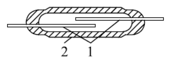
Figure 10.
Reed witch design: contacts (1) and glass tube (2).
A reed switch current protection consists of simple accessible elements and is easily assembled. It consists (Figure 11) of a reed switch (1), pulse stretcher (2), time relay (3), and actuator (4) [6].

Figure 11.
Block diagram of a reed switch overcurrent protection.
When a protection is based on reed switches, the scheme coefficient and transformation coefficient are not used, but the protection operation current Iprot.oper and return current Ireturn remain [6]. Timing characteristics and sensitivity coefficient are applied in the same way as for overcurrent protections based on measuring current transformers with metal cores. The arrangement of a reed switch at a safe distance h from, for example, phase A in the plane of its cross section is shown in Figure 12 [6]
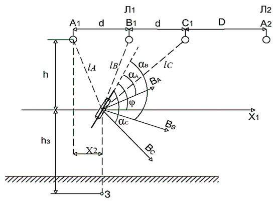
Figure 12.
Arrangement of a reed switch near current-carrying busbars of an electrical installation: , , and are the angles between the longitudinal axis of the reed switch and vectors , , and of the magnetic induction of phases A, B, and C; , , and are the distances between the current-carrying busbars to the center of gravity of the reed switch; is the distance between two verticals, one of which passes through phase A and another passes through the center of gravity of the reed switch; φ is the angle between the longitudinal axis of the reed switch and the horizontal plane ; () is the distance from the busbar (earth) to the reed switch; d is the interphase (between their axes) space; D is the distance between two power lines and .
An example of selecting settings for the suggested overcurrent protection is described in Appendix A. Appendix B technically and economically substantiates the efficiency of the resource-saving overcurrent protection.
As an example of the implementation of resource-saving reed current protection, the following is an example of “Resource saving Motor Current Protection with Remote Setpoint Selection”.
5. Resource Saving Electric Motor Current Protection with Remote Setpoint Selection
Current protection with remote setpoint selection, presented in the form of a device in its composition consists of reed switches (1) (Figure 13a), which are mounted on the plate (2) and are located at different angles to the plane of the cross section of the current-carrying busbar (3) of any cell of the complete switchgear. The leads of the contacts (4) of reed switches (1) are connected to the time-zapper (5). The plate (2) is fixed to the first end of the support post (6) and is located opposite the current-carrying busbar (3) at a safe distance from it. The other end of the support stand (6) is fixed inside the container (7) with the help of the sleeve (8) fixed to the wall of the container (7). Inside the container (7) on the platform (9), the motor reducer (10) is fixed, on which the worm wheel (11) is mounted, as well as the worm shaft (12), the time setter (5), as which uses a time relay and the actuator (13) as which uses an intermediate relay, are installed and fastened. On the rear wall of the container (7), the platform (9), the time-holder (5) and the actuator (13) are mounted. The plate (2) is connected to the first end of the worm shaft (12) by means of the hollow cylinder (14), and the second end of the worm shaft (12) is attached to the back wall of the container (7). The motor reducer (10) is attached to the platform (9). The penstock (7) is fixed in the switchgear panel. The number of these peninsulas (7) is three, each located opposite its current-carrying busbar (3) (Figure 13a).
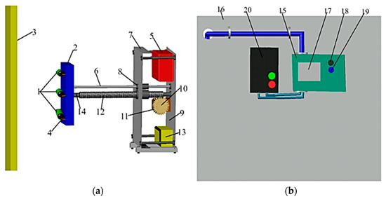
Figure 13.
Resource saving Electric Motor Current Protection with Remote Setpoint Selection: (a) placed in the switchgear panel; (b) gear motor control unit.
The gear motor (10) is powered by the control unit (15) installed in the protective cabinet (16). On the front panel of the control unit (15), there is a display (17) for controlling the operation, as well as the “forward–backward” control buttons (18; 19) for the gear motor (10). The control unit (15) is powered by the circuit breaker (20) (Figure 13b).
Regulation of triggering parameters of current protections from short-circuit currents is carried out by approaching the current-carrying busbar (3), plate (2) and reed switches (1). At the same time, one protection uses one of the three reed switches (1). The plate (2) is moved by means of a geared motor (10) by pressing buttons (18; 19). The required distance from the plate (2) to the current-carrying bus (3) in a cubicle switchgear is defined by turning the geared motor (10) implemented by a microcontroller mounted on the control unit (15).
Before installing, the device in the switchgear cubicle calculates the necessary distance from the current-carrying bus (3) to the reed switches (1) and the angle at which the reed switch (1) must be in relation to the lines of force of the magnetic field created by the current in the current-carrying bus (3); according to the table, we take the reed switch (1) with a given magnetomotive force of operation.
The current protection works as follows. In the bus compartment of the cell at a safe distance equal to 0.12 m (the minimum allowable distance according to Electrical Installation Regulations from live parts of electrical installations with voltage U = 10 kV) from the live busbars (3), we install three penalized enclosures (7). In the bay protection cabinet (16), we place and connect the control unit (15) and circuit breaker (20). Then, we turn on the circuit breaker (20) supplying power to all elements of the current protection device (Figure 13b).
As an example, consider the setting of protection for phase A made with one of the three reed switches (1) (the first) located on the plate (2) relative to the plane of the cross-section of the current-carrying busbar (3) at an angle of 00. The remaining two reed switches (1), also located on the plate (2), are designed to provide a more accurate choice of settings, and will be used in case the reed switch (1) (the first) cannot be selected with the necessary magnetomotive force. At the very beginning, the display (17) of the control unit (15) shows the distance to the current-carrying busbars (3) at which the plate (2) with the reed switches (1) is currently located, e.g., 0.15 m. Then, by pressing the “Forward” button (18), the geared motor (10) is started which moves the plate (2) together with the reed switches (1) closer to the current-carrying busbars (3). After the display (17) shows the value 0.12 m, the release button (18) and thus the reed switch (1) are smoothly set at the necessary distance from the current-carrying busbar (3) of phase A. Similarly, the current protection (the other two hangers (7)) is set for the other two phases B and C.
When a short circuit in the protected electric motor, the current flowing on the current-carrying bus (3) of the switchgear panel exceeds the current operation of protection, at which point, one of the reed switches (1) triggers (closes contacts), sending a signal to the time setter (6), which, after a specified time delay, sends a signal to the executive (13), which in turn sends a signal to the circuit breaker of the electric motor.
In nominal load modes, the electric motor current does not exceed its maximum value, and in this regard, the reed switches (1) are not triggered. The motor reducer (10) makes it possible to remotely adjust the distance from the reed switches (1) to the current-carrying busbar (3) of the switchgear panel, thus ensuring the selection of the required setting of the electric motor current protection operation and the absence of the use of expensive and bulky current transformer ferromagnetic cores (compared with reed switches), providing significant savings in material resources, which together makes it possible to use this current protection in any series of switchgear cells to implement current protections of electric motors of any type and voltage class.
6. Conclusions
All the numerical parameters and dependencies derived from the experiments are presented in the figures. The EMF is higher when the plate (18) is at the second and, especially, the third positions than when it is in the first position. This is explained by the fact that ICs (15) in this position are as close as possible to the metal structures of cell 1, which produce additional magnetic fields (interference).
The analysis of the experiments we performed has shown that when the first plate (18) is at the first position, the EMF is maximal at the following points:
- -
- At 22, 47 and 68 cm at a distance of 12 cm from the current carrying busbars;
- -
- At 22, 47 and 74 cm at a distance of 18 cm;
- -
- At 16, 47 and 74 cm at a distance of 24 cm from busbars (12).
When the first plate (18) is at the second and third positions, the EMF is maximal at the following points:
- -
- At 1, 23, 45 and 68 cm at a distance of 12 cm;
- -
- At 1, 24, 45 and 70 cm at a distance of 18 cm;
- -
- At 1, 24, 47 and 64 cm at a distance of 24 cm from the busbars (12), respectively.
Taking into account the field experiments for all short circuit types, which enable identifying points where the EMF is maximal, we have ascertained that actuators of the suggested protection, which are reed switches, are advisable to mount at the first position of the first plate (18), opposite the center of the axes (because the magnetic induction maximum is concentrated there) of the current-carrying busbars (12) of cell 1 at a distance of 12 cm from them, where the EMF is higher than at the other two distances of 18 and 24 cm. Considering the difficulty associated with the detuning of the overcurrent protection, it is also not desirable to mount the reed switches at the second and third positions of the first plate (18) because of the strong effect of the metal structures of cell 1, which produced additional interference.
Finally, we recommend the following. The suggested resource-saving protection can be used as an overcurrent protection for electrical installations connected to 6–10-kV switchgear cells. Our experiments with cells 1 and 2 have shown a possibility of creating resource-saving overcurrent protection using magnetic field sensors based on reed switches. This protection meets the requirements for relay protections and can be an alternative to traditional current protection. All the above is confirmed by the selection of settings for resource-saving overcurrent protection and verification of its sensitivity coefficient. The suggested overcurrent protection can be used for different electrical installations with any class of rated voltage, for example, 35, 110, 220 kV and so on.
The application of the developed protections will ensure the following:
- -
- The refusal of the use of measuring current transformers is in accordance with the strategically important task set by the international committee on large power systems of CIGRE. The resource-saving effect consists of a reduction in expenses for the realization of current protection, which in the end leads to an increase in material income of the world power industry and the world community as a whole by an amount greater than the initial expenses for the arrangement of this protection;
- -
- The expected results of the development of the main scientific direction (relay protection and automation) and related fields of science and technology have an impact on the development of resource-saving relay protection without the use of traditional current transformers.
The scientific and technical effect is that the developed protections are not inferior to the existing traditional protections made with the use of measuring current transformers.
The economic effects are as follows:
- -
- Developed protections perform the functions of an analog-discrete and measuring converter and the same protection body, and are resource-saving, consisting of minimizing initial material costs and subsequently minimum annual costs during operation;
- -
- Development of competitive, resource-saving relay protection for the future, and a reduction in production costs of such protection, namely that produced at stations, and electricity consumed at substations of enterprises, as well as a growth in labor productivity due to a reduction in time when producing such protection devices in comparison with the time spent on traditional production.
The environmental effect consists of saving both the extraction of non-ferrous and ferrous metals from the earth’s surface and their further processing at metallurgical plants. As a result, the load on power generation by power plants and on non-ferrous and ferrous metal consumption in the production of traditional measurements of current transformers is simultaneously reduced. The tasks of environmental protection and reduction in harmful emissions of production are solved; there is a reduced or even complete absence of heat and power consumption during the production of traditional current transformers due to their uselessness for power supply of relay protection devices. At the same time, the emission of harmful substances into the atmosphere of the planet decreases, and as a result, various human pathologies and diseases related to ecology are reduced. At the same time, the healthy and able-bodied population increases, which is undoubtedly a powerful personnel and social effect.
The conducted experiments, their results, and selected protection settings confirm the efficiency of the suggested resource-saving overcurrent protection as an alternative to traditional current protections. The results of this work significantly contribute to the further scientific development of power engineering and, in particular, relay protection (automation). The high efficiency of the presented overcurrent protection is also confirmed by the graphically represented experimental results with their detailed analysis, which clearly show the maximum and minimum points of EMF values, the selection of settings for resource-saving current protection, and technical and economical assessments.
7. Patents
- (1)
- Dauren Jambulovich Issabekov, KZ Patent “Design for preventing an overhead crane from crossing the maximum permissible positions on reed switches”, № 35293, Bulletin № 38, 24.09.2021, https://gosreestr.kazpatent.kz/Invention/Details?docNumber=330114, accessed on 27 September 2021;
- (2)
- Dauren Jambulovich Issabekov, KZ Patent “Device for maximum current protection of electrical installations on magnetically controlled elements”, № 35387, Bulletin № 47, 26.11.2021, https://gosreestr.kazpatent.kz/Invention/Details?docNumber=330086, accessed on 27 October 2021
Positive Aspects of the Research
The conducted experiments aimed at further development of current protections for different electrical installations connected to switchgear cells suggest a way of saving significant amounts of copper, steel and high-voltage insulation due to the complete refusal of the use of traditional measuring current transformers with metal cores. In the future, field experiments on the development of alternative resource-saving current protections for different 6-10 kV electrical installations will be continued, including for other voltage classes and other relay protection types, such as differential and gas protections for electrical installations both connected to switchgear cells and closed switchgears and for separate electrical installations, for example, gas protections for oil-filled arc-fault-reactive reactors. The results of experimental research can be used by the scientific community, industrial enterprises, power stations and substations of plants.
Author Contributions
Conceptualization: D.D.I.; Research: D.D.I. and D.S.N.; Writing—preparation of the initial draft: D.D.I. and A.P.K.; Writing—reviewing and editing: A.P.K., N.S.Z. and V.P.M.; Supervision: D.S.N., A.K.Z. and V.P.M.; Project Administration: V.P.M., N.S.Z. and A.K.Z.; Obtaining funding: D.D.I. All authors have read and agreed to the published version of the manuscript.
Funding
This research was funded by the Committee on Science of the Ministry of Science and Higher Education of the Republic of Kazakhstan (grant no. AP14972954).
Data Availability Statement
The original contributions presented in the study are included in the article, further inquiries can be directed to the corresponding author.
Conflicts of Interest
All authors of the submitted work declare that they have no known personal relationships or competing financial interests that could influence the work presented in this article.
Nomenclature
| E | electromotive force (EMF) |
| field damping coefficient | |
| magnetic induction | |
| electric current | |
| magnetic field strength | |
| correction factor | |
| phase coefficient | |
| maximal operating current of the protected electrical installation | |
| detuning coefficient | |
| electric motor self-starting | |
| return coefficient | |
| protection operation current | |
| = 4π·10−7 Gn/m | |
| protection operation induction | |
| h | distance from the axis of a current-carrying busbar to the center of gravity of a reed switch |
| induction of magnetic fields from currents phases of cell 1 where a reed switch is mounted | |
| induction of magnetic fields from the currents in two neighboring switchgear cells located to the left and right of cell 1 | |
| sensitivity coefficient | |
| minimal short-circuit current | |
| magnetic field induction produced by minimal short-circuit current | |
| actuation induction of a reed switch mounted in cell 1 | |
| magnetomotive force (MMF) of reed switch actuation | |
| total nominal power of a transformer | |
| nominal voltage of the electrical installation |
Appendix A
Selection of settings for the resource-saving overcurrent protection
The method for calculating the settings for the suggested reed switch overcurrent protection consists of Formulas (A1)–(A10). To prove the correctness of the choice of the settings of the protection, let us compare this method with the choice of settings of traditional overcurrent protections. When adjusting a traditional overcurrent protection, its operation current should be higher than the maximal operating current of a protected electrical installation connected to cell 1. Taking into account the detuning coefficient , which takes into account the errors of instruments and protection devices and inaccuracies of calculations, the electric motor self-starting coefficient and return coefficient , the operation current is defined as [4]:
However, taking into account that the action of reed switch protection depends on the magnetic field strength of a conductor with current, we recalculate the operation current in the corresponding induction at the reed switch fixing point according to the Biot–Savart law. To ensure the sensitivity of the protection, we consider that a reed switch is mounted in the cross-sectional plane of a current-carrying bus perpendicular to the straight line passing through the center of gravity of the reed switch and the axis of this bus, and the induction of operation the reed switch protection is defined as [37]:
where = 4π × 10−7 Gn/m is the magnetic constant; h is the distance from the axis of the current-carrying busbar to the center of gravity of the reed switch; is the maximal operating current of the electrical installation connected to cell 1.
Taking into account that the Biot–Savart law is applicable to an infinitely long and thin conductor and does not take into account the interference and errors due to inaccuracy of reed switch mounting at a given point, alternating current, field distortion and current-carrying busbar shape, the settings for the reed switch overcurrent protection are selected from the condition:
where , , are the inductions of magnetic fields from currents in phases of cell 1 where the reed switches are mounted and two neighboring switchgear cells are located to the left and right of cell 1.
When constructing an overcurrent protection for electrical installations connected to the switchgear cells, the induction is produced by the current in the phase near which the reed switch is mounted. Two other inductions inside cell 1 act on the reed switch when the maximal operating load current flows through the other two phases, which is taken into account by the phase coefficient . Since the currents in the phases of the electrical installation connected to the cell are equal in magnitude, we take them equal to . Induction is induced during three or two-phase short-circuits in electrical installations connected to the switchgear neighboring cells located to the left and right of the tested cell.
It should be noted that the current on the body of cell 1 (but not in current-carrying busbars), where the reed switches are mounted, is not taken into account, because this current flows in two cases: (a) during single-phase earth faults; (b) during double faults, when one of the faults occurs in the considered switchgear cell. In the first case, the short-circuit currents are small and the induction of the magnetic fields produced by them can be neglected. In the second case, if the currents in the cell increase the induction acting on a reed switch, this increases the protection sensitivity, and if the current decreases the induction, this should be taken into account when determining the sensitivity.
The values of the above summands also depend on the accuracy of mounting a reed switch. In this case, the induction of the magnetic field of the first cell from the current-carrying bus, where the reed switch is mounted, decreases, while the induction of the magnetic field of the neighboring (second) cell can increase. The error of reed switch mounting at a given point should be no more than 3% [38], and the effect of this error on of the phase opposite to which the reed switch is mounted can be neglected, which gives a reserve on the induction of the protection operation . The effect of this error on on of the other two phases and can be taken into account by introducing an additional adjustment factor = 1.1.
Assuming that the self-starting of electric motors occurs only after short-circuit clearing, the selection of the settings of the reed switch overcurrent protection is performed as follows:
(1) When there are two neighboring switchgear cells:
where is the maximal operating current of neighboring switchgear cells;
(2) In case of a short circuit in electrical installations connected to neighboring cells:
where is the current of a three-phase short circuit on neighboring electrical installations; is the correction factor taking into account errors due to the alternating current in current-carrying busbars and magnetic field distortion.
If the protection is performed with voltage blocking, then the effect of disturbances from currents in electrical installations connected to neighboring cells can be ignored, and the induction can be calculated by Equation (A2) neglecting the inductions of neighboring cells and .
If the protection is performed with voltage blocking, then the effect of disturbances from currents in electrical installations connected to neighboring cells can be ignored, and the induction can be calculated by Equation (A2) neglecting the inductions of neighboring cells and .
Appendix A.1. Verification of Sensitivity Coefficient of the Reed Switch Overcurrent Protection
The sensitivity coefficient of a traditional current protection is determined by the formula [4]:
where is the minimal short-circuit current.
But a reed switch is known to be triggered by the magnetic induction; therefore,
where is the induction of the magnetic field produced by the minimal short-circuit current flowing in the current-carrying busbars at the point where a reed switch is mounted accounting the correction factor .
Instead of the theoretically chosen protection operation induction , we use here the reed switch actuation induction . Calculating and using the experimentally obtained coefficients, we select a reed switch with the actuation induction according to the formula
However, this ratio is not always feasible. If , then it is necessary to check whether the protection has the required sensitivity. If yes, i.e., if ≥ 1.5 at the end of the protected section and ≥ 1.2 at the end of the adjacent section [4], then we accept = . If the current protection does not meet the sensitivity requirements, a reed switch is mounted closer to the current-carrying busbar. Since the reed switch point has changed, the distance h to the reed switch also changes (decreases); the protection operation induction is recalculated with the new h value. Then, the new value of is compared with , and the sensitivity coefficient . If ≥ , then
If the requirements for the protection sensitivity are met, the protection is mounted, else the reed switch is moved closer to the busbar and the above steps are repeated. If ≤ , then it is necessary to move the reed switch away from the busbar. In this case, the distance h to the current-carrying busbar (12) is increased and the protection operation induction is recalculated. Next, the induction of the reed switch operation and the induction of the protection operation are compared in a similar way. If ≥ , then the protection is checked in terms of the sensitivity coefficient. If this condition is met, the current protection is mounted. If not, the reed switch is moved further away from the busbar. If there is a neighboring cell next to the protected switchgear cell, then for protection without voltage blocking, it is necessary to take into account the current interference in the latter, and its value is calculated according to the above method.
Appendix A.2. Example of Selecting Settings for the Resource-Saving Reed Switch Overcurrent Protection
Let us calculate the overcurrent protection when two neighboring switchgear cells are located on both sides (to the left and to the right) of cell 1 in case of a three-phase short-circuit in the electrical installation connected to cell 1.
Let us calculate for the overcurrent protection with voltage blocking, for a cable line supplying a TM-2500/10 transformer with winding connection Y/Y-0 with a voltage of 0.4 kV on its lower side. When selecting the operation current of the protection, we assume = 5 and = 1.1 [4]. Then,
where is the full rated power of the transformer; is the nominal voltage of the installation.
Let us mount a reed switch at a distance of 12 cm from the center of the busbar axis. Taking into account the maximal operating current on this installation = 145 A, the maximal operating currents of the installation connected to cell 2, which is located to the right of cell 1, = 300 A, and the maximal operating current of the installation connected to cell 3, which is located to the left of cell 1, = 400 A, as well as the coefficients = 1.1; the phase coefficient in the case where the I = 600 A flows through one (A) and three (ABC) busbars = 3.75, = 5, = 2.36, = 1.58 and = 2.5, we obtain
In this case, the induction of the reed switch protection operation is determined without taking interference into account, because the protection is performed with voltage blocking.
Let us take for example a MKA-50202 reed switch (Ryazan Plant of Metal Ceramic Products) [34] with the actuation EMF = 100 A × windings. From the reference data for this reed switch type, we take the length of its coil = 0.0428 m. Then, induction of reed switch actuation
According to the calculations, the induction of reed switch actuation is higher than the induction of protection operation: ˃ . Therefore, we check the protection sensitivity of the by determining its sensitivity coefficient .
For a cable line with Unom = 10 kV and a distance of 1 km between cell 1 and a transformer substation, maximal operating current = 145 A. According to reference data [39] we take a cable of mark ASB 3 × 70 with Inom = 185 A and active and inductive Rcab = 0.443 ohm/km and Xcab = 0.086 ohm/km. The minimal short-circuit current is ISC = 11.7 kA [40]. Then, the induction of the magnetic field created by the minimal short-circuit current flowing through the current-carrying busbar opposite to which the reed switch is mounted
Substituting the values of and in Equation (A9), we find
Hence, the sensitivity coefficient of the current protection is higher than its minimal value required by the relay protection, that is, = 2.2 ˃ 1.5.
This answer confirms the correctness of the conclusions that the suggested resource-saving reed switch overcurrent protection can be used as an alternative to the traditional current protections made by measuring current transformers with metal cores.
Appendix B
Technical and economical substantiation of the efficiency of the resource-saving overcurrent protection.
Let us consider the current protection of electrical installations on reed switches with remote control of operative current [41] as the suggested protection.
The device includes three units for fixing reed switches. Each block includes a plate (1) with six reed switches (2–7) fixed on its outer side at different angles to the cross-sectional plane of the current-carrying busbar (8). A plate (1) is attached to the central holder (9) and side holder (10). The holder (9) is attached to the toothed belt (11), which is movable along it relative to the busbar (8). The holders (10) are attached to running axles (12). The ends of the axles (12) are attached to the first (13) and second (14) supports mounted on the lower base of the bus compartment of the switchgear cell using the clip angle (15), screws (16), and bolted connection (17). A step motor (18) and winding mechanism (19) are attached to the support (13). A toothed pulley (20) and coupling (21) are attached to an electric motor (18). The toothed pulley (22) is attached to the support (14) using a mounting plate (23). The toothed belt (11) is put on pulleys (20 and 22) (Figure A1a). One of the contact cores of the reed switches (2–7) is connected to a timing unit (24) by a cable (25), one end of which is fixed to the plate (1), laid through the air to the mechanism (19), then along the support (13) and the lower base of the bus compartment, and inserted into the plastic sleeve (26) laid along the lower base and rear wall of the bus compartment to the timing unit (24); the other end of the cable (25) is connected to the components in Figure A1b. Another contact core of the reed switches (2–7) is connected by a cable (25) to the positive output of the circuit breaker (27). The step motor (18) is connected to the panel (29) with a touch display (30) by a cable (28). The cable (28) is laid along the support (13), passes along the lower base of the bus compartment, and is inserted into a plastic sleeve (26). The cables (25 and 28) and plastic sleeve (26) are attached to the support (13), the lower base and the wall of the bus compartment by plastic clamps (31). The first and second inputs of the control panel (29) are connected to the positive and negative outputs of the switch (27) by wires (32) (Figure A1c). One input of the actuator (33) is connected to the output of the timing unit (24) by wires (34), and the other input is connected to the negative output of the circuit breaker (27). To seal the inputs and outputs of the plate (1), timing unit (24), control panel (29), and actuator (33), rubber gaskets (35–41) are used.
Reed switches of KEM-1 type can be used as the reed switches (2–7); Olflex classic 100 cables of 4 × 1.5 in size and Olflex classic 100 of 8 × 1.5 in size are used as the cables (25 and 28); the wires (32 and 34) are PV-1 × 6 brand; the step motor (18) is of SL42STH48-1504A type; the automatic switch (27) is of AP-50 type. All elements, except for the step motor, clip angle, screws and bolted connections, are made of non-magnetic material.
The device works as follows. Let one of six reed switches with different EMFs located in the cross-sectional plane of the busbar (8) be used as the protection, for example, of a 5-MW VAO-5000-2 UHL4 electric motor connected to a K-63 switchgear cell. The settings are calculated and a reed switch is selected; let it be the reed switch (2), which is located at a zero angle to the cross-sectional plane of the busbar (8). Then, three reed units for mounting reed switches are installed in the bus compartment at a safe distance (at least 0.12 m) from the current-carrying busbar (8), and cables (25 and 28) are laid into the sleeve (26). The block (24), switch (27), panel (29), and actuator (33) are placed in the protection cabinet and connected. Next, the switch (27) is turned on and power is supplied to all elements of the protection. The touch display (30) of the panel (29) displays the distance between the plate (1) and the busbars (8), for example, 0.2 m, while 0.18 m is required according to the calculations.
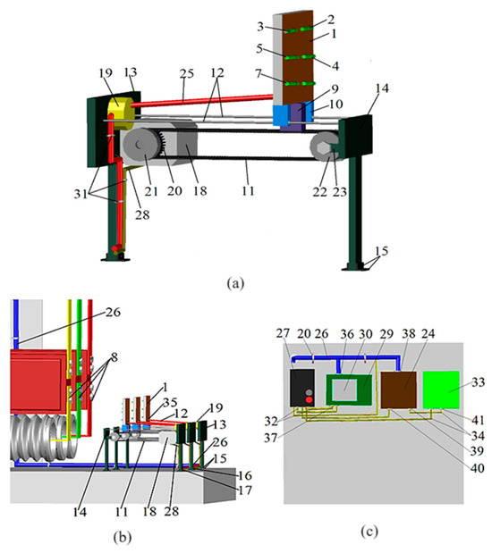
Figure A1.
Reed switch overcurrent protection of electrical installations with remote control of operative current: (a) unit for mounting reed switches; (b) arrangement of these units in the bus compartment; (c) control panel, timing unit, and actuator in the cell protection cabinet.
Then, “pressing” the virtual button “Forward” (not shown in the figure) on display 30, electric motor 18 is started, which moves the plate (1) closer to the busbars (8). When moving the plate (1), the length of the first connecting cable (25) is fixed using the winding mechanism (19) in order to avoid sagging. After the value 0.18 m is displayed on the display (30), the “Forward” button is released. The reed switch (2) is mounted at the required distance from the busbars (8). The remaining reed switch mounting units are adjusted in the same way. When a short circuit occurs at the terminals of the protected electric motor, the current in the busbars (8) becomes higher than the protection operation current, and the reed switch (2) closes its contacts and sends a signal to the input of the block (24), which sends a signal to the input of the actuator (33) after a time delay.
Thus, this device enables remote and smooth movement of reed switches relative to the plane of the current-carrying busbars, thus controlling the protection response settings without shutting down the electrical installation.
Let us calculate the technical and economic efficiency of the resource-saving current protection and electromechanical, semiconductor, and microprocessor-based current protections. The national currency of the Republic of Kazakhstan is the tenge. Therefore, all calculations are presented in tenge. The cost of the suggested current protection of electrical installations on reed switches with remote control of operative current consists of the costs of components, including KEM-1 reed switch [34] (420 tenge), stepper motor (2130 tenge), toothed belt (250 tenge), components for the reed switch mounting unit: plate (100 g of PLA plastic) (400 tenge), supports, running axles, central and side holders (400 g of PLA plastic) (1600 tenge); Olflex classic cables: (1) 8 × 1.5 mm2 cross section with a connector connecting the reed switches to the timing unit (180 tenge × 5 m = 900 tenge); (2) 4 × 1.5 mm2 cross section connecting the step motor to the control panel (120 tenge × 5 m = 600 tenge); reed switch current relay with test diagnostics of faults (9000 tenge); control panel (10,000 tenge); touch display (2600 tenge).
Reed switches are fixed on a plate placed on the mounting block. The cost of one such block is 15,300 tenge. Let us add to this sum the cost of a control panel with a touch display divided by three (since three units for mounting reed switches are attached to it): 15300 + 18600/3 = 21500 tenge. Manufacturing and adjustment of the device cost 2000 tenge. The total cost is 23,500 tenge. The cost of the device also includes travel expenses for trips to substations of industrial enterprises (within the region and the republic), and then the cost of the device is about 30–35 thousand tenge.
Since semiconductor and electromechanical relay protection devices still successfully operate at substations of industrial enterprises in addition to widespread microprocessor-based relay protection devices (manufactured in countries across the former Soviet Union and beyond), we take this into account in technical and economical comparison. For example, the average cost of a TPO-10 current transformer with a metal core with the transformation ratio = 300/5 is 60,000 tenge (Russia), and together with it the cost is composed of a Schneider Electric MiCOM microprocessor terminal (358,000 tenge); a semiconductor current relay (Russia) (95,000 tenge), and an RT-40/10 electromechanical relay (Russia) (68,000 tenge).
The technical and economic efficiency of the two protection versions can be compared in terms of costs calculated by the equation [42]:
where is the reduced costs of the i-th version per operating year; is the annual cost of operation of the i-th version per operating year; is the annual average damage due to the unreliability of the power supply for the i-th version; is the norm coefficient ( = 0.125 at the payback time = 8 years).
The reduced cost for the i-th protection device is calculated by the formula [43]:
where is the annual cost of operation of the i-th protection; is the annual mean damage with neglect of its unreliability with multiple recognition of protection modes; is the price of the i-th relay protection device ( is the price of the suggested i-th device).
If the protection fails to operate, damage occurs. This takes into account the following costs: to replace broken equipment; for post-accident repairs or damage due to a sudden failure; and a shortfall in production due to the failure of electrical installations connected to switchgear cells.
We consider the annual average damage during operation of the suggested device and traditional protection systems to be approximately equal to Dfn = DPR; they depend on the reliability of operation (failure to operate). The frequency of failure of the suggested device can be correctly estimated in comparison with traditional ones only with sufficient operating experience. Costs C and the norm coefficients are considered equal, since there is no reason to consider them unequal, i.e.,: PN = PPR. Taking into account the above, the economic effect of the suggested protection device (with the difference in costs CPR = CR, where CR are the reduced costs of operation of the suggested device) is
where is the number of new devices suggested for implementation.
Taking into account the fact that the Cn = 357,000 tenge for a microprocessor device and Cnm = 30,000 tenge for the suggested device, for PN = 0.125 and n = 1, E = (358,000 − 30,000) × 0.125 1 = 41,000 tenge per year. For a 6–10-kV switchgear with the number of connections n = 22, the possible economic effect E = 902,000 tenge.
The comparison of the suggested device [43] with traditional ones shows that the first is superior to them since it is 15 times cheaper than, for example, MiCOM microprocessor device (economic effect E1 = 41,000 tenge per year at n = 1); semiconductor and electromechanical devices are cheaper by 4 and 2.9 times and the economic effect E2 = 8125 and E3 = 4750 tenge per year, respectively.
References
- Andreev, J.V. Relay Protection and Automatics of Power Supply Systems, 4th ed.; Higher School: Moscow, Russia, 2008; 608p. [Google Scholar]
- Fedoseev, A.M.; Fedoseev, M.A. Relay Protection of Electric Power Systems: Textbook for Universities, 2nd ed.; Revision and Addendum. M.; Energoatomizdat: Moscow, Russia, 1992. [Google Scholar]
- Shneerson, E.M. Digital Relay Protection; Energoatomizdat: Moscow, Russia, 2007. [Google Scholar]
- Chernobrovov, N.V.; Semyonov, V.A. Relay Protection of Power Systems; Energoatomizdat: Moscow, Russia, 1998; 800p. [Google Scholar]
- Dyakov, A. Electric-Power Industry in the World in Early 21st Century (According to the Materials of the 39th CIGRE Session, Paris), Energetika Zarubezhom 4–5; Scientific and Technical Firm “Energoprogress”: Moscow, Russia, 2004; pp. 44–45. [Google Scholar]
- Kletsel, M.Y. Fundamentals of relay protection based on reed switches. In Modern Directions of Development of Relay Protection and Automation of Power Systems; Collection of Conference Reports; SIGRE: Ekaterinburg, Russia, 2013. [Google Scholar]
- Maisels, R.M.; Shoffa, V.N. Reed switches. In A Look at the Prospects of the Direction; Electrical Engineering; Energia Publishing House: Moscow, Russia, 1998; pp. 20–25. [Google Scholar]
- Sverdlovsk Plant of Current Transformers. Available online: https://www.cztt.ru/catalog/transformatory-toka/transformatory-toka-naruzhnoy-ustanovki/opornye1/10-kv-1/tol10iii/ (accessed on 7 December 2023).
- Borodenko, V.A.; Barukin, A.S.; Kaltaev, A.G. Investigation of the Alternating Current Sensor on a Reed Switch with a Coil; PSU Vestnik; Energy Series; Vestnik: Krasnodar Krai, Russia, 2016; pp. 23–28. [Google Scholar]
- Elmitwally, A.; Gouda, E.; Eladawy, S. Optimal allocation of fault current limiters for sustaining overcurrent relays coordination in a power system with distributed generation. Alex. Eng. J. 2015, 54, 1077–1089. [Google Scholar] [CrossRef]
- Baranochnikov, M.L. Micromagnetoelectronics, (Textbook Series), Electronic version; DMK Press: Moscow, Russia, 2001; Volume 1, 373p, Available online: https://www.elec.ru/viewer?url=files/2020/01/31/Tom_1_N.pdf (accessed on 10 April 2024).
- Issabekov, D.D. Resource-saving protections of power transformers against internal faults. In Proceedings of the 4th International Conference on Energetics, Civil and Agricultural Engineering (ICECAE 2023), E3S Web of Conferences 434, 01041, ICECAE, Tashkent, Uzbekistan, 12–14 October 2023; pp. 35–39. [Google Scholar] [CrossRef]
- Paladhi, S.; Pradhan, A.K. Resilient protection scheme preserving system integrity during stressed condition. IET Gener. Trans. Distrib. 2019, 13, 3188–3194. [Google Scholar] [CrossRef]
- de Andrade Ferreira, R.S.; de Araujo, J.F.; Andrade, F.L.M.; Costa, E.G.; Guerra, F.C.F. Influence of electromagnetic forces in the gaps of a protective CT. IET Sci. Meas. Technol. 2018, 12, 872–877. [Google Scholar] [CrossRef]
- Zhu, K.; Han, W.; Lee, W.K.; Pong, P.W.T. On-Site Non-Invasive Current Monitoring of Multi-Core Underground Power Cables with a Magnetic-Field Sensing Platform at a Substation. IEEE Sens. J. 2017, 17, 1837–1848. [Google Scholar] [CrossRef]
- Chen, Y.; Huang, Q.; Khawaja, A.H. Interference-rejecting current measurement method with tunnel magnetoresistive magnetic sensor array. IET Sci. Meas. Technol. 2018, 12, 733–738. [Google Scholar] [CrossRef]
- Zhou, M.; Centeno, V.; Thorp, J.S.; Phadke, A.G. Calibrating Instrument Transformers with Phasor Measurements. Electr. Power Compon. Syst. 2012, 40, 1605–1620. [Google Scholar] [CrossRef]
- Nascimento, I.M.; Brígida, A.C.S.; Baptista, J.M.; Costa, J.C.W.A.; Martinez, M.A.G.; Jorge, P.A.S. Novel optical current sensor for metering and protection in high power applications. Electr. Power Compon. Syst. 2016, 44, 150904032551004. [Google Scholar] [CrossRef]
- Gurevich, V. Electrical relay. In Device, Principle of Operation and Application; SOLON-PRESS: Helsinki, Finland, 2011; 688p. [Google Scholar]
- Egiazaryan, G.A.; Stafeev, V.I. Magnetodiodes, Magnetotransistors and Their Applications; Radio and Communication: Moscow, Russia, 1987. [Google Scholar]
- Kotenko, G.I. Magnetoresistors. L; Energy: Moscow, Russia, 1972. [Google Scholar]
- Crescentini, M.; Syeda, S.F.; Gibiino, G.P. Hall-effect current sensors: Principles of operation and implementation techniques. IEEE Sens. J. 2022, 22, 1. [Google Scholar] [CrossRef]
- Solovev, D.B.; Kuzora, S.S. Implementation of Noise-Immune Rogowski Coils for Busbar Differential Protection Modernization. Electr. Power Syst. Res. 2016, 140, 965–966. [Google Scholar] [CrossRef]
- Kozhovich, L.A. Non-Conventional Instrument Transformers for Improved Substation Design; CIGRE Session: Paris, France, 2016. [Google Scholar]
- Karabanov, S.M.; Maisels, R.M.; Shoffa, V.N. New Designs and Perspectives of Reed Switches Development in Russia; Electrical Contacts and Electrodes; dSAPACE: Paderborn, Germany, 2010; pp. 9–17. [Google Scholar]
- Dikovskiy, Y.M.; Kapralov, I.I. Magnetic Contacts; Energy: Moscow, Russia, 1970; 152p. [Google Scholar]
- Karabanov, S.M.; Maisels, R.M.; Shoffa, V.N. Magnetically Operated Contacts (Reed Switches) and Products Based on Them; Publishing House Intellect: Dolgoprudny, Russia, 2011. [Google Scholar]
- Gurevich, V. Electric Relays: Principles and Applications; CRC Press Taylor & Francis Group: Abingdon, UK, 2006; p. 671. [Google Scholar]
- Barukin, A.S. Construction for Fixing the Reed Switches of the Protections of High-Voltage Electrical Installations Near the Busbars of Closed Conductors of DC Current. In Proceedings of the International Scientific and Practical Conference “IX Toraigyrov Readings”, Pavlodar, Kazakhstan, 17 November 2017; pp. 13–17. Available online: https://tou.edu.kz/arm/storage/science/doc/%D0%A2%D0%BE%D1%80%D0%B0%D0%B9%D0%B3%D1%8B%D1%80%D0%BE%D0%B2%D1%81%D0%BA%D0%B8%D0%B5%20%D1%87%D1%82%D0%B5%D0%BD%D0%B8%D1%8F%20%D0%86%D0%A5,%207%20%D1%82%D0%BE%D0%BC,%202017.pdf.pdf (accessed on 26 April 2024).
- Karabanov, S.M.; Maisels, R.M. Reed relays. In A Look at the Prospects of the Direction Development; Components and Technologies; Cyberleninka: Moscow, Russia, 2001; pp. 28–30. [Google Scholar]
- Issabekov, D.D. Multipurpose Power System Protection Set that Provides Constant Remote Serviceability Control. In Proceedings of the Collection of Papers of 2022 International Conference on Industrial Engineering, Sochi, Russia, 16–20 May 2022; pp. 35–39. [Google Scholar] [CrossRef]
- Relay MKU 48. JSC “Irkutsk Relay Plant”. Available online: https://irzirk.ru/catalog/element/rele_mku_48s_ra4500136_ra0450002_tu/ (accessed on 14 September 2023).
- Order of the Minister of Energy of the Republic of Kazakhstan. In Rules for the Device of Electrical Installations of the Republic of Kazakhstan; The Ministry of Energy of the Republic of Kazakhstan: Astana, Kazakhstan, 2015.
- Joint Stock Company. Ryazan Plant of Metalloceramic Devices. Available online: http://www.rmcip.ru/files/catalogue/mka_502021.pdf (accessed on 9 August 2023).
- Doroshev, K.I. Complete Switchgears 6–35 kV; Energoizdat: Moscow, Russia, 1982; 376p. [Google Scholar]
- Complete Distribution Device with Voltage 6–10 kV. KRU K-63; Technical Information; Open Public Association Siberian Plant “Electroshield”: Novosibirsk, Russia, 2015.
- Bessonov, L.A. Theoretical bases of electrical engineering. In Electromagnetic Field; Gardariki: Moscow, Russia, 2001; 317p. [Google Scholar]
- Kletsel, M.Y.; Neftisov, A.V.; Maishev, P.N.; Zhantlesova, A.B. Identification of the Steady-State Short-Circuit Current Using Reed Switches; Elektrotekhnika: Prague, Czech Republic, 2014; pp. 28–34. [Google Scholar]
- Neklepaev, B.N.; Kryuchkov, I.P. Electrical Part of Power Stations and Substations: Reference Materials for Course and Diploma Design: A Textbook for Universities-4 izdu, Rev.; Energoatomizdat: Moscow, Russia, 1989; 608p. [Google Scholar]
- Shabad, M.A. Calculations of Relay Protection and Distribution Automation Networks, 3rd ed.; Energoarotizdat. Lenin r. Department: Leningrad, Russia, 1985; 296p. [Google Scholar]
- Isabekov, D.D. Current Protection of Electrical Installations on Reed Switches with Remote Control of Operative Current. KZ Patent No. 33525, 26 December 2019. [Google Scholar]
- Rogalyov, N.D.; Zubkova, A.D.; Masterova, I.V.; Kurdyukova, G.N.; Bologova, V.V.; Ponamaryova, O.Y. Economics of Power Engineering: Textbook for Universities; MPEI Publishing House: Moscow, Russia, 2005; Available online: https://e.lanbook.com/book/72321 (accessed on 5 January 2023).
- Kuzhekov, S.L.; Okley, P.I.; Nudelman, G.S. Analysis of a Set of Requirements to Relay Protection in Order to Assess Its Efficiency; Electric Power Stations 2; Electric Power Stations Publishing House: Moscow, Russia, 2010; pp. 43–48. [Google Scholar]
Disclaimer/Publisher’s Note: The statements, opinions and data contained in all publications are solely those of the individual author(s) and contributor(s) and not of MDPI and/or the editor(s). MDPI and/or the editor(s) disclaim responsibility for any injury to people or property resulting from any ideas, methods, instructions or products referred to in the content. |
© 2024 by the authors. Licensee MDPI, Basel, Switzerland. This article is an open access article distributed under the terms and conditions of the Creative Commons Attribution (CC BY) license (https://creativecommons.org/licenses/by/4.0/).