Review

E-Fuels: A Comprehensive Review of the Most Promising Technological Alternatives towards an Energy Transition

by
Sonia Dell’Aversano
1,*,†,
Carlo Villante
1,†,
Katia Gallucci
1,†,
Giuseppina Vanga
2,† and
Andrea Di Giuliano
1,†
1
Department of Industrial and Information Engineering and Economics, University of L’Aquila, Monteluco di Roio, 67100 L’Aquila, Italy
2
ENEA—Italian National Agency for New Technologies, Energy and Sustainable Economic Development, Via Anguillarese 301, 00123 Rome, Italy
*
Author to whom correspondence should be addressed.
These authors contributed equally to this work.
Energies 2024, 17(16), 3995; https://doi.org/10.3390/en17163995
Submission received: 10 July 2024 / Revised: 7 August 2024 / Accepted: 8 August 2024 / Published: 12 August 2024
(This article belongs to the Section B: Energy and Environment)

Abstract

:
E-fuels represent a crucial technology for transitioning to fossil-free energy systems, driven by the need to eliminate dependence on fossil fuels, which are major environmental pollutants. This study investigates the production of carbon-neutral synthetic fuels, focusing on e-hydrogen (e-H2) generated from water electrolysis using renewable electricity and carbon dioxide (CO2) captured from industrial sites or the air (CCUS, DAC). E-H2 can be converted into various e-fuels (e-methane, e-methanol, e-DME/OME, e-diesel/kerosene/gasoline) or combined with nitrogen to produce e-ammonia. These e-fuels serve as efficient energy carriers that can be stored, transported, and utilized across different energy sectors, including transportation and industry. The first objective is to establish a clear framework encompassing the required feedstocks and production technologies, such as water electrolysis, carbon capture, and nitrogen production techniques, followed by an analysis of e-fuel synthesis technologies. The second objective is to evaluate these technologies’ technological maturity and sustainability, comparing energy conversion efficiency and greenhouse gas emissions with their electric counterparts. The sustainability of e-fuels hinges on using renewable electricity. Challenges and future prospects of an energy system based on e-fuels are discussed, aiming to inform the debate on e-fuels’ role in reducing fossil fuel dependency.

Graphical Abstract

1. Introduction

The global energy system has relied heavily on fossil fuels since the first industrial revolution. From coal to natural gas and oil, these conventional fuels have been essential in meeting the growing global energy demands [1]. However, their extensive exploitation has led to significant challenges, including increased energy dependence [2], the rapid depletion of fossil fuel reserves [3], and severe environmental impacts, both locally and globally [4]. With the world’s population projected to reach 9 billion by 2050, and with rising disposable incomes and needs in emerging countries [5], there is an urgent necessity to develop alternative technologies to reduce reliance on fossil fuels and address the global challenge of limited resources. Among these alternatives, synthetic fuels, particularly e-fuels, have emerged as a viable option.
E-fuels, which are carbon-neutral synthetic fuels, have garnered significant attention as a potential solution to reduce the carbon footprint associated with traditional fossil fuels. The urgency to reduce greenhouse gas (GHG) emissions is underscored by data showing annual GHG levels reaching 54.59 billion tons in 2021 [6], contributing to a rise in global average surface temperature, which peaked at +1.48 °C above pre-industrial levels in September 2023 [7,8]. This warming trend has been directly linked to environmental degradation, increased frequency of natural disasters, and substantial economic losses [9]. To mitigate these impacts, a rapid reduction in carbon dioxide emissions is imperative, primarily by substituting currently used fossil fuels with cleaner, more sustainable alternatives. In this context, non-fossil synthetic fuels, such as biofuels and e-fuels, could play a pivotal role. Biofuels utilize photosynthesis for the conversion of solar energy into plant chemical energy [10,11], whereas e-fuels are produced by reacting hydrogen (H2) with a carbon source (CO2 or CO) to create gaseous or liquid synthetic fuels with properties similar to those of fossil fuels. One type of e-fuel, e-ammonia, is produced starting from H2 and N2 [12,13,14,15,16,17]. The synthesis processes for these fuels are powered by electricity, ideally from renewable sources.
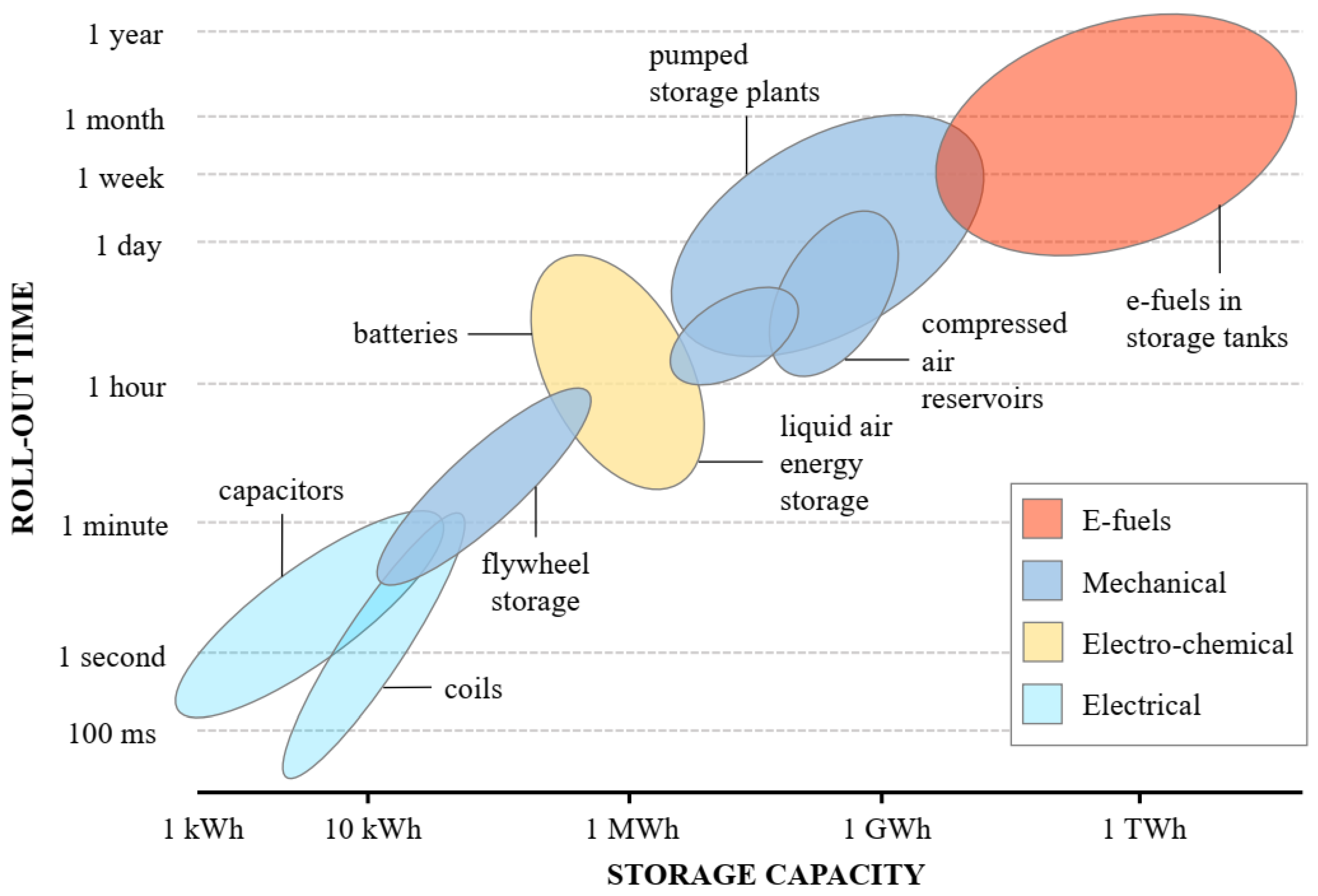
The sustainability of e-fuels critically depends on how hydrogen is produced, how electricity is generated, and the supply route of the carbon source used in the process. When produced using entirely renewable electricity and sustainable H2, e-fuels are highly sustainable (Figure 1 provides an overview of renewable technology, highlighting possible applications). Moreover, utilizing CO2 as a raw material for their synthesis ensures that their combustion does not generate additional GHG emissions [17,18]. Despite these potential benefits, there are significant challenges to address, including the costs and availability of raw materials necessary for large-scale production, and the localized pollution associated with their combustion [19,20,21].
E-fuels could serve as critical energy vectors, particularly in the transportation sector, by enabling the storage of electricity generated from renewable and non-programmable energy sources, which are expected to play a dominant role in the global energy transition [22]. However, the application and scalability of e-fuels are subject to various uncertainties, including technical challenges in production, economic viability, energy demand, and environmental impacts. These uncertainties raise questions about the practicality and feasibility of integrating e-fuels into the existing energy infrastructure. Several scientific studies discuss the opportunities for e-fuels, highlighting their advantages and drawbacks [15,16,23,24,25]. There is considerable confusion on this subject, exacerbated by the multitude of different terminologies and categories introduced in recent years to refer to e-fuels (power-to-X (PtX), power-to-liquid (PtL), power-to-gas (PtG), Gas-to-liquid (GtL), power-to-fuel (PtF), electrofuels, electronic fuels, and renewable fuels of non-biological origin (RFNBO)). The divergence of opinions within the scientific community regarding their potential to replace fossil fuels further complicates the landscape. While some experts advocate for e-fuels as a cornerstone of a future without emissions [26,27,28], others argue that they may not be competitive and that alternative solutions could more effectively achieve a clean energy system [29,30,31,32].
Given these varying perspectives, this study aims to systematically address the uncertainties surrounding e-fuels by providing a comprehensive review of current research and developments. The study examines various production pathways and technologies for e-fuels, evaluates their energy and environmental performance, and discusses their potential role in the future energy mix. By clarifying and categorizing the possible production technologies and paths, this review seeks to contribute to an informed discussion on the future of energy and the role that e-fuels might play in reducing global dependence on fossil fuels.

2. Raw Materials for E-Fuels Production

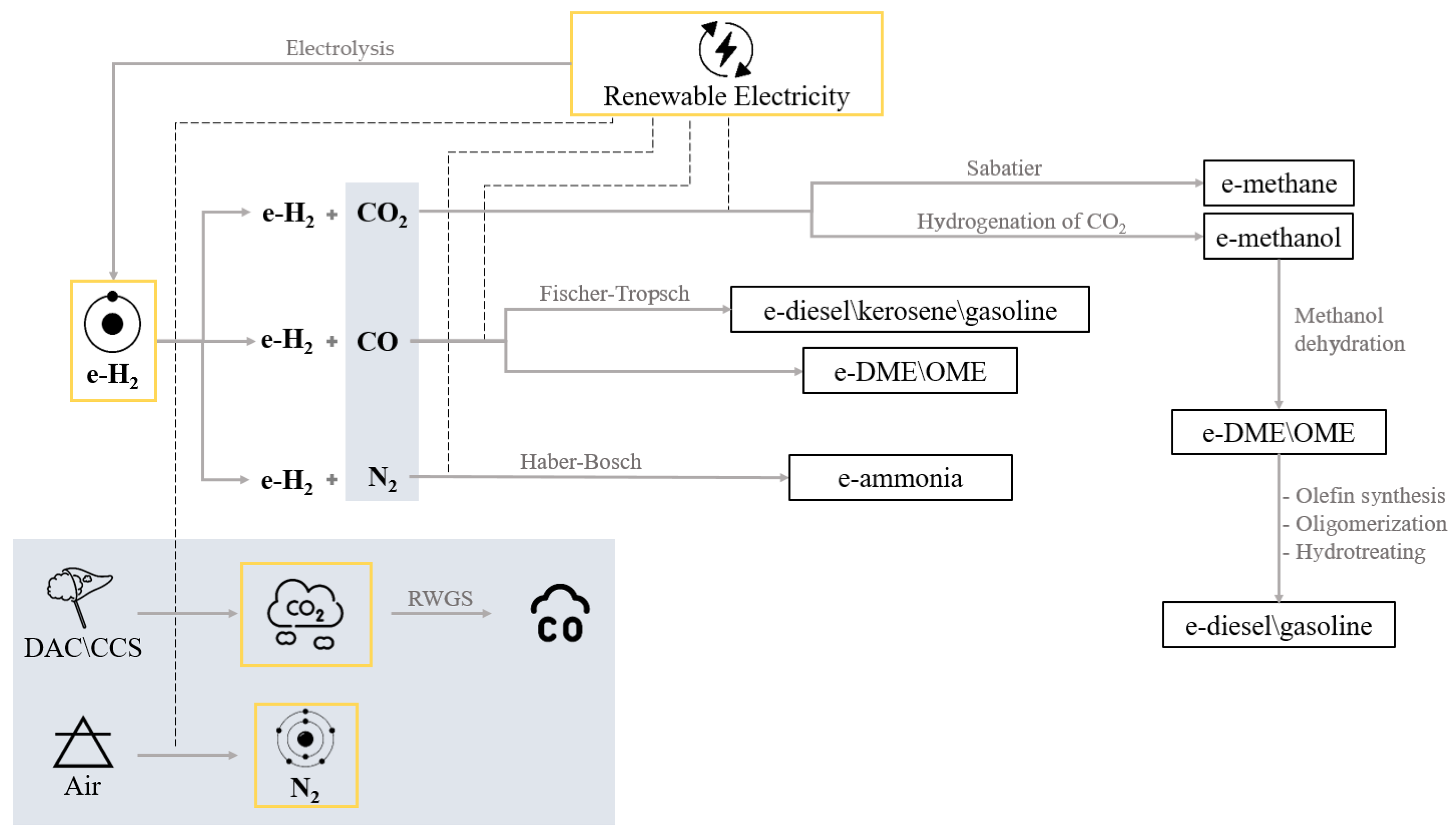
To summarize, e-fuels can be produced in different ways: H2 synthesis with CO2 to produce e-methane or e-methanol (from which e-DME/OME or e-diesel/gasoline can be obtained); H2 synthesis with CO to produce e-diesel/kerosene/gasoline or e-DME/OME (it is important to note that in processes involving H2 and CO, synthetic fuels can also be produced directly from syngas (a mixture of CO and H2, with traces of CH4 and CO2), but in this case, the term e-fuel or RFNBO is not properly used, as syngas is generally obtained from biomass); and H2 synthesis with N2 to produce e-ammonia. CO can be produced from CO2 through the Reverse Water Gas Shift (RWGS) reaction, while CO2 can be captured through carbon capture utilization and storage (CCUS) techniques or directly from the air (DAC). Regarding e-ammonia synthesis, N2 is obtained from the atmosphere [12,13].
Note that, to ensure the sustainability of the technology, all these processes require the use of renewable electricity, and H2 must be produced in renewable ways (Figure 2).
The following sub-paragraphs illustrate information from the literature about H2, CO2, N2, and electricity production, which are all involved in e-fuel syntheses.

2.1. Hydrogen

2.1.1. General Information

Hydrogen (H2) is the most abundant element in the universe, making up approximately 75% of all matter. On Earth, its abundance is much lower, being the 10th most abundant element, approximately 0.2% by mass overall, mostly in the form of H2O, which itself represents only about 0.03% of the Earth’s total mass [33]. The availability of molecular H2 is therefore very scarce, so H2 cannot be considered a primary energy source. However, compared to hydrocarbon fuels, the lower heating value (LHV) of 120 MJ/kg and its high energy yield make H2 an attractive energy carrier [34].
Currently, about 70–80 million tons of H2 are produced annually for industrial uses, mainly for refining petroleum products, for ammonia production, or as a raw material for fertilizers [13]. Its current use as a fuel is relatively marginal. H2 may be used to feed fuel cells (FCs) to produce electricity on-site for both industrial and transportation purposes [35,36,37]. In the latter case, vehicle traction would be fully electric, making this technology a direct competitor to battery electric vehicles (BEVs). A few vehicle models are already available on the market (including some buses) [38,39], but their diffusion is still very limited due to the complexity involved in fuel distribution and the refueling infrastructure needed [40]. Moreover, storing H2 is not simple, especially on-board a vehicle, due to critical weight and volume constraints [41,42]. H2 could be directly injected into the natural gas grid up to a maximum level of 15% by mass to lower the CO2 intensity of natural gas [43]. Its high flammability creates some challenges for direct combustion, together with a high flame temperature, which may lead to correspondingly high NOx values in the exhaust gases. Modifications are normally needed for combustion chambers [43,44,45].
H2 transport and storage face significant challenges due to its low volumetric density [41]. Compressed hydrogen, stored at pressures of 35–70 MPa, necessitates the careful selection of materials to avoid corrosion. Alternatively, hydrogen can be liquefied at −253 °C, although maintaining such low temperatures requires continuous energy input [46]. Cryo-compressed hydrogen merges these methods, storing hydrogen at cryogenic temperatures and pressures of 250–350 bar, achieving higher densities of approximately 80 g/L and reducing boil-off losses [47,48]. Other techniques for storage include metal hydrides, physical adsorption, liquid organic H2 carriers, and storage in salt caverns. Hydrogen forms chemical bonds with metals and metal alloys, resulting in metal hydrides [49]. Initially, hydrogen molecules dissociate into individual hydrogen atoms at the surface of the metal. These atoms then migrate deeper into the material, where they chemisorb into the metal or alloy’s structure [50]. This method offers safer and more moderate temperature and pressure conditions compared to gaseous or liquid forms. However, metal hydrides have slower reaction kinetics, mainly due to the strong chemical bonds that form between hydrogen and the metal or alloy and often require higher temperatures for hydrogen release [47]. Innovations in particle size reduction, alloying, and nanostructuring enhance their performance [51]. Complex metal hydrides, formed from elements like lithium, magnesium, and aluminum, provide higher storage densities. These hydrides are particularly promising due to their high hydrogen content and lower release temperatures but are limited by their reaction reversibility and sensitivity to environmental conditions [47,49,52]. Physical adsorption involves hydrogen being stored on the surface of materials through weak forces, offering rapid adsorption and desorption dynamics. This method is suited for applications where quick refueling is essential. Materials suitable for hydrogen storage through physical adsorption include microporous carbon structures, metal–organic frameworks, and zeolites. These adsorbents are generally advanced and possess extensive surface areas. Given that adsorption relies on surface interactions, a substantial surface area is essential for effective hydrogen storage [47,53]. Liquid organic hydrogen carriers (LOHCs) represent a versatile storage method, allowing hydrogen to be stored and released through chemical reactions with organic compounds. This technology leverages existing fuel infrastructure, facilitating easier integration into energy systems [47]. Lastly, large volumes of hydrogen can be stored in underground salt caverns at various pressure levels, offering a scalable solution for long-term storage. Air Liquide operates the world’s largest depot in Texas [54].
The main conventional methods for H2 production include [55] steam reforming and/or the partial oxidation of hydrocarbons [56,57,58]. Electrolysis is currently the second production option, favored not only for its sustainability when using electricity from renewable energy sources (RES), but also because it can produce a very pure H2 flow (more than 99.99% pure), which is crucial for certain final-use technologies, such as FCs [37].
H2 is commonly referred to using different “colors” depending on the production method. Four main types of H2 are identified: brown, gray, blue, and green [13]. Brown and gray H2 are produced from fossil fuels (coal and natural gas, respectively) and are the most common types on the current H2 market, but their production releases significant quantities of carbon dioxide into the atmosphere (brown H2 is substantially worse than grey H2 in this regard) [59]. Blue H2 shares its fossil origin with gray H2 and brown H2 but differs from them because carbon capture and storage (CCS) technologies are applied to its production process, thereby lowering its CO2 specific emissions substantially. Green H2, on the other hand, is produced from RES and can be considered potentially CO2-free. The main color codes for H2 are illustrated in Figure 3. In this study, green H2 produced through the electrolysis of water is referred to as e-hydrogen (e-H2).

2.1.2. E-Hydrogen

Different types of electrolyzers facilitate the electrolysis reaction. In this process, electricity is consumed to split the water molecules into hydrogen and oxygen.
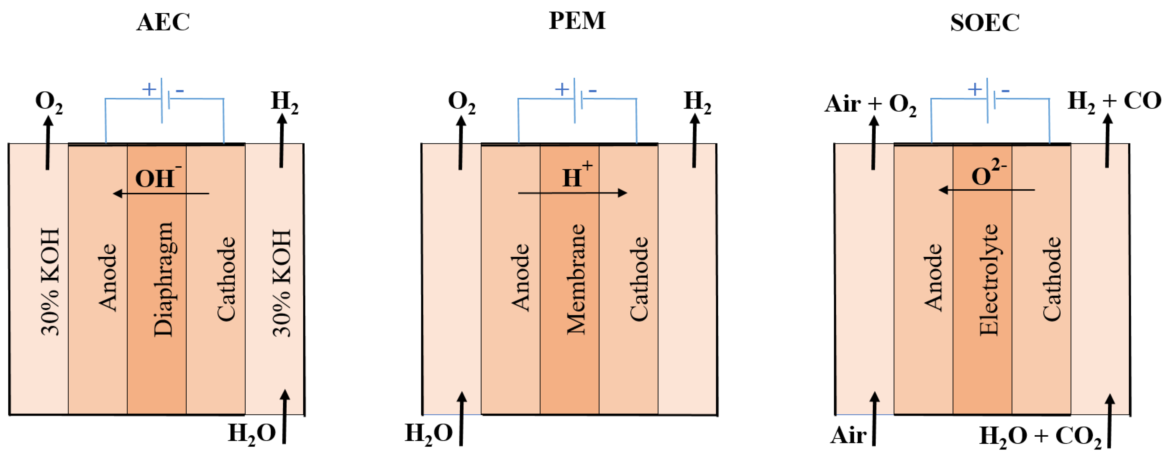
Among the various available technologies, illustrated in Figure 4, there are alkaline electrolyzer cell (AEC) systems, which represent a well-established and widely known choice. In these systems, electrolytes are aqueous solutions (such as potassium hydroxide (KOH) or sodium hydroxide (NaOH) dissolved in water), immersed in electrodes made of metallic material. OH ions are transferred between the cathode and anode. A diaphragm, permeable to the electrolyte, prevents the mixing of hydrogen and oxygen, keeping them separated on the cathodic and anodic sides, respectively. Gas and electrolyte streams exiting the cathode and anode are sent to two liquid–vapor separators, where the residual electrolyte is recirculated while the gases can be further purified and sent to external uses. Although AECs can produce high-purity e-H2 at a relatively low initial cost, they can cause corrosion and require some time to start, making this technology less suitable for handling fluctuations in energy demand. Therefore, despite being relatively simple and economical, they are not as efficient as other types of electrolyzers [60].
An alternative is represented by proton exchange membrane (PEM) technology. In this technology, the water molecule splits at the anode into oxygen, electrons, and protons (H+). The protons traverse the electrolytic membrane to reach the cathode, where they are reduced to form e-H2. PEM technology is a highly efficient process and has the capacity to handle variable load profiles, typical of RES (non-programmable). However, it requires the use of expensive materials for electrodes, increasing the overall system cost [61].
Finally, solid oxide electrolyzer cell (SOEC) technology involves the use of steam at the cathode, allowing water to be reduced to produce e-H2 and O2− anions that move towards the anode, where the oxygen molecule forms [62]. SOEC technology is highly efficient at high temperatures, offering a potential advantage in overall energy efficiency, particularly when integrated with high-temperature heat sources, such as solar thermal or industrial waste heat [63]. Although earlier concerns were raised about the high energy consumption and costs associated with the SOEC process, these issues are being addressed by ongoing research and development. Recent advancements in materials science have led to the use of more cost-effective materials for the anode, cathode, and electrolyte, reducing the overall capital costs of SOEC systems [64,65]. Furthermore, the technological development of SOECs has advanced significantly in recent years, with improvements in durability and efficiency making them a more viable option compared to other types of electrolyzers [66].
Among the three different technologies, currently, AEC is the most widely used [67]. It is worth noting that the sustainability of the process depends on the source of electrical energy. When using renewable electricity, the process is “GHG free” (no emissions of greenhouse gas). Currently, only 4% of total H2 is produced from renewable sources [68]. This is due to a number of barriers that avert the full contribution of e-H2 in the energy transition, including the lack of devoted infrastructure (e.g., transport and storage infrastructure), issues associated with the production stage of electrolysis such as energy losses, lack of value recognition, ensuring sustainability, and high production costs [14].
E-H2 can be considered as an e-fuel in itself or as a necessary raw material for producing all other e-fuels. E-H2 can be used as an effective fuel both in industry and residential processes, as well as in transportation applications (eventually also in mixtures with CH4), reducing the CO2 intensity of all these applications, which normally make use of fossil and much heavier hydrocarbons [43,44]. One of the main challenges in e-H2 production is its cost, which is closely linked to the cost of electricity and the efficiency of the electrolyzers. Currently, H2 is primarily produced from fossil fuels, making it fossil-derived and carbon-intensive. However, as RES becomes more widely available and cost-effective, H2 production is likely to become more sustainable and affordable, allowing e-H2 to play an increasingly important role over time [20]. Several global energy organizations are focused on reducing e-H2 production costs and improving the efficiency of existing systems. An example of such an organization is IRENA [69]. Major industrial H2 producers worldwide include ITM Power PLC, Linde PLC, Engie SA, Air Liquide SA, and The Messer Group GmbH [13].

2.2. Carbon Dioxide

The emission of CO2 can come from natural sources and human activities. Natural sources include the exchange of oceanic atmospheres (42.84%), soil respiration and decomposition (28.56%), animal and plant respiration (28.56%), and a small portion from volcanic eruptions (0.03%) [70,71,72]. In addition to natural sources, CO2 can also be released into the atmosphere from human sources (anthropogenic CO2). Combustion gases emitted from fossil fuel power plants (coal, oil, and natural gas) account for 87%, land uses such as deforestation and agriculture account for 9%, and other carbon-intensive industries such as cement production and transportation account for the remaining 4%. Although human sources produce fewer CO2 emissions than natural sources, human activities disequilibrated the natural pre-industrial carbon cycle, leading to an increase in atmospheric CO2 concentration [73].
The production of e-fuels requires carbon dioxide that can be obtained in several ways. The most interesting are carbon capture utilization and storage (CCUS) techniques from industrial processes and direct capture from the air (DAC). The CO2 emitted during the combustion of e-fuels is theoretically equal to the CO2 absorbed due to its production [14,15,74].

2.2.1. CCUS

Carbon capture utilization and storage (CCUS) is the process of capturing emitted CO2 and storing it in large sites to prevent its release into the atmosphere and for potential utilization. The CCUS process involves three main steps: CO2 capture, compression and transport, and storage until its utilization. Current CCUS technologies can contain 85–95% of the CO2 produced by a power plant and can reduce current emissions by about 80–90%. Integrating it into power plants is an energy-intensive process with 10–40% additional energy consumption associated with CO2 capture [75]. In 2022, the CO2 capture capacity through CCUS techniques was 244 Mt(CO2)/year [76].
Table 1 shows the differences between the three CCUS technologies: post-combustion, pre-combustion, and oxyfuel combustion.
Post-combustion is applied in large-scale fossil fuel combustion plants where CO2 from the flue gas stream is separated after the combustion process, usually using a chemical absorption process. Then, CO2 is sent to a storage tank while the flue gas is released into the atmosphere. This method is a mature technology and is currently used in many industrial applications, particularly in the food and beverage industry. Compared to other capture methods, post-combustion is the most common with easy adaptation for CO2 capture from existing coal-fired power plants [78].
In the pre-combustion approach, the method is usually applied in natural gas plants where fossil fuel is gasified (partially oxidized) at a high temperature and pressure to produce syngas consisting of carbon monoxide (CO) and hydrogen. CO reacts with steam (H2O) in a catalytic reactor to produce CO2 and additional H2 (water gas shift reaction). The resulting CO2 is then separated prior to combustion by a physical or chemical adsorption process, and the remaining pure H2 is used as fuel in many applications, e.g., gas turbines, engines, FCs, and boilers [79]. This type of technology is characterized by the ease of CO2 separation due to high pressure and high concentration of CO2 being removed in addition to low water consumption. All these factors make the technology less energy-intensive, although there are some energy losses, and the cost of integrated gasification combined cycle (IGCC) is more expensive than the cost of conventional coal combustion plant [77].
Oxyfuel combustion is still under development; the fuel is burned using pure oxygen instead of air, producing a nitrogen-free flue gas that contains only steam and CO2. Therefore, steam can be easily separated by condensation and cooling to produce a pure CO2 stream. Other advantages of oxyfuel combustion are high-efficiency carbon capture, high air separation, and small equipment size [77].
Recent technologies for carbon capture and separation techniques including absorption, membranes, cryogenic distillation, gas hydrates, and chemical loops that are all used for the separation of CO2 present in flue gas to be sent for transport and storage are discussed in detail in Refs. [77,79].

2.2.2. DAC

Several technologies for capturing CO2 from air are under development [80]. The challenge lies in the low CO2 concentration in air, about 0.04% [81]. Investigated technologies include absorption with electrodialysis, absorption with calcination, and adsorption/desorption (temperature swing adsorption, TSA) [27,82,83,84].

Absorption and Electrodialysis

CO2 extraction from air is achieved by absorption with sodium hydroxide (NaOH) or potassium hydroxide (KOH), forming Na2CO3 or K2CO3. These carbonates are then decomposed by electrodialysis, a method using electrical voltage and selective membranes to separate ions based on charge [85]. The process involves adsorption, stripping, and electrodialysis [27]:
CO 2 + 2 NaOH Na 2 CO 3 + H 2 O
Na 2 CO 3 + H 2 S O 4 N a 2 S O 4 + C O 2 + H 2 O
N a 2 S O 4 + 2 H 2 O 2 N a O H + H 2 S O 4
With a current density of 100 mA/cm3, power consumption for the entire process, including the fan, is about 430 kJ per mole of CO2 [27,85].

Absorption and Calcination

The process developed by the Canadian Company Carbon Engineering consists of the absorption of CO2 with potassium hydroxide (KOH), the formation of CaCO3 (adding CaO to K2CO3), the regeneration of CaCO3 by calcination, and the subsequent conversion to Ca(OH)2 [86]. The absorption, regeneration, calcination, and regeneration reactions are described by
2 K O H + C O 2 K 2 C O 3 + H 2 O
K 2 C O 3 + C a ( O H ) 2 K O H + C a C O 3
C a C O 3 C a O + C O 2
C a O + H 2 O C a ( O H ) 2
Carbon Engineering reports a natural gas consumption of about 10 MJ per kg of CO2. The theoretical minimum heat requirement for the calcination reaction is about 4.1 MJ per kg of CO2 [85]. The calcination process requires very high temperatures (900 °C) to convert CaCO3 to CaO and recover the CO2 [87]. In 2015, Carbon Engineering began operations at its complete end-to-end pilot plant located in Squamish, Canada, capturing about 1 ton of atmospheric CO2 per day. In 2017, the company incorporated fuel synthesis capacity into the DAC pilot plant and converted the captured CO2 to fuel for the first time. Carbon Engineering’s technology is now being scaled up for commercial markets, with claims that individual DAC plants could capture 106 tons of CO2 per year, offsetting the emissions of about 250,000 cars by sequestering CO2 or using it as feedstock to produce e-fuels [86].

Adsorption and Desorption (TSA)

Climeworks, a Swiss company, uses an adsorption/desorption cycle to extract CO2 from air. The CO2 is chemically bound to an amine-based solid sorbent (in contrast to most adsorption processes, the Climeworks process uses chemisorption instead of physisorption) [88]. The regeneration of the sorbent is carried out by low-temperature heat (90 °C). The TSA process captures CO2 in a filter and releases it using low-grade heat at about 100 °C. The CO2 is then collected as a concentrated gas for supply to customers or for negative emission technologies. The CO2-free air is released back into the atmosphere and the filter is reused several times, lasting for several thousand cycles. The plant’s power consumption averages 0.9 MJ per kg of CO2 [89].

2.3. Nitrogen

Nitrogen, combined with hydrogen, is a reactant to produce ammonia. When using e-H2, the resulting ammonia is e-NH3. As the main component of air, nitrogen is separated using three commercial technologies [90]: cryogenic distillation with air separation units (ASU) [91,92]; separation by membrane (permeation) [93]; and pressure swing adsorption (PSA) [94].
Cryogenic distillation is the most cost-effective method, with specific consumption at 0.11 kWh/kg(N2) [95,96]. The nitrogen separation consumption has a minimal impact on overall ammonia production, achieving efficiencies above 0.5 in existing large-scale plants [97]. Producing 1 kg of ammonia requires 0.18 kg of H2 and 0.82 kg of N2 [32]. Combining this process with SOEC can improve coupling with ammonia synthesis, achieving higher efficiencies (up to 0.7) due to thermal integration, though SOEC technology is still in its early stages [98].
Nitrogen demand spans multiple sectors [99,100]. Key industries include the chemical industry (where it is used as an inert gas in reactions or for purifying and separating chemicals); agriculture (where it is essential for fertilizer production); the food industry (where it is used for food preservation); the metallurgical industry (where it is involved in heat treatment, rapid cooling, metal purification, and preventing oxidation during melting); the electronics and semiconductor industry (where it is crucial for producing semiconductors and electronic devices); the medical industry (where liquid nitrogen is used for cryopreservation, cooling, and cryosurgery); the power industry (where it prevents corrosion and oxygen formation in power plant cooling water); and the pharmaceutical industry (where it protects oxygen-sensitive reagents and is used for packaging and preserving pharmaceuticals).
Future nitrogen demand is uncertain and will depend on global economic trends, industrial and technological advancements, and the evolving needs of various industries [99].

2.4. Electricity Consumption

Electricity is required in all stages of e-fuel production: from electrolysis for hydrogen, to nitrogen separation from air, to CO2 capture, and the synthesis of e-fuels.
Hydrogen production via electrolysis requires energy consumption between about 45 and 73 kWh/kg(H2) [32,101,102]. Nitrogen separation using cryogenic distillation consumes about 0.11 kWh/kg(N2) [95,96]. To produce 1 kg of ammonia, approximately 9 kWh is required for hydrogen and 0.09 kWh for nitrogen [32]. Energy consumption for separating nitrogen from air is less than that required for hydrogen production. CO2 capture also requires significant energy; for CCS techniques, the increase in energy consumption can range from 10% to 40% [75]. For DAC technologies, the energy consumption required for absorption/electrodialysis and absorption/calcination, the most mature technologies, is about 1.45 kWh/kg(CO2) [32,82,83]. The final stage, fuel synthesis, has a relatively low energy consumption of about 0.50 kWh/kg of final product for FT synthesis [103].
Hydrogen production by electrolysis is the most energy-consuming process among all e-fuels [104], but the overall energy consumption for e-fuels production is still significant. This necessitates an increase in renewable energy demand to ensure the GHG emission neutrality of e-fuels.
Currently, only about 20% of the world’s electricity is produced from renewable sources [105]. The average global carbon intensity of electricity production in 2022 was 438 g(CO2)/kWh, with significant variation among countries [2,106]. For e-fuel production using the average electricity intensity, the GHG intensity would be about three times that of liquid fossil fuels [107].
E-fuel plants require cost-competitive renewable electricity and high full-load hours of operation to be economically efficient. Frontier Economics estimates that e-fuel plants need 3000 to 4000 full-load hours per year [108]. In Germany, the current shortfall is about 1500 h per year. Only a few areas in Europe have renewable energy supply exceeding demand, and even then, not regularly. The excess renewable energy production in Europe is about 10% per year and is expected to increase over time. Therefore, adequate renewable power plant capacity must be built before e-fuel production can significantly contribute to global GHG emission reduction targets. These plants can be located in Europe (e.g., offshore wind) or in areas with cheap, abundant RES (e.g., North Africa and the Middle East with onshore wind turbines and photovoltaics) [108].
A target of supplying 50% of European aviation fuel from e-fuels by 2050 would require renewable electricity generation equivalent to a quarter of the current total EU electricity generation. Providing 50% of truck fuel in 2050 would require additional renewable electricity generation equivalent to more than one-third of the current EU electricity supply [104].
The investment required to secure large-scale fuel production would therefore be substantial. The prerequisite of having renewable electricity, the resource intensity required, and the cost of expanding e-fuel production are reasons why some experts see e-fuels as a long-term climate solution only for a “niche” market and thus for relatively small demands [27]. Further studies could help faster entry into the e-fuel economy. An example is accurately described in ref. [109] in which new technologies are studied to ensure the efficient production of e-fuels despite the intermittency issue of renewable electricity.

3. E-Fuels Types

3.1. E-Methane

Methane is the main component of natural gas and has lower carbon dioxide emissions compared to other hydrocarbon-based fuels, making it a cleaner and simpler fuel with fewer local pollutants [110]. However, methane emissions must be carefully managed, as methane has a global warming potential (GWP100) of 28 kg CO2 per kg CH4, meaning it is 28 times more potent than CO2 over a 100-year period [111].
Currently, methane is primarily sourced from natural deposits or through fracking technologies, producing fossil methane. Fracking, particularly in sub-sea contexts, poses significant risks due to potential volatile methane emissions over the long term.
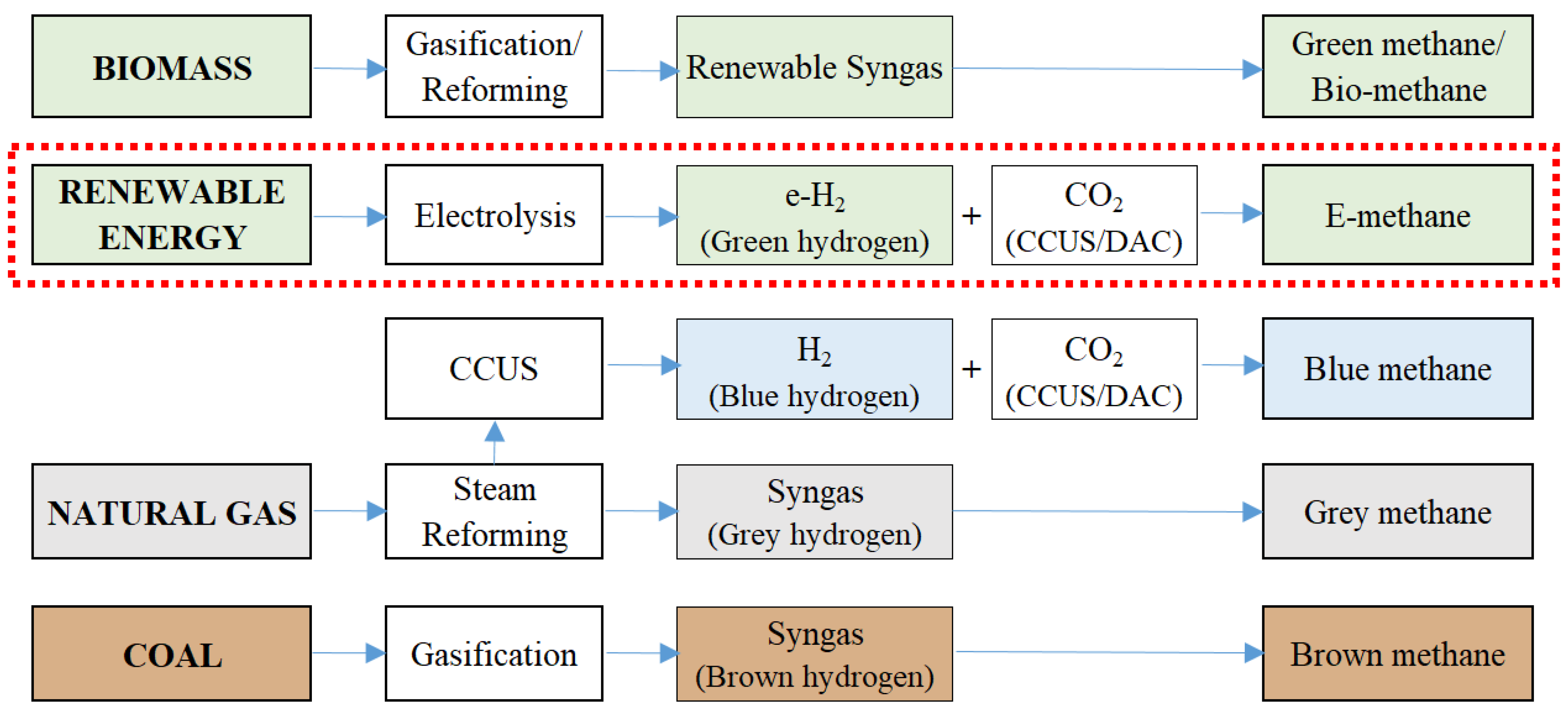
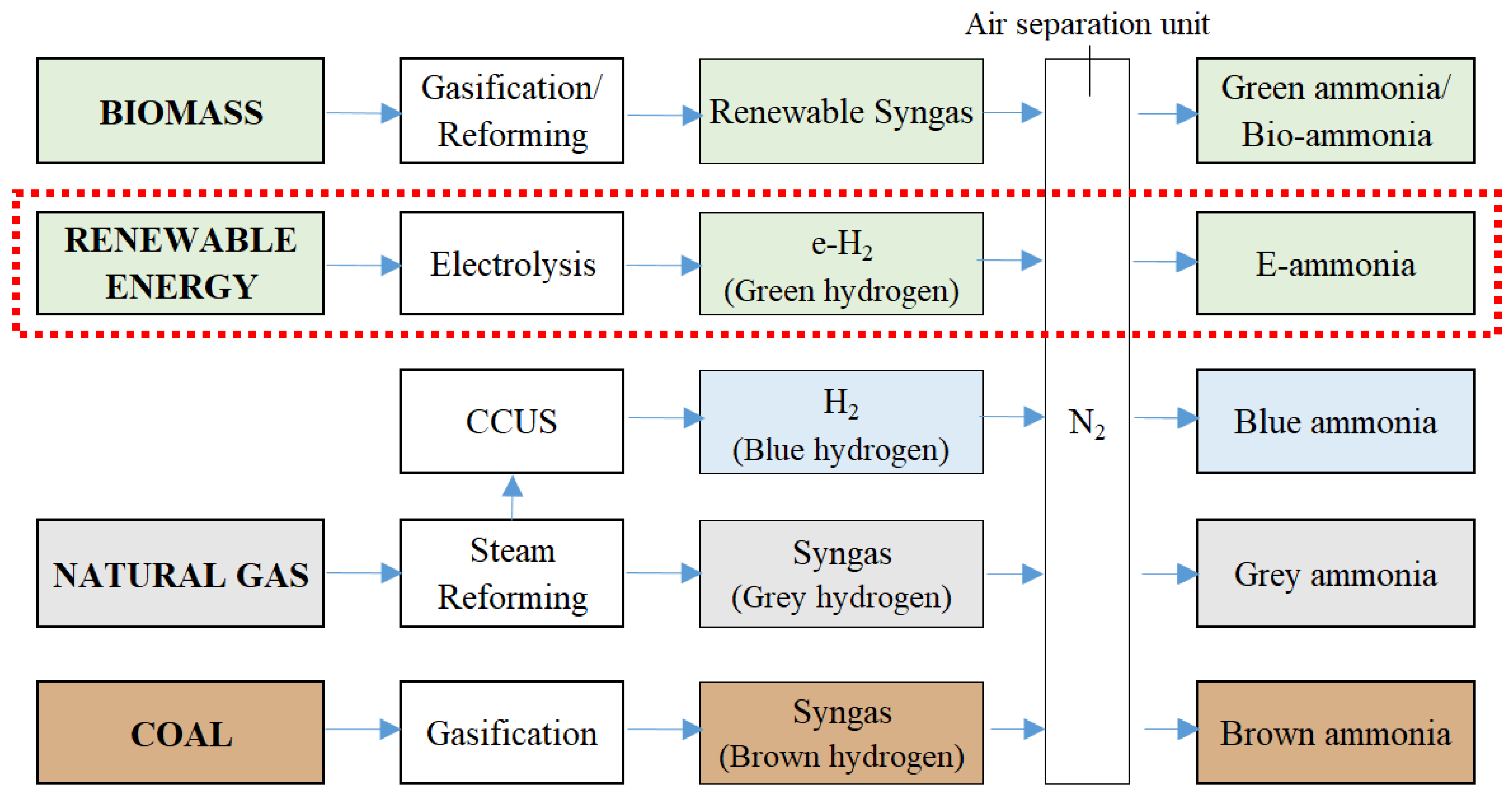
Synthetic methane, or e-methane, can be produced through the methanation of CO2, where hydrogen reacts with carbon dioxide. If the hydrogen is produced using RES, the resulting methane is termed e-methane. The various production pathways for methane are identified by colors (Figure 5), with gray and brown methane representing fossil sources, which are currently the most economical routes [14].
E-methane production involves combining electrolysis with methanation [112,113]. Hydrogen is produced from water electrolysis, and this hydrogen reacts with CO2 in a reactor, following the Sabatier reaction:
C O 2 + 4 H 2 C H 4 + 2 H 2 O
During this process, CO2 is compressed to 5–50 bar and introduced into a methanation reactor at temperatures between 250–400 °C, converting it into CH4 [114,115].
The produced e-methane can be injected into the existing natural gas grid, used as fuel for natural gas vehicles, or utilized in industrial applications and electricity generation. This process, while straightforward, requires significant amounts of CO2 (5.5 kg for every kg of H2), which is often challenging to obtain due to the distance between CCS systems and renewable plants, increasing CO2 transport costs [116].
E-methane production allows for the storage of renewable electricity in chemical form, making it available when needed. It also offers a solution to reduce GHG emissions by utilizing CO2 when renewable electricity is used for hydrogen production and fuel synthesis.
An example of this technology in practice is the Audi e-gas project in Germany, the world’s largest PtG facility for e-methane production [117]. This facility produces approximately 1000 tons of synthetic methane annually, which is distributed through existing infrastructure to compressed natural gas refueling stations.

3.2. E-Methanol

Methanol (CH3OH) is the simplest alcohol and is mainly produced from fossil fuels (85% from natural gas and around 15% from coal). Global production is 98 million tons per year, emitting 0.3 gigatons of CO2 annually, which is about 10% of the chemical sector’s total emissions. Methanol demand is projected to increase to 500 million tons by 2050, potentially releasing 1.5 gigatons of CO2 per year if fossil fuels continue to be used exclusively [118].
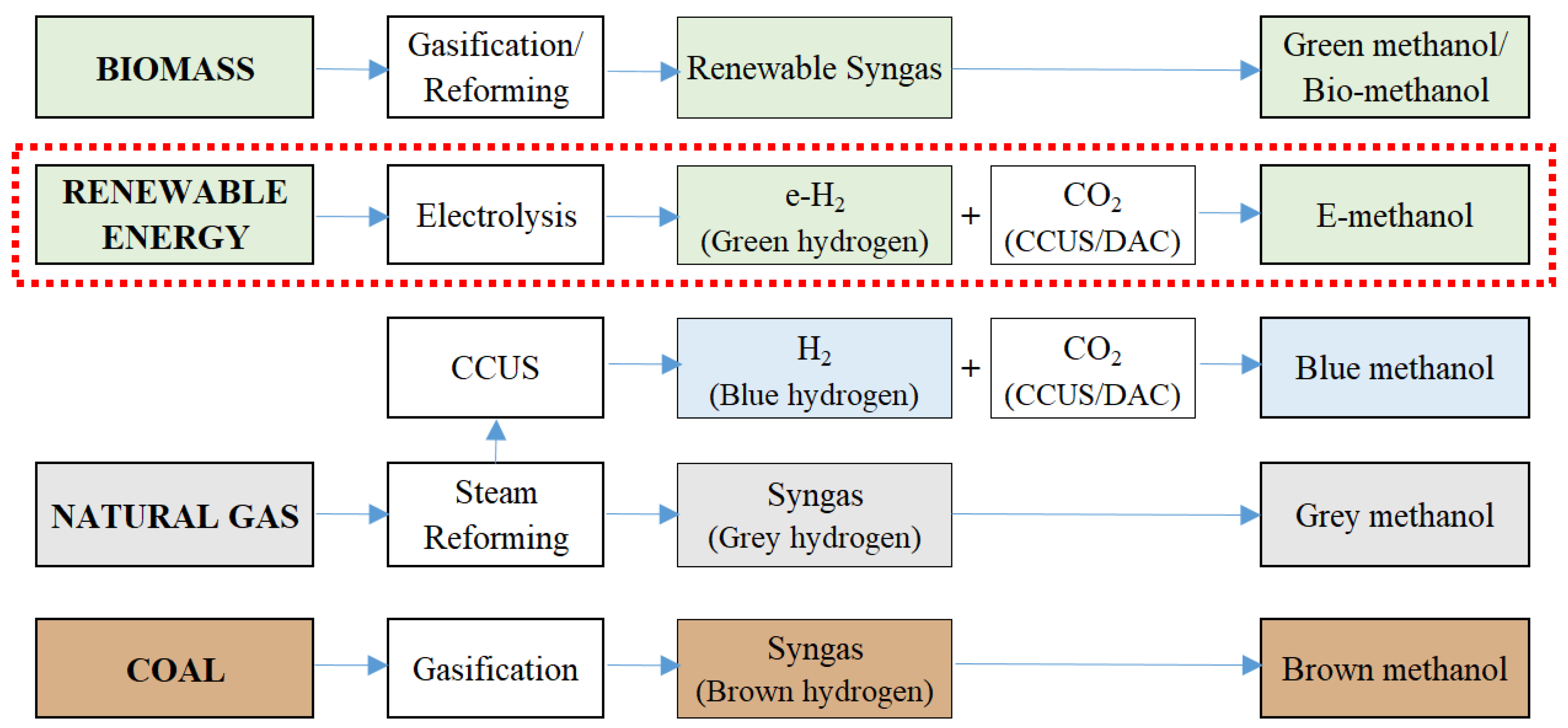
Methanol can be produced from various carbon sources, including natural gas, coal, biomass, and CO2 captured from industrial emissions or directly from the air. Figure 6 illustrates the main production pathways of methanol from different feedstocks. Only a small fraction of methanol (0.2%) is derived from renewable sources [119,120]. Renewable methanol (green methanol) can be produced from biomass or e-methanol pathways, using sources such as agricultural waste, landfill biogas, and municipal solid waste.
Currently, methanol is primarily produced from syngas using Cu/ZnO/Al2O3 heterogeneous catalysts at high temperatures (200–300 °C) and pressures (50–100 bar) [121,122]. E-methanol is produced by CO2 catalytic hydrogenation in an adiabatic fixed-bed catalytic reactor. The catalysts typically contain Cu and Zn, along with additives like Al, Zr, Cr, Si, B, and Ga [123]. Pre-heated hydrogen and carbon dioxide are catalytically converted into methanol by means of the CO2 hydrogenation (9), reverse water–gas shift (10), and CO hydrogenation (11) reactions [124,125]:
C O 2 + 3 H 2 C H 3 O H + H 2 O
C O + H 2 O H 2 + C O 2
C O + 2 H 2 C H 3 O H
The process operates between 250 and 300 °C and 50 to 100 bar, using Cu/Zn/Al-based catalysts [126,127,128,129].
Another e-methanol production process involves the direct conversion of e-methane. This method uses water as an oxidizing agent with a copper bed containing zeolite as a catalyst, producing hydrogen as a byproduct. Direct conversion pathways are still in early development and require 5 to 20 years for industrial feasibility [130].
Methanol has about half the volumetric energy density of gasoline. It has a high octane number and a low cetane number, making it suitable for spark-ignition engines with minimal modifications. Methanol is used to produce chemicals such as formaldehyde, dimethyl ether, and methyl tertiary-butyl ether (MTBE) and is a solvent and clean synthetic fuel for transportation, industrial boilers, wastewater treatment, and electricity generation. Derivatives like dimethyl ether (DME), synthetic gasoline, or kerosene can also be produced from methanol. China is the largest producer and consumer of methanol, with national standards for M15 and M85 fuels, containing up to 15% and 85% methanol, respectively [131].
Bio-methanol and e-methanol are already produced globally by demonstration units [118]. One of the first large-scale CO2-to-methanol conversion processes dates back to the early 1990s, developed by Luigi AG. An operational e-methanol plant in Iceland utilizes CO2 from geothermal power plants with an efficiency of 0.42 [132]. The MefCO2 pilot plant in Germany (2019) uses CO2 from a coal-fired power plant and hydrogen from a PEM, producing 500 tons of e-methanol annually [133].

3.3. E-DME/OME

Dimethyl ether (DME), also known as methoxymethane (CH3OCH3), is the simplest form of ether. DME is relatively easy to use; although it is gaseous at ambient conditions, it can be easily liquefied and stored at low pressure, similar to Liquefied Petroleum Gas (LPG). This increases its volumetric energy density, making it particularly appealing for internal combustion engine (ICE) applications [134].
Originally a byproduct of high-pressure methanol synthesis, DME is now primarily produced through the dehydration of methanol in a “two-stage synthesis” process. It can also be directly synthesized from syngas via the Fischer–Tropsch (FT) process. The goal of methanol dehydration is to convert CO2 into DME using hydrogen [135]. The synthesis involves two reaction steps: the reduction of CO2 to methanol and the dehydration of methanol to DME:
C O 2 + 3 H 2 C H 3 O H + H 2 O
2 C H 3 O H C H 3 O C H 3 + H 2 O
The overall reaction is:
2 C O 2 + 6 H 2 C H 3 O C H 3 + 3 H 2 O
One of the main undesired reactions is the RWGS: An endothermic reaction that reduces CO2 while simultaneously producing H2O and CO according to the equation [136,137]
C O 2 + H 2 C O + H 2 O
RWGS requires high operating temperatures (300–800 °C), determined by the chosen catalyst (usually copper-based) and specific process conditions such as syngas composition [138].
For direct synthesis from syngas, two possible pathways are described by the following reactions [32]:
3 C O + 3 H 2 C H 3 O C H 3 + C O 2
2 C O + 4 H 2 C H 3 O C H 3 + H 2 O
Both reactions are employed in commercial plants [125]. In this process, in addition to hydrogen, carbon monoxide is used, which is easily obtained from CO2 through the RWGS reaction.
The direct hydrogenation of CO2 into DME has been studied, but its stage of technological development remains limited [139].
DME oligomers constitute a group of oxymethylene ethers (OMEx). The term “oligomer” implies that OMEx consists of a chain of x repeated residual units of the DME ester [140]. DME is considered OME0. OME1 signifies the addition of another ester block to the initial DME block. For OME2, two additional ester blocks are added to the chain, and so on for other oligomers. OMEx has a higher molecular mass than DME, contributing to changes in physical properties, such as higher boiling points or different states at lower temperatures.
DME shares similarities with LPG, while OMEx exhibits physical and chemical properties similar to diesel [141,142]. DME can also be converted into other chemicals and dimethyl sulfate (DMS), which is used in the production of detergents and household products [143]. The LHV of DME is lower than that of diesel. OMEx fuels have no carbon–carbon bonds and a high oxygen content. Their volumetric energy density is low but exceeds that of methanol. OME fuels are not compatible with existing infrastructures and deviate from current European diesel specifications (EN 590, EN15940); therefore, they may only be used in small quantities. Additionally, the compatibility of current engine materials with OMEx is unknown, and the approval for their use in existing vehicles would be required. For high concentrations, the engine and fuel system would need complete adaptation [141].
In principle, DME could be used as an LPG blend for spark-ignition engines; however, its low octane number makes this challenging. It is more commonly considered an alternative to diesel for use in compression-ignition engines [144]. DME produces significantly lower levels of CO2 emissions compared to diesel and may reduce pollutants in the engine exhaust (NOx, SOx, and particulate matter) [145]. Moderate engine and injection system modifications are needed for DME use in vehicles, and a dedicated recalibration of the engine should be performed. So far, only small commercial vehicle fleets (buses and heavy-duty vehicles) have utilized DME as a transport fuel, particularly in urban contexts to address air quality concerns. DME can also be used in many other applications beyond transportation, both in combustors for heating applications and in thermoelectric power plants. Its direct use in FC devices is still in the early laboratory stages [146].
DME and OMEx are easy to transport and store. Despite the potential role of these fuels, especially in the heavy-duty sector, most publications do not consider e-DME and e-OME as alternative components to current fuels. Ford is currently leading a research project, co-financed with the German government, to test vehicles running on OMEx and DME. As of 2022, key players dominating the DME production market are Korea Gas Corporation, Zagros Petrochemical Company, Jiutai Energy Group, Mitsubishi Corporation, and Nouryon [13].

3.4. E-Diesel/Kerosene/Gasoline

Technologies for producing e-diesel, e-kerosene, and e-gasoline are often referred to as PtL applications. These technologies typically utilize hydrogen and carbon monoxide as raw materials to generate liquid fuel via the Fischer–Tropsch (FT) process. Alternatively, they can use methanol as an intermediate product from other reactors, converting it to gasoline and/or diesel through processes known as methanol-to-gasoline (MTG) or methanol-to-olefin-to-gasoline and diesel (MOGD). In the MTG process, the following reactions occur [147]:
DME synthesis:
2 C H 3 O H C H 3 O C H 3 + H 2 O
Olefin synthesis:
C H 3 O C H 3 ( C H 2 ) 2 + H 2 O
Oligomerization:
0.5 n ( C H 2 ) 2 C n H 2 n
Hydrotreating:
C n H 2 n + H 2 C n H 2 n + 2
The conversion of methanol to olefins was first achieved in 1970, alongside the similar process of converting methanol to gasoline [148]. In 2011, an MTG plant in China had a capacity of about 3000 tons per day [149]. Today, the MTG process is provided by ExxonMobil and Haldor Topsoe (TIGAS: Topsoe Improved Gasoline Synthesis). Air Liquide offers a methanol-to-olefin process to produce propylene (methanol-to-propylene—MTP), which is an intermediate step for producing gasoline, kerosene, and diesel [147].
The FT process, historically used in Germany to convert solid fossil fuels into liquid hydrocarbons as an alternative to petroleum, can also produce fuels from non-fossil feedstock using electricity [150,151]. This chemical reaction synthesizes various liquid hydrocarbons, including diesel, gasoline, and aviation fuel [152,153,154]. The process involves carbon monoxide (CO) and hydrogen (H2), which can be supplied separately or as syngas from gasification. When using H2 and CO separately, CO2 obtained through CCUS or DAC can be the source of CO via the RWGS reaction. An alternative to RWGS is syngas production directly from CO2 and H2O through co-electrolysis, typically in a SOEC [155]. Subsequently, CO and H2 are converted into liquid hydrocarbons and combustible gases through FT synthesis by a series of reactions summarized by the following general equation [32]:
( 2 n + 1 ) H 2 + n C O C n H 2 n + 2 + H 2 O
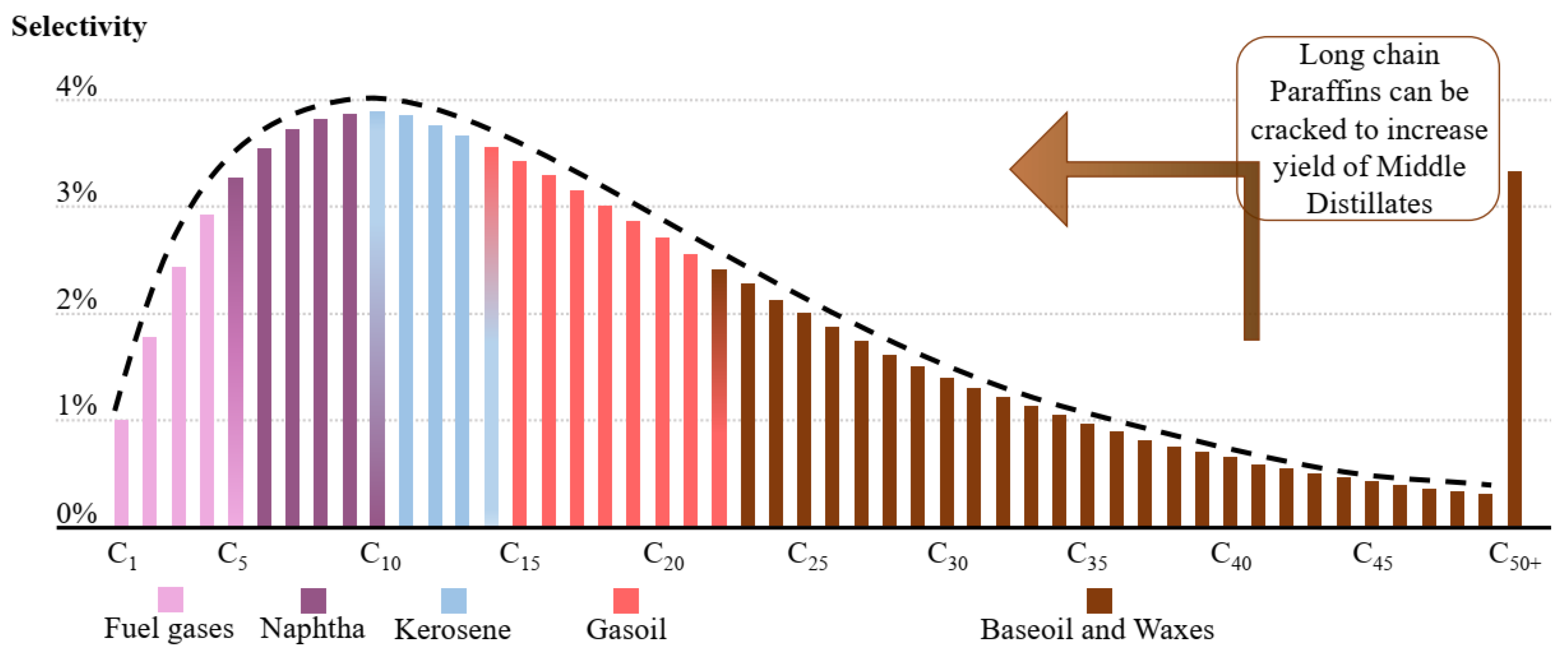
This process occurs in reactors at high temperatures (190–350 °C) and pressures (20–50 bar) [156], typically using iron or cobalt-based catalysts [157]. The products are classified based on hydrocarbon chain length [158], as shown in Figure 7.
Several factors influence the type of products synthesized, including temperature, catalyst type, and syngas composition. Elevated process temperatures (320–350 °C) favor the production of low-molecular-weight hydrocarbons, while lower temperatures (190–270 °C) favor high-molecular-weight hydrocarbons [103].
Typical components of an FT catalyst include [161,162,163] active metals for FT (Co, Fe, Ru), promoters for reduction (Pt, Ru, Pd, Re, Cu), promoters for activity/selectivity (K, Zr, rare earth elements), and refractory oxides used as supports or structural promoters (Al2O3, SiO2, TiO2). The catalyst type plays a significant role: iron-based catalysts are preferred due to their lower cost and greater flexibility in syngas composition (acceptable H2/CO ratio: 0.5–2.5). Conversely, cobalt-based catalysts offer longer lifespans but at a higher cost, requiring lower temperatures (190–240 °C) and a more restricted H2/CO ratio (2.0–2.3) [164]. For gasoline production, a high-temperature iron-based catalyst is most suitable, while for maximizing diesel production, a cobalt-based catalyst is preferable [165]. Traditionally, Co- and Fe-based catalysts have been used for commercial-scale FT processes, whereas precious metal-based catalysts (e.g., nickel- and ruthenium-based) that are catalytically more active have not yet found a practical role in industrial applications [125]. Other relevant catalysts include porous metal oxides (e.g., zeolite and aluminum oxide) with large specific surfaces used as carriers for the catalyst. The use of Co-based catalysts is limited to operating conditions with relatively low temperatures (200–240 °C), but Fe-based catalysts can be used over a wider range of operating temperatures (200–240 °C to 300–360 °C) [166]. Recent laboratory-scale advancements in catalysts for FT synthesis include combining Fe-based catalysts with transition metal promoters (e.g., Fe–Mn–K) for high conversion rates and high selectivity to Sustainable Aviation Fuel (SAF) [167]. The catalytic performance using three transition metal promoters (Na-, K-, and Cs-based) was found to be similar, but the K-based metal promoter (Fe–Mn–K catalyst) showed high CO2/H2 conversion rates and higher selectivity in longer-chain hydrocarbons (47.8% for C8–C16) than the selectivity from Na- and Cs-based metal promoters (44.4% and 44.0%, respectively) [133].
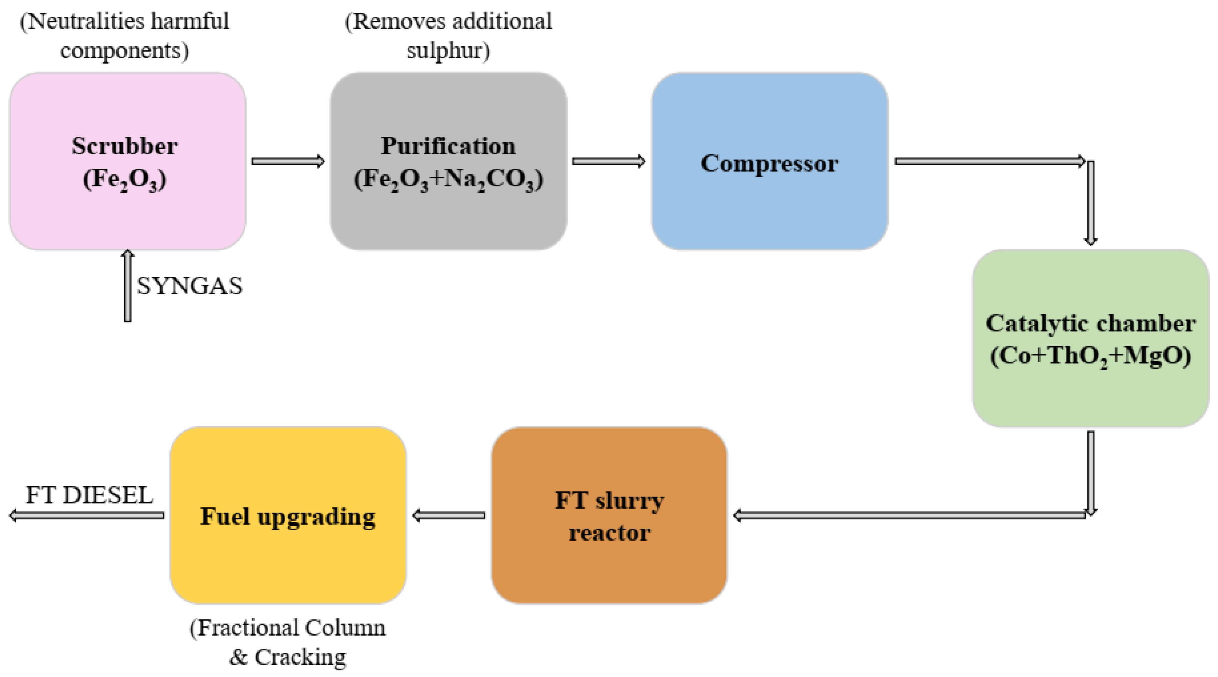
Crude from the FT reactor must undergo refining treatments to maximize desired product yields. Fractional distillation is a crucial process, exploiting the different boiling temperatures of crude components to separate them. This allows the extraction of typical crude-derived products at different heights, including diesel (C12–C22), kerosene (C8–C16), and gasoline (C4–C12) [13].
Figure 8 illustrates the FT process for e-diesel production considering syngas input. The efficiency factor for e-diesel production through this process ranges from 0.82 to 0.83, which is lower than other e-fuel production processes [168]. The sustainability of the process, as with most e-fuels, depends on the source of raw materials [154,169].
Table 2 provides mass and energy balances for the RWGS [170] and FT synthesis [171] for e-diesel production.
At the moment, e-diesel is probably one of the most promising and sustainable e-fuels considering its logistics, refueling network, and onboard use; it could be used in existing ICEs with refueling at gas stations simply as a substitute or additive to current fossil diesel, with its chemical properties being very similar to those of mineral diesel fuels [172,173]. It is noteworthy, in fact, that e-diesel is more like fossil diesel than biodiesel, which is not a hydrocarbon but an ester [13]. In addition, unlike conventional diesel, e-diesel is intrinsically sulfur-free, so it may be classified as a “drop-in” fuel (capable of replacing crude oil-derived products without any change in existing applications) [174]. As of 2022, Finnish company Neste, Indian company Carbon Clean Solutions in collaboration with Lanza Tech, and Audi are among the key players in synthetic diesel production, investing significantly in its further development [13].
E-kerosene is also a synthetic fuel produced through the FT process. To enhance the product’s quality, a hydrocracking plant is used after the FT process to break the long hydrocarbon chains and aid in the formation of hydrocarbons in the middle distillate range, where kerosene resides [175]. E-kerosene is considered an SAF, as it can be produced using RES [176,177,178,179]. Its main application is aircraft fueling. This fuel is typically blended with other kerosene-based fuels such as Jet A, Jet A-1, JP-5, and JP-8 [180,181]. Figure 9 depicts the production cycle and its usage.
E-kerosene is currently used in various countries worldwide, including the United States and Germany [178]. Key players in the e-kerosene sector include SkyNRG, Neste, and LanzaTech. These companies are working to develop and market e-kerosene as a sustainable and clean alternative to traditional aircraft fuel. In addition to these companies, other airlines are exploring the use of e-kerosene to reduce their environmental impact. For example, Lufthansa has successfully conducted numerous test flights using e-kerosene and has announced its intention to regularly use this fuel [182]. Other airlines, such as KLM and United Airlines, are also exploring the use of e-kerosene as a potential alternative to traditional aircraft fuel. However, the production quantity of SAF is still negligible compared to conventional aviation fuel production volumes, as the commercial-scale production of this fuel faces challenges such as compositional complexity and the variability of raw materials [183]. Nevertheless, its adoption is likely to increase as more companies and countries seek to transition to a cleaner and more sustainable energy system. As of 2021, Germany is a key player in e-kerosene production and is looking to further expand its usage [13]. Like e-diesel, e-kerosene can be used without substantial modifications to current engines. Additionally, transport and storage are not particularly problematic (existing infrastructure can be used for these purposes).

3.5. E-Ammonia

Ammonia (NH3) is a chemical compound that has recently garnered attention as an alternative fuel and as hydrogen’s energy carrier [184]. Approximately 80% of its annual production is dedicated to the agricultural fertilizer industry, but it is also used as a raw material for the synthesis of various chemical substances such as plastics, synthetic fibers, resins, refrigerants, and explosives [185,186].
Figure 10 illustrates a schematic of the different pathways for ammonia production. The majority (around 98%) is produced from fossil fuels (natural gas, naphtha, and coal), classified as “brown”, contributing to about 1.8% of global CO2 emissions [17,187]. The conventional method to produce ammonia is the Haber–Bosch (HB) process, described by the reaction [188]:
N 2 + 3 H 2 2 N H 3
Hydrogen reacts with nitrogen at temperatures of 400–450 °C and pressures of 150–200 bar, using an iron-based catalyst. The optimal ratio of hydrogen to nitrogen used in the process is 2:1 to 3:1, with a conversion of approximately 25–35% at each step [189,190]. Ammonia is separated from the gas stream and recycled back into the reactor through cooling at −25 °C, causing its liquefaction. Ammonia produced from fossil fuels with the integration of CCUS techniques and blue hydrogen is termed blue ammonia, while green ammonia is produced solely using RES and green hydrogen resulting in e-ammonia, or through renewable syngas [14].
Ammonia is the simplest nitrogen hydride, with a significantly lower specific energy compared to most hydrocarbon-based fuels. From an environmental perspective, losses of ammonia into soil, air, and water can lead to biodiversity loss, eutrophication, air pollution, GHG emissions, and stratospheric ozone depletion. Burning ammonia releases a great quantity of NOx. These risks must be considered to effectively minimize the hazards of its use [191,192].
Ammonia can also be used as a fuel [193,194,195]. It can power gas turbines, industrial furnaces, or ICEs after partial or complete thermal cracking (a process occurring at temperatures between 400 and 600 °C and pressures between 30 and 100 atm to balance its high ignition temperature) [196]. It could also be burned in engines with a combustion promoter like diesel or hydrogen, which can be obtained directly through the onboard reforming of a small portion of the ammonia itself [197,198]. It has great potential as a hydrogen transport vector, but complete dehydrogenation (chemical and physical separation of the species to produce extremely pure hydrogen) is currently associated with significant losses [199,200]. The Commonwealth Scientific and Industrial Research Organization (CSIRO) of Australia has tested the direct use of ammonia in FCs in two specially built cars. The CSIRO approach involves using a membrane technology incorporated into a modular unit that can be installed at fueling stations for FC vehicles. The membrane is designed to allow smaller hydrogen molecules to pass through while blocking larger nitrogen molecules [201]. The direct use of ammonia in alkaline FCs is also possible and commercialized.
Ammonia is easily stored as a liquid at around 1 MPa, a very low pressure that does not require special high-pressure tanks [202]. The infrastructure necessary for widespread use as a fuel is still under development, but there are projects supported by experts like Wartsila (specializing in engine-related solutions for various sectors). It is considered a potential energy carrier, capable of transporting and storing hydrogen due to its desirable characteristics, such as the ability to be liquified under moderate conditions and its high hydrogen content [91]. According to a study by Bartles, the production cost of ammonia is slightly higher than that of hydrogen, but the latter is characterized by significantly higher transportation and storage costs, making ammonia preferable for energy storage [203]. As of 2022, the major players in global ammonia production include CF Industries Holdings Inc., Yara, Nutrien Ltd., OCI Nitrogen, and OSTCHEM [13]. The Abu Dhabi National Oil Company (ADNOC) recently announced plans to launch a large-scale blue ammonia production plant in Ruwais, United Arab Emirates, with a capacity of 1000 kilotons per year [204].

4. Technological and Environmental Analysis

4.1. Readiness Level Indicators

The Technology Readiness Level (TRL) provides a measure of the maturity of a specific technology, rated on a scale from 1 (basic principles observed) to 9 (actual system proven in operational environments). The use of the TRL allows for consistent and uniform discussions of technical maturity among different types of technologies [205]. Additionally, market readiness level (MRL) and commercial Readiness level (CRL) evaluate market and commercial maturity, rated from 1 to 6. Table 3 introduces the TRL according to [205], the MRL according to [206], and the associated CRL [147] while Figure 11 shows the overlap between TRL and CRL.
The pathways analyzed in this study exhibit varying TRLs. High technological readiness is essential for market entry, represented by MRL, while CRL provides further differentiation based on economic performance in the market. Table 4 summarizes these indicators for different alternative fuel routes.
These pathways are categorized based on the fuel produced: e-hydrogen (e-H2), CO2 capture, e-methane (e-CH4), e-methanol (e-CH3OH) and PtL, which includes the production of liquid fuels from methanol or through the FT process. CO2 capture is not a fuel production pathway but is crucial for e-fuel synthesis. According to the results of the European Joint Research Center (JRC) [147], the level of technological maturity of various e-fuel synthesis options varies between 6 and 9.
Despite technological maturity, many analyzed technologies are not yet commercially viable. For instance, high-temperature electrolysis methanol production has a TRL of 9 but a CRL of 2, indicating that commercial uptake depends on market structure, investment, legislation, and incentives.
Recent studies show improvements in hydrogen production and CO2 capture technologies and an increase in the TRL of e-fuel production technologies. Ref. [134] analyzes what the future trend of the TRL of these technologies should be for the identified research needs, in relation to the GHG neutrality goal and the compliance of air quality goals. The results show that the TRL of these technologies is progressively increasing: a TRL of 7 and 6 is indicated for PEM and SOEC hydrogen production, respectively; still low values (between 4 and 6) for CO2 capture directly from air; and a value of 8 for e-fuels produced via RWGS and FT process. For the future, significantly higher TRL values are called for to meet the climate requirements imposed by the European Commission (TRL values of 8–9).
As for ammonia production and storage, both are fully commercial (currently as a TRL of 8), with an annual market size of more than 150 million tons worldwide [207]. This production comes from fossil raw materials, and its end use is mainly fertilizer production. In contrast, ammonia shows promise as a fuel for next-generation fuel cells due to its high energy density and carbon-free emissions. However, its commercialization faces several challenges. Firstly, ammonia requires high temperatures (500–700 °C) for decomposition into nitrogen and hydrogen, which are essential for fuel cell operation, which complicates system design. Secondly, ammonia is toxic and corrosive, posing risks in handling and storage that must be carefully managed. Lastly, current catalysts used in ammonia fuel cells are prone to degradation and poisoning, reducing their efficiency and lifespan [208,209]. Despite these challenges, ongoing research is making progress in overcoming these barriers, bringing ammonia closer to viability in fuel cell applications [210].

4.2. Conversion Efficiency

As already emphasized, e-fuels are not a primary energy source, but rather a secondary energy carrier. Their production and use involve a series of conversion losses. E-fuels typically compete with direct electrification paths for similar final applications, which usually involve fewer transformations and are potentially more energy-efficient.
Figure 12 illustrates the individual conversion steps and combined efficiencies of various possible applications [211]: low- and high-temperature heat generation and use in light-duty vehicles. Technologies using e-fuels as an energy carrier are compared with corresponding “full electric” counterparts. In both scenarios, electricity is assumed to be produced from the same energy sources (nominally RES). Additional losses from energy transport and storage, such as those from hydrogen liquefaction, regasification, transport, and distribution, are excluded from this efficiency analysis [211].
Depending on the application and the respective technologies, the overall efficiency of e-fuels, defined as the conversion of electricity to useful energy, ranges from approximately 10% to 35%. This necessitates power generation requirements that are 2 to 14 times higher than direct electrification alternatives. For e-fuel production, exact efficiency values vary depending on the specific types of electrolysis, synthesis, and fuel type. Producing hydrocarbon from electricity currently requires at least two conversion steps (electrolysis and hydrocarbon synthesis), with electricity-to-fuel efficiency losses amounting to about 60%. This figure also includes the electricity requirement of approximately 6% of the total electricity input when capturing CO2 from DAC [212]. It is optimistically assumed that the heat demand of DAC, which comprises about 15–20% of the total energy input, is met by waste heat from other processes and is therefore excluded from the calculation (this assumption holds true only if the carbon capture plant is located near the e-fuel synthesis plant) [213].
Approximately 70% of the remaining energy content of e-fuel is lost when it is used for mechanical work (in transportation engines or gas turbines), resulting in electricity-to-useful-energy efficiency for transportation of about 10%. Using e-fuels in an ICE of a passenger car thus requires about five times more (renewable) electricity than the direct use of electricity in an equivalent BEV, where the conversion chains are shorter and retain most of the electrical energy (not dependent on combustion). When e-fuels are used for low-temperature heating (<100 °C) in buildings and industry, the efficiency disadvantage is primarily due to losses during e-fuels production (current gas boilers are highly efficient). Consequently, the efficiency of e-fuels is about half that of the corresponding direct electricity use technology (heat pumps). For high-temperature (>100 °C) heat supply in industrial applications, the efficiency depends on gas boilers and furnaces, which have efficiencies ranging from about 50 to 90% (depending on temperature and industrial process). Heat pumps, on the other hand, can make very efficient direct use of electricity, achieving a coefficient of performance (COP; ratio of heat output to electricity input) of more than 2. This results in energy efficiencies that are 6–14 times higher than using e-fuels [214].

4.3. Climate Mitigation Effectiveness

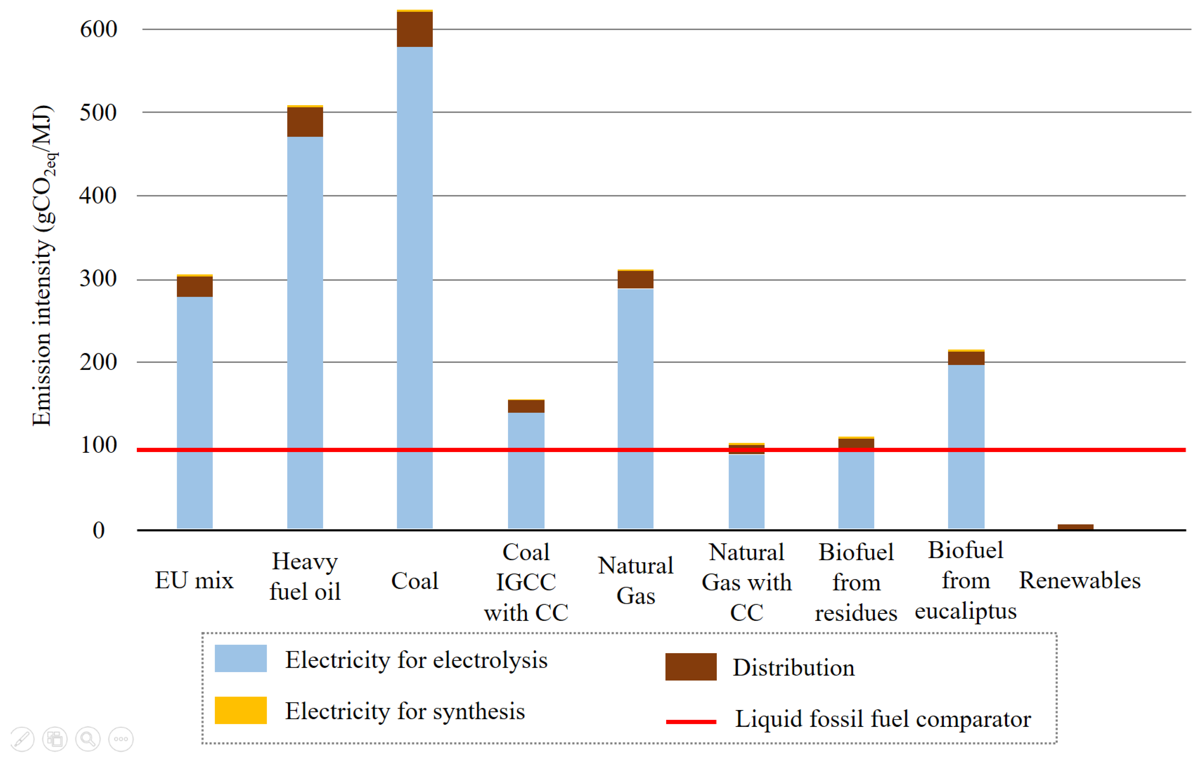
Figure 13 presents the results of the Life Cycle Assessment (LCA) for producing e-diesel from methanol. This analysis evaluates the lifecycle carbon intensity based on energy consumption and electricity carbon intensities [104].
As previously discussed, the GHG emissions associated with e-fuel production are predominantly influenced by the GHG intensity of the electricity used in electrolysis and, to a lesser extent, fuel synthesis. E-fuels, being structurally similar to conventional fuels, do not require changes in storage and distribution logistics, resulting in minimal emissions from these processes. The primary mechanism to ensure low GHG intensity for e-fuels is the utilization of additional renewable capacity for electricity consumption. When zero-carbon renewables (e.g., wind, photovoltaic, concentrated solar) are used, e-fuels exhibit very low GHG emission intensity. According to the JRC study, the lifecycle carbon intensity for the e-diesel pathway via methanol is calculated at 1.3 g(CO2eq)/MJ [215]. This value represents a 99% reduction compared to the carbon intensity of fossil diesel consumed in the European Union (94 g(CO2eq)/MJ [216]). This analysis assumes the exclusive use of renewable electricity for all energy conversion processes and the utilization of thermal energy from fuel synthesis in heat-requiring processes.
E-diesel produced using electricity from coal combustion, based on JRC data and efficiency assumptions (with an overall process requirement of 2.45 MJ of electricity per 1 MJ of fuel), exhibits a carbon intensity nearing 600 g(CO2eq)/MJ, which is six times worse than fossil diesel. Using the European energy mix, the GHG intensity would be 307 g(CO2eq)/MJ, three times that of fossil fuels. As depicted in Figure 13, e-diesel shows higher carbon intensity than fossil diesel in all scenarios except for zero-carbon renewables. Even e-fuels produced from biomass may have similar or higher GHG intensities compared to their fossil counterparts (GHG intensity of biomass electricity from [216], other electricity GHG intensities from [215]). Therefore, it is crucial for the environmental performance of e-fuels that the electricity supply comes exclusively from low-carbon renewable sources. Emissions from plant construction are not typically included in the lifecycle but are relatively small over the plant’s operational lifespan. Other studies report similarly low lifecycle emissions for e-fuels, noting that emissions from constructing renewable energy facilities, often excluded from lifecycle analyses, can be significant. An additional 10 g(CO2eq)/MJ for wind power development and 27 g(CO2eq)/MJ for photovoltaic capacity development should be considered [217]. In conclusion, e-fuels have the potential to be low-emission alternatives to fossil fuels, but their climate mitigation effectiveness is critically dependent on the carbon intensity of the electricity and the CO2 source.
Figure 14 examines various applications in the transportation sector: light-duty vehicles (easy to abate), heavy-duty trucks (difficult to abate), and long-distance aviation (difficult to abate and not feasible for electrification).
GHG emissions for these transportation modes, obtained from a comprehensive life cycle assessment [15], are shown as a function of the lifecycle carbon intensity of electricity used for battery charging, hydrogen production, and e-fuel synthesis, as well as for two different CO2 sources (DAC and CCUS). The slope of the lines depends on the electricity required for each conversion pathway. The lines are horizontal for reference fossil technologies (negligible electrical input) and steeper for e-fuel vehicles, due to their low overall energy efficiencies and thus high electrical input. Residual emissions with a 100% renewable electricity share are mainly determined by the embedded lifecycle energy requirements for constructing and producing wind and photovoltaic systems for vehicles or batteries.
These baseline emissions could approach near-zero levels in the long term if the industrial sector can be transformed into a zero-emission sector. Results show that in all the considered applications, a 90–100% share of renewable electricity is required to reduce GHG emissions compared to fossil alternatives using e-fuels. With Germany’s 2018 electricity mix (carbon intensity of 542 g(CO2eq)/kWh [220]), the use of e-fuels in cars, trucks, or planes would produce three to four times more GHG emissions than the use of fossil fuels. The direct use of hydrogen (for light vehicles or trucks) is slightly better. Thus, as seen in the previous LCA analysis, only for power systems truly based on renewable sources do electronic fuels or hydrogen become an effective mitigation option. This suggests that for most countries and energy systems, no mitigation contribution can be expected from e-fuels or hydrogen before 2030, unless they are imported from countries that build the necessary additional renewable capacity, electrolyzers, DAC plants, CO2 storage, and transport infrastructure.
Battery electric alternatives for light-duty vehicles, on the other hand, have GHG emissions already comparable to or lower than those of diesel, gasoline, or natural gas vehicles with current electricity mixes for many countries [221]. The performance of BEVs depends heavily on advances in battery technology, particularly their energy density. Both battery-electric trucks with a range of 150 km (primarily for inner-city transport with potential charging interruptions) and long-distance trucks with a range of 800 km (requiring larger batteries and reducing maximum payload) reduce GHG emissions per ton-km with renewable electricity shares above 60–65%. For long-distance aviation, there is no direct electric or hydrogen option. E-kerosene can reduce GHG emissions by about one-third with 100% renewable electricity. Aviation remains a challenging sector for decarbonization, where even e-fuels can only partially mitigate emissions.
A direct comparison between BEVs and vehicles powered by e-fuels (both ICE and FC) was conducted, considering 15 kWh/100 km of energy consumed (energy to wheels) for a medium-sized passenger car in the Worldwide Harmonized Vehicles Test Procedure (WLTP) [32]. The analysis is based on the average well-to-tank (WTT) and tank-to-wheel (TTW) efficiencies, leading to the well-to-wheel (WTW) efficiency and the specific power consumption (in kWh/100 km). All values are shown in Table 5.
Considering the fuel consumption of the current ICE is approximately 65.6 kWh per 100 km [222,223], a TTW efficiency of 0.35 is selected, assuming future ICE engines will utilize more efficient powertrains. For FC vehicles, an efficiency of 0.5 is chosen, reflecting the conversion efficiency of onboard e-fuel energy into vehicle propulsion. BEVs are assigned an overall WTW efficiency of 0.77 [224], considering the current technology state of electric drive and storage systems, with an average TTW efficiency of 0.90. Only lithium battery storage systems are considered for BEVs.
When normalizing specific electricity consumption against BEVs (Figure 15), it is clear that e-fuels require three to five times more electricity to achieve the same purpose, which is consistent with the earlier results. This significant efficiency gap is a critical distinction between electricity and e-fuels. On a large scale, such as national or global road transport, the high electricity demand could present an insurmountable barrier. Analysis within the light transport sector demonstrates that e-fuels are not competitive with existing alternatives. Given the substantial amount of renewable electricity required for their use, these fuels are most suitable for sectors lacking viable electric alternatives, such as heavy transport or aviation. Additionally, energy efficiency impacts the total cost of vehicles: lower efficiency results in higher operating costs. Furthermore, lower efficiency implies higher equivalent emissions, especially considering the residual CO2 emission factor of grid electricity.
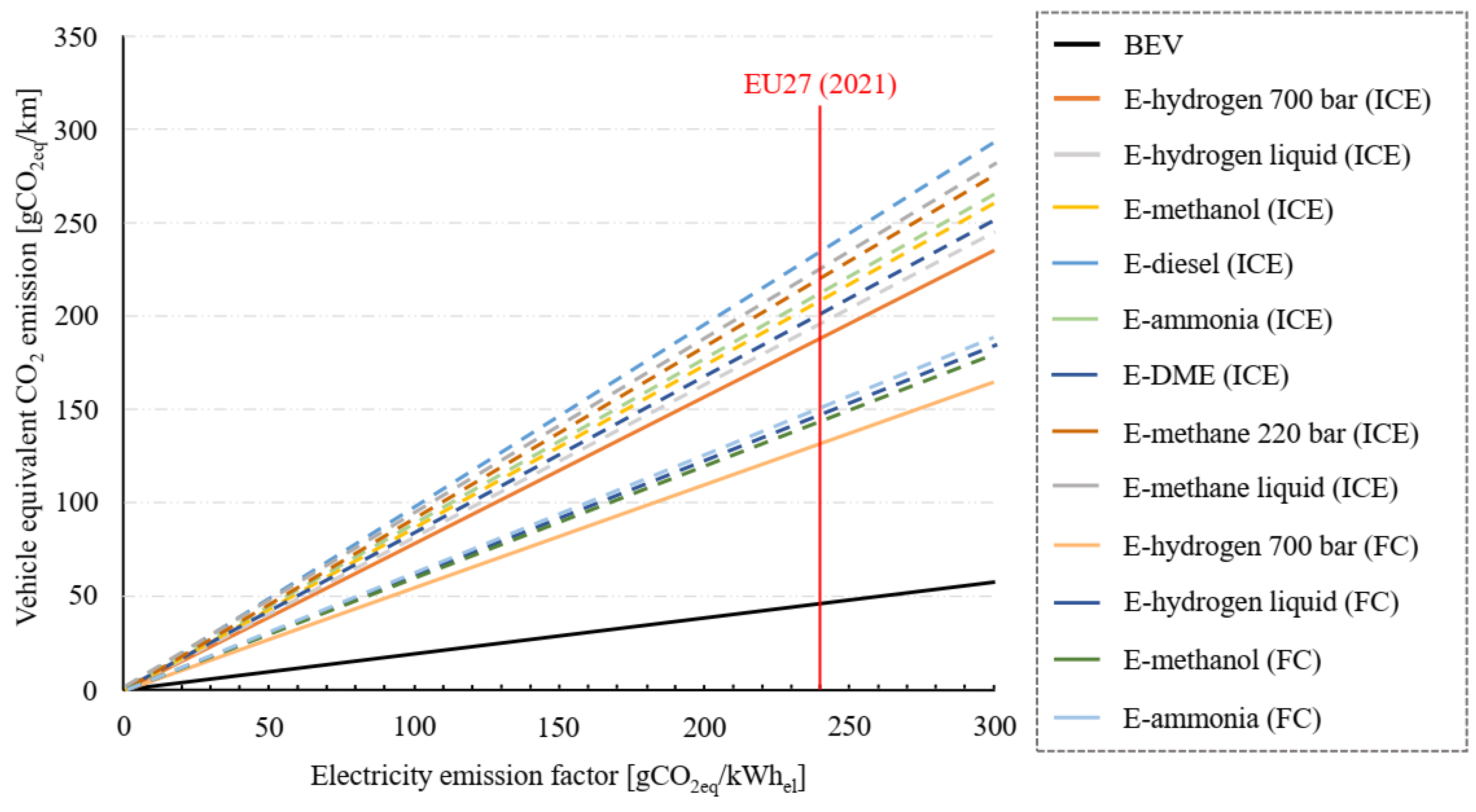
Figure 16 depicts the equivalent vehicle emissions (in g(CO2)/km) based on the electric power emission factor [32]. Solid lines represent market-ready technologies, while dashed lines indicate less mature technologies.
Electricity used in BEVs consistently results in the lowest CO2 emissions. E-fuels, however, could generate higher emissions than current fossil fuels if the electricity generation sector is not sufficiently decarbonized. The emission intensity from electricity production in the European Union has decreased to 241 g(CO2)/kWhel as of 2021. With this current emission factor, electric cars emit less than 50 g(CO2)/km, whereas e-fuels range from 140 to 240 g(CO2)/km, higher than emissions from current fossil-fueled ICEs. These values align with previous analyses presented.

5. E-Fuel Challenges and Perspectives

The necessity to transform the global energy system to address contemporary challenges is paramount for preserving planetary health and ensuring human livelihoods. The initial phase of this energy transition should involve the gradual phasing out of fossil fuels. Despite the progress reported by the scientific community, several critical issues remain to be addressed in current energy systems to facilitate a sustainable transition towards e-fuels.
Regarding the exhaustibility of primary sources for energy production, fossil fuels are derived from underground reserves that take millions of years to form. In contrast, e-fuels, assuming the exclusive use of renewable energies, have an indefinite availability as long as there is water for hydrogen production and CO2 for fuel synthesis [20]. While water consumption details are unclear, the CO2 supply is expected to see an increase in CCUS techniques initially and, with the decline of fossil fuels, a rise in DAC technology [19].
Concerning energy dependency among countries, fossil fuels are naturally confined to specific geographic locations. In contrast, e-fuel production does not necessitate special geographical conditions, leading to a potential shift rather than a collapse in the energy market. This shift is primarily due to the renewable energy demand for e-fuel production processes, which depend on geographic features like abundant sunlight, significant water flows, or consistent wind patterns. Some regions may be more favorable for renewable exploitation, while others might face logistical challenges in e-fuel production [20,225].
Addressing pollution and GHG emissions, hydrocarbon combustion—whether from fossil fuels or e-fuels—produces primary pollutants. The key distinction is that e-fuels do not emit sulfur oxides (SOx) due to the absence of sulfur in their composition, unlike fossil fuels, which contain sulfur from geological sources. Consequently, while e-fuels reduce local pollution issues, they do not entirely eliminate them [226]. The complete combustion of e-fuels also produces CO2. However, the emitted CO2 is approximately equal to the CO2 extracted from the atmosphere or point sources for e-fuel production, assuming renewable energy is used throughout the process. This balance implies that e-fuels do not contribute additional GHG emissions [15,32,104]. Discussing pollution necessitates addressing the environmental consequences associated with the disposal of renewable energy infrastructure, such as wind turbines and solar panels, which supply the necessary energy for e-fuel production [227]. While these technologies provide significant reductions in greenhouse gas emissions during their operational life, their end-of-life phase can pose environmental challenges. The proper disposal and recycling of these facilities are critical to minimizing their overall environmental footprint and ensuring that the transition to renewable energy remains sustainable [228]. These considerations provide a broad perspective on an energy system where e-fuels replace fossil fuels. An energy system comprises primary sources, energy carriers, and utilization technologies. Altering one component necessitates adjustments in the others. To better understand the implications of integrating e-fuels into the energy system, further observations are warranted.
The primary sources for e-fuel production—water, CO2, and renewable energy—differ significantly from fossil sources. However, the end products, e-fuels, are liquid or gaseous fuels that closely resemble conventional fuels in composition and properties [32,147] (see Table 6 and Table 7).
This similarity is a significant advantage of e-fuels, as it negates the need to change the energy carrier. The transport and storage systems for e-fuels can utilize the existing infrastructure designed for fossil fuels. Furthermore, the final utilization technologies do not require substantial modifications, as e-fuels have properties similar to conventional fuels, making them suitable for current distribution networks as drop-in fuels [16]. This compatibility means no investment is needed for retrofitting transport systems or usage technologies. This is not the case for e-hydrogen, e-ammonia, and e-DME/OME, as hydrogen presents challenges in transportation and storage due to its low volumetric density, and while the direct combustion of hydrogen has been extensively researched, it is not yet a marketable technology. Ammonia, DME, and OME are not currently used as fuels, necessitating new systems for their transport, storage, and changes to utilization technologies [16,27]. Table 8 provides a qualitative overview of storability, infrastructure, and powertrain development.
If a transition of the energy system to 100% electricity is considered, significant changes would be necessary in both energy logistics and utilization technologies. These changes would include modifying the electricity transmission and distribution network to be bi-directional rather than one-way, as well as the replacement of technologies (e.g., natural gas boilers with heat pumps for heat generation and ICEs and turbomachines with electric motors for mobility) [32,230]. Notably, these transformations would demand increased exploitation of materials like rare earths, nickel, copper, and cobalt, inevitably leading to new dependencies between countries for material imports and exports and issues related to the recycling of these materials [231]. The transition from fossil sources, along with the adaptation of transport and storage infrastructure and the replacement of end-use technologies, entails substantial investment costs for the implementation and commercialization of these technologies [104].
In terms of reducing GHG, electricity, biofuels, and e-fuels all have considerable potential. For e-fuels, an 85% reduction in the mobility sector’s GHG emissions is estimated, assuming renewable energy is used for all production processes. The primary obstacle to realizing this potential is the significant renewable energy demand, especially for the electrolysis process in e-fuel production. To supply 50% of all transport energy via e-fuels, approximately 2720 TWh of additional renewable electricity would be required, which is 75% of the current total electricity production in Europe. Considering e-fuels’ use in the most challenging sectors to electrify, two scenarios are examined. Meeting 50% of European aviation energy demand in 2050 with e-fuels would require 880 TWh of additional renewable electricity, about 24% of the current European supply. Similarly, supplying 50% of truck energy would necessitate 1310 TWh of renewable electricity or 36% of the current European electricity supply [104]. The decarbonization scenarios outlined in the 2050 roadmap already imply significant ambition and investment to provide the additional renewable electricity capacity needed for household and industry decarbonization and a growing fleet of electric vehicles. Therefore, the large capacity additions required to meet a substantial portion of the transport energy supply would be extremely challenging to achieve.
Table 9 presents key parameters of e-fuels compared to alternative options.
Another issue with an energy system based solely on renewable electricity is the variability in power generation, which leads to periods when no power is generated or when demand exceeds production, as well as periods of excess power generation without corresponding demand. This variability necessitates long-term energy storage, which is challenging with current battery technologies. E-fuels could serve as a means of storing electrical energy in chemical bonds (Figure 17). The concept involves producing e-fuels during periods of surplus energy and using them when needed. However, this is a long-term consideration, as the current surplus of renewable energy is insufficient for large-scale e-fuel production [108].
Next, we assess the sectors where e-fuels are most likely to contribute positively to decarbonization. Table 10 provide an overview of the potential use of e-fuels in various sectors.
In the aviation sector, e-kerosene stands out due to its high energy density and compatibility with existing infrastructure and aircraft engines. Research indicates that e-kerosene could significantly reduce GHG emissions compared to conventional jet fuels, potentially saving about 5 Mt of CO2 with the use of approximately 2 million tonnes of e-kerosene by 2030 [232]. This technology enables the aviation industry to uphold operational standards while substantially reducing its carbon footprint, making it an attractive option for this challenging sector. For maritime uses, e-ammonia, e-methanol, and e-diesel are noted for their low emissions and established applications in shipping [14,233]. E-ammonia is particularly noted for its potential to cut CO2 emissions when produced via green hydrogen, offering a viable solution for sustainable long-distance and heavy-load maritime transport with moderate infrastructural changes [234]. In heavy-duty transport, e-diesel presents a strong case [235,236,237]. E-diesel can be seamlessly integrated into existing diesel engines and infrastructure, achieving up to an 85% reduction in GHG emissions when derived from renewable sources [27]. This renders e-diesel an effective choice for sectors such as freight and logistics, which predominantly rely on diesel engines. In light-duty vehicles, transitioning to e-fuels is generally less favorable compared to direct electrification due to the lower efficiency and higher costs associated with e-fuel production and conversion. Nonetheless, in areas where electrification progress is slow or impractical, e-fuels can significantly reduce emissions, offering about a 60% decrease in GHG emissions relative to conventional gasoline [27]. Additionally, considering the gradual nature of the industry’s shift to full electrification, using e-fuels to reduce CO2 emissions in the interim is a viable strategy. Overall, e-fuels offer a substantial opportunity to lessen GHG emissions across various transportation sectors. However, their implementation largely depends on the availability of renewable energy sources and technological advancements in production [234,235]. The selection of an e-fuel for each scenario should consider specific energy requirements, existing infrastructure, and regional energy policies to ensure optimal integration and sustainability outcomes.
The inherent problem with e-fuels is the inefficiency of thermodynamic conversion. From electricity to e-fuel, there is about a 40% loss. This inefficiency means technologies that use electricity directly will generally be preferred. For instance, heat pumps, which have high efficiencies and use electricity directly, have much lower energy losses for generating low-temperature heat compared to e-fuels. Although boilers are efficient, producing e-fuels involves significant energy losses at various transformation stages. This efficiency gap is smaller for high-temperature heat generation applications, where electrical technologies are less efficient but still outperform e-fuels overall [32].
In the mobility sector, similar conclusions apply, but additional considerations are necessary. For sectors like heavy transport, shipping, and aviation, which lack electric alternatives in the short term, fully electric trucks, ships, or planes remain a distant possibility despite ongoing research [237,238,239,240]. To help decarbonize these sectors, e-fuels present a viable solution. However, other technologies like biofuels, FCEV, or direct hydrogen use are also being explored. A diversified approach to achieving net-zero emissions can be beneficial. For light transport, BEVs offer a more efficient alternative to combustion engines using e-fuels [15]. However, the large-scale adoption of electric vehicles requires retrofitting the electrical system, transport, and storage logistics and replacing existing vehicles. This takes quite a long time, dictated not only by the maturity of the technologies but also by the market’s willingness to innovate. In the short term, introducing e-fuels could accelerate emission reductions in this sector.
An analysis of the TRL, MRL, and CRL indices for e-fuel production technologies reveals that many are not yet commercially viable or mature enough for market entry. Interestingly, despite sufficiently high technological maturity, their commercial availability is still limited. For instance, e-methanol production through high-temperature electrolysis has a TRL of 9, while its CRL is 2 (see Table 4) [147]. This indicates that commercial deployment depends on factors beyond technological maturity, such as market structure, investment in new plants, supporting legislation, and financial incentives. In this context, direct electrification is more incentivized, leading to quicker market adoption. It is also crucial to highlight the current absence of comprehensive industrial standards governing the transportation, storage, and usage of e-fuels. This gap poses significant challenges as it can hinder the effective integration of these fuels into existing energy systems. Developing and implementing robust standards is essential to ensure safety, efficiency, and environmental compliance across all stages of e-fuel handling, from production to end-use.
Currently, the capital cost of implementing new technologies makes e-fuels significantly more expensive than fossil fuels or electric alternatives, reducing their attractiveness to consumers and producers. However, plans are underway to implement subsidies, including incentives for developing and using synthetic fuels, research and development funding, tax incentives, and subsidies for pilot projects to reduce production costs. Hydrogen, in particular, receives substantial subsidies due to its potential role in the low-carbon energy transition [241,242].
The cost of e-fuels mainly hinges on electricity costs. At present electricity prices, e-fuels are not competitive. Additionally, local technical and economic analyses are necessary for each geographic area to determine the most suitable synthesis process and energy strategy. CO2 supply technologies, especially DAC, are also expensive. Currently, e-fuels can cost up to EUR 7 per liter, but prices are expected to fall due to economies of scale and declining renewable electricity prices, potentially reaching EUR 1 to EUR 3 per liter by 2050 (excluding taxes). Although the levelized cost of fuel (LCOF) is high in early transition periods, it is projected to decrease significantly by 2050 [20].
Forecasting the trade of e-fuels, their large-scale market entry, and their actual impact on pollution and GHG emissions is complex. As an immature and less commercial technology, such analyses must rely on assumptions about future renewable electricity capacity, improvements in hydrogen production electrolyzers, CO2 capture capabilities from point sources or the air, maturity of e-fuel production technologies, and associated costs.

6. Conclusions

The transition of the global energy system from the current fossil-fuel-based framework to a 100% renewable energy system is critical for reducing GHG emissions and meeting the Paris Agreement’s goal of limiting global warming to below 1.5 °C compared to pre-industrial levels. The increasing share of renewable energy generation presents an opportunity to develop new technologies, such as e-fuels, which have garnered significant interest in recent years. Hydrogen production through electrolysis forms the basis for e-fuel production, and the development of electrolysis technologies is ongoing. The most mature technologies are AEC and PEM, while newer technologies like SOEC are emerging. The hydrogen produced, besides being suitable as a fuel, can be combined with CO2 to create fuels similar to conventional ones. The climate benefits of these fuels over fossil fuels depend primarily on the electricity used in their production; if only renewable electricity is used, they can reduce emissions by more than 80% compared to fossil fuels.
As a result of this review, the potential for e-fuels appears to be greatest in the maritime and aviation sectors, while BEVs are becoming the dominant type in road transport. However, markets for e-fuels in road transport will persist in the upcoming years, as replacing ICE vehicles with electric ones is a gradual process. Regarding the supply of carbon sources, CCUS technologies could predominate at the beginning but to meet the entire fuel demand, DAC definitely needs to be integrates. The cost of e-fuels must be at least comparable to that of fossil fuels for widespread adoption, so policy actions and financial incentives need to be implemented. Given the high demand for renewable energy for all processes involved, the possibility of meeting its production in specific regions more suitable for the exploitation of renewable resources should be considered. The blending with fossil fuels is possible (the blending with biofuels should be investigated), so there is the possibility to increasingly replace the amount of e-fuels in fossil fuels, giving time for new renewable power plants and all the logistics in the electrical system to be improved.
In conclusion, considering infrastructure, safety, transportation, and supply, and with the anticipated reduction in the cost of renewable electricity, electrolyzers, and CO2 capture, the production of e-fuels is promising. They can serve as excellent energy carriers, means of electricity storage, and fuels for various applications, as well as raw materials for the chemical industry (e.g., e-methane, e-methanol, and e-ammonia). Addressing all the barriers and limitations through further research is crucial for the successful implementation of the technology and for meeting the challenge of decarbonizing the global economy.

Author Contributions

Conceptualization, C.V., G.V. and K.G.; validation, C.V., K.G., G.V. and A.D.G.; formal analysis, C.V., S.D. and G.V.; investigation, S.D., C.V. and G.V.; data curation, C.V., S.D. and G.V.; writing—original draft preparation, S.D.; writing—review and editing, S.D., C.V., K.G., G.V. and A.D.G.; visualization, S.D.; supervision, C.V., K.G., G.V. and A.D.G.; project administration, C.V., K.G., G.V. and A.D.G.; funding acquisition, G.V., K.G. and C.V. All authors have read and agreed to the published version of the manuscript.

Funding

Accordi di programma MiTE—ENEA per la regolamentazione dei rapporti in relazione allo svolgimento di attività di ricerca nell’ambito del Piano Nazionale di Ripresa e Resilienza (PNRR)—Missione 2—Componente 2—Investimento 3.5, finanziato dall’unione europea—Next Generation Eu, Piano di Ricerca “Ricerca e sviluppo di tecnologie per la filiera dell’idrogeno”.

Conflicts of Interest

The authors declare no conflicts of interest.

Abbreviations

The following abbreviations are used in this manuscript:
AECAlkaline electrolyzer cell
BEVBattery electric vehicles
CCSCarbon capture and storage
CCUSCarbon capture utilization and storage
CRLCommercial readiness level
CSIROCommonwealth scientific and industrial research organization
DACDirect air capture
DMEDimethyl ether
FCFuel-Cell
FTFischer–Tropsch synthesis
GHGGreenhouse gas
GtLGas-to-liquid
GWPGlobal warming potential
ICEInternal combustion engine
JRCJoint research centre
LCALife cicle assessment
LHVLower Heating Value
LPGLiquefied Petroleum Gas
MRLMarket readiness level
MTGMethanol-to-Gasoline
OMExOxymethylene ethers
PEMProton exchange membrane
PtFPower-to-fuel
PtGPower-to-gas
PtLPower-to-liquid
PtXPower-to-X
RESRenewable energy sources
RFNBORenewable fuels of non-biological origin
RWGSReverse water gas shift
SAFSustainable Aviation Fuel
SOECSolid oxide electrolyzer cell
TRLTechnology readiness level
TSATemperature swing adsorption
TTWTank-to-Wheel efficiency
WLTPWorldwide harmonized vehicles test procedure
WTTWell-to-Tank efficiency
WTWWell-to-Wheel efficiency

References

  1. Our World in Data. Available online: https://ourworldindata.org/grapher/global-fossil-fuel-consumption (accessed on 12 February 2024).
  2. Energy Institute. Available online: https://www.energyinst.org/statistical-review (accessed on 12 February 2024).
  3. Bp Global. Available online: https://www.bp.com/content/dam/bp/business-sites/en/global/corporate/pdfs/energy-economics/statistical-review/bp-stats-review-2021-full-report.pdf (accessed on 12 February 2024).
  4. Lund, L. Introduction to Chemistry; LibreTexts: Coon Rapids, MN, USA, 2023; pp. 16.1.1–16.14.1. [Google Scholar]
  5. Kovacs, B.; Mathijs, E.; Freibauer, A.; Brunori, G.; Damianova, Z.; Faroult, E.; Girona, J.; OBrien, L.; Treyer, S. Sustainable Food Consumption and Production in a Resource-Constrained World, 3rd ed.; EuroChoices: Leeuwarden, The Netherlands, 2011. [Google Scholar]
  6. Our World in Data. Available online: https://ourworldindata.org/grapher/ghg-emissions-by-gas (accessed on 12 February 2024).
  7. Our World in Data. Available online: https://ourworldindata.org/explorers/climate-change?facet=none&Metric=Temperature+anomaly&Long-run+series=false&country=OWID_WRL~ATA~Gulkana+Glacier~Lemon+Creek+Glacier~OWID_NAM~South+Cascade+Glacier~Wolverine+Glacier~Hawaii~Arctic+Ocean (accessed on 12 February 2024).
  8. GISTEMP Team. GISS Surface Temperature Analysis (GISTEMP), Version 4; NASA Goddard Institute for Space Studies: New York, NY, USA, 2024. Available online: https://data.giss.nasa.gov/gistemp/ (accessed on 12 February 2024).
  9. Newman, R.; Noy, I. The global costs of extreme weather that are attributable to climate change. Nat. Commun. 2023, 14, 6103. [Google Scholar] [CrossRef] [PubMed]
  10. Arshad, M.; Zia, M.; Shah, S.F.; Ahmad, M. An Overview of Biofuel. In Perspectives on Water Usage for Biofuels Production; Arshad, M., Ed.; Springer: Lahore, Pakistan, 2018; pp. 1–37. [Google Scholar]
  11. Das, P.; Gundimeda, H. Is biofuel expansion in developing countries reasonable? A review of empirical evidence of food and land use impacts. J. Clean. Prod. 2022, 372, 133501. [Google Scholar] [CrossRef]
  12. Ruth, C.; Stephanopoulos, G. Synthetic fuels: What are they and where do they come from? Curr. Opin. Biotechnol. 2023, 81, 102919. [Google Scholar] [CrossRef] [PubMed]
  13. Ram, V.; Salkuti, S.R. An Overview of Major Synthetic Fuels. Energies 2023, 16, 2834. [Google Scholar] [CrossRef]
  14. Nemmour, A.; Inayat, A.; Janajreh, I.; Ghenai, C. Green hydrogen-based E-fuels (E-methane, E-methanol, E-ammonia) to support clean energy transition: A literature review. Int. J. Hydrogen Energy 2023, 48, 29011–29033. [Google Scholar] [CrossRef]
  15. Ueckerdt, F.; Bauer, C.; Dirnaichner, A.; Everall, J.; Sacchi, R.; Luderer, G. Potential and risks of hydrogen-based e-fuels in climate change mitigation. Nat. Clim. Chang. 2021, 11, 384–393. [Google Scholar] [CrossRef]
  16. Ababneh, H.; Hameed, B.H. Electrofuels as emerging new green alternative fuel: A review of recent literature. Energy Convers. Manag. 2022, 254, 115213. [Google Scholar] [CrossRef]
  17. Reddy, V.J.; Hariram, N.P.; Maity, R.; Ghazali, M.F.; Kumarasamy, S. Sustainable E-Fuels: Green Hydrogen, Methanol and Ammonia for Carbon-Neutral Transportation. World Electr. Veh. J. 2023, 14, 349. [Google Scholar] [CrossRef]
  18. Bharti, S.; Chauhan, B.V.S.; Garg, A.; Vedrtnam, A.; Shukla, M.K. Potential of E-Fuels for Decarbonization of Transport Sector. In Greener and Scalable E-Fuels for Decarbonization of Transport; Agarwal, A.K., Valera, H., Eds.; Springer: Singapore, 2022; pp. 9–32. [Google Scholar]
  19. Galimova, T.; Ram, M.; Bogdanov, D.; Fasihi, M.; Khalili, S.; Gulagi, A.; Karjunen, H.; Mensah, T.N.O.; Breyer, C. Global demand analysis for carbon dioxide as raw material from key industrial sources and direct air capture to produce renewable electricity-based fuels and chemicals. J. Clean. Prod. 2022, 373, 133920. [Google Scholar] [CrossRef]
  20. Galimova, T.; Ram, M.; Bogdanov, D.; Fasihi, M.; Gulagi, A.; Khalili, S. Global trading of renewable electricity-based fuels and chemicals to enhance the energy transition across all sectors towards sustainability. Renew. Sustain. Energy Rev. 2023, 183, 113420. [Google Scholar] [CrossRef]
  21. Perner, J.; Unteutsch, M.; Lövenich, A. The Future Cost of Electricity-Based Synthetic Fuels. In Agora Verkehrswende, Agora Energiewende and Frontier Economics (2018): The Future Cost of Electricity-Based Synthetic Fuels; Energiewende, A., Verkehrswende, A., Eds.; Frontier Economics: Cologne, Germany; Im Zollhafen: Cologne, Germany, 2018; pp. 7–41. [Google Scholar]
  22. Tsiklios, C.; Schneider, S.; Hermesmann, M.; Müller, T.E. Efficiency and optimal load capacity of E-Fuel-Based energy storage systems. Adv. Appl. Energy 2023, 10, 100140. [Google Scholar] [CrossRef]
  23. Viscardi, R.; Nigliaccio, G.; Bassano, C.; Deiana, P. The potential of E-fuels as future fuels. FOCUS ENEA 2021, 112–116. [Google Scholar]
  24. Palys, M.J.; Daoutidis, P. Power-to-X: A review and perspective. Comput. Chem. Eng. 2022, 165, 107948. [Google Scholar] [CrossRef]
  25. Decourt, B. Weaknesses and drivers for power-to-X diffusion in Europe. Insights from technological innovation system analysis. Int. J. Hydrogen Energy 2019, 44, 17411–17430. [Google Scholar] [CrossRef]
  26. Research Gate. Available online: https://www.researchgate.net/publication/369229902_The_Best_Fuels_For_The_Future (accessed on 12 February 2024).
  27. Yugo, M.; Soler, A. Role of e-Fuels in the European Transport System—Literature Review; Report no. 14/19; Concawe: Brussels, Belgium, 2020. [Google Scholar]
  28. Zlenko, M.; Terenchenko, A. E-fuels—Last hope for internal combustion engine. Tr. NAMI 2023, 81, 15–34. [Google Scholar] [CrossRef]
  29. ICCT. The International Council on Clean Transportation. Available online: https://theicct.org/e-fuels-wont-save-the-internal-combustion-engine/#:~:text=To%20compound%20the%20problem%2C%20according%20to%20various%20studies,energy%20from%20the%20sun%20or%20wind%20is%20lost. (accessed on 12 February 2024).
  30. Transport & Environment. Available online: https://www.transportenvironment.org/discover/e-fuels-in-trucks-expensive-scarce-and-less-green-than-batteries/ (accessed on 12 February 2024).
  31. Krajinska, A. Magic green fuels. Why synthetic fuels in cars will not solve Europe’s pollution problems. Transp. Environ. 2021, 33–39. Available online: https://www.concawe.eu/publication/concawes-response-to-the-publication-and-presentation-of-tes-report-magic-green-fuels-why-synthetic-fuels-in-cars-will-not-solve-europes-pollution-problems/ (accessed on 12 February 2024).
  32. Pasini, G.; Lutzemberger, G.; Ferrari, L. Renewable Electricity for Decarbonisation of Road Transport: Batteries or E-Fuels? Batteries 2023, 9, 135. [Google Scholar] [CrossRef]
  33. Baykara, S.Z. Hydrogen: A brief overview on its sources, production and environmental impact. Int. J. Hydrogen Energy 2018, 43, 10605–10614. [Google Scholar] [CrossRef]
  34. Rameez, P.V.; Mohamed Ibrahim, M. A comprehensive review on the utilization of hydrogen in low temperature combustion strategies: Combustion, performance and emission attributes. J. Energy Inst. 2024, 113, 101511. [Google Scholar] [CrossRef]
  35. Bonah Agyekum, E.; Odoi-Yorke, F.; Abeley Abbey, A.; Kafui Ayetor, G. A review of the trends, evolution, and future research prospects of hydrogen fuel cells—A focus on vehicles. Int. J. Hydrogen Energy 2024, 72, 918–939. [Google Scholar] [CrossRef]
  36. Taskin, J.; Shafiullah, G.M.; Dawood, F.; Kaur, A.; Arif, M.T.; Pugazhendhi, R.; Elavarasan, R.M.; Forruque, S.A. Fuelling the future: An in-depth review of recent trends, challenges and opportunities of hydrogen fuel cell for a sustainable hydrogen economy. Energy Rep. 2023, 10, 2103–2127. [Google Scholar]
  37. Lixin, F.; Zhengkai, T.; Siew, H.C. Recent development of hydrogen and fuel cell technologies: A review. Energy Rep. 2021, 7, 8421–8446. [Google Scholar]
  38. European Hydrogen Observatory. Available online: https://observatory.clean-hydrogen.europa.eu/hydrogen-landscape/end-use/hydrogen-fuel-cell-electric-vehicles (accessed on 3 January 2024).
  39. Statista. Global Hydrogen Fuel Cell Electric Vehicle Sales in 2023, by Country or Region. Available online: https://www.statista.com/statistics/1454512/annual-fcev-sales-by-country-or-region/ (accessed on 3 January 2024).
  40. Pramuanjaroenkij, A.; Kakaç, S. The fuel cell electric vehicles: The highlight review. Int. J. Hydrogen Energy 2023, 48, 9401–9425. [Google Scholar] [CrossRef]
  41. Gómez, J.; Santos, D. The Status of On-Board Hydrogen Storage in Fuel Cell Electric Vehicles. Designs 2023, 7, 97. [Google Scholar] [CrossRef]
  42. International Energy Agency. Global Hydrogen Review 2023; Licence: CC BY 4.0.; IEA: Paris, France, 2021; Available online: https://www.iea.org/reports/global-hydrogen-review-2023 (accessed on 12 February 2024).
  43. Mahajan, D.; Tan, K.; Venkatesh, T.; Kileti, P.; Clayton, C.R. Hydrogen Blending in Gas Pipeline Networks—A Review. Energies 2022, 15, 3582. [Google Scholar] [CrossRef]
  44. Habib, M.A.; Abdulrahman, G.A.Q.; Alquaity, A.B.S.; Qasem, N.A.A. Hydrogen combustion, production, and applications: A review. Alex. Eng. J. 2024, 100, 182–207. [Google Scholar] [CrossRef]
  45. Yip, H.L.; Srna, A.; Yuen, A.C.Y.; Kook, S.; Taylor, R.A.; Yeoh, G.H.; Medwell, P.R.; Chan, Q.N. A Review of Hydrogen Direct Injection for Internal Combustion Engines: Towards Carbon-Free Combustion. Appl. Sci. 2019, 9, 4842. [Google Scholar] [CrossRef]
  46. Alasali, F.; Abuashour, M.I.; Hammad, W.; Almomani, D.; Obeidat, A.M.; Holderbaum, W. A review of hydrogen production and storage materials for efficient integrated hydrogen energy systems. Energy Sci. Eng. 2024, 12, 1934–1968. [Google Scholar] [CrossRef]
  47. Muhammad, R.U. Hydrogen storage methods: Review and current status. Renew. Sust. Energ. Rev. 2022, 167, 112743. [Google Scholar]
  48. Zuttel, A. Hydrogen storage methods. Naturwissenschaften 2004, 91, 157–172. [Google Scholar] [CrossRef]
  49. Prabhukhot, P.R.; Wagh, M.M.; Gangal, A.C. A review on solid state hydrogen storage material. Adv. Energy Power 2016, 4, 11–22. [Google Scholar]
  50. Barthelemy, H.; Weber, M.; Barbier, F. Hydrogen storage: Recent improvements and industrial perspectives. Int. J. Hydrogen Energy 2017, 42, 7254–7262. [Google Scholar] [CrossRef]
  51. Froudakis, G.E. Hydrogen storage in nanotubes & nanostructures. Mater. Today 2011, 14, 324–328. [Google Scholar]
  52. Ren, J.; Musyoka, N.M.; Langmi, H.W.; Mathe, M.; Liao, S. Current research trends and perspectives on materials-based hydrogen storage solutions: A critical review. Int. J. Hydrogen Energy 2017, 42, 289–311. [Google Scholar] [CrossRef]
  53. Bartocci, P.; Russo, G.; Yang, H.; Hu, S.; Skreiberg, O.; Wang, L.; Gallucci, F.; Bidini, G.; Fantozzi, F. Carbon Nanotubes for Hydrogen Purification and Storage. In Green Synthesis of Nanomaterials for Bioenergy Applications; John Wiley & Sons, Ltd.: Hoboken, NJ, USA, 2020; pp. 211–238. [Google Scholar]
  54. Gas World. Available online: https://www.gasworld.com/story/air-liquide-commissions-worlds-largest-hydrogen-storage-facility-in-texas/ (accessed on 3 January 2024).
  55. Younas, M.; Shafique, S.; Hafeez, A.; Javed, F.; Rehman, F. An Overview of Hydrogen Production: Current Status, Potential, and Challenges. Fuel 2022, 316, 123317. [Google Scholar] [CrossRef]
  56. Sengodan, S.; Lan, R.; Humphreys, J.; Du, D.; Xu, W.; Wang, H.; Tao, S. Advances in reforming and partial oxidation of hydrocarbons for hydrogen production and fuel cell applications. Renew. Sustain. Energy Rev. 2018, 82, 761–780. [Google Scholar] [CrossRef]
  57. Vita, A.; Pino, L.; Italiano, C.; Palella, A. Chapter 6—Steam Reforming, Partial Oxidation, and Autothermal Reforming of Ethanol for Hydrogen Production in Conventional Reactors. In Ethanol; Basile, A., Iulianelli, A., Dalena, F., Nejat Veziroğlu, T., Eds.; Elsevier: Amsterdam, The Netherlands, 2019; pp. 159–191. [Google Scholar]
  58. Chen, W.H.; Biswas, P.P.; Ong, H.C.; Hoang, A.T.; Nguyen, T.B.; Dong, C.D. A critical and systematic review of sustainable hydrogen production from ethanol/bioethanol: Steam reforming, partial oxidation, and autothermal reforming. Fuel 2023, 333, 126526. [Google Scholar] [CrossRef]
  59. Yusaf, T.; Fernandes, L.; Abu Talib, A.R.; Altarazi, Y.; Alrefae, W.; Kadirgama, K.; Ramasamy, D. Sustainable aviation—Hydrogen is the future. Sustainability 2022, 14, 548. [Google Scholar] [CrossRef]
  60. Qing, L.; Baoguo, W.; Peican, W.; Shuai, L. Hydrogen generation with acid/alkaline amphoteric water electrolysis. J. Energy Chem. 2019, 38, 162–169. [Google Scholar] [CrossRef]
  61. Ahmad Kamaroddin, M.F.; Sabli, N.; Tuan Abdullah, T.A.; Siajam, S.I.; Abdullah, L.C.; Abdul Jalil, A.; Ahmad, A. Membrane-Based Electrolysis for Hydrogen Production: A Review. Membranes 2021, 11, 810. [Google Scholar] [CrossRef]
  62. Pandiyan, A.; Uthayakumar, A.; Subrayan, R.; Cha, S.; Krishna Moorthy, S.B. Review on Solid Oxide Electrolysis Cell: A Clean Energy Strategy for Hydrogen Generation. Nanomater. Energy 2019, 8, 2–22. [Google Scholar] [CrossRef]
  63. Luo, Y.; Liu, T.; Wang, Y.; Ding, M. High-temperature CO2 electrolysis in solid oxide electrolysis cells cathode: Advances and perspective. Chem. Catal. 2023, 3, 100815. [Google Scholar] [CrossRef]
  64. Wolf, S.E.; Winterhalder, F.E.; Vibhu, V.; de Haart, L.G.J.; Guillon, O.; Eichel, R.A.; Menzler, N.H. Solid oxide electrolysis cells—Current material development and industrial application. J. Mater. Chem. A 2023, 11, 17977–18028. [Google Scholar] [CrossRef]
  65. Nechache, A.; Hody, S. Alternative and innovative solid oxide electrolysis cell materials: A short review. Renew. Sustain. Energy Rev. 2021, 149, 111322. [Google Scholar] [CrossRef]
  66. Lahrichi, A.; El Issmaeli, Y.; Kalanur, S.S.; Pollet, B.G. Advancements, strategies, and prospects of solid oxide electrolysis cells (SOECs): Towards enhanced performance and large-scale sustainable hydrogen production. J. Energy Chem. 2024, 94, 688–715. [Google Scholar] [CrossRef]
  67. Dermühl, S.; Riedel, U. A comparison of the most promising low-carbon hydrogen production technologies. Fuel 2023, 340, 127478. [Google Scholar] [CrossRef]
  68. Nicita, A.; Maggio, G.; Andaloro, A.P.F.; Squadrito, G. Green hydrogen as feedstock: Financial analysis of a photovoltaic-powered electrolysis plant. Int. J. Hydrogen Energy 2020, 45, 11395–11408. [Google Scholar] [CrossRef]
  69. IRENA. Green Hydrogen Cost Reduction; IRENA: Masdar City, United Arab Emirates, 2020; ISBN 9789292602956. [Google Scholar]
  70. Yoro, K.O.; Daramola, M.O. Chapter 1—CO2 emission sources, greenhouse gases, and the global warming effect. In Advances in Carbon Capture; Rahimpour, M.R., Farsi, M., Makarem, M.A., Eds.; Woodhead Publishing: Cambridge, UK, 2020; pp. 3–28. [Google Scholar]
  71. Yue, X.L.; Gao, Q.X. Contributions of natural systems and human activity to greenhouse gas emissions. Adv. Clim. Chang. Res. 2018, 9, 243–252. [Google Scholar] [CrossRef]
  72. Bruhwiler, L.; Michalak, A.M.; Birdsey, R.; Fisher, J.B.; Houghton, R.A.; Huntzinger, D.N.; Miller, J.B. Chapter 1: Overview of the global carbon cycle. In Second State of the Carbon Cycle Report (SOCCR2): A Sustained Assessment Report; U.S. Global Change Research Program: Washington, DC, USA, 2018; pp. 42–70. [Google Scholar]
  73. CO2 Human Emissions. How do Human CO2 Emissions Compare to Natural CO2 Emissions? Available online: https://www.che-project.eu/news/how-do-human-co2-emissions-compare-natural-co2-emissions (accessed on 3 January 2024).
  74. Oke, D.; Dunn, J.B.; Hawkins, T.R. Reducing Economy-Wide Greenhouse Gas Emissions with Electrofuels and Biofuels as the Grid Decarbonizes. Energy Fuels 2024, 38, 6048–6061. [Google Scholar] [CrossRef]
  75. Wilberforce, T.; Olabi, A.G.; Sayed, E.T.; Elsaid, K.; Abdelkareem, M.A. Progress in carbon capture technologies. Sci. Total Environ. 2021, 761, 143203. [Google Scholar] [CrossRef]
  76. Global CCS Institute. Available online: https://www.globalccsinstitute.com/resources/global-status-of-ccs-2022/ (accessed on 4 March 2023).
  77. Wilberforce, T.; Baroutaji, A.; Soudan, B.; Al-Alami, A.H.; Olabi, A.G. Outlook of carbon capture technology and challenges. Sci. Total Environ. 2019, 657, 56–72. [Google Scholar] [CrossRef]
  78. Bae, J.S.; Su, S. Macadamia nut shell-derived carbon composites for post combustion CO2 capture. Int. J. Greenh. Gas Control 2013, 19, 1750–5836. [Google Scholar] [CrossRef]
  79. D’Alessandro, D.M.; Smit, B.; Long, J.R. Carbon dioxide capture: Prospects for new materials. Angew. Chem. Int. Ed. 2010, 49, 6058–6082. [Google Scholar] [CrossRef] [PubMed]
  80. Soler, A.; Dekeyser, J.; Gordillo, V.; Lilley, W. E-Fuels: A Techno-Economic Assessment of European Domestic Production and Imports Towards 2050—Update; Report no. 4/24; Concawe: Brussels, Belgium, 2024. [Google Scholar]
  81. LBST. The Potential of Electricity-Based Fuels for a Low-Emission Transport Sector in the EU. Available online: https://en.lbst.de/publikationen/e-fuels-study/ (accessed on 24 March 2024).
  82. Wang, E.; Navik, R.; Miao, Y.; Gao, Q.; Izikowitz, D.; Chen, L.; Li, J. Reviewing direct air capture startups and emerging technologies. Cell Rep. Phys. Sci. 2024, 5, 101791. [Google Scholar] [CrossRef]
  83. Ozkan, K.; Nayak, S.P.; Ruiz, A.D.; Jiang, W. Current status and pillars of direct air capture technologies. iScience 2022, 25, 103990. [Google Scholar] [CrossRef] [PubMed]
  84. iea50. Available online: https://www.iea.org/energy-system/carbon-capture-utilisation-and-storage/direct-air-capture (accessed on 24 March 2024).
  85. Schmidt, P.; Zittel, W.; Weindorf, W.; Rakasha, T.; Goericke, D. Renewables in transport 2050—Empowering a sustainable mobility future with zero emission fuels. In Proceedings of the 16 Internationales Stuttgarter Symposium, Wiesbaden, Germany, 3 March 2016. [Google Scholar] [CrossRef]
  86. Carbon Engeneering. Available online: https://carbonengineering.com/our-technology/ (accessed on 12 March 2024).
  87. Keith, D.W.; Holmes, G.; St. Angelo, D.; Heidel, K. A Process for Capturing CO2 from the Atmosphere. Joule 2018, 2, 1573–1594. [Google Scholar] [CrossRef]
  88. Sodiq, A.; Abdullatif, Y.M.; Aissa, B.; Ostovar, A.; Nassar, N.N.; El-Naas, M.; Amhamed, A. A review on progress made in direct air capture of CO2. Environ. Technol. Innov. 2023, 29, 102991. [Google Scholar]
  89. Climeworks. Available online: https://climeworks.com/plant-mammoth (accessed on 12 March 2024).
  90. Smith, A.R.; Klosek, J. A review of air separation technologies and their integration with energy conversion processes. Fuel Process. Technol. 2001, 70, 115–134. [Google Scholar] [CrossRef]
  91. Fúnez Guerra, C.; Reyes-Bozo, L.; Vyhmeister, E.; Jaén Caparrós, M.; Salazar, J.L.; Clemente-Jul, C. Technical-economic analysis for a green ammonia production plant in Chile and its subsequent transport to Japan. Renew. Energy 2020, 157, 404–414. [Google Scholar] [CrossRef]
  92. Klein, H.; Fritsch, P.; Haider, P.; Kender, R.; Rößler, F.; Rehfeldt, S.; Freko, P.; Hoffmann, R.; Thomas, I.; Wunderlich, B. Flexible Operation of Air Separation Units. ChemBioEng Rev. 2020, 8, 357–374. [Google Scholar] [CrossRef]
  93. Bozorg, M.; Addis, B.; Piccialli, V.; Ramírez-Santos, A.A.; Castel, C.; Pinnau, I.; Favre, E. Polymeric membrane materials for nitrogen production from air: A process synthesis study. Chem. Eng. Sci. 2019, 207, 1196–1213. [Google Scholar] [CrossRef]
  94. Lemcoff, N.O. Nitrogen separation from air by pressure swing adsorption. In Adsorption and Its Applications in Industry and Environmental Protection; Dąbrowski, A., Ed.; Elsevier: Philadelphia, PA, USA, 1999; pp. 347–370. [Google Scholar]
  95. Hardenburger, T.L.; Ennis, M. Nitrogen. In Kirk-Othmer Encyclopedia of Chemical Technology; John Wiley & Sons, Ltd.: London, UK, 2000. [Google Scholar]
  96. Sánchez, A.; Martín, M. Scale up and scale down issues of renewable ammonia plants: Towards modular design. Sustain. Prod. Consum. 2018, 16, 176–192. [Google Scholar] [CrossRef]
  97. Rouwenhorst, K.H.R.; Van der Ham, A.G.J.; Mul, G.; Kersten, S.R.A. Islanded Ammonia Power Systems: Technology Review & Conceptual Process Design. Renew. Sustain. Energy Rev. 2019, 114, 109339. [Google Scholar]
  98. Zhang, H.; Wang, L.; Van herle, J.; Maréchal, F.; Desideri, U. Techno-economic comparison of green ammonia production processes. Appl. Energy 2020, 259, 114135. [Google Scholar] [CrossRef]
  99. IEA. Nitrogen Demand by End Use and Scenario, 2020–2050. Available online: https://www.iea.org/data-and-statistics/charts/nitrogen-demand-by-end-use-and-scenario-2020-2050 (accessed on 2 March 2024).
  100. Elishav, O.; Lewin, D.R.; Shter, G.E.; Grader, G.S. The nitrogen economy: Economic feasibility analysis of nitrogen-based fuels as energy carriers. Appl. Energy 2017, 185, 183–188. [Google Scholar] [CrossRef]
  101. El-Shafie, M. Hydrogen production by water electrolysis technologies: A review. Results Eng. 2023, 20, 101426. [Google Scholar] [CrossRef]
  102. Dresp, S.; Dionigi, F.; Klingenhof, M.; Strasser, P. Direct Electrolytic Splitting of Seawater: Opportunities and Challenges. ACS Energy Lett. 2019, 4, 933–942. [Google Scholar] [CrossRef]
  103. Soler, A.; Gordillo, V.; Lilley, W.; Schmidt, P.; Werner, W.; Houghton, T.; Dell’Orco, S. E-Fuels: A Techno-Economic Assessment of European Domestic Production and Imports Towards 2050; Report no. 17/22; Concawe: Brussels, Belgium, 2022. [Google Scholar]
  104. Cerulogy. What Role Is There for Electrofuel Technologies in European Transport’s Low Carbon Future? Available online: https://www.cerulogy.com/power-to-the-people-what-role-is-there-for-electrofuel-technologies-in-european-transports-low-carbon-future/ (accessed on 2 March 2024).
  105. Our World in Data. Available online: https://ourworldindata.org/grapher/share-energy-source-sub (accessed on 2 March 2024).
  106. Our World in Data. Available online: https://ourworldindata.org/grapher/carbon-intensity-electricity?tab=chart (accessed on 12 February 2024).
  107. Transport & Environment. What the EU’s New Renewable Energy Directive Means for Clean Fuels in Europe. Available online: https://www.transportenvironment.org/discover/what-the-eus-new-renewable-energy-directive-mean-for-clean-fuels-in-europe/ (accessed on 12 February 2024).
  108. DeutschUrs, M.; Maier, U. The Future Cost of Electricity-Based Synthetic Fuels: Conclusions Drawn by Agora Verkehrswende and Agora Energiewende. In The Future Cost of Electricity-Based Synthetic Fuels; Perner, J., Unteutsch, M., Lövenich, A., Eds.; Frontier Economics: Cologne, Germany; Im Zollhafen: Cologne, Germany, 2018; pp. 41–96. [Google Scholar]
  109. Qi, M.; Nguyen Vo, D.; Yu, H.; Shu, C.M.; Cui, C.; Liu, Y.; Park, J.; Moon, I. Strategies for flexible operation of power-to-X processes coupled with renewables. Renew. Sustain. Energy Rev. 2023, 179, 113282. [Google Scholar] [CrossRef]
  110. Guerra, L.; Rossi, S.; Rodrigues, J.; Gomes, J.; Puna, J.; Santos, M.T. Methane production by a combined Sabatier reaction/water electrolysis process. J. Environ. Chem. Eng. 2018, 6, 671–676. [Google Scholar] [CrossRef]
  111. Myhre, G.; Shindell, D.; Bréon, F.M.; Collins, W.; Fuglestvedt, J.; Huang, J.; Koch, D.; Lamarque, J.F.; Lee, D.; Mendoza, B.; et al. Anthropogenic and natural radiative forcing. In Climate Change 2013: The Physical Science Basis. Contribution of Working Group I to the Fifth Assessment Report of the Intergovernmental Panel on Climate Change; Stocker, T.F., Qin, D., Plattner, G.K., Tignor, M., Allen, S.K., Doschung, J., Nauels, A., Xia, Y., Bex, V., Midgley, P.M., Eds.; Cambridge University Press: Cambridge, UK, 2013; pp. 659–740. [Google Scholar]
  112. Barbarossa, V.; Bassano, C.; Deiana, P.; Vanga, G. CO2 Conversion to CH4. In CO2: A Valuable Source of Carbon; Springer: London, UK, 2013; pp. 123–145. [Google Scholar]
  113. Foscolo, P.U.; Gallucci, K.; Micheli, F. Studio della Valorizzazione Dell’Impianto di Gassificazione di Biomasse a Letto Fluidizzato Internamente Ricircolante per la Produzione di Metano; Report RdS/2011/137; ENEA: Rome, Italy, 2011. [Google Scholar]
  114. Baccioli, A.; Bargiacchi, E.; Barsali, S.; Ciambellotti, A.; Fioriti, D.; Giglioli, R.; Pasini, G. Cost effective power-to-x plant using carbon dioxide from a geothermal plant to increase renewable energy penetration. Energy Convers. Manag. 2020, 226, 113–494. [Google Scholar] [CrossRef]
  115. Wang, L.; Rao, M.; Diethelm, S.; Lin, T.E.; Zhang, H.; Hagen, A.; Maréchal, F.; Van-herle, J. Power-to-methane via co-electrolysis of H2O and CO2: The effects of pressurized operation and internal methanation. Appl. Energy 2019, 250, 1432–1445. [Google Scholar] [CrossRef]
  116. Africa, S.; Rivarolo, M.; Porcheddu, E.; Magistri, L. Distributed hydro-methane generation from renewable sources: Influence of economic scenario. In Proceedings of the ICAE 2013, Pretoria, South Africa, 12–15 November 2013; pp. 1–10. Available online: https://www.researchgate.net/publication/263633789_DISTRIBUTED_HYDRO-METHANE_GENERATION_FROM_RENEWABLE_SOURCES_INFLUENCE_OF_ECONOMIC_SCENARIO (accessed on 12 February 2024).
  117. Audi. Power-to-Gas Plant. Available online: https://www.audi.com.mt/mt/web/en/models/layer/technology/g-tron/power-to-gas-plant.html (accessed on 12 February 2024).
  118. Irena and Methanol Institute. Innovation Outlook: Renewable Methanol; International Renewable Energy Agency: Abu Dhabi, United Arab Emirates, 2021; ISBN 978-92-9260-320-5. [Google Scholar]
  119. Methanol Institute. Available online: https://www.methanol.org/ (accessed on 12 February 2024).
  120. Kajaste, R.; Hurme, M.; Oinas, P. Methanol-Managing greenhouse gas emissions in the production chain by optimizing the resource base. AIMS Energy 2018, 6, 1074–1102. [Google Scholar] [CrossRef]
  121. Araya, S.; Liso, V.; Cui, X.; Li, N.; Zhu, J.; Sahlin, S.L.; Jensen, S.H.; Nielsen, M.P.; Kaer, S.K. A review of the methanol economy: The fuel cell route. Energies 2020, 13, 596. [Google Scholar]
  122. Bower, M. Methanol Synthesis from CO2 Hydrogenation. ChemCatChem 2019, 11, 4238–4246. [Google Scholar] [CrossRef] [PubMed]
  123. Ma, J.; Sun, N.; Zhang, X.; Zhao, N.; Xiao, F.; Wei, W.; Sun, Y. A short review of catalysis for CO2 conversion. Catal. Today 2009, 148, 221–231. [Google Scholar] [CrossRef]
  124. Yousaf, M.; Mahmood, A.; Elkamel, A.; Rizwan, M.; Zaman, M. Techno-economic analysis of integrated hydrogen and methanol production process by CO2 hydrogenation. Int. J. Greenh. Gas. Control 2022, 115, 103615. [Google Scholar] [CrossRef]
  125. Dieterich, V.; Buttler, A.; Hanel, A.; Spliethoff, H.; Fendt, S. Power-to-liquid via synthesis of methanol, DME or Fischer—Tropsch-fuels: A review. Energy Environ. Sci. 2020, 13, 3207–3252. [Google Scholar] [CrossRef]
  126. Rivarolo, M.; Bellotti, D.; Magistri, L.; Massardo, A.F. Feasibility study of methanol production from different renewable sources and thermo-economic analysis. Int. J. Hydrogen Energy 2016, 41, 2105–2116. [Google Scholar] [CrossRef]
  127. Olah, G.A. Beyond oil and gas: The methanol economy. Angew. Chem. Int. Ed. 2005, 2636–2639. [Google Scholar] [CrossRef]
  128. Battaglia, P.; Buffo, G.; Ferrero, D.; Santarelli, M.; Lanzini, A. Methanol synthesis through CO2 capture and hydrogenation: Thermal integration, energy performance and techno-economic assessment. J. CO2 Util. 2021, 44, 101407. [Google Scholar] [CrossRef]
  129. Meesattham, S.; Kim-Lohsoontorn, P. Low-temperature alcohol-assisted methanol synthesis from CO2 and H2: The effect of alcohol type. Int. J. Hydrogen Energy 2022, 47, 22691–22703. [Google Scholar] [CrossRef]
  130. Jiang, H.; Zhang, L.; Han, Z.; Tang, Y.; Sun, Y.; Wan, P.; Chen, Y.; Argyle, M.D.; Fan, M. Direct conversion of methane to methanol by electrochemical methods. Green Energy Environ. 2022, 7, 1132–1142. [Google Scholar]
  131. Methanol Institute. Methanol Fuel in China; China Association of Alcohol and Ether Fuel and Automobiles (CAAEFA): Beijing, China, 2021. [Google Scholar]
  132. Sollai, S.; Porcu, A.; Tola, V.; Ferrara, F.; Pettinau, A. Renewable methanol production from green hydrogen and captured CO2: A techno-economic assessment. J. CO2 Util. 2023, 68, 102345. [Google Scholar] [CrossRef]
  133. Singh, H.; Li, C.; Cheng, P.; Wang, X.; Liu, Q. A critical review of technologies, costs, and projects for production of carbon-neutral liquid e-fuels from hydrogen and captured CO2. Energy Adv. 2022, 1, 580–605. [Google Scholar]
  134. ERTRAC. Sustainable Energies and Powertrains for Road Transport Towards Electrification and Other Renewable Energy Carriers. Available online: https://www.ertrac.org/documents/ (accessed on 12 February 2024).
  135. Olah, G.A.; Goeppert, A.; Surya Prakash, G.K. Chemical Recycling of Carbon Dioxide to Methanol and Dimethyl Ether: From Greenhouse Gas to Renewable, Environmentally Carbon Neutral Fuels and Synthetic Hydrocarbons. J. Org. Chem. 2009, 74, 487–498. [Google Scholar] [CrossRef]
  136. Baraj, E.; Ciahotný, K.; Hlinčík, T. The water gas shift reaction: Catalysts and reaction mechanism. Fuel 2021, 288, 119817. [Google Scholar] [CrossRef]
  137. Sunfire-Synlink Factsheet. Available online: https://www.sunfire.de/files/sunfire/images/content/Produkte_Technologie/factsheets/Sunfire-SynLink_FactSheet.pdf (accessed on 12 February 2024).
  138. Gonzalez-Castano, M.; Dorneanu, B.; Arellano-García, H. The reverse water gas shift reaction: A process systems engineering perspective. React. Chem. Eng. 2021, 6, 954–976. [Google Scholar] [CrossRef]
  139. Catizzone, E.; Bonura, G.; Migliori, M.; Frusteri, F.; Giordano, G. CO2 recycling to dimethyl ether: State-of-the-art and Perspectives. Molecules 2017, 23, 31. [Google Scholar] [CrossRef]
  140. Breitkreuz, C.F.; Hevert, N.; Schmitz, N.; Burger, J.; Hasse, H. Synthesis of Methylal and Poly(Oxymethylene) Dimethyl Ethers from Dimethyl Ether and Trioxane. Ind. Eng. Chem. Res. 2022, 61, 7810–7822. [Google Scholar] [CrossRef]
  141. Styring, P.; Dowson, G.; Tozer, I. Synthetic Fuels Based on Dimethyl Ether as a Future Non-Fossil Fuel for Road Transport From Sustainable Feedstocks. Front. Energy Res. 2021, 9, 663331. [Google Scholar] [CrossRef]
  142. Wiesmann, F.; Han, D.; Qiu, Z.; Straub, L.; Rieb, S.; Wensing, M.; Lauer, T. Numerical study of novel OME1-6 combustion mechanism and spray combustion at changed ambient environments. Front. Energy 2024, 18, 483–505. [Google Scholar] [CrossRef]
  143. Bakhtyari, A.; Bardool, R.; Rahimpour, M.R.; Iulianelli, A. Dehydration of Bio-Alcohols in an Enhanced Membrane-Assisted Reactor: A Rigorous Sensitivity Analysis and Multi-Objective Optimization. Renew. Energy 2021, 177, 519–543. [Google Scholar] [CrossRef]
  144. Calis, H.; Lüke, W.; Drescher, I.; Schütze, A. Synthetic Diesel Fuels. In Handbook of Fuels; Elvers, B., Schütze, A., Eds.; John Wiley & Sons, Ltd.: Hoboken, NJ, USA, 2021; pp. 161–200. [Google Scholar]
  145. Fabiś, P.; Flekiewicz, B. Influence of LPG and DME composition on spark ignition engine performance. Energies 2021, 14, 55–83. [Google Scholar] [CrossRef]
  146. Zhang, T.; Ou, K.; Jung, S.; Choi, B.; Kim, Y.-B. Dynamic analysis of a PEM fuel cell hybrid system with an on-board dimethyl ether (DME) steam reformer (SR). Int. J. Hydrogen Energy 2018, 43, 13521–13531. [Google Scholar] [CrossRef]
  147. O’Connell, A.; Konti, A.; Padella, M.; Prussi, M.; Lonza, L. Advanced Alternative Fuels Technology Market Report 2018; EUR 29937 EN; European Commission: Luxembourg, 2019; ISBN 978-92-76-12602-7. [Google Scholar] [CrossRef]
  148. Avidan, A.A. Gasoline and Distillate Fuels From Methanol. In Methane Conversion; Bibby, D.M., Chang, C.D., Howe, R.F., Yurchak, S., Eds.; Elsevier: Amsterdam, The Netherlands, 1988; pp. 307–323. [Google Scholar]
  149. Exxonmobil. Methanol to Gasoline Technology (MTG). Available online: https://www.exxonmobilchemical.com/en/catalysts-and-technology-licensing/methanol-to-gasoline-technology (accessed on 12 February 2024).
  150. Chun, D.H.; Rhim, G.B.; Youn, M.H.; Deviana, D.; Lee, J.E.; Park, J.C.; Jeong, H. Brief Review of Precipitated Iron-Based Catalysts for Low-Temperature Fischer–Tropsch Synthesis. Top. Catal. 2020, 63, 793–809. [Google Scholar] [CrossRef]
  151. Dos Santos, R.G.; Alencar, A.C. Biomass-Derived Syngas Production via Gasification Process and Its Catalytic Conversion into Fuels by Fischer Tropsch Synthesis: A Review. Int. J. Hydrogen Energy 2020, 45, 18114–18132. [Google Scholar] [CrossRef]
  152. Gupta, P.K.; Kumar, V.; Maity, S. Renewable Fuels from Different Carbonaceous Feedstocks: A Sustainable Route through Fischer–Tropsch Synthesis. J. Chem. Technol. Biotechnol. 2021, 96, 853–868. [Google Scholar] [CrossRef]
  153. Sun, J.; Yang, G.; Peng, X.; Kang, J.; Wu, J.; Liu, G.; Tsubaki, N. Beyond Cars: Fischer–Tropsch Synthesis for Non-Automotive Applications. ChemCatChem 2019, 11, 1412–1424. [Google Scholar] [CrossRef]
  154. Jones, M.P.; Krexner, T.; Bismarck, A. Repurposing Fischer–Tropsch and Natural Gas as Bridging Technologies for the Energy Revolution. Energy Convers. Manag. 2022, 267, 115882. [Google Scholar] [CrossRef]
  155. Bahmanpour, A.M.; Héroguel, F.; Kılıç, M.; Baranowski, C.J.; Artiglia, L.; Röthlisberger, U.; Luterbacher, J.S.; Kröcher, O. CuAl Spinel as a Highly Active and Stable Catalyst for the Reverse Water Gas Shift Reaction. ACS Catal. 2019, 9, 6243–6251. [Google Scholar] [CrossRef]
  156. Evans, G.; Smith, C. 5.11—Biomass to Liquids Technology. In Comprehensive Renewable Energy; Sayigh, A., Ed.; Elsevier: Oxford, UK, 2012; pp. 155–204. [Google Scholar]
  157. Konarova, M.; Aslam, W.; Perkins, G. Chapter 3—Fischer-Tropsch Synthesis to Hydrocarbon Biofuels: Present Status and Challenges Involved. In Hydrocarbon Biorefinery; Maity, S.K., Gayen, K., Bhowmick, T.K., Eds.; Elsevier: Amsterdam, The Netherlands, 2022; pp. 77–96. [Google Scholar]
  158. Adolf, J.; Balzer, C.; Warnecke, W.; Fu, X. The road to sustainable fuels for zero emissions mobility: Status of, and perspectives for, power-to-liquids fuels. In Proceedings of the 39th International Vienna Motor Symposium, Vienna, Austria, 26–27 April 2018; Available online: https://www.researchgate.net/publication/350955491_The_Road_to_Sustainable_Fuels_for_Zero-Emissions_Mobility_Status_of_and_Perspectives_for_Power-to-Liquids_PTL_Fuels (accessed on 12 February 2024).
  159. Melin, K.; Hurme, M. Evaluation of lignocellulosic biomass upgrading routes to fuels and chemicals. Cellul. Chem. Technol. 2010, 44, 117. [Google Scholar]
  160. Loewert, M.; Pfeifer, P. Dynamically Operated Fischer–Tropsch Synthesis in PtL-Part 1: System Response on Intermittent Feed. ChemEngineering 2020, 4, 21. [Google Scholar] [CrossRef]
  161. Jahangiri, H.; Bennett, J.; Mahjoubi, P.; Wilson, K.; Gu, S. A review of advanced catalyst development for Fischer–Tropsch synthesis of hydrocarbons from biomass derived syn-gas. Catal. Sci. Technol. 2014, 4, 2210–2229. [Google Scholar] [CrossRef]
  162. Speight, J.G. Chapter 8—Hydrocarbons from synthesis gas. In Hydrocarbon Biorefinery; Speight, J.G., Ed.; Gulf Professional Publishing: Boston, MA, USA, 2020; pp. 343–386. [Google Scholar] [CrossRef]
  163. Martinelli, M.; Gnanamani, M.K.; LeViness, S.; Jacobs, G.; Shafer, W.D. An overview of Fischer–Tropsch Synthesis: XtL processes, catalysts and reactors. Appl. Catal. A Gen. 2020, 608, 117740. [Google Scholar] [CrossRef]
  164. Bassano, P.; Deiana, P. Analisi dello Stato Dell’Arte Attuale Delle Tecnologie CTL e Modellazione di un Impianto Dimostrativo. Available online: https://www2.enea.it/it/Ricerca_sviluppo/documenti/ricerca-di-sistema-elettrico/gassificazione-carbone/05-enea-rt-5252-ctl.pdf (accessed on 12 February 2024).
  165. Spath, P.L.; Dayton, D.C. Preliminary Screening—Technical and Economic Assessment of Synthesis Gas to Fuels and Chemicals with Emphasis on the Potential for Biomass-Derived Syngas; NREL/TP-510-34929; National Renewable Energy Laboratory (NREL): Golden, CO, USA, 2003. [Google Scholar]
  166. Zang, G.; Sun, P.; Elgowainy, A.A.; Bafana, A.; Wang, M. Performance and cost analysis of liquid fuel production from H2 and CO2 based on the Fischer–Tropsch process. J. CO2 Util. 2021, 46, 101459. [Google Scholar] [CrossRef]
  167. Yao, B.; Xiao, T.; Makgae, O.A.; Jie, X.; Gonzalez-Cortes, S.; Guan, S.; Kirkl, A.I.; Dilworth, J.R.; Al-Megren, H.A.; Alshihri, S.M.; et al. Transforming carbon dioxide into jet fuel using an organic combustion-synthesized Fe-Mn-K catalyst. Nat. Commun. 2020, 11, 6395. [Google Scholar] [CrossRef]
  168. Hannula, I.; Kurkela, E. Liquid Transportation Fuels Via Large-Scale Fluidised-Bed Gasification of Lignocellulosic Biomass; VTT Technical Research Centre of Finland: Espoo, Finland, 2013; ISBN 978-951-38-7979-2. [Google Scholar]
  169. Tucker, C.L.; Bordoloi, A.; van Steen, E. Novel Single Pass Biogas-to-Diesel Process Using a Fischer–Tropsch Catalyst Designed for High Conversion. Sustain. Energy Fuels 2021, 5, 5717–5732. [Google Scholar] [CrossRef]
  170. Detz, R. Available online: https://energy.nl/wp-content/uploads/technology-factsheets-rwgs-to-co-from-co2-and-h2-1.pdf (accessed on 18 February 2024).
  171. De Klerk, A. Fischer–Tropsch fuels refinery design. Energy Environ. Sci. 2011, 4, 1177–1205. [Google Scholar] [CrossRef]
  172. Meyers, D.; Willis, K. Sorting Through the Many Total-Energy-Cycle Pathways Possible with Early Plug-In Hybrids. World Electr. Veh. J. 2008, 22, 66–88. [Google Scholar] [CrossRef]
  173. Schmidt, P.; Batteiger, V.; Roth, A.; Weindorf, W.; Raksha, T. Power-to-Liquids as Renewable Fuel Option for Aviation: A Review. Chem. Ing. Tech. 2018, 90, 127–140. [Google Scholar] [CrossRef]
  174. Schemme, S.; Samsun, R.C.; Peters, R.; Stolten, D. Power-to-fuel as a key to sustainable transport systems—An analysis of diesel fuels produced from CO2 and renewable electricity. Fuel 2017, 205, 198–221. [Google Scholar] [CrossRef]
  175. Stadler, T.J.; Bertin-Mente, B.; Dittmeyer, R.; Brubach, L.T.; Boltken, T.; Pfeifer, P. Influence of CO2-Rich Syngas on the Selectivity to C10–C14 in a Coupled Fischer–Tropsch/Hydrocracking Process. CHemie Ing. Tech. 2022, 94, 289–298. [Google Scholar] [CrossRef]
  176. Rojas-Michaga, M.F.; Michailos, S.; Cardozo, E.; Akram, M.; Hughes, K.J.; Ingham, D.; Pourkashanian, M. Sustainable aviation fuel (SAF) production through power-to-liquid (PtL): A combined techno-economic and life cycle assessment. Energy Convers. Manag. 2023, 292, 117427. [Google Scholar] [CrossRef]
  177. Drünert, S.; Neuling, U.; Zitscher, T.; Kaltschmitt, M. Power-to-Liquid Fuels for Aviation—Processes, Resources and Supply Potential under German Conditions. Appl. Energy 2020, 277, 115578. [Google Scholar] [CrossRef]
  178. Micheli, M.; Moore, D.; Bach, V.; Finkbeiner, M. Life-Cycle Assessment of Power-to-Liquid Kerosene Produced from Renewable Electricity and CO2 from Direct Air Capture in Germany. Sustainability 2022, 14, 10658. [Google Scholar] [CrossRef]
  179. Meurer, A.; Kern, J. Fischer–Tropsch Synthesis as the Key for Decentralized Sustainable Kerosene Production. Energies 2021, 14, 1836. [Google Scholar] [CrossRef]
  180. Richter, S.; Kukkadapu, G.; Westbrook, C.K.; Braun-Unkhoff, M.; Naumann, C.; Köhler, M.; Riedel, U. A Combined Experimental and Modeling Study of Combustion Properties of an Isoparaffinic Alcohol-to-Jet Fuel. Combust. Flame 2022, 240, 111994. [Google Scholar] [CrossRef]
  181. Kalligeros, S. Evolution of Fuels with the Advancement of Powertrains. In Advances in Engine and Powertrain Research and Technology: Design Simulation Testing Manufacturing; Parikyan, T., Ed.; Springer International Publishing: Cham, Switzerland, 2022; pp. 207–235. [Google Scholar]
  182. O’Malley, J.; Pavlenko, N.; Searle, S. Estimating Sustainable Aviation Fuel Feedstock Availability to Meet Growing European Union Demand—International Council on Clean Transporation; International Council on Clean Transportation: Berlin, Germany, 2021. [Google Scholar]
  183. Mawhood, R.; Gazis, E.; de Jong, S.; Hoefnagels, R.; Slade, R. Production Pathways for Renewable Jet Fuel: A Review of Commercialization Status and Future Prospects. Biofuels Bioprod. Biorefin. 2016, 10, 462–484. [Google Scholar] [CrossRef]
  184. Stančin, H.; Mikulčić, H.; Wang, X.; Duić, N. A review on alternative fuels in future energy system. Renew. Sustain. Energy Rev. 2020, 128, 109927. [Google Scholar] [CrossRef]
  185. Danasa, A.S.; Soesilo, T.E.B.; Martono, D.N.; Sodri, A.; Hadi, A.S.; Chandrasa, G.T. The Ammonia Release Hazard and Risk Assessment: A Case Study of Urea Fertilizer Industry in Indonesia. IOP Conf. Ser. Earth Environ. Sci. 2019, 399, 12087. [Google Scholar] [CrossRef]
  186. Valera-Medina, A.; Amer-Hatem, F.; Azad, A.K.; Dedoussi, I.C.; de Joannon, M.; Fernandes, R.X.; Glarborg, P.; Hashemi, H.; He, X.; Mashruk, S.; et al. Review on Ammonia as a Potential Fuel: From Synthesis to Economics. Energy Fuels 2021, 35, 6964–7029. [Google Scholar] [CrossRef]
  187. Ammonia: Zero-Carbon Fertiliser, Fuel and Energy Store. 2020. Available online: https://royalsociety.org/news-resources/projects/low-carbon-energy-programme/green-ammonia/ (accessed on 12 February 2024).
  188. Aziz, M.; Wijayanta, A.T.; Nandiyanto, A.B.D. Ammonia as Effective Hydrogen Storage: A Review on Production, Storage and Utilization. Energies 2020, 13, 3062. [Google Scholar] [CrossRef]
  189. Cheema, I.I.; Krewer, U. Operating envelope of Haber-Bosch process design for power-to-ammonia. RSC Adv. 2018, 8, 34926–34936. [Google Scholar] [CrossRef] [PubMed]
  190. Hendrik, K.; Rouwenhorst, R.; Engelmann, Y.; Van’t-Veer, K.; Postma, S.P.; Bogaerts, A.; Lefferts, L. Plasma-driven catalysis: Green ammonia synthesis with intermittent electricity. Green Chem. 2020, 22, 6258–6287. [Google Scholar]
  191. Osman, O.; Sgouridis, S. Optimizing the production of ammonia as an energy carrier in the UAE. In Proceedings of the 5th International Conference on Renewable Energy: Generation and Applications (ICREGA), Al Ain, United Arab Emirates, 25–28 February 2018. [Google Scholar]
  192. Morlanés, N.; Katikaneni, S.P.; Paglieri, S.N.; Harale, A.; Solami, B.; Sarathy, S.M.; Gascon, J. A Technological Roadmap to the Ammonia Energy Economy: Current State and Missing Technologies. Chem. Eng. J. 2021, 408, 127310. [Google Scholar] [CrossRef]
  193. Inal, O.B.; Zincir, B.; Deniz, C. Investigation on the decarbonization of shipping: An approach to hydrogen and ammonia. Int. J. Hydrogen Energy 2022, 57, 19888–19900. [Google Scholar] [CrossRef]
  194. Zincir, B. A Short Review of Ammonia as an Alternative Marine Fuel for Decarbonised Maritime Transportation. In Proceedings of the Name of the International Conference on Energy, Environment and Storage of Energy (ICEESEN2020), Kayseri, Turkey, 19–21 November 2020. [Google Scholar]
  195. MacFarlane, D.R.; Cherepanov, P.V.; Choi, J.; Suryanto, B.H.R.; Hodgetts, R.Y.; Bakker, J.M.; Ferrero Vallana, F.M.; Simonov, A.N. A Roadmap to the Ammonia Economy. Joule 2020, 4, 1186–1205. [Google Scholar] [CrossRef]
  196. Yousefi Rizi, H.A.; Shin, D. Green Hydrogen Production Technologies from Ammonia Cracking. Energies 2022, 15, 8246. [Google Scholar] [CrossRef]
  197. Frigo, S.; Gentili, R. Analysis of the behaviour of a 4-stroke SI engine fuelled with ammonia and hydrogen. Int. J. Hydrogen Energy 2013, 38, 1607–1615. [Google Scholar] [CrossRef]
  198. Qiu, Y.; Zhang, Y.; Shi, Y.; Zhang, Y.; Wang, Z.; Lin, H.; Han, D.; Huang, Z. Ammonia fueled engine with diesel pilot ignition: Approach to achieve ultra-high ammonia substitution. Int. J. Engine Res. 2024, 2024, 14680874241248507. [Google Scholar] [CrossRef]
  199. Morgan, E.R.; Manwell, J.F.; McGowan, J.G. Sustainable ammonia production from U.S. Offshore wind farms: A technoeconomic review. ACS Sustain. Chem. Eng. 2017, 5, 9554–9567. [Google Scholar] [CrossRef]
  200. Matzen, M.; Alhajji, M.; Demirel, Y. Technoeconomics and sustainability of renewable methanol and ammonia productions using wind power-based hydrogen. J. Adv. Chem. Eng. 2015, 5, 1000128. [Google Scholar]
  201. CSIROU. Origin Green Hydrogen and Ammonia Project. 2022. Available online: https://research.csiro.au/hyresource/origin-green-hydrogen-and-ammonia-project/ (accessed on 18 February 2024).
  202. Li, M.M.J.; Tsang, S.C.E. Bimetallic catalysts for green methanol production via CO2 and renewable hydrogen: A mini-review and prospects. Catal. Sci. Technol. 2018, 8, 3450–3464. [Google Scholar] [CrossRef]
  203. Bartles, J.R. A Feasibility Study of Implementing an Ammonia Economy. Master’s Thesis, Iowa State University, Ames, IA, USA, 2008. [Google Scholar]
  204. ADNOC. ADNOC to Build World-Scale Blue Ammonia Project. Available online: https://adnoc.ae/en/news-and-media/press-releases/2021/adnoc-to-build-world-scale-blue-ammonia-project (accessed on 18 February 2024).
  205. Horizon 2020: Work Programme 2014–2015: General Annexes; Extract from Part 19—Commission Decision C(2014)4995. Available online: https://ec.europa.eu/research/participants/data/ref/h2020/wp/2014_2015/annexes/h2020-wp1415-annex-g-trl_en.pdf (accessed on 5 March 2024).
  206. Muradovich, B.M. Conceptual aspects of marketing readiness level assessment model. Glob. J. Eng. Sci. Res. Manag. 2017, 4, 34–44. [Google Scholar]
  207. Alkusayer, K.T.; Ollerhead, A.; Kmiotek, S.J. Ammonia Synthesis for Fertilizer Production. MQP Report, 2015. Digital WPI. Available online: https://digital.wpi.edu/concern/student_works/zg64tn32f?locale=en (accessed on 12 February 2024).
  208. Afif, A.; Radenahmad, N.; Cheok, Q.; Shams, S.; Jung, H.K.; Azad, A.K. Ammonia-fed fuel cells: A comprehensive review. Renew. Sustain. Energy Rev. 2016, 60, 822–835. [Google Scholar] [CrossRef]
  209. Rathore, S.S.; Biswas, S.; Fini, D.; Kulkarni, A.P.; Giddey, S. Direct ammonia solid-oxide fuel cells: A review of progress and prospects. Int. J. Hydrogen Energy 2021, 46, 35365–35384. [Google Scholar] [CrossRef]
  210. Jeerh, G.; Zhang, M.; Tao, S. Recent progress in ammonia fuel cells and their potential applications. J. Mater. Chem. A 2021, 9, 727–752. [Google Scholar] [CrossRef]
  211. Stöckl, F.; Schill, W.P.; Zerrahn, A. Optimal supply chains and power sector benefits of green hydrogen. Sci. Rep. 2021, 11, 14191. [Google Scholar] [CrossRef] [PubMed]
  212. Beuttler, C.; Charles, L.; Wurzbacher, J. The Role of Direct Air Capture in Mitigation of Anthropogenic Greenhouse Gas Emissions. Front. Clim. 2019, 1, 469555. [Google Scholar] [CrossRef]
  213. Deutz, S.; Bardow, A. Life-cycle assessment of an industrial direct air capture process based on temperature–vacuum swing adsorption. Nat. Energy 2021, 6, 203–213. [Google Scholar] [CrossRef]
  214. Yilmaz, H.U.; Keles, D.; Chiodi, A.; Hartel, R.; Mikulić, M. Analysis of the power-to-heat potential in the European energy system. Energy Strategy Rev. 2018, 20, 6–19. [Google Scholar] [CrossRef]
  215. Joint Research Centre; Institute for Energy and Transport; Hamje, H.; Nelson, R.; Godwin, S.; Weindorf, W.; Reid, A.; Maas, H.; Rose, K.; Lonza, L.; et al. Well-to-Wheels Report Version 4.a—JEC Well-to-Wheels Analysis—Well-to-Wheels Analysis of Future Automotive Fuels and Powertrains in the European Context; Publications Office: Luxembourg, 2014. [Google Scholar] [CrossRef]
  216. European Commission. Proposal for a Directive of the European Parliament and of the Council on the Promotion of the Use of Energy from Renewable Sources; European Commission: Brussels, Belgium, 2016; Available online: https://eur-lex.europa.eu/legal-content/EN/TXT/?uri=CELEX:52016PC0767R%2801%29 (accessed on 12 February 2024).
  217. Schmidt, P.; Weindorf, W.; Roth, A.; Batteiger, V.; Riegel, F.; Deutschland Umweltbundesamt. Power-to-Liquids: Potentials and Perspectives for the Future Supply of Renewable Aviation Fuel; German Environment Agency: Dessau-Roßlau, Germany, 2016. [Google Scholar]
  218. Green Car Congress. PSI Team Develops Web Tool for Consumers to Compare Environmental Impact of Passenger Cars in Detail.; Green Car Congress; Bioage Group LLC: Richmond, CA, USA, 2020; Available online: https://www.umweltbundesamt.de/sites/default/files/medien/377/publikationen/161005_uba_hintergrund_ptl_barrierrefrei.pdf (accessed on 12 February 2024).
  219. Sacchi, R.; Bauer, C.; Cox, B. Does size matter? The influence of size, load factor, range autonomy and application type on the life cycle assessment of current and future medium- and heavy-duty vehicles. Environ. Sci. Technol. 2021, 55, 5224–5235. [Google Scholar] [CrossRef] [PubMed]
  220. Ecoinvent. Life Cycle Inventory Database, v3.7; Ecoinvent: Zurich, Switzerland, 2020; Available online: www.ecoinvent.org (accessed on 12 February 2024).
  221. Knobloch, F.; Hanssen, S.V.; Lam, A.; Pollitt, H.; Salas, P.; Chewpreecha, U.; Huijbregts, M.A.J.; Mercure, J.F. Net emission reductions from electric cars and heat pumps in 59 world regions over time. Nat. Sustain. 2020, 3, 437–447. [Google Scholar] [CrossRef] [PubMed]
  222. Istituto Superiore per la Protezione e la Ricerca Ambientale (ISPRA). National Inventory Report 2021. In Italian Greenhouse Gas Inventory 1990–2019; Rapporti 341/21; ISPRA: Bologna, Italy, 2021; ISBN 978-88-448-1046-7. [Google Scholar]
  223. Huss, A.; Weingerl, P. JEC Tank-to-Wheel Report v5: Passenger Cars; Maas, H., Herudek, C., Wind, J., Hollweck, B., De Prada, L., Deix, S., Lahaussois, D., Faucon, R., Heurtaux, F., Perrier, B., Eds.; EUR 30270 EN; JRC117560; Publications Office of the European Union: Luxembourg, 2020; ISBN 978-92-76-19927-4. [Google Scholar]
  224. Transport & Environment. Electrofuels? Yes, We Can, if We’re Efficient, Annex II; Transport & Environment: Brussels, Belgium, 2020; Available online: https://www.transportenvironment.org/wp-content/uploads/2020/12/2020_12_Briefing_feasibility_study_renewables_decarbonisation.pdf (accessed on 5 March 2024).
  225. El Hassani, S.; Lebrouhi, B.E.; Kousksou, T. A feasibility study of green hydrogen and E-fuels production from a renewable energy hybrid system in the city of Dakhla, Morocco. Int. J. Hydrogen Energy 2024, 73, 316–330. [Google Scholar] [CrossRef]
  226. Demuynck, J.; Mendoza Villafuerte, P.; Bosteels, D.; Kuhrt, A.; Brauer, M.; Sens, M.; Williams, J.; Chaillou, C.; Gordillo, V. Advanced Emission Controls and E-fuels on a Gasoline Car for Zero-Impact Emissions. SAE Int. J. Adv. Curr. Prac. Mobil. 2023, 5, 1063–1069. [Google Scholar] [CrossRef]
  227. Massoud, M.; Vega, G.; Subburaj, A.; Partheepan, J. Review on recycling energy resources and sustainability. Heliyon 2023, 9, 15107. [Google Scholar] [CrossRef]
  228. Chowdhury, M.S.; Rahman, K.S.; Chowdhury, T.; Nuthammachot, N.; Techato, K.; Akhtaruzzaman, M.; Tiong, S.K.; Sopian, K.; Amin, N. An overview of solar photovoltaic panels’ end-of-life material recycling. Energy Strategy Rev. 2020, 27, 100431. [Google Scholar] [CrossRef]
  229. Richter, S.; Planke, K.; Osterle, I.; Braun-Unkhoff, M.; Prause, J.; Aigner, M. E-fuels for the Energy Transition in the Transport Sector—Properties and Application: Current State of Research. In Proceedings of the International Colloquium for Fuels—Conventional and Future Energy for Automobiles, Ostfildern, Germany, 15–16 September 2021. [Google Scholar]
  230. Yuan, M.; Zinck Thellufsen, J.; Lund, H.; Liang, Y. The electrification of transportation in energy transition. Energy 2021, 236, 121564. [Google Scholar] [CrossRef]
  231. International Energy Agency. The Role of Critical Minerals in Clean Energy Transitions; Licence: CC BY 4.0; IEA: Paris, France, 2021; Available online: https://www.iea.org/reports/the-role-of-critical-minerals-in-clean-energy-transitions (accessed on 12 February 2024).
  232. Transport & Environment. Analysis of Green Jet Fuel Production in Europe. 2022. Available online: https://www.transportenvironment.org/articles/green-aviation-fuels-could-save-5-million-tonnes-of-co2-in-2030 (accessed on 12 February 2024).
  233. Oxford Institute for Energy Studies. E-Diesel in the Shipping Sector: Prospects and Challenges. 2024. Available online: https://www.transportenvironment.org/articles/analysis-of-green-jet-fuel-production-in-europe (accessed on 12 February 2024).
  234. Tno Innovation for Life. E-Fuels: Towards a More Sustainable Future for Truck Transport, Shipping and Aviation. 2020. Available online: https://publications.tno.nl/publication/34636875/KDhcac/vankranenburg-2020-efuels.pdf (accessed on 12 February 2024).
  235. Tno Innovation for Life. E-Fuels Crucial to Sustainable Heavy Transport. 2020. Available online: https://www.tno.nl/en/newsroom/2020/09/fuels-crucial-sustainable-heavy/ (accessed on 12 February 2024).
  236. Soltic, P.; Hilfiker, T.; Wright, Y.; Hardy, G.; Fröhlich, B.; Klein, D. The potential of dimethyl ether (DME) to meet current and future emissions standards in heavy-duty compression-ignition engines. Fuel 2024, 129357. [Google Scholar] [CrossRef]
  237. Seemungal, L.; Arrigoni, A.; Davies, J.; Weidner, E.; Hodson, P. Decarbonisation of Heavy Duty Vehicle Transport: Zero Emission Heavy Goods Vehicles; Workshop Summary Report (28 October 2020, JRC Petten, The Netherlands), EUR 30773 EN; JRC125149.; Publications Office of the European Commission: Luxembourg, 2021; ISBN 978-92-76-40326-5. [Google Scholar]
  238. Prussi, M.; Laveneziana, L.; Testa, L.; Chiaramonti, D. Comparing e-Fuels and Electrification for Decarbonization of Heavy-Duty Transports. Energies 2022, 15, 8075. [Google Scholar] [CrossRef]
  239. Vennapusa, J.; Hariram, N.; Maity, R.; Ghazali, M.F.; Kumarasamy, S. Sustainable E-Fuels: Green Hydrogen, Methanol and Ammonia for Carbon-Neutral Transportation. World Electr. Veh. J. 2023, 14, 349. [Google Scholar] [CrossRef]
  240. Peacock, J.; Cooper, R.; Waller, N.; Richardson, G. Decarbonising aviation at scale through synthesis of sustainable e-fuel: A techno-economic assessment. Int. J. Hydrogen Energy 2024, 50, 869–890. [Google Scholar] [CrossRef]
  241. D’Adamo, I.; Gastaldi, M.; Giannini, M.; Nizami, A.S. Environmental implications and levelized cost analysis of E-fuel production under photovoltaic energy, direct air capture, and hydrogen. Environ. Res. 2024, 246, 118163. [Google Scholar] [CrossRef] [PubMed]
  242. Ravi, S.S.; Mazumder, J.; Sun, J.; Brace, C.; Turner, J.W.G. Techno-Economic assessment of synthetic E-Fuels derived from atmospheric CO2 and green hydrogen. Energy Convers. Manag. 2023, 291, 117271. [Google Scholar] [CrossRef]
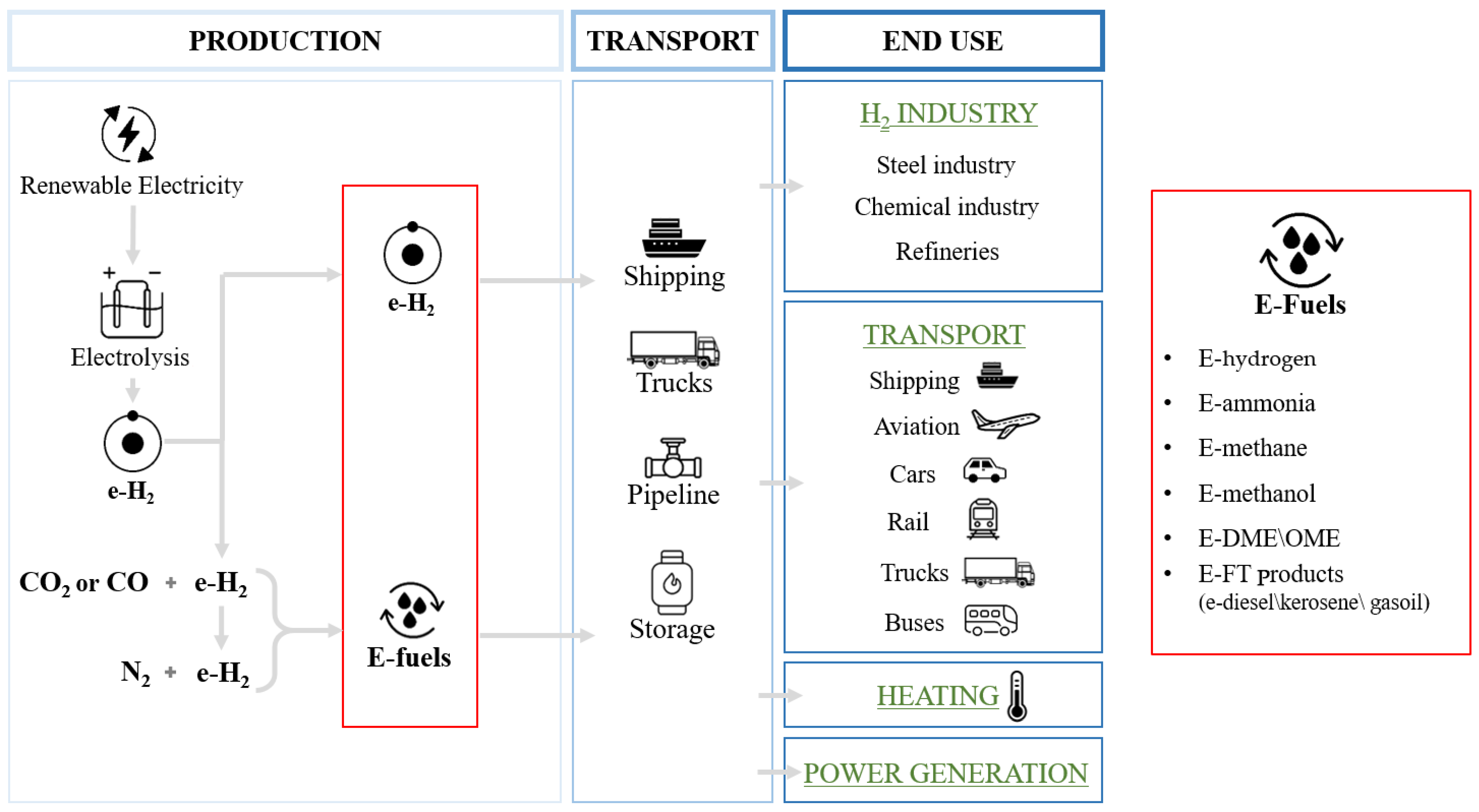
Figure 1. A schematic of renewable e-fuels processes, their transportation and some possible applications.
Energies 17 03995 g001
Figure 2. Outline of renewable e-fuel production technologies. Necessary raw materials are highlighted.
Energies 17 03995 g002
Figure 3. Popular hydrogen colour codes. Elaboration from [13].
Energies 17 03995 g003
Figure 4. AEC, PEM, and SOEC electrolyzers for hydrogen production through electrolysis.
Energies 17 03995 g004
Figure 5. Production methods of methane and associated colors based on the environmental impact linked to its production. Adapted from [14].
Energies 17 03995 g005
Figure 6. Production methods of methanol and associated colors based on the environmental impact linked to its production. Adapted from [14].
Energies 17 03995 g006
Figure 7. Typical distribution of crude oil obtained by the FT process. Adapted from [159,160].
Energies 17 03995 g007
Figure 8. Typical Fischer–Tropsch process for FT diesel production from syngas. Adapted from [13].
Energies 17 03995 g008
Figure 9. E-kerosene production and use cycle. Adapted from [13].
Energies 17 03995 g009
Figure 10. Production methods of ammonia and associated colors based on the environmental impact linked to its production. Adapted from [14].
Energies 17 03995 g010
Figure 11. Overlap between TRL and CRL. Adapted from [147].
Energies 17 03995 g011
Figure 12. Energy efficiencies for major conversion steps from electricity input to useful energy. Adapted from [15].
Energies 17 03995 g012
Figure 13. Lifecycle carbon intensity of e-diesel production via methanol, based on energy consumption and electricity carbon intensities taken from Joint Research Centre study [215]. Elaboration from [104].
Energies 17 03995 g013
Figure 14. GHG emissions for different fuels and transport applications as a function of carbon intensities of electricity used for battery charging, hydrogen production, and e-fuel synthesis. Note the different functional units on the y-axis among light vehicles (left, vehicle kilometers (vkm)), heavy trucks (middle, ton-km (tkm)), and aircraft (right, passenger-km (pkm)). Comparison of e-fuel options (CO2 from DAC or CCUS), hydrogen FCs (H2 from electrolysis), direct battery electrification, and fossil options, all based on technological advances projected for 2030 using the calculator life cycle assessment model [218] and calculator truck [219]. Vertical lines show electricity life cycle carbon intensities for selected geographic areas for 2018. The secondary x-axis (bottom) translates the carbon intensity of electricity into an equivalent share of renewable electricity generation (equal shares of wind and solar PV electricity, with the remaining nonrenewable generation being natural gas and coal electricity in equal shares). Data derived from [15].
Energies 17 03995 g014
Figure 15. Normalized electricity consumption versus BEVs for medium-sized passenger cars. Adapted from [32].
Energies 17 03995 g015
Figure 16. Equivalent CO2 vehicle emission depending on the electricity emission factor. Adapted from [32].
Energies 17 03995 g016
Figure 17. E-fuels, electro-chemical, electrical, and mechanical storage capacity over time. Based on [108].
Energies 17 03995 g017
Table 1. Characteristics of the main carbon capture technologies: post-combustion, precombustion, and oxyfuel combustion. Based on [77].
CCUS TechnologyPost CombustionPre CombustionOxyfuel Combustion
Technology maturityCommercialCommercialUnder development
ApplicationsCommercial and industrial power plantsNatural gas power plants and process industryAppropriate for some types of coal fuels
Advantages- Excellent for renovation of existing power plants;
- Matured technology
- Low gas volume;
- High pressure;
- High CO2 concentration;
- Less energy intensive;
- Easy CO2 separation;
- Lower water consumption
- More sustainable;
- No chemical operation;
- High efficiency;
- Reduction of NOx;
- Easy to capture CO2.
DisadvantagesLow CO2 partial pressure in flue gasHigh energy loss due to sorbent regenerationLow net power output
Capital costExcessive cost of system operationExcessive cost compared to a coal plant costExcessive cost of air separation system
Table 2. Mass and energy balance of the diesel production process by FT process (considering RWGS); quantities refer to 1 kg of diesel produced. Data processing from [103].
FlowQuantity
H2 consumption (total)0.493 kg
H2 consumption from RWGS0.169 kg
H2 consumption from FT and hydrocracking0.324 kg
CO2 consumption3.715 kg
CO equivalent2.364 kg
Gas burned0.237 kg
H2O production2971 kg
Power consumption1.90 MJ
Heat production9.22 MJ
Table 3. TRL [205] definition and associated MRL [206] and CRL [147].
Description TRLTRLMRLCRL
Basic principles observed1--
Technology concept formulated2--
Experimental proof of concept3--
Technology validated in lab41-
Technology validated in relevant environment (industrially relevant environment in the case of key enabling technologies)52-
Technology demonstrated in relevant environment (industrially relevant environment in the case of key enabling technologies)63-
System prototype demonstration in operational environment741
System complete and qualified852
Actual system is proven in operational environment (competitive manufacturing in the case of key enabling technologies or in space)963
Multiple commercial applications becoming evident locally although still subsidized. Verifiable data on technical and financial performance in the public domain driving interest from a variety of debt and equity sources however still requiring government support. Regulatory challenges being addressed in multiple jurisdictions--4
Market competition driving widespread deployment in the context of long-term policy settings. Competition emerging across all areas of the supply chain with commoditization of key components and financial products occurring--5
‘Bankable’ grade asset class driven by the same criteria as other mature energy technologies. Considered as a ‘blankable’ grade asset class with known standards and performance expectations. Market and technology risks do not drive investment decisions. Proponent capability, pricing, and other typical market forces driving uptake--6
Table 4. TRL, MRL, and CRL of different e-fuel production and CO2 capture pathways. Data source from Ref. [147], except those regarding e-H2 and CO2 capture (pre, post and oxy-fuel combustion) processing, which are from Ref. [32].
FuelPathwayTRLMRLCRL
e-H2AEC9--
PEM5–7--
SOEC3–5--
CO2 capturepost combustion9--
pre combustion7--
oxyfuel combustion7--
DAC adsorption/desorption631
DAC absorption/calcination52-
DAC adbsorption/electrodialysis41-
e-CH4Catalyt. methanation with low temperature electrolysis6–9 (DAC a)≥5≥2
Catalyt. methanation with high temperature electrolysis6 (SOEC b)31
e-CH3OHMethanol synthesis with low temperature electrolysis6–9 (DAC)≥5≥2
Methanol synthesis with high temperature electrolysis6 (SOEC)31
PtLFischer–Tropsch route with low temperature electrolysis6 (RWGS c)31
Fischer–Tropsch route with high temperature electrolysis6 (SOEC, RWGS)31
Methanol route with low temperature electrolysis6–9 (DAC)≥5≥2
Methanol route with high temperature electrolysis6 (SOEC)31
a DAC—Direct Air Capture. b SOEC—Solid Oxide Electrolysis Cell. c RWGS—Reverse Water Gas Shift.
Table 5. Energetic comparison of e-fuels and batteries in a medium-sized car. Data processing from [32].
Powertrain TypeEnergy VectorWTT EfficiencyTTW EfficiencyWTW EfficiencySpecific Electric Consumption for Medium Size Cars in WLTP [kWh/100 km]
BEVElectricity0.850.900.7719.5
ICEE-hydrogen (700 bar)0.550.350.1978.5
E-hydrogen (liquid)0.490.350.1788.2
E-methanol0.490.350.1786.9
E-diesel0.440.350.1598.1
E-ammonia0.480.350.1788.6
E-DME0.510.350.1883.6
E-methane (220 bar)0.470.350.1692.2
E-methane (liquid)0.460.350.1694.0
FCE-hydrogen (700 bar)0.550.50.2754.9
E-hydrogen (liquid)0.490.50.2461.7
E-methanol0.490.50.2560.9
E-ammonia0.480.50.2462.0
Table 6. Fossil fuel properties. Data from [125].
PropertiesFossil Fuels
Gasoline Diesel Kerosene LPG
Density (kg/m3)715–780815–855780–810540 (at 10 bar)
Boiling point (°C)25–215170–380151–301−41 to−0.5
LHV (MJ/L)31.2–32.235.3–3635.324.8
Octane number90–95--105–115
Cetane number-45–53--
Table 7. E-fuel properties. Data from [125,229].
ProprietàE-Fuels
FT-Diesel FT-Gasoline MtG FT-Kerosene MtJ * DME OME2–5 Methanol
MiscibilityIn dieselin gasolineIn gasolineIn jet fuelin jet fuelIn LPGIn dieselIn gasoline and diesel
Density (kg/m3)765–845720–755720–755730–770730–770gas961–1100792
Boiling point (°C)85–360210 (FBP) **210 (FBP) *205–300205–300−24.8105–28065
LHV (MJ/l)33.1–34.330–3330–33--18.3–19.319.5–19.715.4–15.6
Octane number-up to 85up to 85----110–112
Cetane number70–80----up to 5563–1105
* Methanol to jet. ** Final boiling point.
Table 8. Qualitative overview of e-fuels. Adapted from [27].
E-FuelsStorageAdditional InfrastructuresPowertrain Development
GASE-hydrogenDifficultYesNo **
E-methaneMedium *NoNo
LIQUIDE-ammoniaEasyYesYes
E-methanolEasyNoYes
E-DME/OMEEasyYesYes
E-diesel/gasoline/keroseneEasyNoNo
* E-methane could use most of the existing logistics, including transportation, storage, and distribution systems of natural gas, but storability is not as easy as for liquid molecules. ** FCEVs (fuel cell electric vehicles) are commercially available but are limited in number, and it is difficult to assess whether they will become a mainstream option.
Table 9. Different alternatives versus different key parameters. Adapted from [27].
Transport SectorsInfrastructureStorageInvestmentGHG Reduction
Fossil fuelsAllExistingEasyLowLow
ElectricityLDV/HDV *NewDifficultHighHigh
BiofuelsAll **ExistingEasyMediumHigh
E-fuelsAllExisting ***EasyHighHigh
* Limited by availability and cap in demand. ** LDV = light-duty vehicles; HDV = heavy-duty vehicles. *** Existing in the case of e-methane, e-methanol, e-gasoline, e-diesel or e-jet. Not existing for e-hydrogen, e-ammonia, or e-DME/OME.
Table 10. Potential primary uses of e-fuels. Xs represent an initial estimate of the relative potential role of different e-fuels in transport segments (no X represents no envisaged potential). Adapted from [27].
E-FuelsLight DutyHeavy DutyMaritimeAviationOther Sectors
GASE-hydrogenXXXXX X
E-methaneXXXXX XXX
LIQUIDE-ammoniaXXXXX
E-methanolXXXX
E-DME/OMEXXXXX
E-diesel/gasoline/keroseneXXXXXX *XXX **
* E-diesel. ** E-kerosene
Disclaimer/Publisher’s Note: The statements, opinions and data contained in all publications are solely those of the individual author(s) and contributor(s) and not of MDPI and/or the editor(s). MDPI and/or the editor(s) disclaim responsibility for any injury to people or property resulting from any ideas, methods, instructions or products referred to in the content.