Article

Pitch Actuator Fault-Tolerant Control of Wind Turbines via an L1 Adaptive Sliding Mode Control (SMC) Scheme

1
Department of Electrical Engineering, Vali-e-Asr University of Rafsanjan, Rafsanjan 7718897111, Iran
2
Department of Electrical Engineering, Amirkabir University of Technology, Tehran 1591634311, Iran
3
Department of Computer Science, Electrical Engineering and Mathematical Sciences, Western Norway University of Applied Sciences, 5528 Haugesund, Norway
4
Department of Electrical Engineering, Shams Gonbad Higher Education Institute, Gorgan 4971817615, Iran
*
Author to whom correspondence should be addressed.
Energies 2024, 17(16), 3963; https://doi.org/10.3390/en17163963
Submission received: 13 June 2024 / Revised: 22 July 2024 / Accepted: 2 August 2024 / Published: 9 August 2024

Abstract

:
Effective fault identification and management are critical for efficient wind turbine operation. This research presents a novel L 1 adaptive- SMC system designed to enhance fault tolerance in wind turbines, specifically addressing common issues such as pump wear, hydraulic leakage, and excessive air content in the oil. By combining SMC with L 1 adaptive control, the proposed technique effectively controls rotor speed and power, ensuring reliable performance under various conditions. The controller employs an adjustable gain and an integrated sliding surface to maintain robustness. We validate the controller’s performance in the FAST (Fatigue, Aerodynamics, Structures, and Turbulence) simulation environment using a 5-megawatt wind turbine under high wind speeds. Simulation results demonstrate that the proposed L 1 adaptive- SMC outperforms traditional adaptive- SMC and adaptive control schemes, particularly in the presence of faults, unknown disturbances, and turbulent wind fields. This research highlights the controller’s potential to significantly improve the reliability and efficiency of wind turbine operations.

1. Introduction

The transition to sustainable and clean energy sources has driven the rapid expansion of wind energy as a pivotal component of the global renewable energy landscape [1]. Wind turbines, serving as the workhorses of this transformation, are entrusted with the task of efficiently converting wind kinetic energy into electrical power [2]. However, the effective and reliable operation of wind turbines is confronted by multifaceted challenges [3,4], and among them, the occurrence of pitch actuator faults emerges as a prominent concern [5]. Wind turbine control strategies have evolved significantly over the years to maximize energy capture and ensure safe and efficient operation. Various control schemes, including pitch control, torque control, and combination strategies, have been proposed to address the dynamic nature of wind. Proportional–Integral–Derivative (PID) control is a commonly used technique in wind turbine control [6]. PID controllers regulate the pitch angle of turbine blades to maintain a consistent generator speed, optimizing power output [7]. While PID controllers are effective under normal operating conditions, they often struggle to accommodate actuator faults and disturbances [8]. Pitch actuator faults, such as sensor failures, actuator degradation, and mechanical faults, are among the most common issues affecting wind turbines. Identifying and addressing these faults is crucial for ensuring the reliability of wind turbine systems. Pitch actuator faults represent a significant operational challenge in wind turbines, affecting performance and reliability. These faults encompass sensor failures, actuator degradation, and mechanical issues [9]. Efficient fault detection and diagnosis techniques are crucial to achieve the desired reliability levels in modern wind turbines [10,11,12,13,14,15]. For these wind systems to operate efficiently in energy conversion, it is imperative to have an effective pitch actuator fault detection approach [16]. Fault identification methods can be broadly categorized into two main types: those rooted in models and those grounded in signal processing. Model-based fault identification utilizes system models, which can be mathematical as indicated in [17,18]. The detection of faults arises from the residuals formed by either the estimation of state variables or model parameters as discussed in [19] and its associated references. On the other hand, signal processing-oriented fault detection involves executing mathematical or statistical procedures on recorded measurements as exemplified in [20,21]. Accommodation strategies aim to adapt the control system to mitigate the effects of actuator faults. Fault-tolerant control techniques, such as adaptive control and SMC , have shown promise in this regard [22]. SMC is a prominent control strategy for nonlinear systems with uncertainties as cited in [23]. The fundamental design principle is to direct the paths of a closed-loop system to follow a predefined manifold or sliding surface. This surface is set up in advance to ensure that the error reaches zero when in sliding mode as outlined in [24]. Due to its benefits, like resistance to external disruptions, robustness against parameter shifts, and straightforward integration with power electronics, it has gained widespread use in wind turbine (WT) control as noted in [25]. A foundational method for controlling the wind turbine blade pitch angle is presented in [26], while a robust variant targeting rotor speed control amid uncertainties and disturbances is introduced in [27]. Another variant of SMC , which utilizes coefficients determined by the particle swarm optimization support vector machine method, is highlighted in [28]. This design demonstrated superior performance compared to model reference adaptive control (MRAC) when disturbances were present, although it did not factor in faults during its conceptualization [29,30]. In [31], a method utilizing a sliding mode observer was introduced, focusing on reconstructing multiple faults in wind turbines experiencing simultaneous actuator and sensor issues. Standard SMC has its limitations, such as the inability to guarantee finite-time convergence of system states and the troublesome chattering phenomenon. This chattering can undermine control accuracy, lead to mechanical wear, and cause considerable heat losses as noted in [32]. One method to achieve finite-time convergence is by substituting the linear sliding variable in standard SMC with a nonlinear alternative as highlighted in [33,34]. To address the chattering issue, integral terminal SMC methods have proven effective as mentioned in [35]. A specific method, the ITSMC technique, combined with gains that are automatically adjusted through a fuzzy system, was introduced for DFIG-WT in [36]. While this method enhanced the performance of wind turbines in the face of disturbances and faults, its computational requirements made implementation challenging. Another straightforward strategy to curb chattering involves decreasing the discontinuous component’s magnitude. Integrating an adaptation mechanism within the SMC strategy achieves this as demonstrated in [37]. SMC has gained attention in recent years for its ability to provide robust and precise control in complex dynamic systems. This control technique provides benefits such as enhanced tracking performance and increased robustness against uncertainties and disturbances. SMC has emerged as an attractive approach for handling nonlinear and uncertain systems. This control strategy introduces characteristics, allowing for enhanced tracking performance and robustness [38]. The application of SMC in wind turbines offers advantages such as improved tracking performance and robustness in the presence of uncertainties. This control scheme has shown promise in enhancing wind turbine performance, even under challenging conditions [39]. Wind turbine control systems are essential for optimizing energy capture, ensuring system stability, and safeguarding turbine components from extreme loads [40]. The pitch control system, specifically, is crucial for adjusting the angle of the turbine blades to accommodate changing wind conditions and sustain the generator’s rated power output [41]. When pitch actuator faults arise, such as sensor failures, actuator degradation, or mechanical issues, the consequences can be far reaching [42]. These faults not only compromise the performance and energy production of wind turbines but also pose potential threats to structural integrity and necessitate costly maintenance interventions [43].
Sliding mode control ( SMC ) and L 1 adaptive control are both powerful techniques for dealing with the complexities of wind turbine control, but each has its limitations. SMC is renowned for its robustness against system uncertainties and external disturbances, which is crucial for maintaining stability and performance in the face of faults. However, with SMC , its major drawback is the chattering phenomenon, which can lead to mechanical wear and reduced control precision. L 1 adaptive control, in contrast, provides rapid adaptation to changing system dynamics and uncertainties, ensuring that the system can quickly adjust to faults and disturbances. Despite uncertainties, it excels at achieving desired transient and steady-state performance, but it may lack the inherent robustness to large disturbances that SMC offers. The decision to combine SMC with L 1 adaptive control is based on the desire to leverage the strengths of both approaches. The SMC component contributes robustness and disturbance rejection capabilities, while the L 1 adaptive control component provides quick adaptation and minimizes chattering. This hybrid control strategy enhances the fault tolerance and reliability of the wind turbine system, offering a more comprehensive solution compared to traditional control methods that use either SMC or L 1 adaptive control alone.
In response to these challenges, this research endeavors to devise a comprehensive solution for mitigating pitch actuator faults in wind turbines. Our approach centers on the development and application of an innovative control strategy termed the “ SMC Scheme based on L 1 adaptive control”. By integrating SMC , L 1 adaptive control mechanisms, and fault tolerance strategies, we aim to enhance the reliability, efficiency, and robustness of wind turbines, particularly in the presence of pitch actuator faults and uncertainties. The main contributions of this paper can be outlined as follows:
  • To address the critical issue of pitch actuator faults in wind turbines and their detrimental impact on performance and reliability;
  • To introduce and elucidate the L 1 adaptive- SMC scheme as a novel and effective control strategy tailored for pitch actuator fault tolerance;
  • To evaluate and validate the proposed approach, the simulation results are analyzed for healthy and faulty conditions of the system.
  • To compare the performance of the proposed method with traditional control techniques, including adaptive- SMC and adaptive control, to demonstrate its superiority.
The remainder of this paper follows this structure: In Section 2, the modeling of the wind turbine system is discussed. Also, the fault model of the pitch actuator is described in Section 3. In Section 4, we present the control method and its stability analysis using Lyapunov theory. Section 5 evaluates the effectiveness of our proposed method and compares it to that of other methods. Finally, in Section 6, we will conclude with an overview of our contributions and avenues for future research, emphasizing the significance of innovative control strategies in advancing renewable energy systems.

2. Wind Turbine System

Figure 1 presents a detailed diagram of a wind turbine. The nacelle, positioned atop the tower, primarily consists of the aerodynamic rotor, drive-train, and generator. The rotor harnesses wind energy and transforms it into electricity within the nacelle. Although the wind propels the rotor at a slower pace, the drive-train within the generator accelerates this speed. The generator’s control system regulates the pitch angle of the rotor blade by exerting the designated electromagnetic torque on the pitch actuator. The pitch angle is determined using data from the tower’s speed and the generator shaft’s rotation speed, collected by an accelerometer fixed on the tower’s summit. Additionally, an anemometer situated at the nacelle’s peak records the wind’s velocity and direction [44].
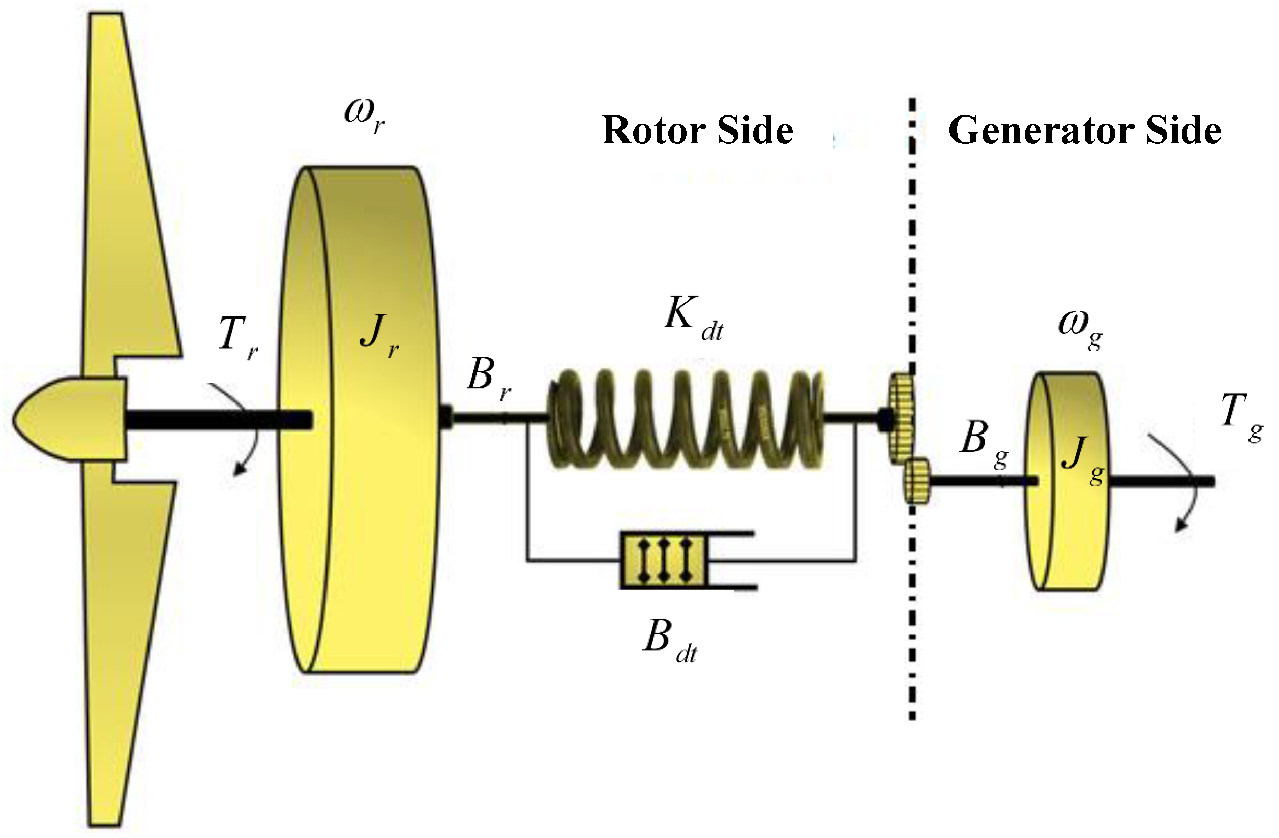
Figure 2 presents a simplified two-mass model of a wind turbine. In this instance, we represent the generator and the rotor using dual inertias. This two-mass representation works well for transient stability assessments of the turbine [45].

2.1. Aerodynamic Model

The aerodynamic forces acting on the rotor are mostly determined by the pitch control. As a consequence, the tower structure may vibrate and deflect due to a controller that is poorly built. The wind’s aerodynamic force powers the rotor’s functioning. Three main factors essentially control this force: the machine’s power curve characteristics, the machine’s capacity to adjust to variations in wind speed, and the machine’s intrinsic power accessible in the wind. Aerodynamics provides the following explanation for the collected wind power [46].
P a e r o = 1 2 · ρ · A · C p · V 3
where:
  • P: power extracted from the wind;
  • ρ : air density;
  • A: swept area of the turbine blades;
  • C p : power coefficient of the turbine;
  • V: wind speed.
C p is a function of the tip-speed ratio and the pitch angle. The tip-speed ratio is defined as the ratio of the speed of the tip of the blades to the speed of the wind. Adjusting the pitch of the blades can optimize C p for different wind speeds. The power coefficient, C p , is a function of the tip–speed ratio, λ , and the blade pitch angle, β . It can be represented by the equation [47].
C p ( λ , β ) = c 1 · ( c 2 / λ i c 3 β c 4 β 5 c c 6 ) · e c 7 / λ i + c 8 λ
where
  • λ i = 1 λ + 0.08 β 0.035 β 3 + 1 is the tip–speed ratio for each individual segment of the blade.
  • λ : is the tip–speed ratio.
  • β : is the blade pitch angle.
  • c 1 , c 2 , c 3 are coefficients determined based on the specific model and design of the wind turbine and its blades.
The aerodynamic torque T a applied to the rotor can be derived from the power extracted from the wind and the angular velocity of the rotor. Specifically, it is given by:
T a = P a e r o ω
where:
  • P a e r o : is the aerodynamic power extracted from the wind, which can be calculated using the aforementioned power coefficient and other aerodynamic parameters.
  • ω : is the angular velocity of the rotor in radians per second.
Substituting the expression for P a e r o into the torque equation will provide a detailed relationship between the aerodynamic torque, wind velocity, rotor speed, and blade design parameters.
We consider each actuator in a hydraulic pitch control system to be a linear second-order system characterized by the following transfer function [48]:
β β r = ω n 2 s 2 + 2 ζ ω n + ω n 2
The symbols ω n , ζ , and β r denote the natural frequency, damping ratio, and reference pitch angle, respectively. Figure 2 illustrates the mechanical component of the drive-train system as a nonlinear two-mass spring-damper system.
The state-space equations that describe its dynamic model are as follows [49]:
ω ˙ r = 1 J r P r ω r ω r D s + ω g D s N g θ K s ω ˙ g = 1 J g ω r D s N g ω g D s N g 2 + θ K s N g T g θ ˙ = ω r ω g N g
Here, θ represents the torsional angle. Table 1 provides the definitions of the other parameters along with their corresponding values for the reference turbine.
The input vectors and the state are specified as
x = ω r ω g θ β β ˙ T , u = β r
The wind turbine’s affine nonlinear dynamic model is stated as follows:
x ˙ = f ( x , x ˙ ) + g u
Here, x represents the state vector, x ˙ is the state derivative, and g signifies the coefficient of control input, whereas f ( x , x ˙ ) denotes the nonlinear component.
We can show that a diffeomorphism transformation exists, which simplifies the wind turbine system in (7) to a stable zero-dynamics normal form. Consequently, by analyzing the time derivative of e ˙ = ω ˙ r ω ˙ r * , we ensure the wind turbine system’s stability and nonsingularity throughout its entire operating range. Therefore, the second-order derivative of rotor speed dynamics can be expressed as follows [48]:
d 2 x 1 d t 2 = L f ( x ) + L g ( x ) u L f ( x ) = f 1 x 1 f 1 + f 1 x 2 f 2 + f 1 x 3 f 3 + f 1 x 4 f 4 + f 1 x 5 f 5 + f 1 U U ˙ L g ( x ) = f 1 x 5 g 5

2.2. Drive-Train Model

As aforementioned, Figure 2 depicts a schematic representation of a drive-train model, which commonly consists of a rotor and a generator, coupled by a drive-train.

2.2.1. Rotor Dynamics

The equation governing the rotor dynamics can be given by
J r d ω r d t = T r T t
where T t is the torque on the drive-train (spring-damper system) due to the rotor, ω r is the rotor angular velocity, T r is the torque applied on the rotor by the wind, and J r is the moment of inertia of the rotor [48].

2.2.2. Generator Dynamics

The equation governing the generator dynamics is
B g d ω g d t = T g + T t
Here, T t is the torque on the drive-train due to the generator, and it acts in the opposite direction to that from the rotor. ω r is the generator angular velocity, T g is the generator torque, and B g is the moment of inertia of the generator [48].

2.2.3. Drive-Train Dynamics (Spring-Damper System)

The torque on the drive-train due to the rotor and generator can be formulated as
T t = K d × B r + B d × ( ω r ω g )
where T t is the torque on the drive-train, K d is the drive-train stiffness, B r is defined as the difference in angular displacements between the rotor and the generator, B d is the damping factor, ω r is the rotor speed, and ω g is the generator speed. The dynamics of the turbine servo motor and the electrical components have been omitted in the control process design [48].

2.3. Pitch Actuator Model

Figure 3 represents a block diagram of a pitch actuator model with its control system.
Based on the given figure, the pitch actuator model in the Laplace domain can be formulated as follows:
  • First-order system: This block models the pitch actuator’s dynamics. The transfer function for the first-order system is:
    G ( s ) = 1 τ s + 1
    where τ is the time constant, ans s is the Laplace variable.
  • Saturation: This block ensures that the actuator’s output does not exceed (or fall below) specified limits. While saturation can be represented mathematically in various ways, in block diagram form, it is typically a nonlinear element.
  • Rate Limiter: This block restricts the rate of change of the actuator’s output.
Using these elements, the overall system, when linearized, can be described by the transfer function G ( s ) , but it is crucial to remember that the saturation and rate limiter introduce nonlinear behaviors that might require more sophisticated analysis techniques when considering their effects on system behavior.

3. Faults Model of Pitch Actuator

In general, defects are classified into two types, incipient and sudden, based on their temporal profile. Incipient flaws develop gradually over time, while abrupt faults arise abruptly and without warning. Although sudden faults are often straightforward to identify, they may have significant consequences for the system. In terms of severity, flaws may be categorized as either severe or nonextreme. In the case of severe problems, prompt measures such as off-grid procedures or shutdowns are implemented. However, in less severe situations, fault-tolerant control systems may be used to ensure that the turbine operates at an acceptable level of performance. Research indicates that a significant proportion of failures are of a modest kind, with the most common failures occurring in the pitch/hydraulic system [48].
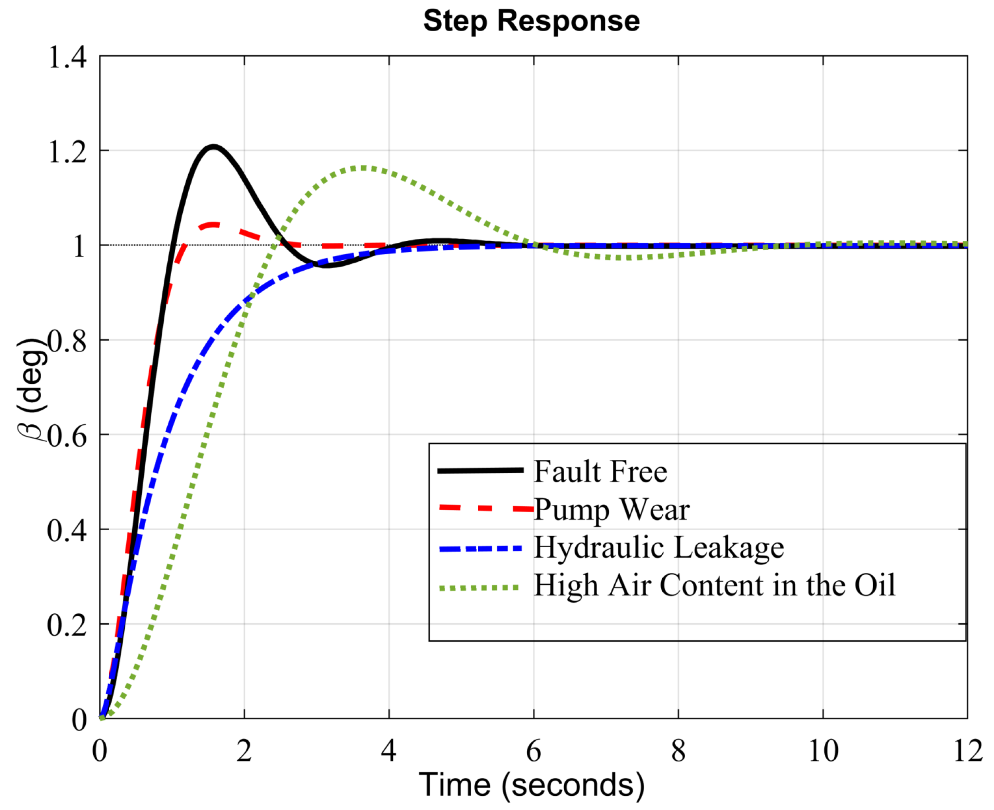
As illustrated in Figure 4, the hydraulic pitch system mainly comprises a pump, several valves, and a blade pitch motion mechanism. The controller receives the difference between the actual and desired rotor speeds and sends a control signal to a servo valve, which adjusts the actuator’s position. A range of factors, either related to the control system or the hydraulic subsystem, can cause pitch system problems. The control subsystem encounters sensor issues, while the hydraulic subsystem is frequently impacted by pump degradation, hydraulic leakage, and excessive air content in the oil. The main shortcomings of the hydraulic pitch actuators are high air content in the oil, pump wear, and hydraulic leakage. These issues affect the system dynamics in different ways, which is reflected in the natural frequency ( ω n ) and damping ratio ( ζ ) of the pitch system. Table 2 shows the quantitative values of the actuator dynamic parameters for the referenced wind turbine model.

3.1. Pump Wear

Pump wear, which begins as an initial fault, gradually progresses and leads to a reduction in pump pressure. This change affects the dynamics of the pitch system in the following ways:
β ¨ ( t ) = 2 ζ ^ ( t ) ω ^ n β ˙ ( t ) ω ^ n 2 ( t ) β ( t ) + ω ^ n 2 ( t ) β r t ζ ^ ( t ) = 1 γ p w ( t ) ζ + γ p w ( t ) ζ p w ω ^ n ( t ) = 1 γ p w ( t ) ω n + γ p w ( t ) ω n , p w
where β ¨ ( t ) is the pitch acceleration, ζ ^ ( t ) is the estimated damping ratio over time, ω ^ n is the estimated natural frequency over time, β ˙ ( t ) is the pitch velocity, β ( t ) is the pitch angle, and β r t is the reference pitch angle. γ p w ( t ) represents the wear level of the pump, ζ is the nominal damping ratio, and ζ p w is the damping ratio due to pump wear. ω n is the nominal natural frequency, and ω n , p w is the natural frequency due to pump wear. 0 γ p w ( t ) 1 represents the wear level. A value of zero represents the standard condition, while the maximum limit corresponds to 75% of the pump pressure.

3.2. Hydraulic Leakage

Hydraulic leakage, an early-stage problem that develops more quickly than pump wear, results in a substantial pressure drop of up to 50%. This issue alters the system parameters in the following ways:
ζ ^ ( t ) = 1 γ h l ( t ) ζ + γ h l ( t ) ζ h l ω ^ n ( t ) = 1 γ h l ( t ) ω n + γ h l ( t ) ω n , h l
where γ h l ( t ) represents the level of the hydraulic leakage, and ζ h l is the damping ratio due to hydraulic leakage, and ω n , h l is the natural frequency due to hydraulic leakage. The value of γ h l ( t ) is between 0 and 1, exclusively. Under normal circumstances, the value of γ h l ( t ) is 0. However, when there is a 50% decrease in hydraulic pressure, the value of γ h l ( t ) becomes 1. Insufficient hydraulic pressure prevents the system from moving the blades, causing the actuator to become stuck in its current position, resulting in blade seizure.

3.3. High Air Content in Oil

Excessive air content in the oil is another early-stage defect that significantly impacts the system:
ζ ^ ( t ) = 1 γ h a ( t ) ζ + γ h a ( t ) ζ h a ω ^ n ( t ) = 1 γ h a ( t ) ω n + γ h a ( t ) ω n , h a
where γ h a ( t ) represents the level of the high air content in oil, and ζ h a is the damping ratio due to the high air content in oil, and ω n , h a is the natural frequency due to the high air content in oil. Contrary to prior faults, the high air content in oil has the ability to dissipate. γ ˙ h a ( t ) may also have negative values. The γ h a ( t ) values of zero and one correspond to air content percentages of 7% and 15%, respectively. If the hydraulic leaking continues, it is possible for the pitch actuators to lose control. In order to avoid this scenario, it is essential to identify the problem prior to the hydraulic pressure decreasing to 50% of its designated amount.

4. Proposed Control Scheme

In this section, we outline the details of our proposed L 1 adaptive- SMC scheme for fault-tolerant control of pitch actuators in wind turbines. The control scheme is designed to address pitch actuator faults, adapt to varying wind conditions, and enhance overall turbine performance. The “ L 1 Adaptive- SMC Scheme” represents a novel and comprehensive approach to address pitch actuator faults in wind turbines. This section offers a comprehensive analysis of the key components and design principles of this innovative control strategy.

4.1. Standard L 1 A C Problem

This section explains the L 1 A C issue and its key phases. Three main processes can be used to synthesize the controller [51].

4.1.1. State Predictor

x ^ ˙ ( t ) = A m x ^ ( t ) + B w ^ ( t ) u a d ( t ) + θ ^ T ( t ) x ( t ) + σ ^ ( t ) y ^ ( t ) = C x ^ ( t ) ,
where x ^ ( t ) is the state prediction, A m is the system matrix, B is the input matrix, u a d ( t ) is the adaptive control input, and C is the output matrix. w ^ ( t ) , σ ^ ( t ) , and θ ^ T ( t ) R m are the adaptive estimations for w , σ ( t ) , and θ T ( t ) .

4.1.2. Adaptation Laws

The adaptation laws listed below can be used to estimate the adaptive estimations of w ^ ( t ) , σ ^ ( t ) , and θ ^ T ( t ) [51]:
θ ^ ˙ ( t ) = Γ Proj θ ^ ( t ) , x ˜ T ( t ) PB x ( t ) , θ ^ ( 0 ) = θ ^ 0 σ ^ ˙ ( t ) = Γ Proj σ ^ ( t ) , x ˜ T ( t ) PB , σ ^ ( 0 ) = σ ^ 0 w ^ ˙ ( t ) = Γ Proj w ^ ( t ) , x ˜ T ( t ) PB u a d ( t ) , w ^ ( 0 ) = w ^ 0 ,
in which the positive-definite and symmetric matrix P = P T in (17) is the equation solution A m T P + P A m = Q for every arbitrary positive-definite and symmetric matrix Q = Q T . Additionally, x ˜ ( t ) = x ^ ( t ) x ( t ) represents the state prediction error, and Γ R + denotes the adaptation gain.
Remark 1.
The projection operator Proj ( . , . ) in (17) ensures w ^ ( t ) [ w l , w h ] with 0 w l w h , σ ^ ( t ) σ b , and θ ^ ( t ) θ b . The definition of the projection operator is [51]:
Ω c = θ R n | f ( θ ) c , 0 c 1 f ( θ ) = ( ϵ θ ) θ T θ θ m a x 2 ϵ θ θ m a x 2 Proj ( θ , y ) = y i f f ( θ ) < 0 , y i f f ( θ ) 0 a n d f T y 0 , y f f f f , y i f f ( θ ) 0 a n d f T y > 0 ,
where Ω c , ϵ θ > 0 , θ m a x , and f ( θ ) are the convex set with the smooth bound, the projection threshold, the upper bound of vector θ, and the uniform convex function, respectively.

4.1.3. Control Law

The adaptive feedback system’s control law is computed using (19)
u a d ( s ) = K D ( s ) η ^ ( s ) ,
and here, the following signal’s Laplace transform is represented by η ^ ( s ) :
η ^ ( t ) = w ^ ( t ) u a d ( t ) + η ^ 1 ( t ) r g ( t ) .
In (19), (20), η ^ 1 ( t ) = θ ^ T ( t ) x ( t ) + σ ^ ( t ) , r g ( s ) = K g R ( s ) . R ( s ) , K g , and K > 0 are the Laplace transform r ( t ) , the input gain ( K g = C A m 1 B 1 ), and the feedback gain, respectively. Diagonal matrix D ( s ) (with elements containing strictly-proper transform functions) is used to design low-pass filter C ( s ) as follows:
C ( s ) = w K D ( s ) + ( I m + w K D ( s ) ) 1 ,
where C ( s ) is a stable filter with the DC gain of 1 m ( C ( 0 ) = 1 m ) [51].

4.2. L 1 Adaptive- SMC with State Predictor

Let = ω r ω r * be the tracking error of the rotor speed. The NFITS surface may be defined as:
S = α 1 e + e ˙ + α 2 0 t e c + e + e l / b d t
where the constant parameters are α 1 and α 2 . In order for the controller to meet 1 < l / b < 2 and have a nonsingular attribute, c > l / b , l, and b must be selected as odd integers.
The sliding variable is guided to the sliding surface by the SMC -based control rule, ensuring it remains close to the surface. The law comprises a discontinuous term that counteracts the effects of uncertainty and disturbances, along with a continuous component that stabilizes the nominal system:
u = u C + u D
where u C and u D stand for equal-control words that discontinue. To derive a comparable control law, the first derivative of the sliding surface with respect to time must be set to zero. This yields the following continuous control law:
S ˙ = α 1 e ˙ + e ¨ + α 2 e c + e + e l / b = 0 u C = L ^ g 1 L f + α 1 e ˙ + α 2 e c + e + e l / b
As previously mentioned, this control rule does not mitigate the effects of disturbances. The following error dynamics are produced when replaced in (8), where it is stated that the tracking error cannot converge to zero, no matter how large its magnitude:
e ¨ + α 1 e ˙ + α 2 e c + e + e l / b d = 0
We solve this challenge by adding a discontinuous term u D and rewriting the overall control rule in the following manner:
u = L ^ g 1 L ^ f + α 1 e ˙ + α 2 e φ + e + e l / b + d ^ + γ 1 S + γ 2 sgn ( S )
where d, γ 1 , and γ 2 are positive constant parameters, while L ^ g , L ^ f , and d ^ represent the estimates of L g , L f , and disturbances. To accommodate the impact of unknown external disturbances, γ 2 must be selected so that it exceeds its upper limit. This high gain value aggravates chattering, as it increases the number of discontinuous terms. We build a nonlinear disturbance state predictor to address this problem.
Remark 2.
The controller ensures reliable performance under a range of circumstances by using an adjustable gain and an integrated sliding surface. Below, we provide a brief description of these components and their functions within the controller:
  • Adjustable gain: In the L 1 adaptive- SMC scheme, the adjustable gain refers to the mechanism by which the controller dynamically adjusts the control gains in response to varying system conditions and disturbances. This adaptability allows the controller to maintain optimal performance even as the system parameters or external conditions change. The adjustable gain ensures that the control input is sufficient to counteract disturbances and maintain desired performance without causing excessive control effort or chattering.
  • Integrated sliding surface: The integrated sliding surface is a key component of the SMC technique. In this context, the sliding surface is a predefined manifold in the system’s state space. The control objective is to drive the system’s state trajectory onto this surface and hold it there, ensuring robust performance despite uncertainties and disturbances. The integrated sliding surface combines the traditional sliding mode control approach with additional terms from the L 1 adaptive control, which helps to reduce chattering and improve the system’s response to faults and disturbances.
By integrating these two components, the L 1 adaptive- SMC scheme achieves a balance between robustness and adaptability. The sliding surface provides a robust framework for disturbance rejection, while the adjustable gain allows the controller to quickly adapt to changes, enhancing the overall fault tolerance and reliability of the wind turbine control system.

4.3. State Predictor of Nonlinear Disturbance

Assumption 1.
The temporal derivative of unknown external disturbances is limited and has an upper bound.
To estimate this disturbance, the following architecture of a nonlinear disturbance state predictor is used [48]:
h ˙ = K h κ K ω ˙ r + L f + L g u d ^ = h + K ω ˙ r
where K > 0 and h stand for the predictor’s internal state and gain, respectively. The definition of the disturbance estimate error is:
d ˜ = d d ^
We can express the time derivative of (28) as follows using (8) and (27):
d ˜ ˙ = d ˙ d ^ ˙ = h ˙ K ω ¨ r = K d ^ K ω ˙ r + K K ω ˙ r + L f + L g u K L f + L g u + d = K d ˜
Lemma 1.
Assuming Assumption 1, the disturbance estimator from (27) can asymptotically track the real disturbance with positive predictor gain.
This lemma indicates that by choosing a positive value for the predictor gain, we can achieve asymptotic stability of the estimation error dynamics and accurately evaluate the unknown exogenous disturbances. Moreover, increasing the predictor gain values can expedite the convergence rate of the error dynamics. By defining Γ ^ = L ^ f / L ^ g and V ^ = L ^ g , we can rewrite the control rule (26) as follows:
u = V ^ α 1 e ˙ + α 2 e φ + e + e l / b + d ^ + γ 1 S m + γ 2 sgn S m + Γ ^ u = C ( s ) u ( s ) Γ ^ ˙ = γ g Proj Γ ^ ( t ) , S α sat ( S ) = S m , Γ ^ ( 0 ) = Γ ^ 0 V ^ ˙ = γ g Proj V ^ ( t ) , α 1 e ˙ + α 2 e φ + e + e l / b + d ^ + γ 1 S m + γ 2 sgn S m S m , V ^ ( 0 ) = V ^ 0 sat ( S ) = sgn ( S ) if | S | > α S α if | S | α
The thickness of the boundary layer is denoted by the small positive number α . According to the adaptation rules, the adaptation response will cease when the sliding variable enters the boundary layer. This prevents the overestimation of unknown parameters and reduces chatter.
Remark 3.
It is evident from the suggested control rule (30) that the adaptive control parameter V influences both discontinuous and continuous control terms. Therefore, both control terms aid in the system’s accommodation if a defect arises. This lessens the likelihood of chatter by moderating the role of the discontinuous phrase.
Assumption 2.
The exogenous disturbance’s estimating error is limited, and ε = sup t > 0 | d ˜ | .
Theorem 1.
If the wind turbine has a nonsingular fast integral-type terminal sliding surface (22), a nonlinear disturbance state predictor (27), and a designed adaptive control law (30), it can achieve asymptotically stability despite the presence of unknown external disturbances and parametric uncertainties.
Proof.  
The following is the selection of a positive-definite Lyapunov function:
V = 1 2 S m T S m + V 1 V ˜ 2 + V 1 Γ ˜ 2 + d ˜ 2 = 1 2 S m T S m + V 1 ( V ^ V ) 2 + V 1 ( Γ ^ Γ ) 2 + d ˜ 2
Calculating the Lyapunov function’s time derivative yields
V ˙ = S m T V 1 Γ V 1 Γ ^ V 1 V ^ α 1 e ˙ + α 2 e φ + e + e l b d ^ V 1 V ^ γ 1 S m V 1 V ^ γ 2 sgn S m + d + α 1 e ˙ + α 2 e φ + e + e l b + V 1 ( V ^ V ) V ^ ˙ + V 1 ( Γ ^ Γ ) Γ ^ ˙ K d ˜ 2 = V 1 ( Γ ^ Γ ) Γ ^ ˙ S m + S m T V 1 V ^ 1 α 1 e ˙ + α 2 e φ + e + e l b d ^ + V 1 V ^ 1 V ^ ˙ + S m T d ˜ S m T V 1 V ^ γ 1 S m + γ 2 sgn S m K d ˜ 2
Using (32) with the adaptation laws substituted produces:
V ˙ = S m T γ 1 S m S m T γ 2 sgn S m + S m T d ˜ K d ˜ 2
with the knowledge that S m S m = S m 2 , S m sgn S m = S m [10], and γ 2 ( ε + η ) where ε = sup t > 0 | d ˜ | , then
V ˙ γ 1 S m 2 η S m K d ˜ 2 γ 1 S m 2 S m η + K d ˜ 2 S m
We can reduce (34) as follows because we can obtain η > α d ˜ 2 S m + δ m , where δ m is a positive arbitrary constant, by choosing a switching gain η :
V ˙ < δ m S m
The proposed L 1 adaptive SMC control scheme and nonlinear disturbance state predictor can guarantee the stability of the closed-loop wind turbine system, even when faced with unknown exogenous disturbances, uncertainties, and faults. Consequently, the standard reachability condition described in [48] will be met after a finite amount of time.

5. Simulation-Based Evaluation and Discussion of the Results

We conducted a series of simulations under both faulty and healthy conditions to validate the effectiveness of the proposed controller. The controller is implemented on a detailed model in the FAST (Fatigue, Aerodynamics, Structures, and Turbulence) simulator, a robust tool for wind turbine control verification. Our controller is designed based on a simplified two-mass model of wind turbines. For brevity, this study presents only the results from the FAST simulations.
In Turbsim, the turbine is exposed to distinct wind fields, each with a mean speed of 18 m/s and a turbulence intensity of 5%. To simulate measurement noise, Gaussian noise with a zero mean and a specified standard deviation is added to the output. The noise standard deviation varies depending on the sensor type and measurement complexity. Three distinct actuator faults are introduced to the system: pump wear, excessive air content in the oil, and hydraulic leakage. The impacts of each actuator fault on the controller’s performance are examined independently. Figure 5 illustrates the pitch system’s step response to each fault. The effects of faults are simulated by altering the pitch actuator dynamics’ natural frequency and damping ratio. In the simulations, the controller filter is configured as follows:
C ( s ) = 1 τ 1 s + 1 , τ = 0.55
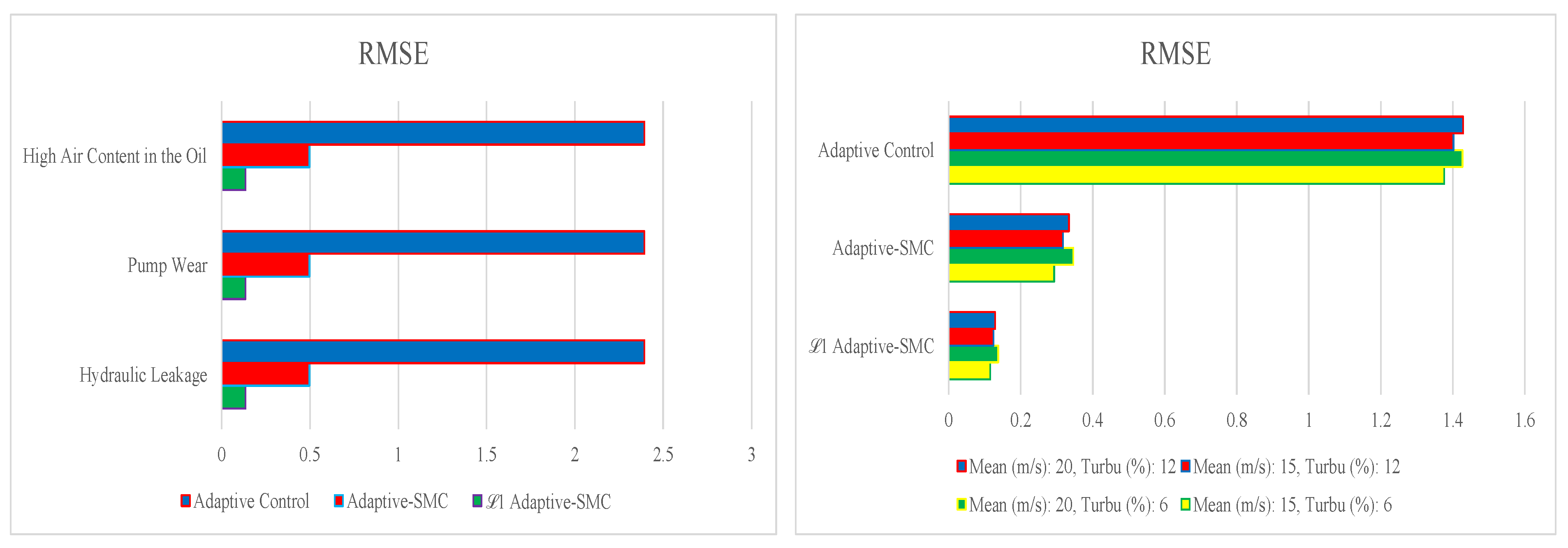
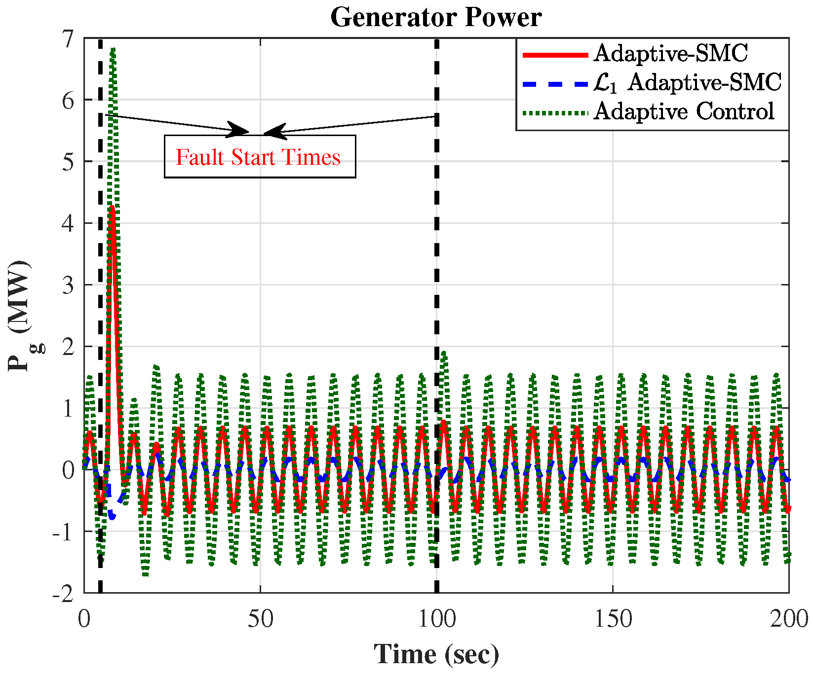
We impose the pump wear actuator fault at t = 5 and hydraulic leakage actuator fault at t = 100 s to verify the fault tolerantness of the proposed method. In order to simulate measurement noise, a Gaussian noise with a mean of zero and a specified standard deviation is introduced into the output. The noise standard deviation varies depending on the type of sensor and the measurement difficulty. Additionally, we run simulations for the system with two other controllers, adaptive- SMC [29] and adaptive control [30], and compare their results to demonstrate the performance of the proposed control scheme. Figure 6 illustrates the RMS of the error of rotor speed for the wind turbine pitch control system under the influence of each controller, exposed to various wind patterns and faults. The turbine is subjected to four distinct wind profiles created using Turbsim, characterized by mean speeds of 15 and 20 m/s and turbulence intensities of 6% and 12%. The results clearly demonstrate that while the three faults have a similar impact on each controller, different controllers respond differently when faults occur. The L 1 adaptive- SMC and adaptive- SMC exhibit higher accuracy compared to the adaptive control, with the L 1 adaptive- SMC maintaining an error that remains nearly zero.
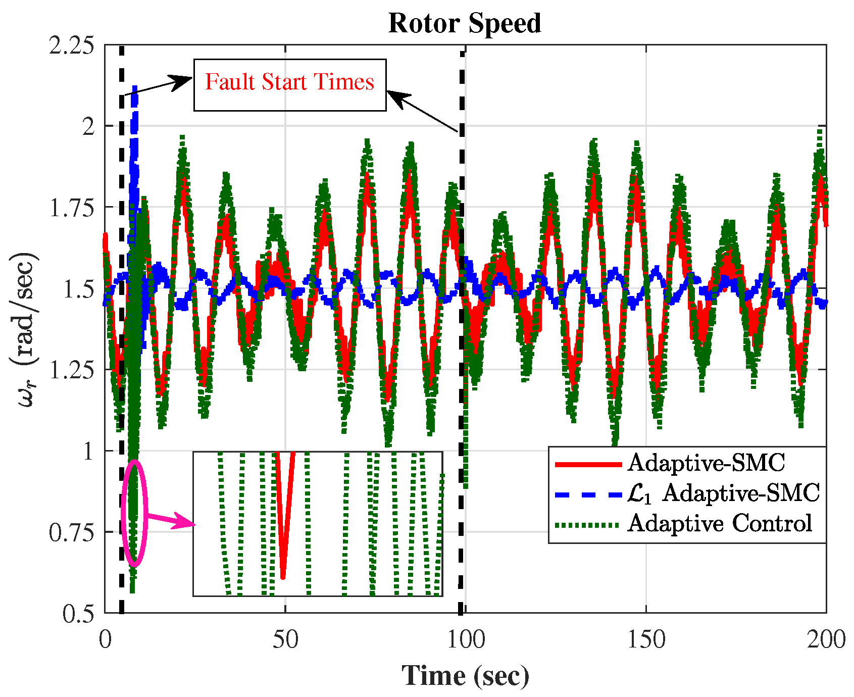
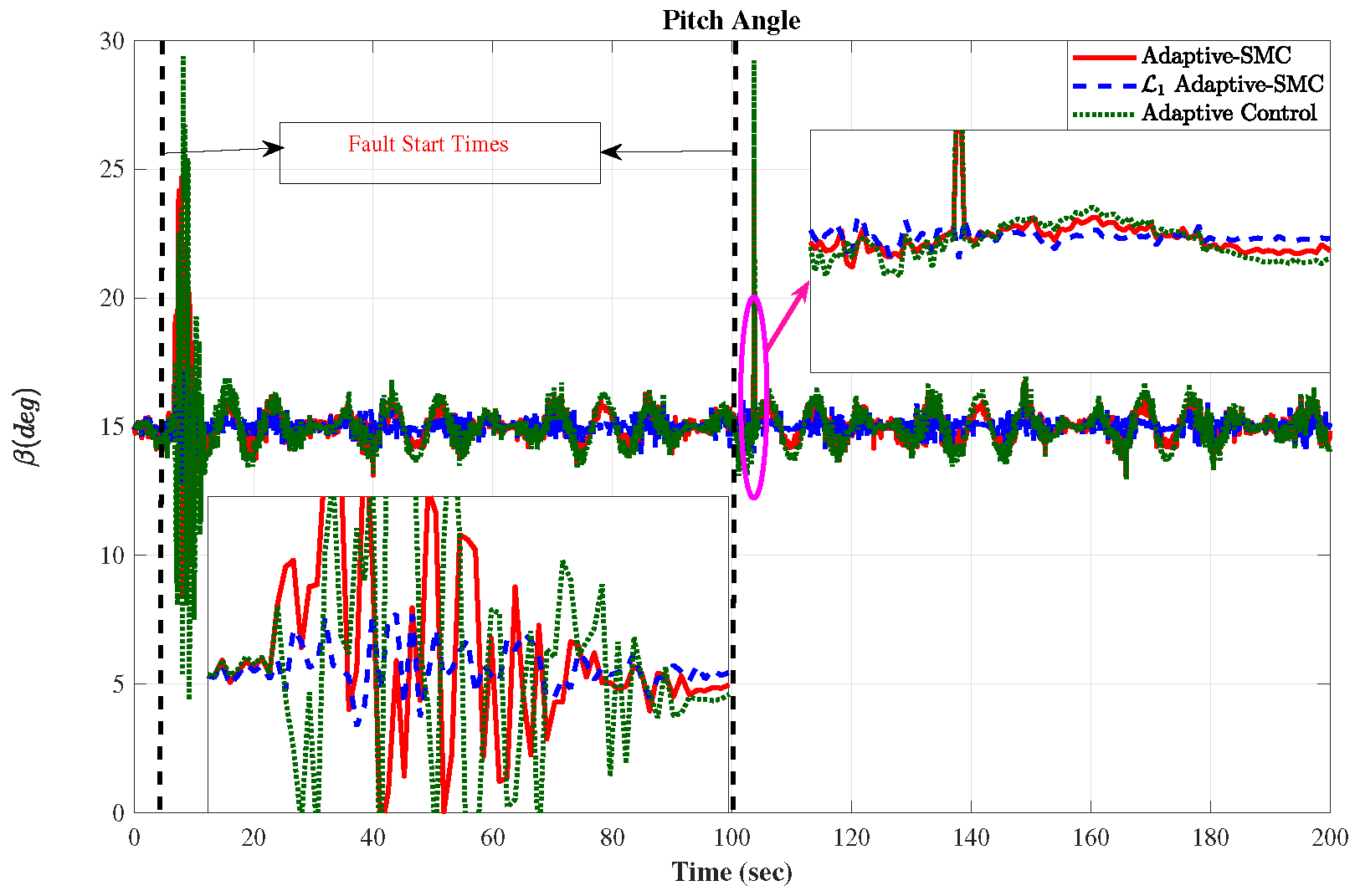
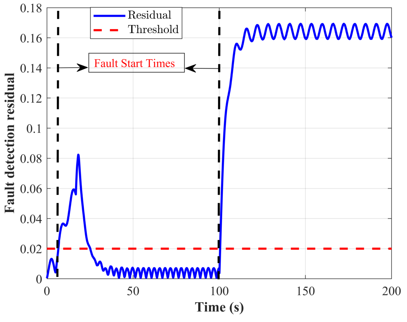
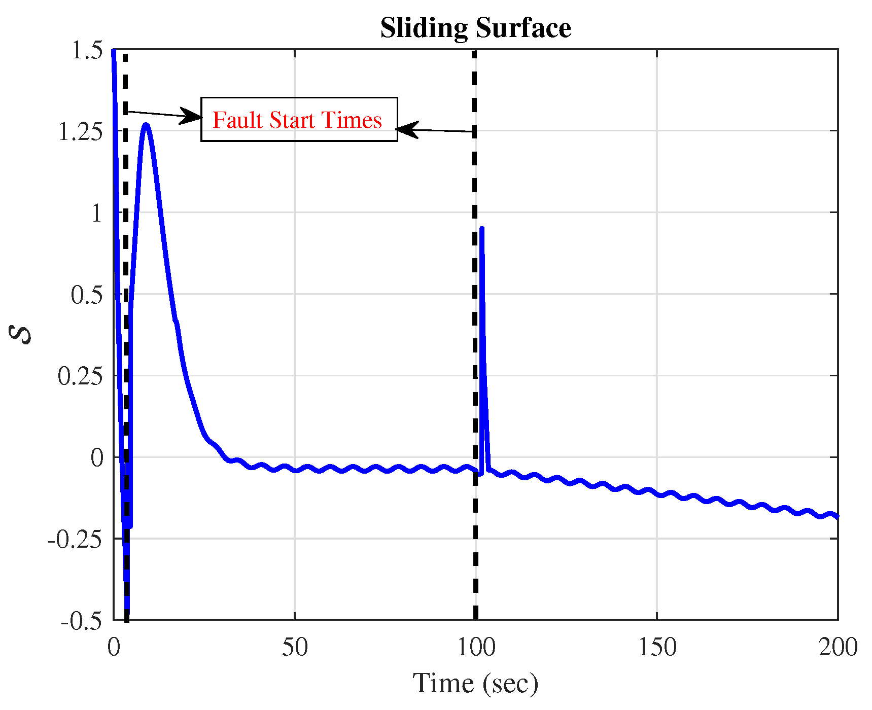
For a more complete look at how well the controllers work, see Figure 7, Figure 8, Figure 9 and Figure 10, which show the generator power ( P g ) and speed ( ω g ) along with the rotor speed ( ω r ) and pitch angle ( β ) for each of the three types: L 1 adaptive- SMC , adaptive- SMC , and adaptive control. The results of the proposed approach show minimal variation when three controllers perform the tracking, and this pattern continues even after the fault occurs. We evaluate the fault detection system by studying the residuals derived from the suggested technique. Figure 11 depicts the residuals generated by the fault detection system during the simulation. Residuals are the difference between the expected system behavior, based on the model, and the state predictor behavior. In this study, residuals are calculated by comparing the state predictor of the wind turbine control system with the actual model. It should be mentioned that in determining the fault, we use the predictor of the state designed in the L 1 adaptive control and the norm of residue resulting from the error signal. When a system malfunctions, like a pump wear fault that occurs at t = 5 s or a hydraulic leakage fault that occurs at t = 100 s, the residuals surpass the predetermined thresholds, signifying the existence of faults. The figure displays these thresholds as horizontal dashed lines. On the other hand, when the wind is normal or with turbulence but there are no faults, the residuals stay within the limits. This shows that the system can tell the difference between normal operational disturbances caused by turbulence and real faults. However, in determining the turbulent wind, it is performed in accordance with Section 4.3 (state predictor of nonlinear disturbance) and the turbulent wind is predicted as an external disturbance. The important point is that according to Assumption 1 in Section 4.3, the limit of estimation disturbance should always be considered lower than the fault threshold limit. Furthermore, Figure 12 demonstrates that the sliding surface convergence is near zero.
Table 3 shows that the actual time and CPU time required for implementing the proposed controller are lower than those of the other controllers. This proves that the proposed controller is capable of handling real-time applications.

6. Conclusions and Discussion

This paper proposes an L 1 adaptive SMC (a type of AFTC ). The proposed method employs L 1 adaptive control to protect the wind turbine pitch system from actuator problems, external disturbances, and unknowns. The L 1 adaptive control uses SMC to estimate uncertainty and provides an easy-to-implement framework without the need for a model. Furthermore, the proposed method generates an effective control command that can negate the impact of external disruptions, flaws, and uncertainties. The proposed structure not only reduced the side effect of chattering in the discontinuous control term, but it also successfully separated and accommodated problems. We conducted a series of simulations with turbulent wind fields and actuator defects in the FAST (Fatigue, Aerodynamics, Structures, and Turbulence) environment, both under healthy and defective conditions. We then compared the performance of the proposed controller with that of two other controllers: an adaptive control scheme and an adaptive SMC . The results validated the proposed controller’s superiority and effectiveness.
To enhance the accuracy and convergence rate of the suggested structure, further research might include dynamic SMC . We could also implement an extended state predictor to estimate all uncertainties and disturbances. A new adaptive rule can adaptively update the sliding mode-based control’s switching gain, ensuring it remains independent of uncertainties.

Author Contributions

Conceptualization, methodology, formula analysis, writing original draft, A.F., H.G.Z., H.A.; supervision, writing-review and editing M.G. and O.R.S. All authors have read and agreed to the published version of the manuscript.

Funding

This research received no external funding.

Data Availability Statement

The original contributions presented in the study are included in the article, further inquires can be directed to the corresponding author.

Conflicts of Interest

The authors declare no conflict of interest.

Abbreviations

The following abbreviations are used in this manuscript:
SMC       Sliding Mode Control
AFTC       Active Fault-Tolerant Control
L 1 adaptive- SMC        L 1 Adaptive Sliding Mode Control
RMS       Root Mean Square
DFIG       Doubly Fed Induction Generator
ITSMC       Integral Terminal Sliding Mode Control
NFITS       Nonsingular Fast Integral-Type Terminal Sliding

References

  1. Olabi, A.G.; Obaideen, K.; Abdelkareem, M.A.; AlMallahi, M.N.; Shehata, N.; Alami, A.H.; Mdallal, A.; Hassan, A.A.M.; Sayed, E.T. Wind Energy Contribution to the Sustainable Development Goals: Case Study on London Array. Sustainability 2023, 15, 4641. [Google Scholar] [CrossRef]
  2. Chaudhuri, A.; Datta, R.; Kumar, M.P.; Davim, J.P.; Pramanik, S. Energy Conversion Strategies for Wind Energy System: Electrical, Mechanical and Material Aspects. Materials 2022, 15, 1232. [Google Scholar] [CrossRef]
  3. Rezazadeh, A.; Bagheri, H.R.; Sarabadani, A.A. The Best Planning For a Grid-Connected Microgrid Takes Into Account Load and Renewable Generation Uncertainty As Well As Battery Storage. Trans. Mach. Intell. 2018, 1, 19–30. [Google Scholar] [CrossRef]
  4. Kheirabadi, M.N.; Khaligh, V.; Ghezelbash, A. The Role of Renewable Energies on Energy Security in Iran (In three fields of resources, production and distribution of energy). Trans. Mach. Intell. 2019, 1, 10–23. [Google Scholar]
  5. Acho, L.; Pujol-Vázquez, G. Data Fusion Based on an Iterative Learning Algorithm for Fault Detection in Wind Turbine Pitch Control Systems. Sensors 2021, 21, 8437. [Google Scholar] [CrossRef] [PubMed]
  6. Hu, X.; Tan, W.; Hou, G. PIDD2 Control of Large Wind Turbines’ Pitch Angle. Energies 2023, 16, 5096. [Google Scholar] [CrossRef]
  7. Chavero-Navarrete, E.; Trejo-Perea, M.; Jáuregui-Correa, J.C.; Carrillo-Serrano, R.V.; Ronquillo-Lomeli, G.; Ríos-Moreno, J.G. Pitch Angle Optimization for Small Wind Turbines Based on a Hierarchical Fuzzy-PID Controller and Anticipated Wind Speed Measurement. Appl. Sci. 2021, 11, 1683. [Google Scholar] [CrossRef]
  8. Asgharnia, A.; Jamali, A.; Shahnazi, R.; Maheri, A. Load mitigation of a class of 5-MW wind turbine with RBF neural network based fractional-order PID controller. ISA Trans. 2020, 96, 272–286. [Google Scholar] [CrossRef]
  9. Pujol-Vazquez, G.; Acho, L.; Gibergans-Báguena, J. Fault Detection Algorithm for Wind Turbines’ Pitch Actuator Systems. Energies 2020, 13, 2861. [Google Scholar] [CrossRef]
  10. Gong, X.; Qiao, W. Current-Based Mechanical Fault Detection for Direct-Drive Wind Turbines via Synchronous Sampling and Impulse Detection. IEEE Trans. Ind. Electron. 2015, 62, 1693–1702. [Google Scholar] [CrossRef]
  11. Badihi, H.; Zhang, Y.; Hong, H. Wind Turbine Fault Diagnosis and Fault-Tolerant Torque Load Control Against Actuator Faults. IEEE Trans. Control Syst. Technol. 2015, 23, 1351–1372. [Google Scholar] [CrossRef]
  12. Liu, Z.; Xiao, C.; Zhang, T.; Zhang, X. Research on Fault Detection for Three Types of Wind Turbine Subsystems Using Machine Learning. Energies 2020, 13, 460. [Google Scholar] [CrossRef]
  13. Ghane, M.; Nejad, A.R.; Blanke, M.; Gao, Z.; Moan, T. Statistical fault diagnosis of wind turbine drivetrain applied to a 5 MW floating wind turbine. J. Phys. Conf. Ser. 2016, 753, 052017. [Google Scholar] [CrossRef]
  14. Ghane, M.; Nejad, A.R.; Blanke, M.; Gao, Z.; Moan, T. Condition monitoring of spar-type floating wind turbine drivetrain using statistical fault diagnosis. Wind Energy 2018, 21, 575–589. [Google Scholar] [CrossRef]
  15. Ghane, M.; Nejad, A.R.; Blanke, M.; Gao, Z.; Moan, T. Diagnostic monitoring of drivetrain in a 5 MW spar-type floating wind turbine using Hilbert spectral analysis. Energy Procedia 2017, 173, 204–213. [Google Scholar] [CrossRef]
  16. Habibi, H.; Howard, I.; Simani, S. Wind Turbine Pitch Actuator Regulation for Efficient and Reliable Energy Conversion: A Fault-Tolerant Constrained Control Solution. Actuators 2022, 11, 102. [Google Scholar] [CrossRef]
  17. Ding, S. Model-Based Fault Diagnosis Techniques: Design Schemes, Algorithms, and Tools, 2nd ed.; Springer: Berlin, Germany, 2008. [Google Scholar] [CrossRef]
  18. Ding, S. Advanced Methods for Fault Diagnosis and Fault-Tolerant Control, 1st ed.; Springer: Berlin, Germany, 2020. [Google Scholar]
  19. Vidal, Y.; Tutiven, C.R.J.; Acho, L. Fault diagnosis and fault-tolerant control of wind turbines via a discrete time controller with a disturbance compensator. Energies 2015, 8, 4300–4316. [Google Scholar] [CrossRef]
  20. Dong, J.; Verhaegen, M. Data driven fault detection and isolation of a wind turbine benchmark. In Proceedings of the IFAC World Congress, Milan, Italy, 28 August–2 September 2011; Volume 2, pp. 7086–7091. [Google Scholar]
  21. Simani, S.; Castaldi, P.; Farsoni, S. Data–Driven Fault Diagnosis of a Wind Farm Benchmark Model. Energies 2017, 10, 866. [Google Scholar] [CrossRef]
  22. Mazare, M.; Taghizadeh, M. Uncertainty estimator-based dual layer adaptive fault-tolerant control for wind turbines. Renew. Energy 2022, 188, 545–560. [Google Scholar] [CrossRef]
  23. Uppal, A.A.; Azam, M.R.; Iqbal, J. Sliding Mode Control in Dynamic Systems. Electronics 2023, 12, 2970. [Google Scholar] [CrossRef]
  24. Steinberger, M.; Horn, M.; Fridman, L. Variable-Structure Systems and Sliding-Mode Control, 1st ed.; Springer Nature: Berlin/Heidelberg, Germany, 2020. [Google Scholar] [CrossRef]
  25. Morshed, M.J.; Fekih, A. Sliding Mode Approach to Enhance the Power Quality of Wind Turbines under Unbalanced Grid Conditions. IEEE/CAA J. Autom. Sin. 2019, 6, 566–574. [Google Scholar] [CrossRef]
  26. Ayadi, M.; Salem, F. Derbel, Sliding mode approach for blade pitch angle control wind turbine using PMSG under DTC. In Proceedings of the International Conference and Sciences and Tech. of Automatic Control and Computer Engineering, Monastir, Tunisia, 21–23 December 2015. [Google Scholar]
  27. Colombo, L.; Corradini, M.L.; Ippoliti, G.; Orlando, G. Pitch angle control of a wind turbine operating above the rated wind speed: A sliding mode control approach. ISA Trans. 2020, 96, 95–102. [Google Scholar] [CrossRef] [PubMed]
  28. Kamarzarrin, M.; Refan, M. Intelligent sliding mode adaptive controller design for wind turbine pitch control system using PSO-SVM in presence of disturbance. J. Control Autom. Electr. Syst. 2020, 31, 912–925. [Google Scholar] [CrossRef]
  29. Azizi, A.; Nourisola, H.; Shoja-Majidabad, S. Fault tolerant control of wind turbines with an adaptive output feedback sliding mode controller. Renew. Energy 2019, 135, 55–65. [Google Scholar] [CrossRef]
  30. Fekih, A.; Mobayen, S.; Chen, C.C. Adaptive robust fault-tolerant control design for wind turbines subject to pitch actuator faults. Energies 2021, 14, 1791. [Google Scholar] [CrossRef]
  31. Wang, X.; Shen, Y. Fault-Tolerant Control Strategy of a Wind Energy Conversion System Considering Multiple Fault Reconstruction. Appl. Sci. 2018, 8, 794. [Google Scholar] [CrossRef]
  32. Utkin, V. Chattering problem in sliding mode control system. In Proceedings of the 2nd IFAC Conference on Analysis and Design of Hybrid Systems, Alghero, Italy, 7–9 June 2006. [Google Scholar] [CrossRef]
  33. Morshed, M.J.; Fekih, A. Design of a second order sliding mode approach for DFIG-based wind energy systems. In Proceedings of the American Control Conference, Seattle, WA, USA, 24–26 May 2017; pp. 729–734. [Google Scholar] [CrossRef]
  34. Morshed, M.J.; Fekih, A. A comparison study between two sliding mode based controls for voltage sag mitigation in grid connected wind turbines. In Proceedings of the IEEE Conference on Control Applications, Sydney, Australia, 21–23 September 2015; pp. 1913–1918. [Google Scholar] [CrossRef]
  35. Mobayen, S.; Bayat, F.; Taheri, A.; Fekih, A. Adaptive nonsingular integral-type second order terminal sliding mode tracking controller for uncertain nonlinear systems. Int. J. Control Autom. Syst. 2021, 19, 1539–1549. [Google Scholar] [CrossRef]
  36. Morshed, M.J.; Fekih, A. Design of a Chattering-free integral terminal sliding mode approach for DFIG-based wind energy systems. Optim. Control Appl. Methods 2020, 41, 1718–1734. [Google Scholar] [CrossRef]
  37. Shetssel, Y.; Taleb, M.; Plestan, F. A novel adaptive-gain supertwisting sliding mode controller: Methodology and application. Automatica 2012, 48, 759–769. [Google Scholar] [CrossRef]
  38. Ahmed, S.; Azar, A.T.; Tounsi, M. Design of Adaptive Fractional-Order Fixed-Time Sliding Mode Control for Robotic Manipulators. Entropy 2022, 24, 1838. [Google Scholar] [CrossRef]
  39. Sami, I.; Ullah, S.; Khan, L.; Al-Durra, A.; Ro, J.S. Integer and Fractional-Order Sliding Mode Control Schemes in Wind Energy Conversion Systems: Comprehensive Review, Comparison, and Technical Insight. Fractal Fract. 2022, 6, 447. [Google Scholar] [CrossRef]
  40. Elkodama, A.; Ismaiel, A.; Abdellatif, A.; Shaaban, S.; Yoshida, S.; Rushdi, M.A. Control Methods for Horizontal Axis Wind Turbines (HAWT): State-of-the-Art Review. Energies 2023, 16, 6394. [Google Scholar] [CrossRef]
  41. Sarkar, M.R.; Julai, S.; Tong, C.W.; Uddin, M.; Romlie, M.F.; Shafiullah, G. Hybrid Pitch Angle Controller Approaches for Stable Wind Turbine Power under Variable Wind Speed. Energies 2020, 13, 3622. [Google Scholar] [CrossRef]
  42. Tang, M.; Yi, J.; Wu, H.; Wang, Z. Fault Detection of Wind Turbine Electric Pitch System Based on IGWO-ERF. Sensors 2021, 21, 6215. [Google Scholar] [CrossRef] [PubMed]
  43. Benbouzid, M.; Berghout, T.; Sarma, N.; Djurović, S.; Wu, Y.; Ma, X. Intelligent Condition Monitoring of Wind Power Systems: State of the Art Review. Energies 2021, 14, 5967. [Google Scholar] [CrossRef]
  44. Odgaard, P.F.; Stoustrup, J.; Kinnaert, M. Fault-tolerant control of wind turbines: A benchmark model. IEEE Trans. Control Syst. Technol. 2013, 21, 1168–1182. [Google Scholar] [CrossRef]
  45. Geng, H.; Yang, G. Output power control for variable-speed variable-pitch wind generation systems. IEEE Trans. Energy Convers. 2010, 25, 494–503. [Google Scholar] [CrossRef]
  46. Boukhezzar, B.; Siguerdidjane, H. Nonlinear control of a variable-speed wind turbine using a two-mass model. IEEE Trans. Energy Convers. 2011, 26, 149–162. [Google Scholar] [CrossRef]
  47. Boukhezzar, B.; Hosseinzadeh, N.; Ektesabi, M. Comparison of fault-ride-through capability of dual and single-rotor wind turbines. Renew. Energy 2012, 48, 473–481. [Google Scholar]
  48. Mazare, M.; Taghizadeh, M.; Ghaf-Ghanbari, P. Pitch actuator fault-tolerant control of wind turbines based on time delay control and disturbance observer. Ocean. Eng. 2021, 238, 109724. [Google Scholar] [CrossRef]
  49. Fekih, A.; Habibi, H.; Simani, S. Fault Diagnosis and Fault Tolerant Control of Wind Turbines: An Overview. Energies 2022, 15, 7186. [Google Scholar] [CrossRef]
  50. Ren, Y.; Li, L.; Brindley, J.; Jiang, L. Nonlinear PI control for variable pitch wind turbine. Control Eng. Pract. 2016, 50, 84–94. [Google Scholar] [CrossRef]
  51. Ahmadian, H.; Lotfi, M.; Menhaj, M.B.; Talebi, H.A.; Sharifi, I. A novel L 1 adaptive-hybrid control with guaranteed stability for a class of uncertain nonlinear systems: A case study on SA330 Puma. J. Frankl. Inst. 2022, 359, 9860–9885. [Google Scholar] [CrossRef]
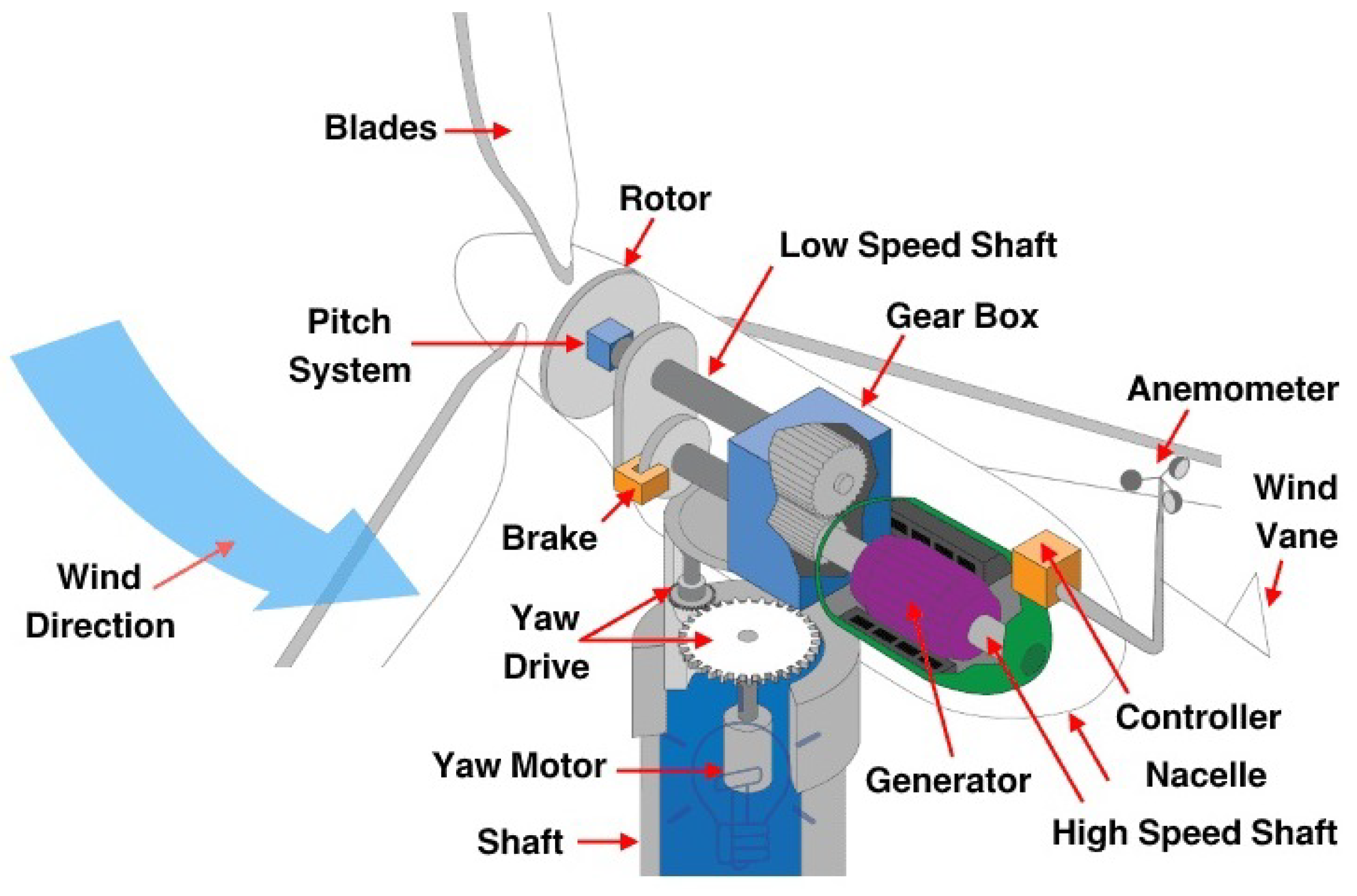
Figure 1. The general schematic of a wind turbine [44].
Energies 17 03963 g001
Figure 2. Two-mass model of wind turbine [45].
Energies 17 03963 g002
Figure 3. Block diagram of a pitch actuator model.
Energies 17 03963 g003
Figure 4. The wind turbine hydraulic blade pitch system’s structure.
Energies 17 03963 g004
Figure 5. Step response for various faults in the pitch system.
Energies 17 03963 g005
Figure 6. Rotor speed error RMS that is subject to various faults and wind conditions.
Energies 17 03963 g006
Figure 7. Generator power P g (MW).
Energies 17 03963 g007
Figure 8. Rotor speed ω r (rad/s).
Energies 17 03963 g008
Figure 9. Generator speed ω g (rad/s).
Energies 17 03963 g009
Figure 10. Pitch angle β .
Energies 17 03963 g010
Figure 11. Residual for the fault effect.
Energies 17 03963 g011
Figure 12. Sliding surface S (t).
Energies 17 03963 g012
Table 1. The case study wind turbine’s parameters [50].
ParametersDefinitionUnitValue
R T W ratingMW5
J g generator inertiaKg·m261
J r rotor inertiaKg·m2 3.26 × 10 5
ρ air densityKg/m31.542
Rrotor radiusm40
N g gearbox ratio-78.569
T g rated generator torqueN·m7683.5
ω r * rated rotor speedrad/s1.4824
K d t drive-train spring factorN·m/rad 6.5 × 10 8
B d t drive-train damping factorN·m·s/rad 9.5 × 10 6
P a pitch angle limitdeg−1 to 90
P r pitch rate limitdeg/s−10 to +10
Table 2. Effects of various faults on the dynamics of the pitch system [48].
Faults ζ ω n
Healthy0.612.12
High air content in oil0.456.37
Pump wear0.758.82
Pressure drop0.94.24
Table 3. Computational properties of FAST.
Properties L 1 Adaptive- SMC Adaptive- SMC Adaptive Control
Real-Time29.4136.5894.17
CPU-Time28.6635.7492.63
Ratio-Time5.0754.1671.379
Disclaimer/Publisher’s Note: The statements, opinions and data contained in all publications are solely those of the individual author(s) and contributor(s) and not of MDPI and/or the editor(s). MDPI and/or the editor(s) disclaim responsibility for any injury to people or property resulting from any ideas, methods, instructions or products referred to in the content.