Article

Control Optimization for Heat Source Temperature of Vacuum Belt Drying System Based on Fuzzy Control and Integral Control

1
College of Mechanical Engineering, Tianjin University of Science and Technology, Tianjin 300222, China
2
Technical Institute of Physics and Chemistry, Chinese Academy of Sciences, Beijing 100190, China
*
Authors to whom correspondence should be addressed.
Energies 2024, 17(15), 3824; https://doi.org/10.3390/en17153824
Submission received: 7 July 2024 / Revised: 20 July 2024 / Accepted: 22 July 2024 / Published: 2 August 2024
(This article belongs to the Section J1: Heat and Mass Transfer)

Abstract

:
The heating source temperature of the vacuum belt system (VBD) is an important factor affecting the drying rate and the material quality. However, it has problems with large fluctuation, instability, and hysteresis due to interference from various factors, which increases the drying time and energy consumption. To address these issues, this study proposes fuzzy control and integral control synergistic (FCICS) control to realize temperature regulation of the VBD system, enhancing the performance and stability of the heating source. Simulations were conducted in Simulink, and an experimental verification was carried out based on the constructed experimental system. The results show that the FCICS control outperforms the conventional PID control in terms of material warming rate, temperature stability, and energy consumption, and the transient and stable state performance is improved. Specifically, the material warming rate increased by 15%, temperature stability improved by 20%, and energy consumption decreased by more than 1.74% with the FCICS control strategy.

1. Introduction

Vacuum drying, known as green drying, is an effective method for retaining material quality [1]. This process takes advantage of the fact that the boiling point of water decreases with the increase of the vacuum belt, enabling moisture in the material to evaporate at a low temperature [2]. A typical representative of vacuum drying is the vacuum belt drying system (VBD), which enables uninterrupted feeding and discharging [3]. Compared with other drying methods, such as heat pump drying [4,5], microwave drying [6], and freeze drying [7], it has the characteristics of large processing capacity [8], achieving a wide range of applications.
In the content of VBD, the drying chamber is under vacuum conditions, where the ambient temperature is much lower than that of the heat source temperature, thus minimally affecting the temperature rise of the material. Meanwhile, the heat source directly heats the material through conduction. So, the heating temperature of the hot water plays a crucial role in determining the material’s drying temperature [9,10]. It is imperative to maintain the optimal heating temperature to ensure an efficient drying rate, while preserving the material’s structure of effective content in the thermal sensitive material [11]. Moreover, under vacuum conditions, the pressure and humidity remain constant; selecting appropriate operating conditions is key to minimize drying time and reduce heating energy consumption [12]. Based on the above analysis, an effective heating temperature control strategy is essential to ensure the heating temperature’s reliable operation and high efficiency under the optimum temperature to guarantee the material’s drying quality.
At present, the traditional control strategy has relied on limit control and the conventional PID control, which is the most commonly used control strategy in the drying system [13]. However, these methods are limited by the fixed value of the regulation parameters, with the problem of poor, hard real-time conditions. It is difficult to meet the dynamic changes in operating conditions and this method cannot realize precise temperature control, which affects the drying time and heating energy consumption [14].
In response to these problems, researchers have demonstrated that advanced computer technologies, such as fuzzy control [15], model prediction [16], and neural network [17], are applied to the material drying process to deal with the influence on the heating temperature fluctuations. These technologies improve the precision of temperature control and ensure the quality of materials [18,19,20,21]. To address the poor control effect and strong coupling of system parameters in vacuum drying, Zhu Guangyao et al. [22] proposed fuzzy PID control, achieving the error of heating temperature as no more than 1 °C and enhancing the quality of the dried material. For the problems of large hysteresis, nonlinearity, and poor time-varying temperature control, Guo S et al. [23] proposed a PID parameter fuzzy self-tuning control strategy to achieve fully optimized heating temperature control. The energy consumption of the equipment was reduced effectively, and the quality of the dried fruits and vegetables was improved significantly. Yang L et al. [24] designed a control system for grain drying test equipment, which combined virtual instrumentation technology and computer technology with a digital PID control algorithm for testing. The final experimental stage showed that the drying environment temperature error was less than ±1 °C.
In addition, scholars developed control strategies based on the material drying characteristics by combining control methods to achieve precise temperature control. R. Bórquez et al. [25] proposed a drying protocol based on the automatic control of temperature in response to the problem of strawberry drying temperature control, reducing the temperature fluctuation by controlling the microwave power. The energy efficiency was significantly improved to 54%, while the dried strawberries were of a high quality. Li et al. [26] used instantaneous power control technology to automatically adjust the power and product temperature, improving the color, aroma, and appearance quality of the dried materials, while maintaining energy consumption at 22 kJ/g. Additionally, Li et al. [27] proposed a control method combining variable microwave power based on predefined power curves with feedback temperature control to solve the problem of apple burning easily caused by higher heating/drying temperatures. The method achieved optimal temperature control and maintained the best appearance and taste of apples. They [28] also developed a microwave drying system that automatically adjusted power and controlled heating temperature based on the moisture ratio of apples at different stages, reducing temperature fluctuations, saving time, and lowering energy consumption. Ji et al. [29] proposed an intelligent temperature control system integrating wireless multi-point temperature and humidity acquisition, alarm display, and intelligent control through the analysis and research on the temperature control of existing ginseng processing equipment. This system can guarantee the quality of ginseng drying, improve the efficiency of ginseng drying, and reduce carbon emissions and the labor force.
Despite these advancements, the main research gaps in terms of research on using control algorithms and control strategies for the heating source in the VBD have been summarized as follows:
(1)
The classical PID controller, constrained by static parameter values, struggles to adapt to dynamic operational changes with multiple interdependent parameters, leading to imprecise temperature control that impacts both drying efficiency and energy consumption;
(2)
Advanced computer technologies require theoretical knowledge and involve complex debugging, making their practical application challenging;
(3)
Integrating the control strategy with the material drying characteristics in the VBD systems entails a prolonged time and significant investment to achieve precise temperature control.
Therefore, this paper proposes a nonlinear control strategy using the fuzzy control and integral control synergistic (FCICS) control for temperature regulation, and applies it to the VBD system. This strategy is designed to overcome the limitations of traditional control, particularly in the face of system nonlinearity and unpredictable factors such as variations in return water temperature due to changes in drying capacity. The key aspects of this research are described below:
(1)
A synergistic control structure with fuzzy control serves as the primary controller and integral control as the secondary is proposed for accurate temperature regulation, switching control modes based on temperature threshold values in the VBD system;
(2)
The robustness of the proposed control strategy is analyzed for adverse conditions such as variation in the setpoint, followability, and disturbance rejection through simulation and experimental methods;
(3)
The performance of the designed FCICS control for the drying process, in contrast to its classical PID control, is briefly analyzed.

2. Materials and Methods

2.1. VBD System Introduction and Analysis

2.1.1. The VBD System Introduction

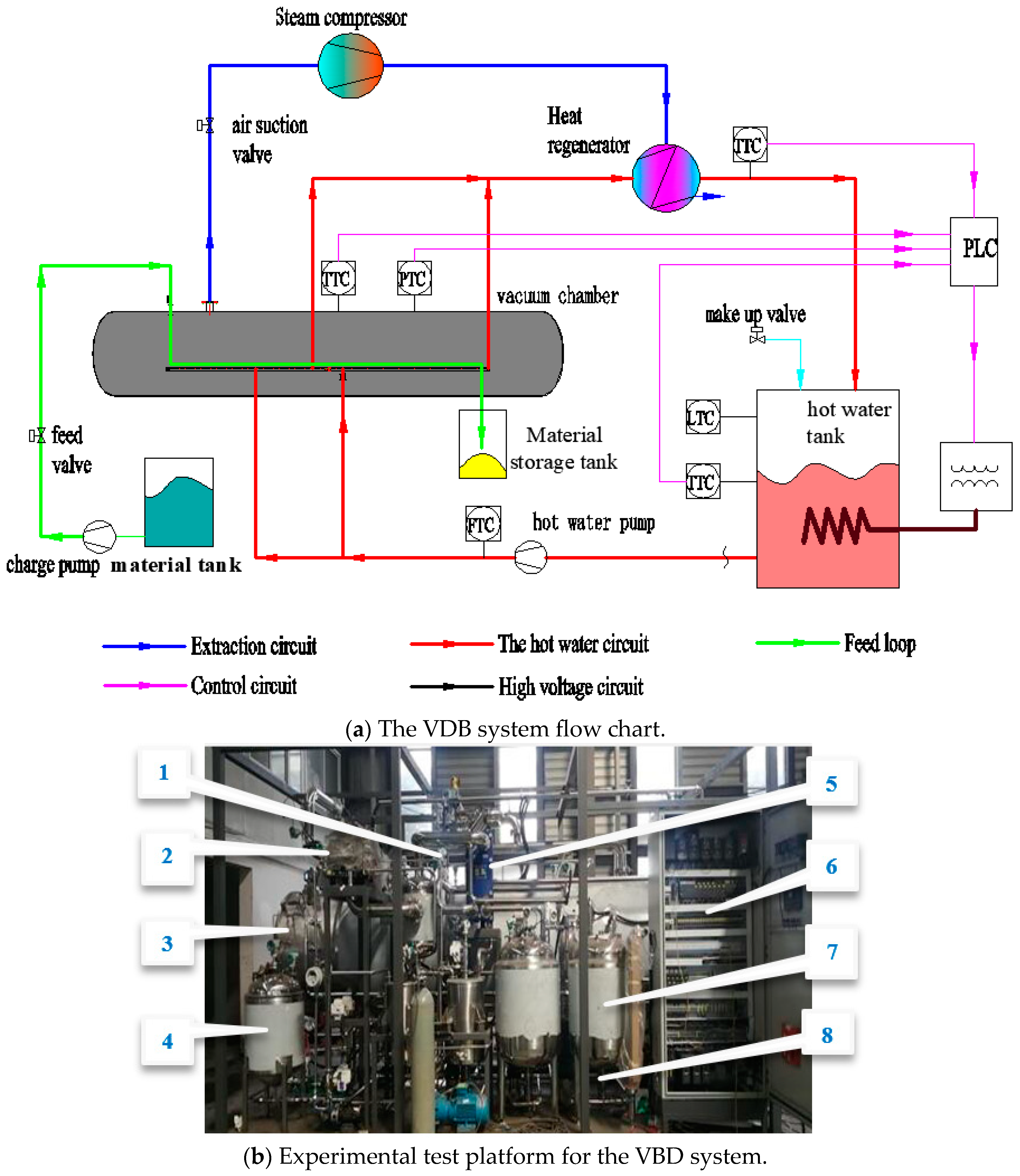
Figure 1a exhibits the flow chart of the VBD system, which comprises three distinct cycles; (1) Heating cycle system: this system utilizes water as the heat transfer medium, serving as the source of heat. The hot water pump conveys the hot water that meets a specific temperature to the heating plate in the vacuum chamber to exchange heat with the material. As the water cools, it returns to the hot water tank, relying on its flow rate, where it is reheated by electric heaters to the desired temperature. (2) Material conveying system: it plays the role of material transmission. The material in the raw material tank relies on the raw material pump to convey it to the conveyor belt on the upper layer of the heating plate in the vacuum chamber, and is heated for moisture evaporation. Once dried, the material is expelled through a discharge mechanism into a storage tank. (3) Vacuum Maintenance System: this system ensures the preservation of vacuum conditions within the chamber. The water vapor, which has become saturated due to the material’s evaporation, is continuously removed by a water vapor compressor. This vapor is then released into the atmosphere, helping to maintain a constant pressure within the vacuum chamber.
The material conveying system transports materials into the vacuum drying chamber, passing sequentially through heating zones controlled by the heating cycle system. Under vacuum conditions, the materials are heated, generating saturated water vapor, which is continuously expelled via the Vacuum Maintenance System, enabling continuous drying of the materials.
The experimental platform was established as shown in Figure 1b, and each serial number in the figure was marked as follows. 1: pressure gauge, 2: water vapor compressor, 3: vacuum chamber, 4: material tank, 5: material tank, 6: control cabinet, 7: hot water tank, and 8: hot water pump.
The control system process of the system heating cycle is as follows: the programmable logic controller (PLC) in the control cabinet receives the signal from the temperature transmitter at the hot water inlet end and converts the analog signal into a digital signal [30]. After calculating the internal control algorithm, the PLC outputs a control signal to adjust the power regulator to change the heating power in real time, ensuring that the hot water temperature is maintained at a consistent level by adjusting the heating power as needed.

2.1.2. Heat Transfer Analysis

To simplify the model, the following assumptions have been made in this paper:
(1)
The system operates in stable working conditions, with the hot water flow rate and compressor operating frequency maintained at a constant 15 L/min and 50 Hz, respectively, and the ambient temperature is set at 18 °C;
(2)
The steam outlet temperature of the drying chamber is considered to be at the saturation point;
(3)
The heat transport mechanism is heat conduction; at a steady state, the humidity remains constant.
The energy balance, where the heat released by the hot water is equal to the sum of the heat absorbed by the material and the heat loss of the system, is expressed as follows:
Q ( S ) = Q 1 ( S ) + Q 2 ( S )
Q 1 ( S ) = C P d T H dt
Q 2 ( S ) = T H T 0 R
where Q is the heat released by hot water, kJ·s−1; Q 1 ( S ) is the heat absorbed by materials, kJ·s−1; Q 2 ( S ) is the system heat loss, including the losses through the casing to the surroundings and losses in removing excess moisture from the drying chamber to the surroundings, kJ·s−1; C P is the specific heat capacity at a constant pressure of hot water, kJ·kg−1·°C−1; T H is the inlet temperature of hot water, °C; T 0 is the outlet temperature of hot water, °C; R is a constant valve; and R is the heat resistance, which represents the resistance encountered by heat during the transfer process.
After Laplace transformation, Equation (4) can be obtained:
Q ( S ) = ( C s + 1 R ) T H ( S )
Because Q ( S ) was proportional to the input signal μ ( S ) and T H ( S ) is the output signal y ( S ) , the above equation can be rewritten as:
y ( s ) u ( s ) = K R R C S + 1
The system time constant Ts was determined by the RC and the system gain coefficient Ks is kR.
It is known from the inherent properties of the hot water temperature in the system that the temperature control system has a pronounced time lag, behaving as a first-order lag system [31]. It is expressed by Equation (6).
G S = y ( s ) u ( s ) = K S T S S + 1 e t τ
where τ is the time lag coefficient.
The approximate transfer function is determined according to the Equations (7) and (8) of Colin Coon [32]. The rising curve of the temperature system measures the output response time at 0.28 times and 0.682 times the target value by a given value of electrical heating power. The value of the process transfer function is determined based on the curve corresponding to the step response obtained, and the transfer function of the controlled object is given by Equation (9):
G S = Δ out Δ i n = y ( ) y ( 0 ) Δ u
T = 1.5 ( t 0.632 t 0.28 )
G S = 0.435 59 S + 1 e 4 t
where, Δ out is the changing temperature, °C; Δ in is the varying electric heating power, KW; y ( ) is the final temperature, °C; y ( 0 ) is the initial temperature, °C; t 0.28 is the time when the output response is 0.28 times, min; and t 0.632 is the time when the output response is 0.632 times in min.

2.1.3. Data Analysis

Integral performance criteria are used to evaluate the performance differences with different control modes, including the Integral of Absolute Error (IAE), Integral of Square Error (ISE), Integral of Timed Absolute Error (ITAE), and the Integral of Time Square Error (ITSE). The formulas are given by Equations (10)–(13), respectively. Based on the data sequence collected by the system, a smaller value in these criteria indicates higher accuracy and a superior control performance of the controller [33].
IAE = 0 e ( t ) dt
ITAE = 0 e e ( t ) dt
ISE = 0 e ( t ) 2 dt
ITSE = 0 t e ( t ) 2 dt
where e ( t ) was the error between the set value and the feedback value, °C, and t was the time in min.

2.2. Heating Source Temperature with FCICS Control Strategy

2.2.1. Principle of FCICS Control Strategy

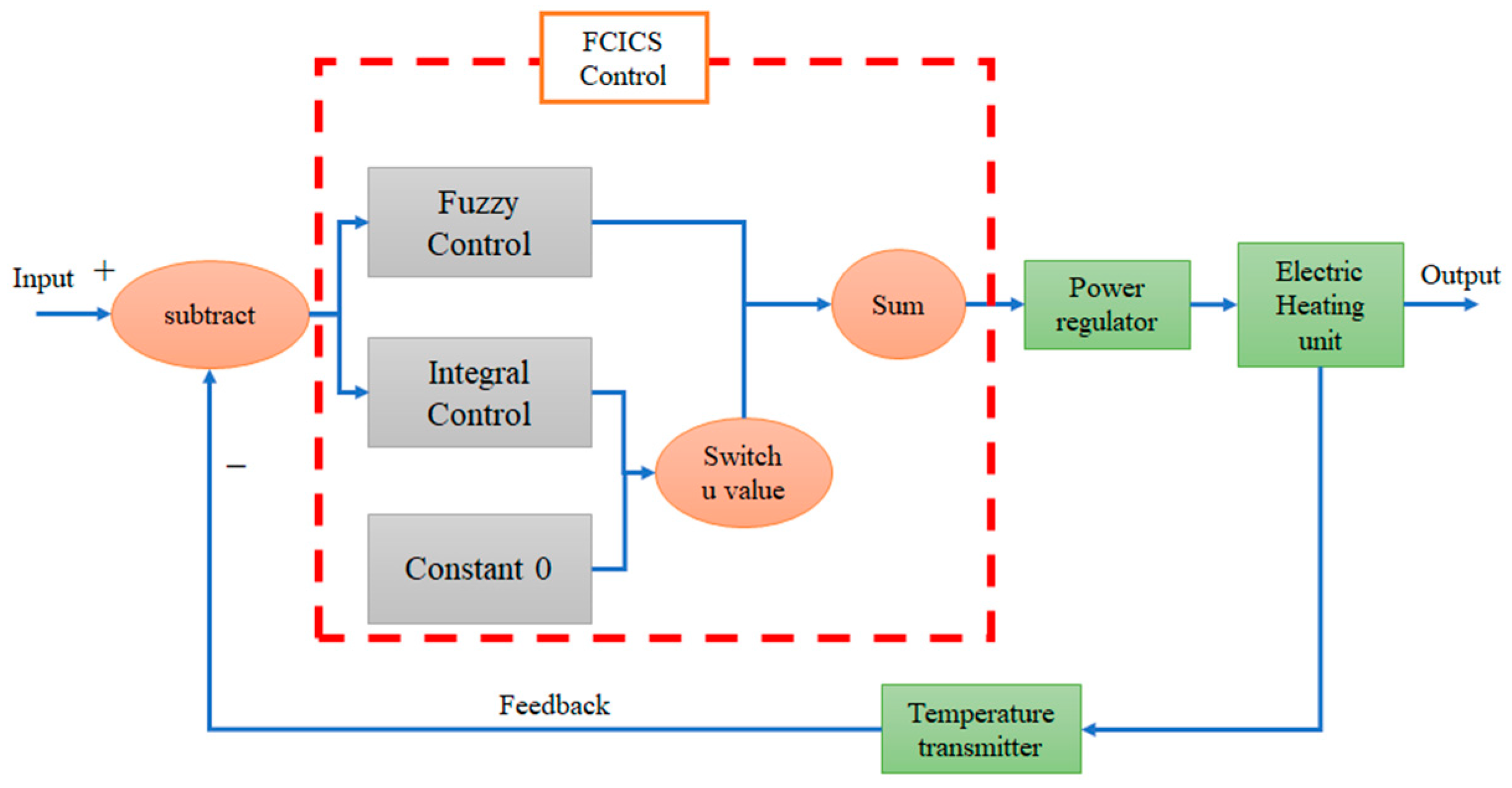
Harnessing the robustness of fuzzy control and the steady-state error reduction capability of integral control, a controller with fuzzy control and integral control synergistically (FCICS) regulating is designed at different stages.
The temperature control strategy for this controller, which combines fuzzy and integral control, is depicted in Figure 2. The switch module evaluates the difference range. If the difference between the target value and the feedback value exceeds the threshold u, the fuzzy control component is activated first, rapidly driving the heating temperature towards the set point. When the difference falls below the threshold u, the system is deemed to be nearing a stable state. At this state, integral control and fuzzy control work together to fine-tune the heating temperature, ensuring it remains close to the target value. In the event of external environmental interference affecting the control signal, fuzzy control and integral control collaborate to swiftly re-establish the stable state.

2.2.2. Fuzzy Control Design

The fuzzy controller utilizes the temperature error e (the difference between the set value of temperature and the output of the process) and the temperature derivative of the error ec as input variables, with the electric heating power serving as the output variable, forming a dual-input and single-output fuzzy controller.
Considering the desired control accuracy with ±0.5 °C at a steady state, the linguistic values for both the input and output variables are categorized into seven levels: {NB, NM, NS, O, PS, PN, and PB}, which correspond to {negative large, negative middle, negative small, zero, positive small, positive middle, and positive big}.
The Gaussian membership function is advantageous due to its smooth and continuous nature, allowing for an accurate representation of fuzzy sets with varying degrees of membership. So, the Gaussian membership function is selected for the membership function with Equation (14).
μ b = e ( x c ) 2 2 σ 2
Table 1 contains the rule base for controlling the heating temperature. These parameters specifically depend on the designer’s knowledge and experience. As the focus of this paper is on FCICS design, the rule-based design approach will not be discussed.
The Mamdani fuzzy system is selected for the fuzzy inference system and fuzzy decision making is completed using the minimum method to realize the fuzzy intersection operator and the maximum method to realize the fuzzy operator. The defuzzification process utilizes the center of gravity method, which is used to extract the fuzzy control lookup table, with the outcomes presented in Table 2. The advantage of using the center of gravity method is that it includes and utilizes all the information of the fuzzy set and adjusts it according to the degree of the membership degree. The corresponding formula is given by Equation (15):
u i = X i × μ v ( X i ) μ v ( X i )
where, μ v ( X i ) and X i are the values of the membership degree and the input variables of the affiliation function, and u i is the exact output, which represents the center of gravity point of the area enclosed by the fuzzy membership function curve and the horizontal coordinate axis.

2.2.3. Integral Control Design

The integral control eliminates the system’s static error [34]. When the error value is within the threshold u, it performs a regulatory function. The discrete mathematical relationship formula is expressed by Equation (16):
U k = K i j = 0 K e ( j ) T
where e ( j ) is the error between the set value and the feedback value, °C, and T is the time in S.

3. Results

3.1. Model Simulink of the Heating Source Temperature

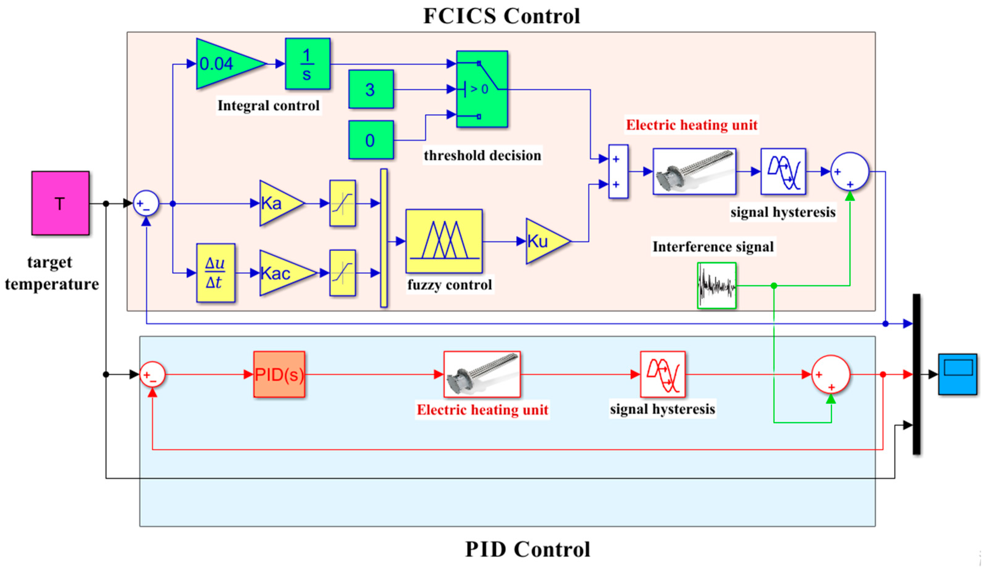
Figure 3 shows the model of the heating source temperature control system. The first control loop implements the FCICSC control, while the second control loop employs the PID control strategy. By comparing the variations in the output curves of both control loops under identical input conditions, the simulations serve to validate the stability of the FCICSC control.

3.2. Verification and Analysis of the FCICS Control

3.2.1. Disturbance of the FCICS Control

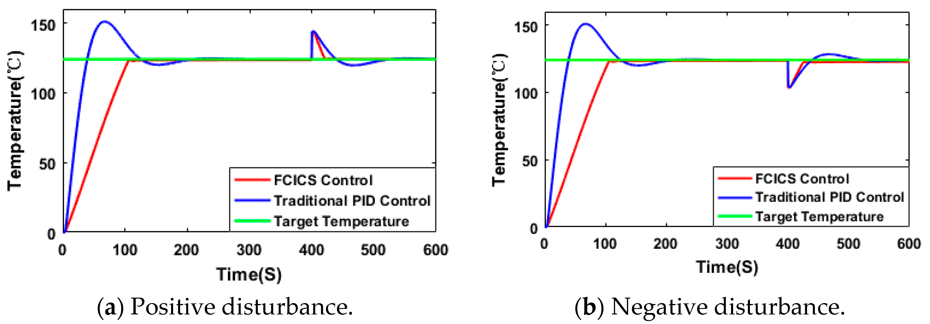
The target temperature of the material is set to be 121 °C, with the simulation duration set for 600 s. Once the system reaches a stable state, it is subjected to disturbances at the 400th second, causing deviations from the target temperature of either plus or minus 20 °C. The simulation results are shown in Figure 4.
During the temperature rise phase, the PID control reaches the target temperature faster than the arrival time of the FCICS control. However, due to the 20.9% maximum overshoot in the PID control, the system needs to stabilize at the 200th second. In contrast, the FCICS control requires only 120 s, illustrating its advantage of a shorter time required to reach the steady state and less overshooting is required. In addition, when external environmental factors perturb the hot water temperature, the FCICS control demonstrates a shorter recovery time to the target temperature compared to the PID control.

3.2.2. Following Performance of the FCICS Control

In the process of material drying, different heating temperatures are required at different stages due to changes in material composition. Therefore, the heating temperature is not a static value in the drying operation. The target temperature for the material is set as a sinusoidal signal, as defined by Equation (17). The simulation curve and the deviation curve between the target value and the output value are shown in Figure 5.
y = 10 sin 0.05 π + 124
Under the FCICS control, the feedback temperature closely follows the set temperature, with the difference between them approaching 0. This provides a strong tracking capability, meeting the temperature requirements during the material drying process. On the contrary, the feedback temperature of the PID control is always difficult to follow the target temperature, with the difference between them ranging from −5 to 5, exhibiting an obvious hysteresis.
Based on the above analysis, the FCICS control has followed the target value compared to the PID control. The improved followability of the temperature control system is suitable for the VBD’s process requirement of varying the temperature.
From the analysis presented, it is evident that the FCICS control outperforms the PID control in terms of following the target value. The enhanced followability of the temperature control system is well suited to meet the process requirements of Variable Belt Drying (VBD), which involves adjusting temperatures dynamically.

3.2.3. The Anti-Jamming Ability of the FCICS Control

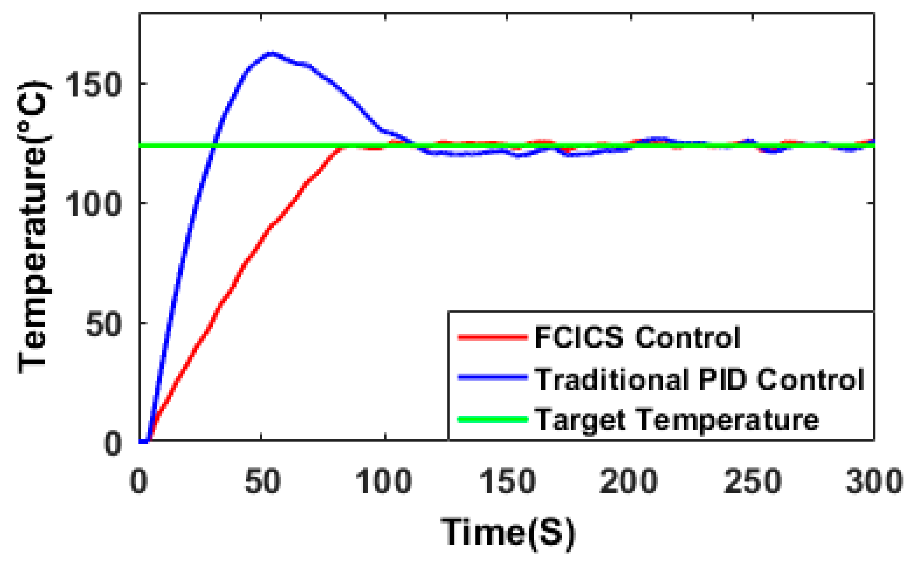
The controller is disturbed by noise signals during operation, which affect the normal regulation of the control system. In the scenario where the control output signal of the simulation model experiences continuous disturbance, the output curve appears curved, as depicted in Figure 6.
In the stabilization stage, when the PID control is disturbed by the noise signal, the unit step response curve exhibits significant volatility, with fluctuation ranges between −4 and 4. In contrast, the FCICS control demonstrates a more robust performance, with the feedback temperature fluctuation post-disturbance confined to a narrower range from −2 to 2, which is half of that of the PID control. It shows that the FCICSC approach has a greater anti-jamming ability than the PID control.
In various scenarios, the FCICS consistently demonstrates remarkable stability and convergence, with temperature output curves smoothly transitioning and stabilizing to reach the desired target value. This consistent performance highlights the strategy’s robust stability and convergence characteristics.

3.3. Experimental Validation

The VBD system constructed in Figure 1a serves as a test platform to verify the feasibility of the practical application of the FCICS control in the VBD system. The PT100 sensors (platinum resistance thermometer sensors), MIK-P300 pressure transmitter, and SFT411 metal rotor flowmeter are employed to measure hot water temperature, vacuum pressure, and hot water flow, respectively. The PLC controller chosen for this system is the Siemens S7-200 SMART. For the drying test, the traditional Chinese medicine extract with 65% viscosity was selected as the drying material.
In accordance with the fuzzy control design principles, the fuzzy control data, as shown in Table 2, and integral control equations, in ladder diagram language, are incorporated into the PLC. As a point of comparison, PID control is also implemented. Employing the 4:1 attenuation method, the proportional, integral, and differential coefficients of PID control are set at 15, 1.2, and 0.02, respectively.

3.3.1. The Target Value Changes the Effect on the Heating Source System

The initial temperature inside the hot water tank is set at 80 °C. For the first 78 min, the hot water is heated to reach a target temperature of 90 °C. Subsequently, the target temperature for the hot water is further increased to 95 °C.
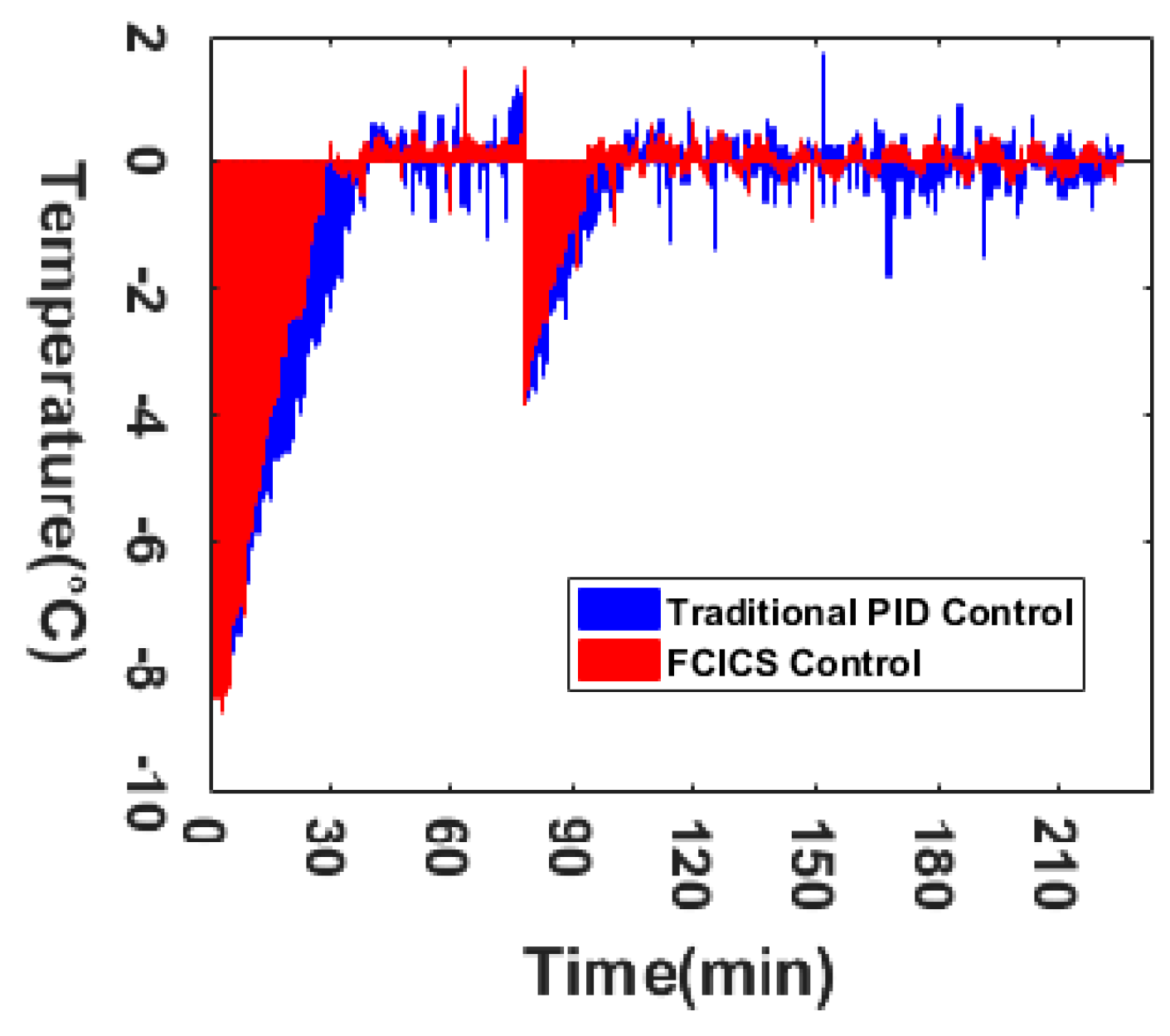
As depicted in Figure 7 and Figure 8 and Table 3, the water temperature under the FCICS control rises at a rate of 0.34 °C/min in the first pre-stage. In contrast, the average rise rate of the PID control is slightly lower at 0.27 °C/min. At a steady state, the FCICS control exhibits an improved stable state error of just 0.42 °C, which is significantly lower than the 0.73 °C stable state error associated with the PID control. Reference [27] indicates that during drying mode 2 and mode 3, the temperature deviation range in the stable phase spans from 1.06 °C to 3.06 °C, exceeding the control precision of the FCICS control. Additionally, the maximum overshoot in the FCICS is only 78.74% of that in the PID control, indicating a more precise control over the system’s response. The stabilization time for the FCICS control is notably shorter, amounting to just 75% of the stabilization time required by the PID control, signifying an enhancement in the temperature control characteristics. It is consistent with the simulation trends in Figure 4 and Figure 5. The increase in heating temperature is favorable to enhance the material drying rate, which is consistent with the study of Jingke Wu et al. (2021) [15]. Concurrently, maintaining a smaller degree of temperature fluctuation is beneficial for ensuring the drying quality of the material during the drying process.
Regarding the convergence of the FCICS control, during the initial 30 min, the temperature deviation gradually decreased from 9 °C to 0.42 °C through numerous iterations. Between the 30th and 90th minutes, the temperature deviation consistently fluctuated within the narrow range of [−0.42 °C, 0.42 °C], indicating the system’s effective regulation capability. With a subsequent 5 °C increase in the target temperature, the temperature deviation exhibited a progressive decrease. This consistent trend, reflecting the convergence observed in the preceding 90 min, highlights the system’s consistent stability across varying target temperatures, demonstrating its excellent convergence.
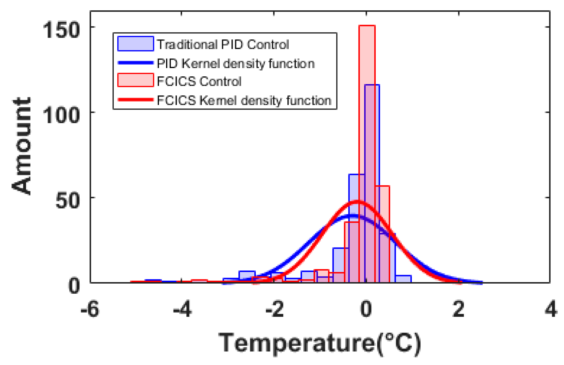
Figure 9 presents the histogram and the Gaussian kernel density function of temperature difference. The center value of the kernel density function of the FCICS control is more closely aligned with 0 °C compared to that of the PID control, which fully demonstrates that the FCICS control is more credible and accurate.
Figure 10 illustrates that during the initial 30 min of operation, the FCICS control primarily utilizes fuzzy control and operates at 100% of the full electric heating power. This is because the temperature deviation exceeds the 3 °C threshold between the feedback value and the target value. Once the temperature deviation falls below 3 °C, the integral control is integrated into the control strategy, complementing the fuzzy control to adjust the electric heating power more precisely. Then, the electric heating power is gradually decreased. Upon reaching the target temperature, the electric heating power fluctuation ranges from 6.8 kW to 9.3 kW, which is smaller than the fluctuation range between 5.3 kW and 11.2 kW for the PID control. After 78 min, the target temperature is adjusted to 95 °C. Regarding the rising temperature rate, the FCICS control exhibits an improvement of nearly 35% in the rising temperature rate compared to the PID control. Post stabilization, the FCICS control maintains a narrower fluctuation range of 7.4 kW to 10.6 kW, which is advantageous over the broader range of 6.7 kW to 12.1 kW for the PID control, facilitating more precise control over the heating temperature.
With regard to the overall heating energy consumption, the PID control strategy consumes approximately 37.95 kW over a period of 225 min. In contrast, the FCICS control system consumes an estimated 37.28 kW during the same timeframe, which reduces the overall heating energy consumption of the system by 1.77%. The decrease in energy consumption can be attributed to the FCICS control’s ability to minimize water temperature fluctuations, particularly reducing peak values. By maintaining a lower average heat transfer temperature difference with the environment, the FCICS control effectively reduces the heat losses transferred to the surroundings. Consequently, this reduction in heat loss leads to less demand for electric heating power, resulting in a decrease in energy consumption.
As seen in Table 4, with the vacuum cavity at atmospheric pressure, the water transient heating phase is from 0 to 38 min, and the water stable state phase is from 39 to 77 min. After changing the target temperature, the water transient heating stage is from 78 to 102 min, and the water stable state stage is from 103 to 225 min. The integral performance criterion coefficients of the FCICS control decrease, which reflects the excellent control performance. It shows that the FCICS control reaches the set temperature more rapidly than the PID control, exhibiting better stability and robustness.

3.3.2. Vacuum Effect on the Heating Source System

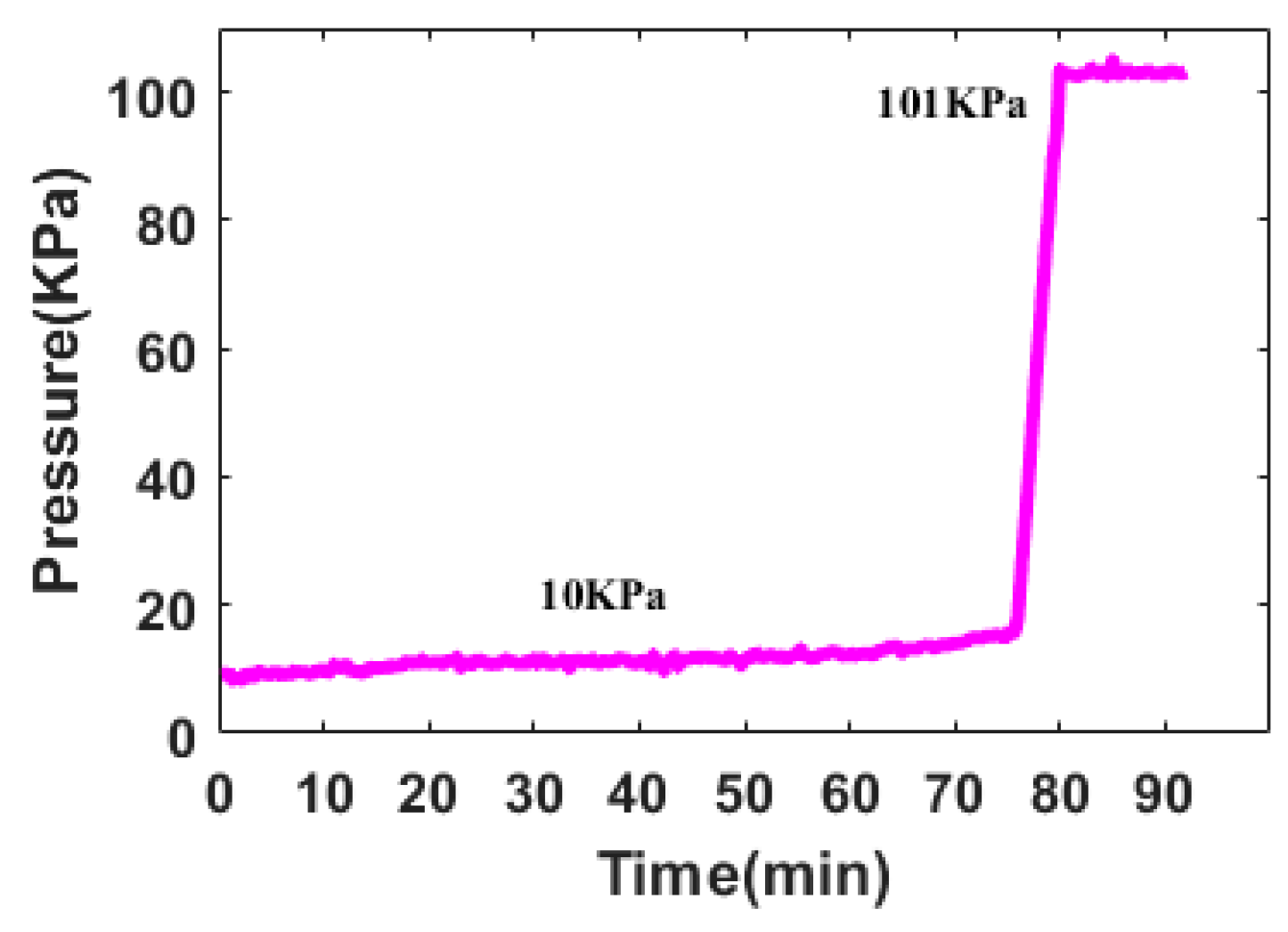
In the VBD system, the implementation of vacuum technology reduces the moisture saturation temperature within the material, accelerating the material drying rate. Therefore, the vacuum was utilized as a variable to evaluate the performance of the FCICS control. The target temperature is set at 100 °C, with the initial temperature being 95 °C from the previous experiment. The water flow rate remained constant at 20 L/min, and the pressure in the vacuum chamber was maintained at 10 KPa for the first 75 min. Subsequently, at the 75th min, the vacuum release valve was opened and the pressure of the vacuum chamber gradually increased to the ambient pressure, as depicted in Figure 11.
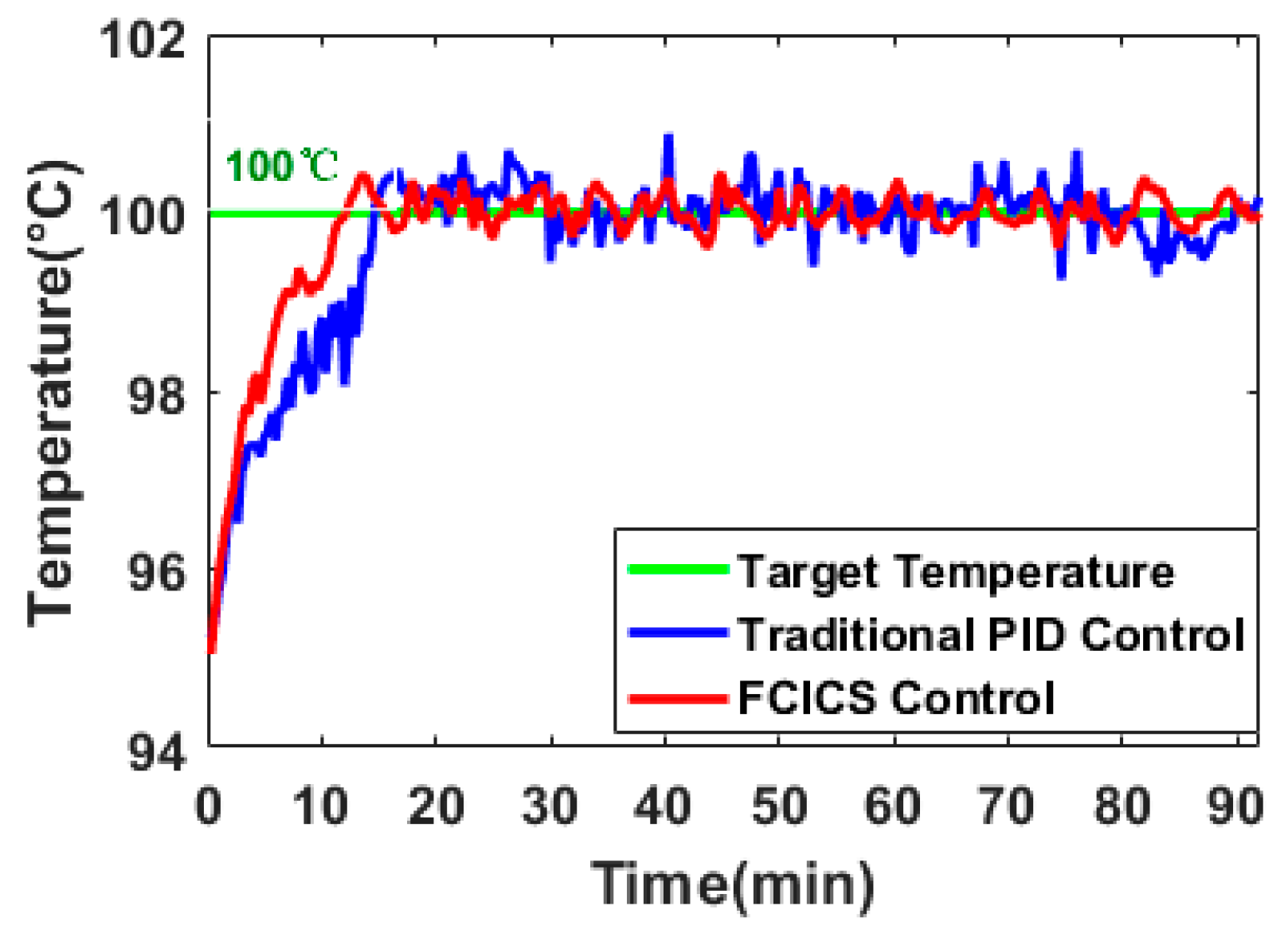
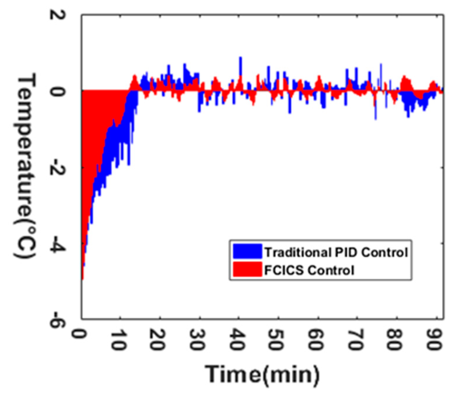
Figure 12 and Figure 13 and Table 5 show that the water temperature rises at 0.312 °C/min, approaching the target temperature swiftly with a steady-state error of 0.43 °C in the FCICS control, which is consistent with the study of Ricardo L et al. (2020) [35]. In contrast, under the PID control, the water temperature rises at 0.25 °C/min with a steady-state error of 0.71 °C. Moreover, the maximum overshoot of the FCICS control is 72.22% lower than that of the PID control, while the stabilization time of the FCICS control is 80% of that of the PID control. As analyzed above, the FCICS control exhibits significantly better temperature control characteristics. This is consistent with the simulation trend in Figure 9, where the temperature regulation reliability of the electric heating control system is improved, which is conducive to maintaining the stability of the heating temperature.
After several iterations within the initial 10 min, the temperature deviation steadily decreased from the maximum value of 5 °C to 0.43 °C. Then, the temperature deviation exhibited stable fluctuations within the narrow range of [−0.43 °C, 0.43 °C]. At the 75th minute, the fluctuations in vacuum levels within the chamber had a negligible impact on the temperature deviation. This underscores the resilience of the FCICS control against external disturbances, ensuring the consistent maintenance of temperature within the desired range and sustaining its satisfactory convergence.
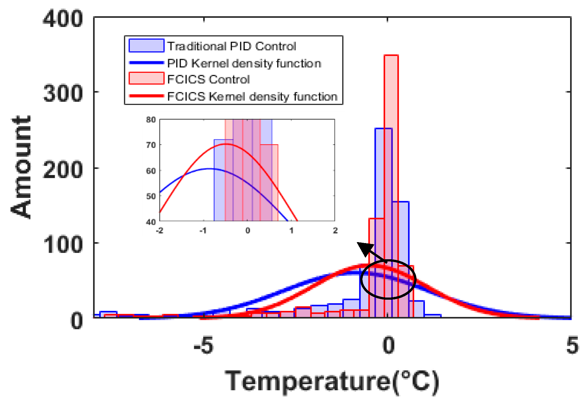
Figure 14 illustrates the temperature difference histogram and the Gaussian kernel density function. The central value of the kernel density function in the FCICS control is closer to 0 °C compared to the PID control, with a larger weight, demonstrating the greater credibility and accuracy of the FCICS control.
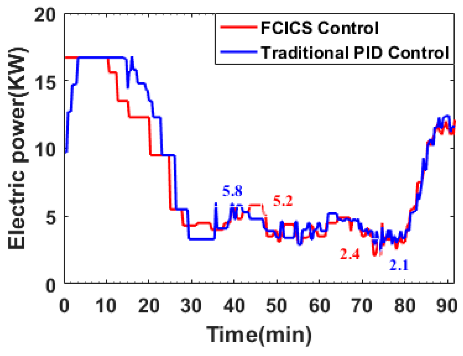
In Figure 15, the output power variation curve for both control strategies is presented. Initially, the FCICS control operates at maximum power, while the PID control gradually ramps up to maximum power. During the stabilization phase, the fluctuation range of electric heating power for the FCICS control (2.4 kW to 5.2 kW) is narrower than that of the PID control (2.1 kW to 5.8 kW). At the 78th minute, as the vacuum degree increased from 10 kPa to ambient pressure over a period of 5 min, the water temperature remained unaffected, although the electric heating power consumption of the system gradually increased. The total heating energy consumption after 92 min is approximately 11.63 kW for the FCICS control and 11.95 kW for the PID control, resulting in a 2.68% reduction in system heating energy consumption for the FCICS control. The reason is the same as the analysis in the last section. Besides that, because the target temperature is higher than the temperature set in the last section, the heat exchange with the environment is also increased, which makes the proportion of power consumption reduced by the FCICS control larger than the proportion of power consumption reduced in Section 3.3.1.
Table 6 shows the error integral criterion coefficients under different vacuum pressures. The periods are categorized as follows: 0–15 min represents the transient stage under 10 kPa vacuum pressure, 16–77 min signifies the stable stage under 10 kPa, and 78–92 min indicates the steady state at an atmospheric pressure. The integral performance criterion coefficients of the FCICS control are all reduced. It shows that the FCICS control makes the temperature control system improve the performance of suppressing errors, which avoids the overheating of materials during drying in a vacuum environment.

4. Conclusions

This study takes the VBD as the research object and proposes a combination of fuzzy control and integral control to execute different control strategies based on real-time conditions for the heating source temperature. The performance coefficient and error integration criterion serve as evaluation criteria through simulation and experimental verification. The optimized operation of the heating system enhances the stability of the heating temperature, and the following conclusions are obtained.
The FCICS control system leverages fuzzy control and integral control to perform different regulations based on real-time parameters, harnessing the robust stability of fuzzy control and the error-eliminating characteristics of integral control. It results in a 20% increase in material warming rate while ensuring that the material temperature remains close to the target temperature without surpassing it. Compared with the PID control, the FCICS control demonstrates a significant improvement, with integration performance criterion coefficients reduced by 36.8%, 71.8%, 6.6%, and 46.8%, indicating a superior control performance. This control strategy not only enhances material drying rates and quality but also reduces electric heating power consumption by over 1.74%, leading to notable economic benefits. It is very effective in controlling and optimizing the heating process of the VBD. Moreover, with only four sets of parameters, this control strategy is simpler than other complex controls, hinting at promising industrial applications. In future work, the FCICS control can be applied to other drying technologies in order to show its generalizability in real time.
Author Contributions

Conceptualization, P.X. and Z.Z.; methodology, X.L.; software, J.Y.; validation, Y.W.; data curation, J.S.; writing—original draft preparation, Y.W.; writing—review and editing, J.S.; visualization, Q.H.; supervision, J.S.; project administration, Q.H.; funding acquisition, X.L. All authors have read and agreed to the published version of the manuscript.

Funding

This research is supported by National Key Research and Development Program of China (2022YFE0127200, 2022YEF0120900, No.2022YFD2100402) and the Science, Technology & Innovation Funding Authority (STIFA) of Egypt (ID: 44205).

Data Availability Statement

Data unavailable due to privacy restrictions.

Acknowledgments

Thanks to all the participants.

Conflicts of Interest

The authors declare no conflicts of interest.

Abbreviations

NomenclatureITAEIntegral of Timed Absolute Error
cpspecific heat capacity, kJ kg−1°C−1ITSEIntegral of Time Square Error
henthalpy (kJ/kg K−1)NBnegative large
mmass flow rate (kg/s)NMnegative middle
Ttemperature (K or °C)NSnegative small
ppressure (KPa)PSpositive small
Qheat exchange power (kW)PNpositive middle
ttime (s or min)PBpositive big
Ttemperature (K)Greek symbols
Vvolume (m3)ΔDifference between before and after moments
AcronymsμDefuzzification output
VBDVacuum belt dryingσVariance
FCICSFuzzy control and integral control synergisticSubscripts
PLCProgrammable logic controllerininput
IAEIntegral of Absolute Error outoutput
ISEIntegral of Square Error isample j

References

  1. Xu, P.; Peng, X.; Yuan, T.; Yang, J.; Li, X.; Zhang, H.; Zhang, Y.; Zhang, Z.; Jia, X. Effect of vacuum drying on drying kinetics and quality of the aqueous extracts of Callicarpa nudiflora Hook. et Arn. Lebensm. Wiss. Technol. 2021, 152, 112305. [Google Scholar] [CrossRef]
  2. Mujumdar, A.S.; Wu, Z. Thermal drying technologies: New developments and future R&D potential. In Proceedings of the 5th Asia Pacific Drying Conference, Hong Kong, China, 13–15 August 2007. [Google Scholar] [CrossRef]
  3. Zhao, L.; Li, J.; Pan, Y. Application and research progress of vacuum belt dryers. Chem. Eng. 2012, 40, 25–29. [Google Scholar]
  4. Tunkal, C.; Yueksel, A.; Coskun, S. Exergy analysis of banana drying process via a closed-loop air source heat pump system. Energy Sources Part A Recovery Util. Environ. Eff. 2022, 3, 6777–6792. [Google Scholar]
  5. Redko, A.; Redko, O.; Dipippo, R. Heat pumps in the drying industry-ScienceDirect. In Low-Temperature Energy Systems with Applications of Renewable Energy; Academic Press: Cambridge, MA, USA, 2020; pp. 135–175. [Google Scholar] [CrossRef]
  6. Li, Y.; Jiang, S.; Zhu, Y.; Shi, W.; Liu, Y. Effect of different drying methods on the taste and volatile compounds, sensory characteristics of Takifugu obscurus. Food Sci. Hum. Wellness 2022, 12, 223–232. [Google Scholar] [CrossRef]
  7. Kommineni, N.; Butreddy, A.; Jyothi, V.G.S.S.; Angsantikul, P. Freeze Drying for the Preservation of Immunoengineering Products. iScience 2022, 25, 105127. [Google Scholar] [CrossRef]
  8. Bai, X. Ultrasonic Vacuum Drying of Biological Viscous Materials; Chemical Industry Press: Beijing, China, 2020. [Google Scholar]
  9. Pei, Y.; Li, Z.; Song, C.; Li, J.; Xu, W.; Zhu, G. Analysis and modeling of temperature and moisture gradient for ginger slices in hot air drying. J. Food Eng. 2022, 323, 111009. [Google Scholar] [CrossRef]
  10. Jaber, J.O. Influence of Heating Rate, Temperature, and Grain Size on Drying Behavior of the Attarat Oil Shale. Energy Sources 2008, 31, 99–107. [Google Scholar] [CrossRef]
  11. Fissore, D. On the Design of a Fuzzy Logic-Based Control System for Freeze-Drying Processes. J. Pharm. Sci. 2016, 105, 3562–3572. [Google Scholar] [CrossRef]
  12. Zhang, H.; Zhang, Z.; Tong, L.; Yuan, T.; Yang, J.; Wang, L.; Xu, P.; Wang, Y.; Yu, Z.; Zhang, J. A novel mechanical vapor compression vacuum belt drying system: Model development, experimental verification and performance prediction. Energy Convers. Manag. 2022, 269, 116108. [Google Scholar] [CrossRef]
  13. Gürel, A.E.; Ceylan, I. Thermodynamic analysis of PID temperature controlled heat pump system. Case Stud. Therm. Eng. 2014, 2, 42–49. [Google Scholar] [CrossRef]
  14. Aghbashlo, M.; Hosseinpour, S.; Mujumdar, A.S. Application of artificial neural networks (ANNs) in drying technology: A comprehensive review. Dry. Technol. 2015, 33, 1397–1462. [Google Scholar] [CrossRef]
  15. Wu, J.; Ling, C.; Chen, Y.; Li, Z.; Song, F.; Raghavan, G.; Jin, G.; Song, C. Monitoring and control of microwave drying with volatiles detection of celery stalks. Comput. Electron. Agric. 2021, 187, 106256. [Google Scholar] [CrossRef]
  16. Sheik, A.G.; Seepana, M.M.; Ambati, S.R. Supervisory control configurations design for nitrogen and phosphorus removal in wastewater treatment plants. Water Environ. Res. 2021, 93, 1289–1302. [Google Scholar] [CrossRef] [PubMed]
  17. Zhu, H.; Jin, D.; Fu, N.; Chen, X.D.; Xiao, J. Neural network modeling of the dynamic inactivation of probiotics during single droplet drying for improved cell viability. Powder Technol. 2023, 413, 118042. [Google Scholar] [CrossRef]
  18. Yang, Z.; Zhou, L.; Li, Y.; Huang, Y.; Li, A.; Long, J.; Luo, C.; Li, C. Dynamic fuzzy temperature control with quasi-Newtonian particle swarm optimization for precise air conditioning. Energy Build. 2024, 310, 114095. [Google Scholar] [CrossRef]
  19. Langner, F.; Wang, W.; Frahm, M.; Hagenmeyer, V. Model predictive control of distributed energy resources in residential buildings considering forecast uncertainties. Energy Build. 2024, 303, 113753. [Google Scholar] [CrossRef]
  20. Guo, Y.; Meng, D.; Pan, L.; Zhang, J.; Yang, S. Reliability evaluation of precision hot extrusion production line based on fuzzy analysis. Structures 2024, 64, 106553. [Google Scholar] [CrossRef]
  21. Meng, D.; Wang, H.; Yang, S.; Lv, Z.; Hu, Z.; Wang, Z. Fault analysis of wind power rolling bearing based on EMD feature extraction. CMES Comput. Model. Eng. Sci. 2022, 130, 543–558. [Google Scholar] [CrossRef]
  22. Zhu, G.; Yang, C. Design of on-line control system for rapeseed vacuum drying based on fuzzy PID. Times Agric. Mach. 2017, 44, 86–87. [Google Scholar]
  23. Guo, S.; Huang, X. PLC-based control of fruit and vegetable dryer. Food Ind. 2013, 151–153. [Google Scholar]
  24. Yang, L.; Deng, J.; Song, Y. Design of Computer Measurement and Control System of Test Device for Grain Drying Based on Virtual Instrument. In Proceedings of the 2012 Eighth International Conference on Computational Intelligence & Security, Guangzhou, China, 17–18 November 2012; pp. 177–182. [Google Scholar] [CrossRef]
  25. Bórquez, R.; Melo, D.; Saavedra, C. Microwave–vacuum drying of strawberries with automatic temperature control. Food Bioprocess Technol. 2015, 8, 266–276. [Google Scholar] [CrossRef]
  26. Li, Z.; Raghavan, G.; Wang, N.; Vigneault, C. Drying rate control in the middle stage of microwave drying. J. Food Eng. 2011, 104, 234–238. [Google Scholar] [CrossRef]
  27. Li, Z.; Raghavan, G.S.V.; Orsat, V. Temperature and power control in microwave drying. J. Food Eng. 2010, 97, 478–483. [Google Scholar] [CrossRef]
  28. Li, Z.; Raghavan, G.S.V.; Orsat, V. Optimal power control strategies in microwave drying. J. Food Eng. 2010, 99, 263–268. [Google Scholar] [CrossRef]
  29. Li, J.; Li, J.; Gu, H.; Gong, H.; Li, S. Research on Automatic Temperature Adjusting and Controlling System of Ginseng Drying. In Proceedings of the 7th International Conference on Education, Management, Information and Computer Science (ICEMC 2017), Shenyang, China, 16–18 June 2017; Atlantis Press: Amsterdam, The Netherlands, 2016; pp. 1140–1145. [Google Scholar] [CrossRef]
  30. Gao, J.Y.; Wang, J.F.; Xie, J. Application of PLC and HMI in the CO2 transcritical refrigeration experimental platform. Sci. Rep. 2022, 12, 15199. [Google Scholar] [CrossRef]
  31. Panda, R.C.; Vijayan, V.; Sujatha, V.; Deepa, P.; Manamali, D.; Mandal, A.B. Parameter estimation of integrating and time delay processes using single relay feedback test. ISA Trans. 2011, 50, 529–537. [Google Scholar] [CrossRef]
  32. Liu, J.; Shen, X.; Zhao, L. System Identification Theory and MATLAB Simulation; Publishing House of Electronics Industry: Beijing, China, 2013. [Google Scholar]
  33. Hou, C.; Lin, W.; Yang, L.; Zhang, H. Experimental performance evaluation and model-based optimal design of a mechanical vapour recompression system for radioactive wastewater treatment. Energy Convers. Manag. 2022, 252, 115087. [Google Scholar] [CrossRef]
  34. Padula, F.; Visioli, A. On the stabilizing PID controllers for integral processes. IEEE Trans. Autom. Control 2011, 57, 494–499. [Google Scholar] [CrossRef]
  35. Monteiro, R.L.; Gomide, A.I.; Link, J.V.; Carciofi, B.A.; Laurindo, J.B. Microwave vacuum drying of foods with temperature control by power modulation. Innov. Food Sci. Emerg. Technol. 2020, 65, 102473. [Google Scholar] [CrossRef]
Figure 1. VDB system physical diagram and flow chart.
Energies 17 03824 g001
Figure 2. Temperature control flow chart of FCICS control.
Energies 17 03824 g002
Figure 3. Simulation system structure diagram.
Energies 17 03824 g003
Figure 4. Disturbance response curve.
Energies 17 03824 g004
Figure 5. Variability curve of followability.
Energies 17 03824 g005
Figure 6. Output curve of fuzzy control and PID control after constant interference from outside.
Energies 17 03824 g006
Figure 7. Temperature variation curves for different target temperatures.
Energies 17 03824 g007
Figure 8. Positive and negative changes in temperature deviation for different target temperatures.
Energies 17 03824 g008
Figure 9. Histogram distribution, normal density function, and local zoom plots of temperature deviation for different target temperatures.
Energies 17 03824 g009
Figure 10. Variation curves of electric heating output power for different target temperatures.
Energies 17 03824 g010
Figure 11. Vacuum degree change curve.
Energies 17 03824 g011
Figure 12. Effect of vacuum on temperature variation in different vacuum degrees.
Energies 17 03824 g012
Figure 13. Positive and negative changes of temperature deviation in different vacuum degrees.
Energies 17 03824 g013
Figure 14. Histogram distribution and normal density function of temperature deviation in different vacuum degrees.
Energies 17 03824 g014
Figure 15. Variation curves of electric heating output power in different vacuum degrees.
Energies 17 03824 g015
Table 1. Fuzzy control rule list.
UEC
NBNMNSZOPSPMPB
ENBPBPBPBPMPMPSPS
NMPBPMPMPMPSPSNS
NSPMPSPSZONSNMNM
ZOPSPSZOZOZONSNM
PSPSPSZONSNSNMNM
PMPSNSNSNMNMNBNB
PBNSNSNMNMNBNBNB
Table 2. Fuzzy control data table.
E
−6−5−4−3−2−10123456
EC−6665.365.255.254.2744421.8310
−565.255.254.274.274.2743320.810−1
−45.365.255.254.2744432.171.180−0.8−1.83
−34.274.274.273.27333210−1−1−2
−2444322210−1−2−2−2
−143332110−1−1−2.23−3−3
0432.172210−1−2−2−2.17−3−4
1332.23110−1−1−2−3−3−3−4
222210−1−2−2−2−3−4−4−4
32110−1−2−3−3−3−3.27−4.27−4.27−4.27
41.830.810−1.18−2.17−3−4−4−4−4.27−5.25−5.25−5.36
510−0.81−2−3−3−4−4.27−4.27−4.27−5.25−5.25−6
60−1−1.83−3−4−4−4−4.27−5.35−5.21−5.36−6−6
Table 3. Comparison of main parameters.
NameCondition of Rising and Stable StageChange the Set Point Condition
Control strategyStabilization timeStability precisionMaximum overshootAdjusting timeStability precision
FCICSC29 min0.42 °C1.0 °C18min0.35 °C
PID 37 min0.73 °C1.27 °C24min0.65 °C
Table 4. Integration performance criterion for different target temperatures.
NameControl Strategy0–38 min39–77 min78–102 min103–225 min
IAEPID163.4813.9638.2632.79
FCICS132.369.7230.4224.25
ITAEPID33.2213.8854.1289.71
FCICS20.789.5442.6164.54
ISEPID941.018.9390.0917.03
FCICS791.564.4169.846.46
ITSEPID135.939.48124.0647.12
FCICS89.814.4695.1616.74
Table 5. Performance table of control parameters in different vacuum degrees.
NameCondition of Rising and Stable Stage
Control strategyStabilization timeStability precisionMaximum overshoot
FCICSC12 min0.43 °C1.17 °C
PID 15 min0.71 °C1.62 °C
Table 6. Integration performance criterion for different vacuum states.
NameControl Strategy0–15 min16–77 min78–92 min
IAEPID30.0313.992.87
FCICS21.488.832.19
ITAEPID2.569.954.07
FCICS1.476.513.06
ISEPID82.254.930.76
FCICS55.091.810.46
ITSEPID4.973.581.08
FCICS2.291.310.64
Disclaimer/Publisher’s Note: The statements, opinions and data contained in all publications are solely those of the individual author(s) and contributor(s) and not of MDPI and/or the editor(s). MDPI and/or the editor(s) disclaim responsibility for any injury to people or property resulting from any ideas, methods, instructions or products referred to in the content.