Abstract
The primary objective of this paper focuses on developing a control approach to improve the operational performance of a three-level neutral point clamped (3LNPC) shunt active power filter (SAPF) within a grid-tied PV system configuration. Indeed, this developed control approach, based on the used 3LNPC-SAPF topology, aims to ensure the seamless integration of a photovoltaic system into the three-phase four-wire grid while effectively mitigating grid harmonics, grid current unbalance, ensuring grid unit power factor by compensating the load reactive power, and allowing power sharing with the grid in case of an excess of generated power from the PV system, leading to overall high power quality at the grid side. This developed approach is based initially on the application of the four-wire instantaneous p-q theory for the identification of the reference currents that have to be injected by the 3LNPC-SAPF in the grid point of common coupling (PCC). Whereas, the 3LNPC is controlled based on using the finite control set model predictive control (FCS-MPC), which can be accomplished by determining the convenient set of switch states leading to the voltage vector, which is the most suitable to ensure the minimization of the selected cost function. Furthermore, the used topology requires a constant DC-link voltage and balanced split-capacitor voltages at the input side of the 3LNPN. Hence, the cost function is adjusted by the addition of another term with a selected weighting factor related to these voltages to ensure their precise control following the required reference values. However, due to the random changes in solar irradiance and, furthermore, to ensure efficient operation of the proposed topology, the PV system is connected to the 3LNPN-SAPF via a DC/DC boost converter to ensure the stability of the 3LNPN input voltage within the reference value, which is achieved in this paper based on the use of the maximum power point tracking (MPPT) technique. For the validation of the proposed control technique and the functionality of the used topology, a set of simulations has been presented and investigated in this paper following different irradiance profile scenarios such as a constant irradiance profile and a variables irradiance profile where the main aim is to prove the effectiveness and flexibility of the proposed approach under variable irradiance conditions. The obtained results based on the simulations carried out in this study demonstrate that the proposed control approach with the used topology under different loads such as linear, non-linear, and unbalanced can effectively reduce the harmonics, eliminating the unbalance in the currents and compensating for the reactive component contained in the grid side. The obtained results prove also that the proposed control ensures a consistent flow of power based on the sharing principle between the grid and the PV system as well as enabling the efficient satisfaction of the load demand. It can be said that the proposal presented in this paper has been proven to have many dominant features such as the ability to accurately estimate the power sharing between the grid and the PV system for ensuring the harmonics elimination, the reactive power compensation, and the elimination of the neutral current based on the zero-sequence component compensation, even under variable irradiance conditions. This feature makes the used topology and the developed control a valuable tool for power quality improvement and grid stability enhancement with low cost and under clean energy.
1. Introduction
In recent years, the adoption of photovoltaic systems in the grid has risen sharply due to increased interest in renewable energy. Yet, this integration poses challenges like maintaining power quality, managing harmonic distortion, and ensuring grid stability. Effectively addressing these issues is vital to smoothly integrate renewable energy sources without compromising the grid’s reliability [1,2]. Compared to standalone PV systems and as a result of the absence of storage facilities, grid-tied photovoltaic systems (GTPSs) are more economically efficient than other types of standalone PV systems [3]. In this context, among the topologies that are used most commonly based on GTPS are the single-stage and the two-stage configurations [4].
Beginning with the single-stage GTPS, they are known for their compact size, cost-effectiveness, high efficiency, and reliability. However, upon examining the two-stage GTPS, it becomes evident that despite the single-stage inverter’s positive attributes, the two-stage system offers superior performance [4]. The two-stage configuration offers notable advantages like increased efficiency, unity power factor, precise voltage tracking, and the ability to deliver top-notch three-phase AC output with minimal harmonic distortion [5]. These benefits overshadow its downsides, which include heightened complexity, higher initial investment, reduced efficiency, and a larger physical footprint. Consequently, despite the initial allure of the single-stage alternative, the advanced capabilities of the two-stage system render it a more compelling choice overall [4,6].
In a two-stage GTPS, optimizing the extraction of maximum solar power, termed as maximum power points (MPPs), is a primary performance determinant. This process can be achieved through maximum power point tracking (MPPT) algorithms and hence enhances PV panel efficiency by dynamically adjusting DC-DC power converter duty cycles between the PV source and the load [6]. During the last few years, various MPPT techniques, such as Perturb and Observe (P and O), incremental conductance, and specialized approaches like fuzzy logic and neural networks have been outlined [7,8,9,10,11,12,13]. However, the widespread adoption of P and O and incremental conductance methods is due to their simplicity, efficiency in energy conversion, and the delivery of high-quality power to the grid [6], making those approaches the favored choices in several applications [14].
The second pivotal aspect in the two-stage GTPS involves the algorithm used for the objective of controlling the DC/AC power stage, impacting conversion efficiency and the quality of power supplied to the grid. The performance criteria, tied closely to the topology and control techniques, serve as key benchmarks for system evaluation. Notably, multiple inverter topologies provide potential avenues for improving the total power that enters the grid, which will directly influence the overall performance of the GTPS and its components [15,16].
Multilevel inverters (MLIs) have emerged as an exceptionally promising configuration in power systems, presenting unique advantages. Their standout feature—producing a stepped output voltage waveform—not only achieves higher voltage levels but also closely mimics a sinusoidal pattern compared to conventional inverters [17]. The research highlighted in [17,18] has revealed that increasing the levels in these inverters significantly reduces both the quantity and amplitudes of harmonics, thereby decreasing the total harmonic distortion (THD). Moreover, MLIs exhibit remarkable versatility in operation, accommodating varying switching frequencies—both higher and lower. This flexibility serves a pivotal role in curtailing power losses, ultimately enhancing the overall efficiency of the system. This advantage has sparked significant interest among researchers, particularly in integrating MLIs into GTPS, especially in regions grappling with grid pollution. However, the escalating number of levels in MLIs comes hand in hand with heightened complexity in controlling the system. This additional complexity serves the essential purpose of achieving the aim of maintaining equilibrium between capacitor voltages between the two split DC capacitors and effectively managing the complicated switch processes that are inherent in these inverters [4]. Consequently, researchers in the MLIs domain are grappling with the challenge of devising topologies that strike a balance. Their aim is to leverage an optimal number of components, ensuring both cost-effectiveness and high efficiency [18]. This quest for optimization is why the widespread adoption of MLIs predominantly revolves around three-level (3L) inverters. Achieving this delicate equilibrium becomes pivotal in driving the design choices within this field [4]. However, the proliferation of power converters in renewable energy systems is causing grid distortions that surpass established harmonic standards, resulting in compromised power quality, potential damage to consumer loads, and escalated power losses within the network [19]. Adding to this, non-linear loads, which include diode rectifiers, exacerbate the situation by introducing harmonics and reducing the power factor [4]. These fluctuations, compounded by varying load demands, significantly deteriorate power quality throughout the grid. The interplay of varying load demands contributes to the emergence of an unbalanced three-phase grid system, characterized by discrepancies in voltage or current amplitudes or phases. Factors such as single-phase loading, imbalanced loads, and incorporation from single-phase renewable power resources within the grid can instigate this imbalance [20]. Consequently, this mismatch can intensify line power losses, induce system instability, and elevate neutral voltage levels, substantially impacting overall grid performance [21].
Addressing the challenges posed by unbalanced nonlinear loads (UNLL) requires vigilant monitoring, load rebalancing, and often substantial infrastructure upgrades to establish a stable, efficient, and dependable power distribution network. In addition, the incorporation of active power filters, also known as APFs, plays a crucial part in the power system. The injection of compensatory currents through the point of common connection between the source and the load allows us to efficiently reduce the harmonic currents and contributes to the process of load rebalancing. In addition, APFs serve as a crucial means to interface photovoltaic systems (PVSs) with the power grid, significantly enhancing their efficiency when integrated via single-phase or three-phase multi-level inverters (3L-MIs) [4]. Consequently, combining PVs with an APF presents a more practical solution for applications within the distributed power generation system (DPGS) [4].
Research in the domain of active power filters (APFs) has primarily revolved around improving the performance of three-phase two-level (2L) inverters. Extensive exploration of control strategies has occurred, categorized into hysteresis current control and nonlinear control methods. Hysteresis-based techniques, including those utilizing PQ theory [22,23,24], adaptive fuzzy controllers based on modified-SRF methods [25], space vector modulation [26], rectifier boost techniques [27], digital-based neural networks [28], and self-tuning filters [29], have been thoroughly investigated. Similarly, control techniques are not linear and depend upon Lyapunov theory and the PQ concept [30]. Backstepping techniques [31] and FIR prediction with feedback linearization [32] have gained attention despite their intended improvements in power quality; these approaches possess limitations. Hysteresis control methods often result in increased switching frequency [22,29], reduced robustness against parameter variations, and challenges in mitigating harmonic distortions. Conversely, nonlinear control methods, while they are promising, present implementation challenges due to computational complexity, sensitivity to model inaccuracies, and stability concerns across varying operating conditions [30,31,32]. Ongoing research endeavors strive to address these limitations, aiming to establish more robust and efficient control strategies for APFs.
In recent years, FCS-MPC has emerged as an enticing solution for governing power converters and drives. Leveraging advanced microprocessors, FCS-MPC orchestrates efficient control strategies by predicting a system’s future behavior using mathematical models. It adeptly selects optimal control actions, boasting a unique capability to amalgamate diverse objectives, constraints, and nonlinearities within a singular comprehensive cost function. This finesse renders MPC ideal for meticulously managing converter variables such as current, voltage, and power, achieving precision through meticulous optimization [33]. It has been proven that employing FCS-MPC can accomplish simultaneous management of a three-phase two-level inverter-based active power filter and the integration of a two-stage photovoltaic system with the grid [34]. The primary goal is to minimize the disparity between reference and forecasted APF current values, prompting the utilization of the FCS-MPC method. This approach makes it possible to gain indirect control over the active power filtering system that is based on a three-phase inverter with two levels, which eventually makes it easier to integrate into the power grid without interruption [35].
To date, only a few studies, such as the work presented in [4], have been conducted. This study introduces novel methods in multilevel topology and FCS-MPC techniques, proposing a three-level NPC inverter-based APF. Its objectives include reducing the current distortion, compensating the reactive power, and injecting active power generated by a single-stage photovoltaic system into the grid. However, it has a limitation such as the non-capability of solving the problem of current unbalance under four-wire grid topologies, which implies the elimination r compensation of the zero-sequence components.
In contrast, this paper introduces a developed control approach merging FCS-MPC with the four-wire instantaneous p-q theory. It focuses on regulating a three-level npc converter-based parallel APF and integrating a photovoltaic system into the grid to mitigate harmonics and improve power quality. Leveraging four-wire instantaneous p-q theory aids in generating reference currents for FCS-MPC converters in three-phase four-wire systems. Its robustness lies in its accurate power estimation, harmonic compensation, neutral current management, and consideration of zero-sequence components, hence enhancing power quality and grid stability. This approach involves injecting active power produced from a two-stage photovoltaic system into the grid while fulfilling shared load requirements.
This paper is structured as follows: after presenting the introduction, the paper is organized as follows. Section 2 focuses on the detailed presentation of the different components included within the studied topology and their modeling. At the same time, their operations related to the work presented in this paper are elucidated. It is worth mentioning that in this section, the four-wire instantaneous p-q theory is explained in detail. In Section 3, the proposed strategy of model predictive control based on the finite control set is presented where its operation mode methodology has been explained in detail and the cost function, which presents the core of this proposed control, is defined clearly. Section 4 is reserved for the simulation results carried out in this paper and their discussions and analysis. Indeed, in this part, the proposed control technique and the used topology of the 3LNPC-SAPF have been investigated under different scenarios within two profiles of solar irradiance such as a constant irradiance profile and a variable irradiance profile; at the same time, various cases of the load dynamics have been investigated, such as the reactive linear load, non-linear load, unbalanced linear, and non-linear load. This paper ends with a conclusion that summarizes the main findings of the present work and the perspectives.
2. Materials and Methods
2.1. Proposed Topology
The topology investigated in this paper is shown in Figure 1. It initially contains a photovoltaic array linked with a DC/DC Boost Converter, managed by the P and O-MPPT algorithm to ensure optimized power extraction under varying environmental conditions. This converter powers two-split DC-Link capacitors connected to the input side of a three-level NPC inverter (3LNPC), acting as the core part of the investigated shunt active power filter (SAPF). To ensure the integration of the 3LNPC inverter to the gird, coupling inductors are utilized, presenting a low-pass filter allowing the suppression of harmonics related to the switching frequency from being injected to the point of common connection (PCC) with the grid. It is important to clarify that the main role of the SAPF is to ensure three main tasks such as the elimination of the harmonics generated by the load from being circulating toward the grid, the compensation of the reactive power in the load side leading to a power unity factor in the grid side, and compensation of the load current unbalance leading to the suppression of the neutral current in the grid side. In this investigated topology, the SAPF is controlled by FCS-MPC, which is based mainly on the identification of the reference currents to be injected into the PCC using four-wire instantaneous p-q theory and the measurements of the voltages across the two split DC-Link capacitors. This combined approach aims to empower the control system to efficiently manage the 3LNPC-SAPF, hence ensuring precise control while maintaining grid performance and stability. It is worth clarifying that the investigation presented in this paper requires a specific load to be incorporated in this investigated topology, it contains a configurable three-phase load to ensure four main functionalities such as inductive balanced linear load, inductive unbalanced linear load, balanced non-linear load, and unbalanced non-linear load. On the other side, the integration of the PV array via the boost DC-DC converter is an important addition to this investigated topology, which aims to enable efficient solar power extraction across variable environment conditions. Furthermore, the developed control in this paper based on the combination of the FCS-MPC and four-wire instantaneous p-q theory seeks to ensure, besides the mitigation of the grid current harmonics, the reactive power compensation and the neutral current elimination, facilitate continuous grid power injection, and enable load power sharing between the produced power from the PV system and the existing power from the gird. Overall, the objective investigation presented in this paper is to ensure the performant operation of the 3LNPC-SAPF in improving the quality of the power in the grid side based on the aforementioned requirements, while benefiting from the available solar power to reduce the power consumption from the gird, taking into account the stability and reliability of the gird operation. Furthermore, the developed control in this paper for the overall investigated topology aims to ensure a high dynamics response of the 3LNPC-SAPF face to any changes that may occur on the load side and/or in the PV system side without affecting the power quality in the grid side, ensuring adequate power sharing to efficiently reduce the energy consumption costs. The last goals to be taken into account and that are based on the selection of using the FSC-MPC approach that is the minimization of the computational burdens, the ease of implementation, and the simplicity of including the main constraints and the objective of the control by the rational building of the cost function, which is the main core the of the used control approach.
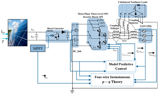
Figure 1.
Proposed configuration of the grid connected to two-stage photovoltaic systems using an active power filter (APF) with a control strategy that is based on a three-level NPC inverter.
2.2. Modeling of the Proposed Topology
This section outlines the equations employed for modeling the different components within the proposed topology such as the PV system, the boost DC-DC converter, the MPPT control approach, the three-phase three-level neutral point clamped inverter (3LNPC), the shunt active power filter based on 3LNPN (3LNPC-SAPF), and the approaches of controlling the DC-DC converter and the identification of reference current of the SAPF.
2.2.1. Modeling of PV Array
A solar cell, which is the basic unit of a PV array, operates as a semiconductor P-N junction. Indeed, different combinations of these cells form the PV array can be modeled using various circuits. The single diode is the most prevalent equivalent circuit of a PV cell, as shown in Figure 2, which illustrates the structure of the model [12].
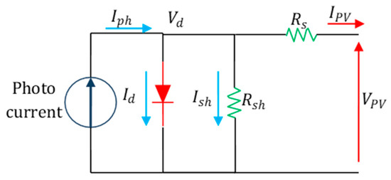
Figure 2.
Single diode model of the PV module.
The single-diode model strikes a balance between simplicity and precision. It consists of a photocurrent source connected in parallel with a nonlinear diode, a shunt resistor, and a series resistor (as shown in Figure 2). The photocurrent depends mainly on the solar irradiation and the cell’s temperature [13]. Equation (1) outline the relationship between the output current and output voltage in this model.
where denotes the current and voltage outputs of the PV module, stands for generated current, signifies the saturation diode current, represent the shunt and series resistances, n is the ideality factor of the diode, is the thermal voltage , denotes the Bolzman constant = 1.3806503 × 10⁻²³ j/k, Tc represents the temperature of solar cell, and q stands for electronic charge Equation (1) delineates the progression of the system through the short-circuit and open-circuit states, ultimately converging into a simplified expression for a single cell. This expression is extended to encompass a PV module by incorporating considerations for cells interconnected in series as well as in parallel. The resultant formula characterizes the output current of the PV module based on its voltage, the total number of cells interconnected into series (, and the number of parallel connected cells () is represented as [7,8,12]
Here, presents the short-circuit current, equivalent to , when the PV cell operates under short-circuit conditions ( = 0). The open-circuit voltage () denotes the voltage across the PN diode/junction when = 0 and = . It represents the cell voltage in the absence of light and can be defined as
These equations illustrate the behavior of the PV module and its operationmode, explaining the dependence of its output current on the output, the configuration of cells in the module, and the key intrinsic parameters.
The investigation presented in this paper centers on a 65-kilowatt photovoltaic (PV) array featuring a series connection of 12 modules ( = 12) and a parallel arrangement of 18 modules ( = 18). For this study, SunPower’s SPR-305E-WHT-D PV modules have been specifically chosen and modeled within Simulink/MATLAB. Table 1 represents the parameters of the PV module, while Figure 3a,b showcases the current and power output of the P-V module versus the output voltage at various levels of solar irradiance and temperature. These representations offer insights into the module’s performance under different environmental conditions.

Table 1.
Specification of solar module SunPower’s SPR-305E-WHT-D.
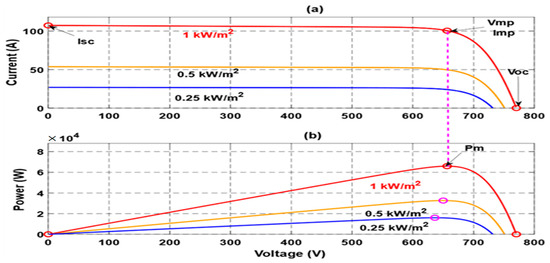
Figure 3.
PV array at 25 °C and specified irradiances (250, 500 and 1000 w/m2), (a) the out put current versu the out put voltage, (b) the output power versus the output voltage.
2.2.2. Modeling of Boost Converter
The boost converter serves to increase the low voltage generated by the PV panel to the level required by the inverter at the DC-link side, eliminating the need for a transformer in the output side of the inverter coupled to the utility grid. Its operation relies on pulse width modulation (PWM) to maximize power extraction from the PV source [6]. Components such as the switching device, inductor, capacitor, and diode work together to elevate voltage levels, as depicted in Figure 4.
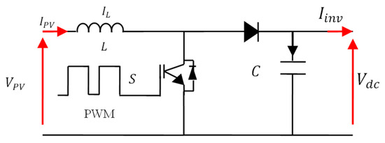
Figure 4.
Boost topology.
The converter can be represented by a distinct system of equations, referred to as an instantaneous model, where the switch is assigned a value of 1 when closed ( = 1) and a value of 0 when opened ( = 0). In this analysis, the concept of ideal switches is examined.
In these Equations (4) and (5), represents the boost input current, denotes the boost input voltage, presents the boost output voltage, stands for the inverter input current, represents the boost inductance, and denotes the boost capacitance. For a continuous current conduction, the relationship between the PV array output voltage () and the boost converter output voltage () is
The inductance value usually depends on the application required. However, it is possible to estimate this value directly and without a data sheet using the following equation:
Thus, the value of the ripple current of the inductor can be estimated as
where is a percentage of 20% to 40% of the maximum output current generated by the photovoltaic generator , signifies the switching frequency, stands for the desired DC bus output voltage, represents Boost inductance, and denotes the boost input voltage.
The DC bus capacitor can be sized according to the following equation
where presents the amplitude of the voltage ripple, which is equal to 10% of the peak grid voltage , denotes the nominal power of the PV module, stands for the frequency pulsation of the generated sine wave, and represents the average voltage across the capacitor, which is equal to
2.2.3. Modeling of MPPT Control Using the P and O Method
The widely used Perturb and Observe algorithm, as depicted in the flowchart in Figure 5, operates through a continuous cycle of observation and adjustment to reach the maximum power point (MPP). This iterative process involves comparing power and voltages at different time intervals ( and ), forecasting the path toward the MPP. A slight voltage adjustment modifies the solar panel’s power output; if the change is positive, the algorithm maintains the voltage adjustment direction. Conversely, a negative change in power signifies a deviation from the MPP, prompting a reduction in perturbation to steer closer to the optimal point [8].
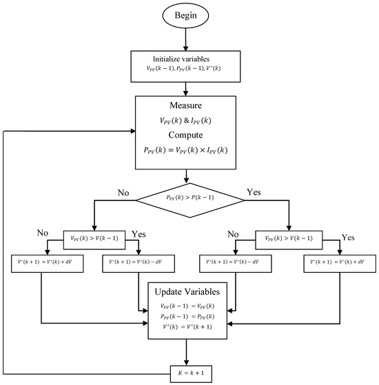
Figure 5.
Flowchart of the P and O algorithm.
The flowchart in Figure 5 involves the actual and previous values of PV panel voltage, current, and power, denoted as , , , , and , respectively. The output voltage perturbation is represented by and is an updated value employed for tracking the optimal voltage of the PV panel.
2.2.4. Modeling of Three-Level NPC Inverter
Figure 6 shows the three-level NPC multilevel converter, a variant of diode-clamped converters, which generates three-phase output voltages () at , 0, and levels, respectively. This is achieved by controlled switches with that manipulate the DC bus to the AC output. “” is the switch sequence in a leg and “” is the leg sequence. Two DC sources ( and capacitors) create the DC bus with a neutral point “z”, employing clamping diodes reach the at medium voltage level.
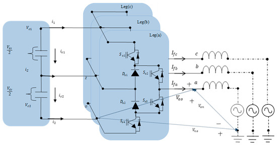
Figure 6.
Three-level NPC multilevel converter power circuit.
For bidirectional current flow, each switch pairs with an antiparallel diode. Switching states are constrained to to prevent improper converter operation. During normal functioning, commutation causes the passage of electric current across the neutral point “Z”, affecting the DC bus capacitor balance, hence necessitating a specialized modulation algorithm for voltage balance. This topology, compared to the 2L-, accommodates higher power and voltage ranges. The AC output voltage can be significantly increased using semiconductors with equal voltage ratios, as the switching identifies just half of the DC bus . It is important to note that the state where Sa1 equals 1 and equals 0 is prohibited in this converter. The other phase functions are in a similar manner. The clamping diodes operate exclusively when equals 0 and equals 1. Additionally, the voltage across every regulated semiconductors (Vce: the voltage from the collector to the emitter) remains fixed at either 0 or regardless of the switching state.
The output voltage of the inverter can be expressed as follows:
From Equation (11), the AC voltages at the inverter output at step time may be represented as
The expressions providing an insight into the charging and discharging of the capacitors and of the DC bus rely directly on the state of switching and the outputs of currents AC and can be expressed as follows:
whereas, the differential equations that are responsible for regulating the dynamics of the capacitor voltages in the DC-link are as follows:
To estimate the derivative (), a simple forward Euler approximation method is employed. This derivative estimation is crucial for accurately determining the prediction law and forecasting the filter current in subsequent time steps .
The discrete-time calculations that describe the expected values for and are
where is the sampling Time.
2.2.5. Modeling of the Active Power Filter Based on the Three-Level NPC Inverter
Figure 7 illustrates the analogous circuit of the global scheme, which consists of a shunt active power filter (SAPF) that is connected in parallel with an unbalanced non-linear load (UNLL) and the grid representing the source of power. By employing Kirchhoff’s voltage law, the following equations are obtained:
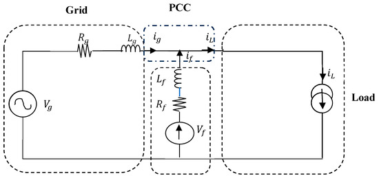
Figure 7.
An analogous circuit consisting of an APF that is linked in parallel.
The resistances of the grid and filter are considerably small, allowing us to disregard their impact. Upon subtracting Equation (20) from Equation (19), the resulting expression is as follows:
The current of the UNLL comprises two distinct components: the fundamental component represented by and the harmonic component denoted by .
whereas, based in Figure 7, the relation between the filter current, the grid current, and the load current is
By utilizing Equations (22) and (23), the following is obtained:
Therefore, it can be written that
When dealing with a slight variation in current, we can approximate Δi as approximately equal to di. Equation (25) then can be rewritten as
Upon substituting Equation (26) into Equation (21), the resultant equation can be rewritten as follows:
It is essential to use the discrete-time model in order to predict the filter current based on the actual measurements , and .
Utilizing the identical approximation method for the derivative as in Equation (16) can lead to the following equation:
The prediction law, obtained by substituting Equation (28) into Equation (27), yields the expression of the APF compensating current, as follows:
2.2.6. The Regulation of the DC-Bus and the Generation of Reference Currents of the APF
For the purpose of calculating the reference currents, the control block makes use of the instantaneous p-q theory. It is carried out based on use of the instantaneous values of grid phase voltages and load currents as input [36,37,38]. Furthermore, it incorporates the “Ploss” value obtained from the DC bus regulator block as shown in Figure 8 [39], which characterizes the fluctuation across the DC-link voltage. The principle of reference current identification is summarized in Figure 8.
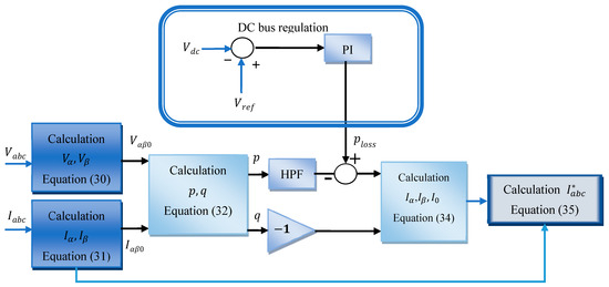
Figure 8.
The illustration of reference current calculation.
Equations (30) and (31) are utilized to compute the voltages and currents in the axis.
The load side instantaneous real power (), reactive power (), and zero sequence power () are computed according to the procedure outlined in Equation (32).
The instantaneous real and imaginary powers consist of both oscillating (AC) and average (DC) components. This allows the separation of and into two distinct parts: their average values and oscillating values.
Once the active and reactive power have been calculated, they undergo under a smoothing process to extract their oscillating terms by being passed through a low-pass filter. Hence, the reference current in frame can be calculated taking the unbalance into account, as follows:
Subsequently, these reference currents can be transformed back to the natural frame as follows:
whereas, the neutral current can be calculated by the following expression:
3. Strategy of Predictive Control Based on the Finite Control Set Model
Model predictive control (MPC) has gained more attention in the recent year as an effective control method in power electronics thanks to the important evolution of new rapid microprocessors, where this control approach has been used in many applications related to the control of complex processes, especially for multi-objective control challenges like those in multilevel inverter applications [40,41,42]. Furthermore, MPC and other new control techniques are widely used in power systems, microgrids, and integrated energy systems [43,44,45]. Typically, an MPC approach consists of three main phases: the prediction model, the cost function, and the optimization method. Each phase should be built precisely based on the type of the used converter, its physical modern operation mode, and related constraints. The MPC presents a direct control to the multilevel inverter where no modulator is needed as in the conventional control techniques such as in different PWM techniques. In this case, the input control presents a sub-set, which includes the possible switching positions of the active power electronics switching of the concerned inverter. Hence, is constrained to a finite set representing the available switch combinations. Such an approach has garnered significant attention in the power electronics community and is often referred to as the finite control set model predictive control (FCS-MPC) [40,41,42]. The control of the concerned inverter will be ensured at each step time ( is the sampling time) by a switching combination included within the set of different possible switching combinations that are defined by the set. Indeed, the selection of the element within the finite set is determined by the cost function , where corresponds to the minimal value among all possible and presents the switching combination number “” among the possible switching combination contained in . The optimal solution corresponding to will be applied to the inverter control during the time . The process of calculation is carried out at each following the process presented in Figure 9.
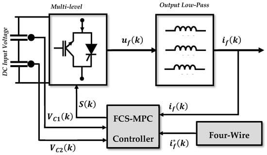
Figure 9.
Diagram and fundamental concepts of model predictive control.
In the context of employing a predictive control using a finite control set model strategy for a three-level NPC inverter functioning as an active power filter (APF). The main goal is to force the APF to reduce grid harmonic currents on the system and regulate reactive power and zero sequence currents. To fulfill these objectives and ensure proper APF operation, it is imperative to control and balance the voltages across the two DC-split capacitors. Failure to achieve this balance can lead to deviations in the voltages of the two DC-split DC-links capacitors, significantly impacting the output voltage and compromising the filtering function’s performance. Indeed, balanced capacitor voltages are essential to maintain stability and optimize the APF’s ability to handle its filtering tasks effectively.
Hence, the optimal cost function for use, is one that reduces the disparity among the expected and reference rates of the active power filter currents. Additionally, the objective is to minimize the disparity among the voltages of the two DC-split DC-link capacitors in order to maintain their consistency as well as equilibrium. The cost function proposed in this paper and which included the aforementioned constraints is expressed as follows:
where, ω represents the weighting factors that are employed in the process of balancing the voltages of the capacitors in the DC-link.
Particularly, the following procedures are included in the proposed predictive control of current:
- Acquiring of the compensatory currents from currents sensors at each sample time, ;
- Deriving the APF references currents using the instantaneous p-q theory;
- Using the derived prediction law (Equation (29)) to compute the expected value of the compensatory currents coming from the APF, , for each of the 27 possible switching states, denoted as , and subsequently determining the corresponding voltage vectors employing Equation (12);
- Assessing the cost function (Equation (37)), which aims to minimize errors between the 27 predicted filter current values (computed in the previous step) as well as the reference current that was generated. In addition to this, it lessens the amount of error that is included within the predicted voltages of the capacitors that are connected to the DC-link and while aiming for ensuring the fewest commutations possible;
- Selecting the voltage vector that minimizes the cost function as the optimum vector and using it to regulate the APF. The goal of this voltage vector selection method is to acquire the best possible performance from the APF.
The process of the application of the FCS-MPC is summarrized in Figure 10.
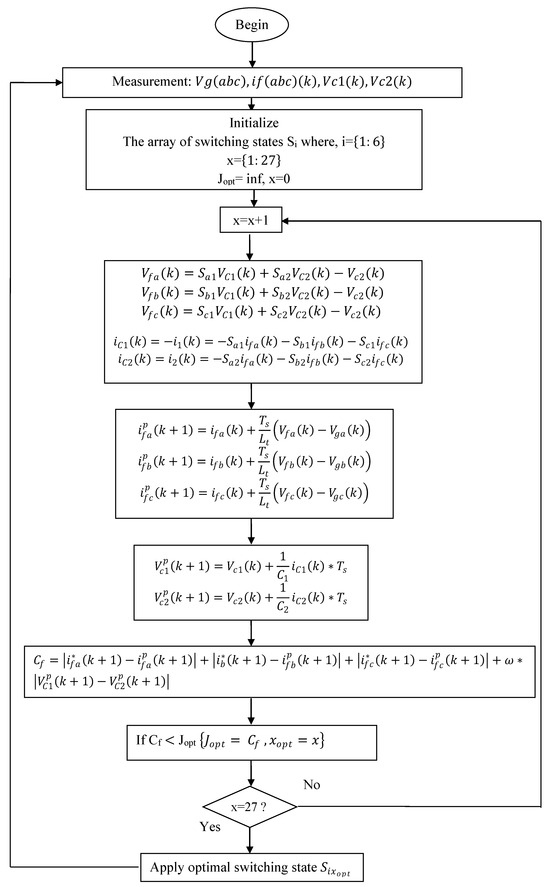
Figure 10.
The flowchart demonstrates the implementation of the suggested FSC-MPC.
4. Simulation and Discussion
For the validation of the proposed approach of finite control set model predictive control (FCS-MPC) combined with four-wire PQ theory, simulation tests were carried out under diverse scenarios, including an unbalanced linear load, balanced nonlinear load, and unbalanced nonlinear load, whereby in each scenario, two irradiance profiles have been taken into consideration: the first one is constant and the second one is variable as shown in Figure 11. Indeed, the set of the presented simulations allows the assessment of the effectiveness of the application of the proposed control on the presented topology for enhancing the power quality and grid stability under different scenarios reflecting practical cases. It is worth mentioning that the obtained results provide insights into how the system performs under various conditions based on the comparison with the theoretical aspect and other existing control techniques in the literature. The main goal is also to demonstrate and showcase the robustness of the proposed approach when integrating renewable energy sources such as the integration of the PV system into the grid while ensuring high power quality in the general consideration of four-wire applications.
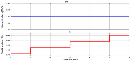
Figure 11.
Irradiance profiles. (a) profile of constant irradiance, (b) profile of variable irradiance.
It is worth clarifying that some assumptions have been taken into account within the investigated topology in this paper, with the aim of avoiding certain constraints and simplifying the modeling process such as the following ways:
- The model of the PV cell is based on a single-diode model. Indeed, its simplified equivalent circuit is represented as a current source in parallel with a diode, series resistance, and shunt resistance, as shown in Figure 2;
- The variable profile of the irradiance is chosen to have brutal variation from one step to another in order to test the high dynamic of the used control and investigate the topology itself. Indeed, practically, the irradiance profile is mostly determinist and has low dynamics; however, in this study, the depicted profile of Figure 11 is used;
- The losses in the 3LNPN and in the DC-DC converter, however its nature, are neglected;
- The power electronics switches used in both converters are supposed to be ideal. Hence, the commutation is supposed to be instantaneous under zero power losses;
- The split input capacitors at the input side of the SAPF are similar and their aging factor is neglected;
- The output filters of the SAPF, at each phase, are supposed to be identical;
- The grid utility voltage system is supposed to be balanced with sine waveform (no harmonics content);
- The aging factor of input and output capacitors of the DC-DC converter is neglected.
It is worth clarifying why the authors have selected the below scenarios for the investigation of the developed control and the investigated topology. Indeed, the main goal of this work as has been aforementioned in the previous part of the paper is the enhancement of the power quality of the grid against real constraints caused by the nature of the load such as the non-linear load and the unbalances in the load in both cases of linear and non-linear load. Under such a situation, three scenarios have been selected to be investigated in this paper to cover almost real and practical constraints. The first scenario is related to the compensations of the reactive power and the unbalances in the case of linear load to prove that the grid side current is balanced, which means no current is circulating in the neutral. The second issue is ensuring a zero shift phase between the current and the voltage in the three phases, which means a unity power factor and hence, the power from the grid is consumed in an efficient way. The second scenario is a step forward by introducing a balanced non-linear load to check the ability of the compensation of harmonics generated by the linear load. The third scenario is a step forward to check the case of an unbalanced non-linear load; in this case, three compensations are required: the harmonics, the unbalances (elimination of neutral current), and the compensation of the reactive power or the shift phase in each phase. It can be said that the three scenarios are the typical situations that can happen in the grid in practice. The other aspect of the scenarios is an investigation of the use of the PV system to contribute within the aforementioned compensation and furthermore to support the gird for powering the load. Hence, the authors proposed one practical cases with constant irradiance to check the ability of the developed control and used topology dynamics. The second one is a practical case that can be met concerning the variable irradiance. Indeed, the investigation of these two cases for the three scenarios of compensation (harmonics, reactive power, and unbalances) can converge the main objective of this study. It is important here that all the presented scenarios have shed light on the principle of power-sharing between the grid and the PV systems, which is an important issue in our world. The following six scenarios will cover all the above discussions to check the dynamics of the developed control and the used topology.
4.1. Scenario 1
4.1.1. Constant Irradiance
In this case study, the simulation is conducted under a low irradiance of 150 W/m2 where the main aim is to test the performance of the proposed approach in ensuring the injection of the desired current and power sharing through the three-level NPC inverter-based shunt APF under balanced and unbalanced three-phase linear load. Initially, the power source is operated to power a balanced load (, ). At , a switch was closed where a single phase load () is inserted in parallel to the load of the third phase “c” to introduce an unbalance in magnitude among the three phases as shown in Figure 12 and a shift phase as shown in Figure 13. Throughout the simulation, the controller’s performance was assessed in terms of its ability to maintain system stability by mitigating sources’ current unbalance, eliminating the shift phase and the neutral current. Figure 14 shows the grid voltage and the corresponding current of phase “c” where it can be seen clearly that the current maintains it at a constant equal magnitude to the other phases (155.56 A) and the shift phase between the voltage and the current is equal to zero, which implies that the gird is providing a power to the load with a unity power factor. Hence, the reactive power in the grid side is equal to zero, as shown in Figure 15, whereas the reactive power required by the load is provided by the active filter, as shown in the same figure. At the same time, it can be seen clearly that the active load power is shared between the grid and the shunt APF. On the other side, Figure 16 illustrates the current at the neutral aspect of the grid side where it is clear that the current remains equal to zero even under unbalanced current conditions. This indicates the effectiveness of the proposed controller in dealing with the current load unbalance and hence ensuring balanced grid side currents. Indeed, the ability to maintain a zero neutral current is crucial for minimizing losses and improving the overall efficiency of the system. It is worth noting that despite load unbalance, the proposed controller deals effectively with the injection of the reactive power and the required current from the shunt APF to guarantee the stable operation of the power provided to the load from the grid; less power is consumed from the grid where a part of the provided power to the load comes from the PV system through the APF.
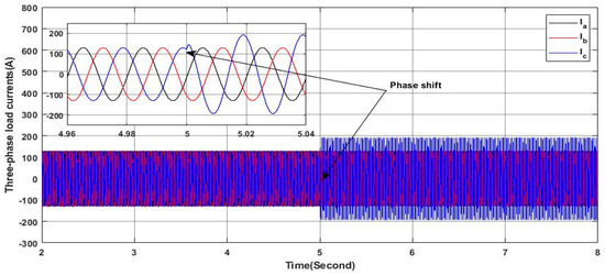
Figure 12.
Three-phase load currents.
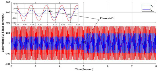
Figure 13.
Load current and voltage.
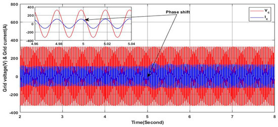
Figure 14.
Grid current and voltage.
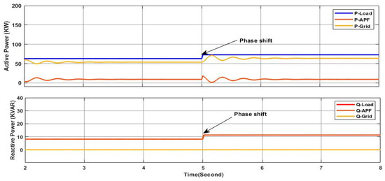
Figure 15.
Active and reactive power of load, APF, and grid.
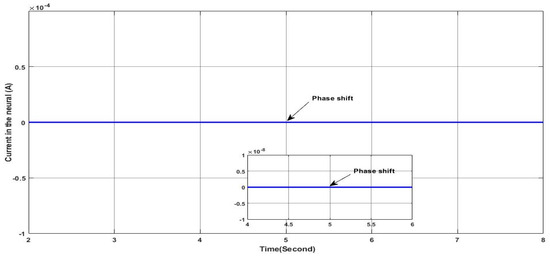
Figure 16.
Neutral current.
Figure 17 shows the DC link voltage of the active filter where it can be noted that the voltage remains nearly tracking the reference value under the aforementioned conditions. This indicates the effectiveness of the DC link-used controller. However, some oscillations are observed at the load variation instant at , which coincides with the switching between balanced and unbalanced load conditions. Despite these oscillations, the voltage promptly stabilizes and remains closer to the reference value, demonstrating the robustness of the used controller in maintaining the stable operation of the active filter under varying load conditions.
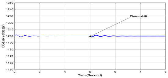
Figure 17.
DC-link voltage.
4.1.2. Variable Irradiance
In this case, the simulation is carried out with a variable solar irradiance profile as shown in Figure 11 under the same previous load profile. The irradiance values varie from 250 W/m2 to 1000 W/m2, representing a fast gradual variation in solar irradiance for testing the performance of the proposed controller in ensuring the stable mode operation of the grid side. Figure 18 presents the grid voltage and current of phase “a” where they are in phase with a zero shift phase angle despite the load unbalance and the variation in the solar irradiance, indicating stable grid side operation, as it can be confirmed from the zoomed areas in Figure 18. Figure 19 shows clearly that the grid side current remains balanced however the variation in the irradiances and the load as can be confirmed from the zoomed areas in Figure 19; this leads to zero current in the neutral, as can be observed in Figure 20. Additionally, the active power of the grid decreases by the increase in the irradiance, as shown in Figure 21, which indicates the greater contribution of the PV-APF system in sharing and providing the active power to the load; hence, less power is required from the grid to ensure that low-cost burdens are paid to the power system operator. At the same time, the reactive power provided from the grid is null, as shown in Figure 21, indicating a unit power factor at the grid side; whereas, the required reactive power from the load is fulfilled by the PV-APF system, as shown in Figure 21. These results clearly demonstrate the controller’s capability to efficiently allow power sharing between the grid and the PV-APF system in providing the load with the required power. Indeed, the PV-APF system based on the proposed controller ensures more flexibility in ensuring power sharing under variable irradiance conditions and load profile constraints such as current unbalances and low power factor, resulting in power factor unity on the grid side, with fewer power requirements and zero neutral currents. Furthermore, the DC link voltage at the input side of the APF is maintained nearly constantly with a high tracking dynamic of the reference value, as shown in Figure 22, hence ensuring efficient operation of the APF. The overall results highlight the proposed APF control and the DC link controller adaption abilities with high dynamics under severe operation conditions such as rapid irradiance variations and load profile variation to maintain stable grid side operation under balanced currents and unity power factor.
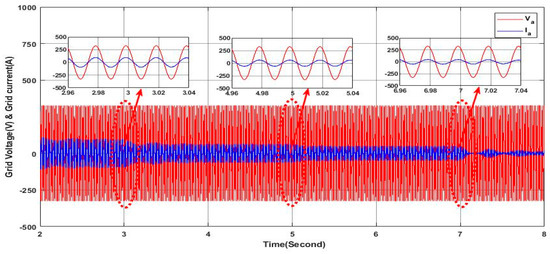
Figure 18.
Grid voltage and current.
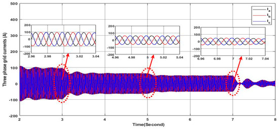
Figure 19.
Three-phase grid currents.
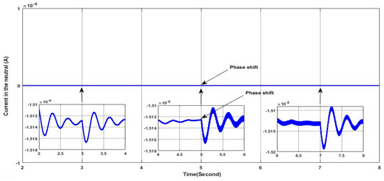
Figure 20.
Neutral current.
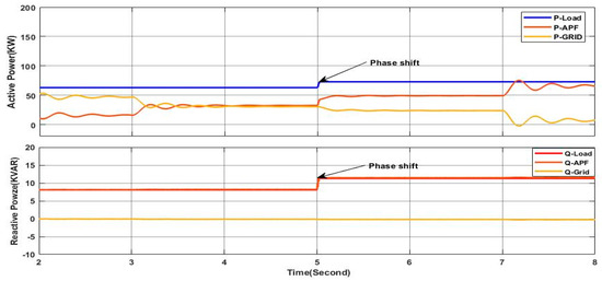
Figure 21.
Active and reactive power of load, APF, and grid.
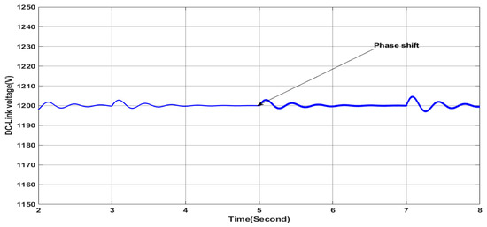
Figure 22.
DC-link voltage.
4.2. Scenario 2
4.2.1. Constant Irradiance
In this scenario, the proposed controller performances are investigated under constant solar irradiance and load transition condition where a nonlinear load is connected and the initial linear load is disconnected at the same time. Hence, initially, the system operates under a balanced linear load as in the first scenario. Whereas, at , a nonlinear load, presenting a three-phase rectifier powering an inductive load (), is connected, thus introducing the generation of the harmonics components as shown in Figure 23. It is obvious that the load current waveform undergoes distortion, deviating from its initial sinusoidal waveform characterized by a , which indicates the nonlinear behavior of the load. Furthermore, Figure 24 shows clearly that the linear load current is not in phase with the applied voltage, which means that there is reactive power required by the load. However, the grid currents maintain the sine waveform of the current, which is ensured thanks to the dynamic behavior of the proposed controller and the PV-APF system, where the harmonics of the load current have been precisely identified and eliminated from the grid current, as shown in Figure 25. Furthermore, the reactive power required by the load being provided by the PV-APF is shown in Figure 26 where the grid voltage and current of phase “a” have no shift phase, which reflects the high performances of the proposed PV-APF controller in maintaining a stable grid operation and improved power quality despite the transition condition from linear load to nonlinear load.
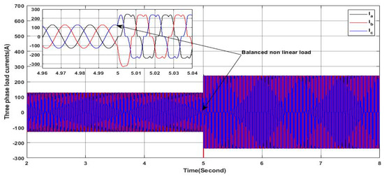
Figure 23.
Three-phase load currents.
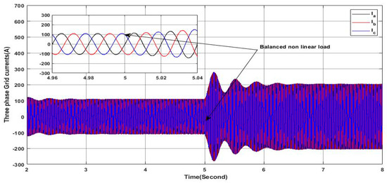
Figure 24.
Three-phase grid currents.
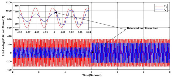
Figure 25.
Load voltage and current.
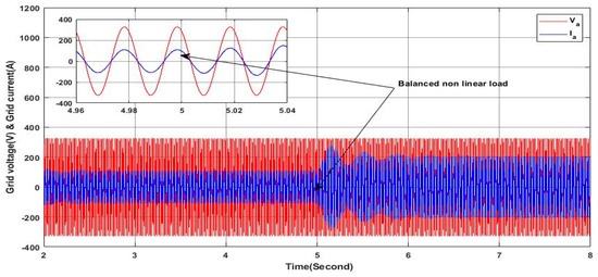
Figure 26.
Grid voltage and current.
Figure 27 presents the active and reactive power delivered by the grid, where it can be seen clearly that the reactive power remains at zero throughout the whole interval of simulation, indicating a unity power factor on the grid side, despite the reactive nature of the load, where the required reactive power is being ensured by the PV-APF system. On the other hand, the active power increases as the nonlinear load is connected, indicating that the required active power is greater than the required active power of the initial linear load where the load required active power is equal exactly to the two active powers produced by the grid and the PV-APF system, reflecting the principle of power-sharing. These results clearly prove the ability of the proposed controller and the PV-APF system to maintain the stability and the quality of the power on the grid side, which is not affected by the change in the load profile from linear to nonlinear.
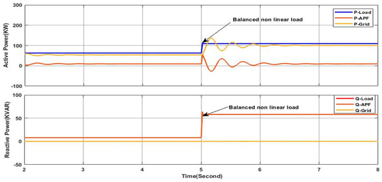
Figure 27.
Active and reactive power of load, APF, and grid.
Figure 28 depicts the DC link voltage at the input side of the active filter. It is clear that the voltage remains nearly constant and stable within reference values, even if it undergoes a short neglected oscillation during the time of transition from the linear load to the nonlinear load. This clearly proves the ability of the proposed DC-link controller to maintain the voltage tracking in the reference value, hence ensuring the high operation mode performance of the PV-APF system.
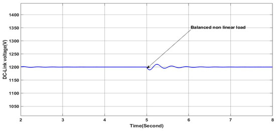
Figure 28.
DC link voltage.
4.2.2. Variable Irradiance
In this case, the same load profile as in Section 4.2.1 is considered under the variable irradiance profile, as shown in Figure 11, where the main aim is to study the dynamic performance of the proposed PV-APF controller. As shown in Figure 29, despite the fluctuations in solar irradiance availability, the proposed controller proves its effectiveness in ensuring a sine waveform of the grid side current where this can be seen clearly in the zoom areas of Figure 29. Furthermore, Figure 30 shows that the grid current in phase “a” is in phase with the corresponding voltage along the simulation interval as it can be confirmed within the zoomed areas, which means a unity power factor is ensured in the grid side without the provision of the reactive power. It is worth noting here that as the irradiance increases, the magnitude of the grid current decreases, which means there is a greater contribution of the PV-APF system in providing the load with the required active power; at the same time, the required reactive power for the load is provided totally from the PV-APF system, as shown in Figure 31. It is obvious that the active power delivered from the gird side depends only on the load requirements and the available power from the solar source where when the load active power demand increases after the transition. The active power increases slightly according to the availability of the active power from the PV-APF, which depends on the availability of the solar irradiance. In addition, when the solar radiation increases at the last step of its profile, the active power delivered from the PV-APF increases while the active power in the grid decreases as shown in Figure 31. Moreover, the DC link voltage remains nearly stable within the reference value, as shown in Figure 32, hence ensuring efficient APF operation. Based on the obtained results, it can be said that the proposed controller with the presented PV-APF systems proves high dynamics and robustness to fulfill the requirements of high power quality of the grid side by eliminating all the harmonics and the compensation of the reactive power and meeting the load power requirements even under the sudden load profile change and available solar irradiance changes.
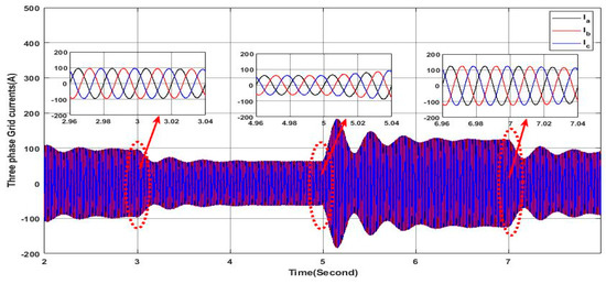
Figure 29.
Three-phase grid currents.
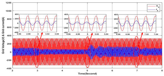
Figure 30.
Grid voltage and current.
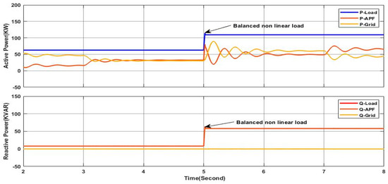
Figure 31.
Active and reactive power of load, APF, and grid.
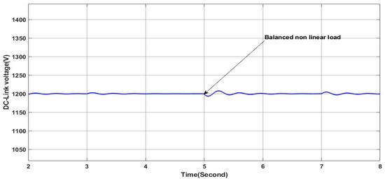
Figure 32.
DC link voltage.
4.3. Scenario 3
4.3.1. Constant Irradiance
The load profile of this scenario is similar to the precedent scenario under constant solar irradiance except that the nonlinear load connected at is an unbalanced nonlinear load, as shown in Figure 33. This unbalanced nonlinear load is composed of three single-phase rectifiers, each of which is connected between one phase and the neutral. Figure 34 proves that the grid side currents are balanced with sine waveform, which means that the PV-APF system ensures a perfect elimination of harmonics and the unbalance in the grid currents. Furthermore, the PV-APF acts precisely in compensating the reactive power, as shown in Figure 35, where it can be seen clearly that the grid side reactive power is null and the grid voltage and current of phase “a” are in phase, as shown in Figure 36. As shown in Figure 35, the reactive power required by the load is totally delivered by the PV-APF, whereas, the active power ensured by the PV-APF is limited due to the fact that the solar irradiance is limited and hence the grid is covering this gap and ensuring a perfect power sharing. It is important to note the ability of the PV-APF to ensure zero neutral currents here, reflecting the elimination of the unbalance in the grid side currents, as shown in Figure 37, where the neutral current is presented at the scale of 10−14 A. Finally, the DC-link voltage is maintained as shown in Figure 38, whereby it is constant within the reference value even under the load profile variation; this indicates the high performance and robustness of the PV-APF and the proposed control approach.
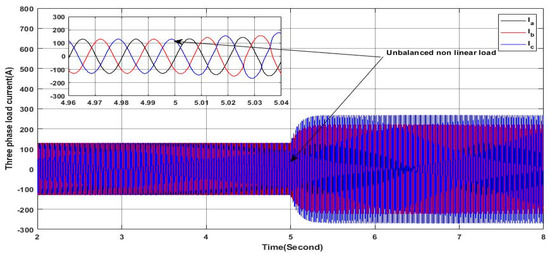
Figure 33.
Three-phase load currents.
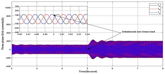
Figure 34.
Three-phase grid currents.
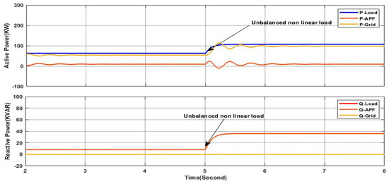
Figure 35.
Active and reactive power of load, APF, and grid.
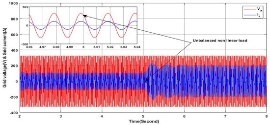
Figure 36.
Grid voltage and current.
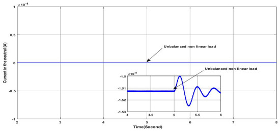
Figure 37.
Neutral current.
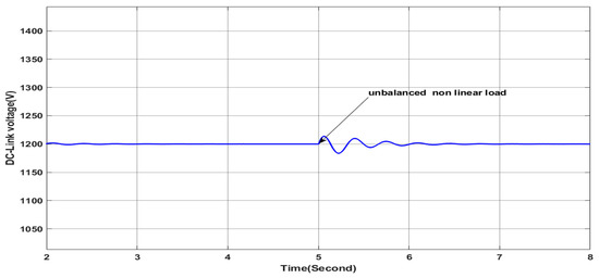
Figure 38.
DC link voltage.
4.3.2. Variable Irradiance
This scenario uses the same load profile as in the precedent scenario where the solar irradiance is variable as presented in Figure 11. Figure 39 proves the high performance of the studied PV-APF in ensuring sine waveform and unbalanced grid side current as it can be confirmed within the zoomed areas, which means that all the harmonics have been eliminated accurately. Furthermore, the reactive power is compensated, as indicated in Figure 40 where the shift phase between the grid voltage and current of phase “a” is equal to zero, as can be also confirmed within the zoomed areas; at the same time, the grid side reactive power is totally compensated, as shown in Figure 41. It is also noted that the active power of the grid decreases in the last step due to the greater contribution of the PV-APF resulting from the elevated value of the solar irradiance. It can be observed that the DC-link voltage is maintained constant following the reference value, as shown in Figure 42, which gives more ability to the PV-APF to ensure the elimination of harmonics, current unbalance, and reactive power compensation at once. Finally, Figure 43 demonstrates the high capability of the PV-APF in compensating the grid side current unbalance even under nonlinear load where the grid side neutral current is equal to zero.
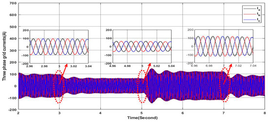
Figure 39.
Three-phase grid currents.
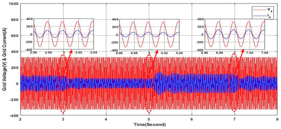
Figure 40.
Grid voltage and current.
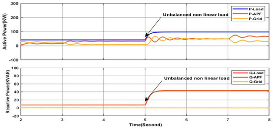
Figure 41.
Active and reactive power of load, APF, and grid.
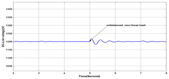
Figure 42.
DC link voltage.
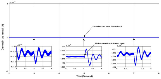
Figure 43.
Neutral current.
These observations provide evidence for the successful operation of the control system, demonstrating its ability to maintain stable grid operation under varying load conditions and solar irradiance changes. Such stability and efficiency are crucial for ensuring the reliability and optimal performance of power systems in practical applications.
Finally, the measurement of total harmonic distortion was carried out for the grid current for all the aforementioned scenarios, as presented in Table 2. It is clear that for the case of constant irradiance, the THD is the same in all scenarios, which proves the effectiveness of the developed control for ensuring a high grid current quality, even under load changes from balanced to unbalanced or from linear to nonlinear. It is worth clarifing here that the THD with linear load is 0.9% and 0.83%, following the two-step time intervals, respectively, which is due to the discrete dynamics behavior of the SAPF related to the power electronics switches, where, in practical case, the injected current by the SAPF is affected by the ripples resulting from the switching frequency. For the case of variable irradiance within the four steps as presented in the profile of the irradiance shown in Figure 11, in all cases, the THD of the grid current remains less than 2.23%, except in one case where it has a value of 5.56, which proves the effectiveness of the developed control once more. It can be noticed in Table 2 that for the second scenario and the third scenario, the THD decreases in step three (from 5 s to 7 s) and then it increases in the last step (from 7 s to 8 s); this issue also proves the flexibility of power-sharing between the grid and the PV system for the fulfillment of the load power demand whereas, when the produced power form the PV increases, the power delivered from the grid decreases, which presents a great benefit for the grid operators and the PV system user. It is obvious that as the power transferred from the PV system is less than the power transferred from the grid within the third step of irradiance change, as shown in Figure 31 and Figure 41, the grid current THD decreases due to the injection of less active power from the SAPF, where the SAPF contributes more in harmonics and reactive power compensation; hence, the discrete dynamics behavior of the SAPF is less. However, as the active power transferred from the SAPF increases compared to the one transferred from the grid as in the fourth step of irradiance change (from 7 s to 8 s), the grid current THD increases due to the discrete dynamics behavior of the SAPF, as can also be observed in the last column of Table 2.

Table 2.
Grid current THD in (%).
On the other side, it can be noticed that, for the first scenario, under variable irradiance, the measured THD in the last step from 7 s to 8 s has a value of 5.56. Indeed, this measurement is not the real THD of the grid current but it is an average value of the measured THDs for each period of 0.02 s within the interval of time of this step. This is due to the fact that the grid current has a variable magnitude due to the impact of power sharing between the grid and the PV system to satisfy the load demand. This can be clearly explained based on Figure 44. When the delivered active power by the SAPF is great than the required power of the load the active power in the grid is null; however, due to the transition within this step, there is an oscillation of the active power delivered from the SAPF near the load active power, which implies that the grid active power is very limited. With certain oscillations where the magnitude is variable, even the frequency is kept constant, which is the variable THD in each period; hence, it is represented by an average value, keeping in mind that its impact is neglected due to the less and very limited grid active power and hence limited current in the gird side.
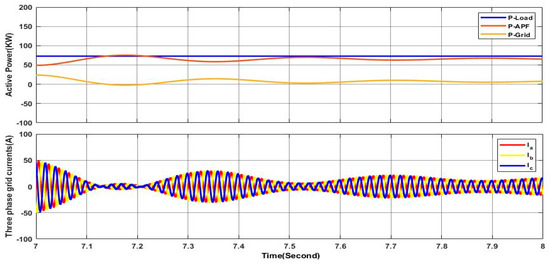
Figure 44.
Power sharing impacts on quality of grid current.
Based on the grid current THD presented in Table 2 for all the investigated cases, it can be concluded that the developed control with the 3LNPC-SAPF has fulfilled the required goals of harmonics compensation, reactive power compensation, and imbalanced load current compensation; furthermore, adequate power sharing is achieved between the PV system and the grid to satisfy the load demand under different constraints and conditions.
5. Conclusions
In this study, a comprehensive approach for integrating photovoltaic systems (PVS) through a shunt active power filter into the grid is investigated and extensively evaluated under different scenarios through simulations. The system configuration incorporates a three-level NPC inverter-based shunt active power filter (APF), which is being controlled by an advanced control strategy with the main aim of addressing key challenges in power quality, grid stability, and neutral current management.
The simulations presented in this study were carried out under two predefined operating irradiance conditions with different scenarios to demonstrate the effectiveness of the proposed control approach and the presented system topology. The first scenario is related to the sudden connection of unbalanced linear load (ULL) and the second scenario presents the connection of balanced nonlinear load (BNLL), which replaces the initial connected balance linear load to investigate the case of harmonics in the grid side current; the last scenario is dedicated to the case of unbalanced nonlinear load (UNLL) in the aim to investigate the general case of current harmonics and current unbalances elimination in the grid side. Based on the obtained results, it can be confirmed that the proposed control approach applied to the proposed topology allows for ensuring impressive performance in terms of improving the quality of the gird side current and eliminating grid side neutral current while ensuring load demand requirements based on power provision sharing between the PV system and the grid, hence ensuring the overall stability of energy supply. At the same time, the obtained results show the high dynamic of the proposed control approach, allowing the fast and accurate adjustment of the power injected by the shunt active power filter under severe variation in the solar irradiance, hence ensuring efficient power extraction from the PV system.
Furthermore, the FCS-MPC-based control strategy demonstrated exceptional accuracy in predicting and controlling filter currents, maintaining balanced DC-link capacitor voltages and effectively managing neutral current displacement. Finally, it can be said that the proposed system, based on the proposed control approach, exhibits promising capabilities in improving power quality, managing UNLL cases, and enabling efficient integration and power sharing of PV systems into the grid, hence ensuring a robust framework for reliable and high power quality in the grid side. The application of such a topology and control approach in real-time set-up applications is considered the main perspective of the work presented in this paper. Among the future works planned by the authors are three main directions. The first one is related to the implementation of the developed approach with the investigated topology in real-time, the second one is the enhancement of the developed control to meet all the real constraints of the used topology, and the third one is the improvement in the topology itself, which can be achieved through using new advanced multi-level inverters, advanced topologies of DC-DC converters, and even with the use of the single-stage topology based on advanced Z-source and qZ-source inverter topologies.
Author Contributions
Conceptualization, Z.A., A.B. and A.K.; methodology, Z.A., A.B., A.K., J.R. and M.A.; software, Z.A.; validation, Z.A., A.B. and A.K.; formal analysis, Z.A., A.B. and A.K.; investigation, Z.A.; resources, Z.A., A.B. and A.K.; data curation, Z.A.; writing—original draft preparation, Z.A., A.B., A.K., J.R. and M.A.; writing—review and editing, Z.A., A.B., A.K., J.R. and M.A.; visualization, Z.A.; supervision, A.K., J.R. and M.A.; project administration, A.K.; funding acquisition, A.K. All authors have read and agreed to the published version of the manuscript.
Funding
This research received no external funding.
Data Availability Statement
Data are included in the article.
Acknowledgments
J. Rodriguez acknowledges the support of ANID via projects FB0008, 1210208, and 1221293.
Conflicts of Interest
The authors declare no conflicts of interest.
References
- Morey, M.; Gupta, N.; Garg, M.M.; Kumar, A. A comprehensive review of grid-connected solar photovoltaic system: Architecture, control, and ancillary services. Renew. Energy Focus 2023, 45, 307–330. [Google Scholar] [CrossRef]
- Shafiullah, M.; Ahmed, S.D.; Al-Sulaiman, F.A. Grid Integration Challenges and Solution Strategies for Solar PV Systems: A Review. IEEE Access 2022, 10, 52233–52257. [Google Scholar] [CrossRef]
- Bimenyimana, S.; Asemota, G.N.O.; Ihirwe, P.J. Optimization Comparison of Stand-Alone and Grid-Tied Solar PV Systems in Rwanda. Open Access Libr. J. 2018, 5, e4603. [Google Scholar] [CrossRef]
- Lakhdari, A.; Benlahbib, B.; Abdelkrim, T. Model Predictive Control for Three-Phase Three-Level NPC Inverter Based APF Interfacing Single Stage Photovoltaic System to the Grid. J. Eur. Syst. Autom. 2022, 55, 25–34. [Google Scholar] [CrossRef]
- Ezhilvannan, P.; Krishnan, S.; Kumar, B.H.; Janardhan, K.; Ramachandran, S. Analysis of the Effectiveness of a Two-Stage Three-Phase Grid-Connected Inverter for Photovoltaic Applications. J. Sol. Energy Res. 2023, 8, 1471–1483. [Google Scholar] [CrossRef]
- Malik, N.; Ullah, S.; Khan, A.; Ullah, F. Designing and Analysis of Single Stage and Two Stage PV Inverter Connected to Weak Grid System. Int. J. Eng. Work. 2020, 7, 361–368. [Google Scholar] [CrossRef]
- Shang, L.; Guo, H.; Zhu, W. An improved MPPT control strategy based on incremental conductance algorithm. Prot. Control Mod. Power Syst. 2020, 5, 14. [Google Scholar] [CrossRef]
- Kamran, M.; Mudassar, M.; Fazal, M.R.; Asghar, M.U.; Bilal, M.; Asghar, R. Implementation of improved Perturb & Observe MPPT technique with confined search space for standalone photovoltaic system. J. King Saud Univ.—Eng. Sci. 2020, 32, 432–441. [Google Scholar] [CrossRef]
- Villegas-Mier, C.G.; Rodriguez-Resendiz, J.; Álvarez-Alvarado, J.M.; Rodriguez-Resendiz, H.; Herrera-Navarro, A.M.; Rodríguez-Abreo, O. Artificial Neural Networks in MPPT Algorithms for Optimization of Photovoltaic Power Systems: A Review. Micromachines 2021, 12, 1260. [Google Scholar] [CrossRef]
- Jately, V.; Azzopardi, B.; Joshi, J.; Venkateswaran, V.B.; Sharma, A.; Arora, S. Experimental Analysis of hill-climbing MPPT algorithms under low irradiance levels. Renew. Sustain. Energy Rev. 2021, 150, 111467. [Google Scholar] [CrossRef]
- Narwat, L.K.; Dhillon, J. Design and Operation of Fuzzy Logic Based MPPT Controller under Uncertain Condition. J. Phys. Conf. Ser. 2021, 1854, 012035. [Google Scholar] [CrossRef]
- Haq, I.U.; Khan, Q.; Ullah, S.; Khan, S.A.; Akmeliawati, R.; Khan, M.A.; Iqbal, J. Neural network-based adaptive global sliding mode MPPT controller design for stand-alone photovoltaic systems. PLoS ONE 2022, 17, e0260480. [Google Scholar] [CrossRef]
- El-Khatib, M.F.; Aner, E.A. Efficient MPPT control for a photovoltaic system using artificial neural networks. ERU Res. J. 2023, 2, 385–398. [Google Scholar] [CrossRef]
- Pakkiraiah, B.; Sukumar, G.D. Research Survey on Various MPPT Performance Issues to Improve the Solar PV System Efficiency. J. Sol. Energy 2016, 2016, 8012432. [Google Scholar] [CrossRef]
- Verbytskyi, I.; Lukianov, M.; Nassereddine, K.; Pakhaliuk, B.; Husev, O.; Strzelecki, R.M. Power Converter Solutions for Industrial PV Applications—A Review. Energies 2022, 15, 3295. [Google Scholar] [CrossRef]
- Kouro, S.; Leon, J.I.; Vinnikov, D.; Franquelo, L.G. Grid-connected photovoltaic systems: An overview of recent research and emerging PV converter technology. IEEE Ind. Electron. Mag. 2015, 9, 47–61. [Google Scholar] [CrossRef]
- Rezini, S.; Azzouz, Z.-E. Contribution of Multilevel Inverters in Improving Electrical Energy Quality: Study and Analysis. Eur. J. Electr. Eng. 2021, 23, 255–263. [Google Scholar] [CrossRef]
- Hassan, A.; Yang, X.; Chen, W.; Houran, M.A. A state of the art of the multilevel inverters with reduced count components. Electronics 2020, 9, 1924. [Google Scholar] [CrossRef]
- Rathnayake, H.; Khajeh, K.G.; Zare, F.; Sharma, R. Harmonic Analysis of Grid-tied Active Front End Inverters for the Frequency Range of 0–9 kHz in Distribution Networks:Addressing Future Regulations. In Proceedings of the 2019 IEEE International Conference on Industrial Technology (ICIT), Melbourne, VIC, Australia, 13–15 February 2019; pp. 446–451. [Google Scholar] [CrossRef]
- Alathamneh, M.; Ghanayem, H.; Yang, X.; Nelms, R.M. Three-Phase Grid-Connected Inverter Power Control under Unbalanced Grid Conditions Using a Time-Domain Symmetrical Components Extraction Method. Energies 2022, 15, 6936. [Google Scholar] [CrossRef]
- Nour, A.M.M.; Helal, A.A.; El-Saadawi, M.M.; Hatata, A.Y. Voltage imbalance mitigation in an active distribution network using decentralized current control. Prot. Control Mod. Power Syst. 2023, 8, 1–17. [Google Scholar] [CrossRef]
- Chelli, Z.; Toufouti, R.; Omeiri, A.; Saad, S. Hysteresis control for shunt active power filter under unbalanced three-phase load conditions. J. Electr. Comput. Eng. 2015, 2015, 391040. [Google Scholar] [CrossRef]
- Jauhari, M.; Ilman, A.F.; Prasetyani, L.; Dewi, T. Control Strategy for Active Power Filter Based on P-Q Theory under Non-Ideal Mains Voltages. In Proceedings of the 2020 2nd International Conference on Industrial Electrical and Electronics, ICIEE 2020, Lombok, Indonesia, 20–21 October 2020; Institute of Electrical and Electronics Engineers Inc.: Piscataway, NJ, USA, 2020; pp. 31–35. [Google Scholar] [CrossRef]
- Soomro, U.M.; Alswed, S.K.; Abdullah, M.N.B.; Radzi, N.H.B.M.; Baloch, M.H. Optimal design of a single-phase APF based on PQ theory. Int. J. Power Electron. Drive Syst. 2020, 11, 1360–1367. [Google Scholar] [CrossRef]
- Karuppanan, P. Active power filter using a novel adaptive fuzzy hysteresis current controller. J. Power Electron. 2019, 10, 315–332. [Google Scholar] [CrossRef]
- Wang, Y.L.; Guo, Q.L. Hysteresis Current Control technique based on Space Vector Modulation for Active Power Filter. Int. J. Power Electron. Drive Syst. (IJPEDS) 2011, 1, 1–6. [Google Scholar] [CrossRef]
- Baharom, R.; Yassin, I.M.; Hidayat, M.N. Active power filter with hysteresis current control loop using rectifier boost technique. Int. J. Power Electron. Drive Syst. 2020, 11, 1117–1122. [Google Scholar] [CrossRef]
- Rahim, N.A.; Radzi, M.A.M. DSP-based flexible digital hysteresis in switched capacitor active power filter. IEICE Electron. Express 2010, 7, 621–627. [Google Scholar] [CrossRef][Green Version]
- Biricik, S.; Redif, S.; Özerdem, Ö.C.; Khadem, S.K.; Basu, M. Real-time control of shunt active power filter under distorted grid voltage and unbalanced load condition using self-tuning filter. IET Power Electron. 2014, 7, 1895–1905. [Google Scholar] [CrossRef]
- Kabba, A.; El Fadil, H.; Yahya, A.; Bentalhik, I. PQ Theory of SAP Filter in Photovoltaic System Connected to Three-Phase Grid and Controlled Nonlinear. E3S Web Conf. 2022, 351, 01007. [Google Scholar] [CrossRef]
- Daou, N.; Montoya, F.G.; Ababssi, N.; Djeghader, Y. A hybrid active filter using the backstepping controller for harmonic current compensation. Symmetry 2019, 11, 1161. [Google Scholar] [CrossRef]
- Kukrer, O.; Komurcugil, H.; Guzman, R.; De Vicuna, L.G. A New Control Strategy for Three-Phase Shunt Active Power Filters Based on FIR Prediction. IEEE Trans. Ind. Electron. 2021, 68, 7702–7713. [Google Scholar] [CrossRef]
- Instituto Tecnológico de Buenos Aires; Institute of Electrical and Electronics Engineers; IEEE Industrial Electronics Society. Proceedings of the 2020 IEEE International Conference on Industrial Technology; Buenos Aires Institute of Technology (ITBA), Buenos Aires, Argentina, 26–28 February 2020; IEEE: Piscataway, NJ, USA, 2020. [Google Scholar]
- Boukezata, B.; Gaubert, J.P.; Chaoui, A.; Hachemi, M. Predictive current control in multifunctional grid connected inverter interfaced by PV system. Sol. Energy 2016, 139, 130–141. [Google Scholar] [CrossRef]
- Lakhdari, A.; Krim, F.; Borni, A. Model predictive control for an SAPF interfaced by a wind energy conversion system based on permanent magnet synchronous generator. J. Eng. Res. 2019, 7, 1–19. [Google Scholar]
- Shirkhani, M.; Tavoosi, J.; Danyali, S.; Sarvenoee, A.K.; Abdali, A.; Mohammadzadeh, A.; Zhang, C. A review on microgrid decentralized energy/voltage control structures and methods. Energy Rep. 2023, 10, 368–380. [Google Scholar] [CrossRef]
- Ju, Y.; Liu, W.; Zhang, Z.; Zhang, R. Distributed Three-Phase Power Flow for AC/DC Hybrid Networked Microgrids Considering Converter Limiting Constraints. IEEE Trans. Smart Grid 2022, 13, 1691–1708. [Google Scholar] [CrossRef]
- Zhang, J.; Liu, Y.; Zang, J.; Liu, Z.; Zhou, J.; Wang, J.; Shi, G. An Embedded DC Power Flow Controller Based on Full-Bridge Modular Multilevel Converter. IEEE Trans. Ind. Electron. 2024, 71, 2556–2566. [Google Scholar] [CrossRef]
- Sapkota, T.; Poudel, S.; Gyawali, S.; Subedi, R. Three-Phase Four-Wire Shunt Active Power Filter Using Instantaneous p-q Theory as Control Strategy; Office of KEC Research and Publications Conference (OKRP), Kathmandu Engineering College: Kalimati, Kathmandu, Nepal, 2015; Available online: https://www.researchgate.net/publication/289533758 (accessed on 12 June 2024).
- Majmunovic, B.; Dragicevic, T.; Blaabjerg, F. Multi Objective Modulated Model Predictive Control of Stand-Alone Voltage Source Converters. IEEE J. Emerg. Sel. Top. Power Electron. 2019, 8, 2559–2571. [Google Scholar] [CrossRef]
- Orłowska-Kowalska, T.; Blaabjerg, F.; Rodriguez, J. (Eds.) Advanced and Intelligent Control in Power Electronics and Drives; Springer: Cham, Switzerland, 2014; 410p, ISBN 978-3-319-03400-3. [Google Scholar]
- Rodrıguez, J.; Kazmierkowski, M.P.; Espinoza, J.; Zanchetta, P.; Abu-Rub, H.; Young, H.A.; Rojas, C.A. State of the Art of Finite Control Set Model Predictive Control in Power Electronics. IEEE Trans. Ind. Inform. 2013, 9, 1003–1016. [Google Scholar] [CrossRef]
- Zhang, J.; Liu, Y.; Zhou, J.; Zang, J.; Shi, G.; Wang, J.; Li, Y.; Yang, X. A Novel Multiport Transformer-Less Unified Power Flow Controller. IEEE Trans. Power Electron. 2024, 39, 4278–4290. [Google Scholar] [CrossRef]
- Duan, Y.; Zhao, Y.; Hu, J. An initialization-free distributed algorithm for dynamic economic dispatch problems in microgrid: Modeling, optimization and analysis. Sustain. Energy Grids Netw. 2023, 34, 101004. [Google Scholar] [CrossRef]
- Meng, Q.; Jin, X.; Luo, F.; Wang, Z.; Hussain, S. Distributionally Robust Scheduling for Benefit Allocation in Regional Integrated Energy System with Multiple Stakeholders. J. Mod. Power Syst. Clean Energy 2024, 1–12. [Google Scholar] [CrossRef]
Disclaimer/Publisher’s Note: The statements, opinions and data contained in all publications are solely those of the individual author(s) and contributor(s) and not of MDPI and/or the editor(s). MDPI and/or the editor(s) disclaim responsibility for any injury to people or property resulting from any ideas, methods, instructions or products referred to in the content. |
© 2024 by the authors. Licensee MDPI, Basel, Switzerland. This article is an open access article distributed under the terms and conditions of the Creative Commons Attribution (CC BY) license (https://creativecommons.org/licenses/by/4.0/).