1. Introduction
Over the past decade, considerable research has been devoted to the characteristics of laser surface treatment processes. However, due to the complexity of the physical processes involved in laser surface treatment, the aforementioned studies have primarily focused on the molten pool and its adjacent areas for both non-contact and contact measurements. Experimentally capturing the temperature and thermal stress distribution outside the molten pool presents significant challenges. Therefore, theoretical analysis and computational simulation play an indispensable role in the analysis of this process.
In numerous studies, when the heat source is small relative to the substrate to the extent that the shape and size of the heat source can be disregarded, the heat source can be considered a point or a line heat source. Devesse et al. [
1] derived the control equations for isothermal line growth when heating a workpiece with a steady-state or moving-point heat source. Mendez [
2] conducted a systematic scaling analysis of a steady-state point heat source on a semi-infinite solid, finding that all characteristic values related to the isotherms could be reduced to dimensionless expressions solely dependent on the Rykalin number. Heller et al. [
3] established a simplified model for the point heat source to describe the temperature field outside the melt pool during the welding process, where energy is concentrated on the top surface of a plate with finite thickness. Based on the analytical solution for the moving-point heat source by Rosenthal, Gockel et al. [
4] derived closed solutions for the temperature distribution near the free boundary and precise solutions for the free-edge effect using two closely spaced point heat sources. However, their results were applicable only to small-scale processes involving low laser power and low scanning speeds. Zhao [
5] utilized the thermal lattice Boltzmann method to conduct a two-dimensional numerical simulation of natural convection in a heated enclosed cavity, analyzing the physical principles of mass and heat transfer with different heating surface areas.
Over the last decade, the interaction between laser beams and materials, especially those beams with Gaussian profiles (TEM00 mode), has been extensively studied. Due to the complexity of the physical processes involved, several models [
6,
7] are devoted to the impact of Gaussian beam modes in thermal conduction scenarios. Cline and Anthony [
8] formulated a Gaussian heat source model based on the material’s thermal conductivity to ascertain its thermal distribution and cooling rates; the results showed the temperature distribution of a moving heat source was asymmetric relative to its direction of motion. Reséndiz-Flores et al. [
9] presented the proposition of employing the Kuhnert Finite Pointset Method (FPM) [
10] for conducting numerical simulations of heat transfer associated with a moving Gaussian thermal source during the processing of welding materials. Kar and Rath [
11] established a transient model to predict the evolution of melt pools generated by moving lasers with Gaussian and transient trapezoidal distributions in space.
Beyond the conventional models of point and line heat sources, as well as the widely utilized Gaussian heat source model for simulation purposes, the diversity in laser processing conditions across various laser machining applications has led scholars to study the thermal physical mechanisms under specific conditions by either combining existing heat source models or developing new ones. Zhou et al. [
12] employed a combined model of dual ellipsoids and a conical body as an equivalent heat source to describe the flow and heat transfer within the plasma arc welding melt pool. Flint et al. [
13] derived a semi-analytical solution for the transient heat conduction equation of a moving dual ellipsoid-conical (DEC) heat source distribution with a surface Gaussian component. Yadaiah et al. [
14] proposed a volumetric heat source model structured like an egg, which served as a heat source model for laser welding processes, and conducted a transient heat transfer analysis based on 3D finite element modeling. Velaga et al. [
15] proposed a three-dimensional finite element analysis on thin-walled cylindrical specimens of AISI 304 stainless steel, investigating the impact of the geometric parameters of a dual-ellipsoidal moving heat source during the welding process. They found that changes in the heat source’s geometrical parameters exerted minimal impact on the dimensions and shape of the melt pool and the temperature distribution without affecting the distribution of residual stresses. However, in laser surface treatment, other beam modes, like TEM01*, might offer better advantages [
16]. While point circular laser beam spots were suitable for most laser applications, there were cases where rectangular beam modes were preferred [
17]. Differing from the Gaussian laser heat source or combined Gaussian-based models predominantly used in research, the research team led by Shi [
18] developed a novel technique of annular hollow laser light powder feeding. Liu et al. [
19] investigated the effects of the hollow ratio of the hollow laser beam on the temperature distribution and cooling rate of the melt pool, and the accuracy of their numerical calculations was validated by experiments. Compared to a Gaussian heat source, this annular hollow laser heat source model can generate higher temperatures at the edges, which helps to inhibit the formation of powder adhesion and reduce the meniscus height, thereby reducing the need for post-processing steps and saving time and energy.
On the other hand, starting from the analogy between heat conduction and electrical conduction processes, Guo et al. [
20,
21] introduced physical quantity “entransy” characteristics to describe an object’s heat transfer ability and proposed the principle of minimum entransy dissipation for optimizing heat conduction processes. Xia et al. [
22] applied this principle to study a simple one-dimensional plate liquid–solid phase change process; they aimed to minimize entransy dissipation as the optimization object under the condition of a fixed total process time and derived the optimal heat transfer strategy corresponding to the phase change process. Chen et al. [
23] derived the optimal heat transfer process path with the minimum entropy generation under the general heat transfer law.
In the past few decades, extensive research has been conducted on the laser and material interaction processes, with the majority of these studies focusing on laser beams with a Gaussian profile (TEM00 mode). However, due to their high central heat flux density, Gaussian laser beams produce non-uniform temperature gradient fields on the surface of the substrate during laser surface treatment. Exceeding the material’s ultimate strength, thermal stresses can lead to substrate fracture, making Gaussian laser beams unsuitable for substrates with uniform thermal stress requirements. In contrast to traditional Gaussian beams, annular hollow laser beams significantly enhance laser energy intensity at the periphery of the spot while slightly reducing it at the center. This beam mode is an emerging technology. Several studies have explored the heat transfer mechanisms of media subjected to irradiation by moving annular hollow laser heat sources. The parameters of annular lasers impact product performance, such as surface quality and mechanical properties. To the authors’ knowledge, the effect of selecting the inner and outer radii of the annular laser on the temperature distribution of the substrate has not been studied from a heat transfer perspective.
In this study, the temperature field distribution within the computational domain was determined through numerical simulation under a constant heat flux boundary condition, the entransy dissipation extremum theory was used, and the selection of the inner and outer ring radii of the annular laser was explored. By ensuring melting, the average heat transfer temperature difference on the heating surface was minimized, thereby the thermal stress was reduced. The minimum of this indicates the minimum loss of heat transfer capacity in the process.
3. Results and Discussion
3.1. The Impact of Inner Radius of Annular Hollow Laser on Entransy Dissipation Rate
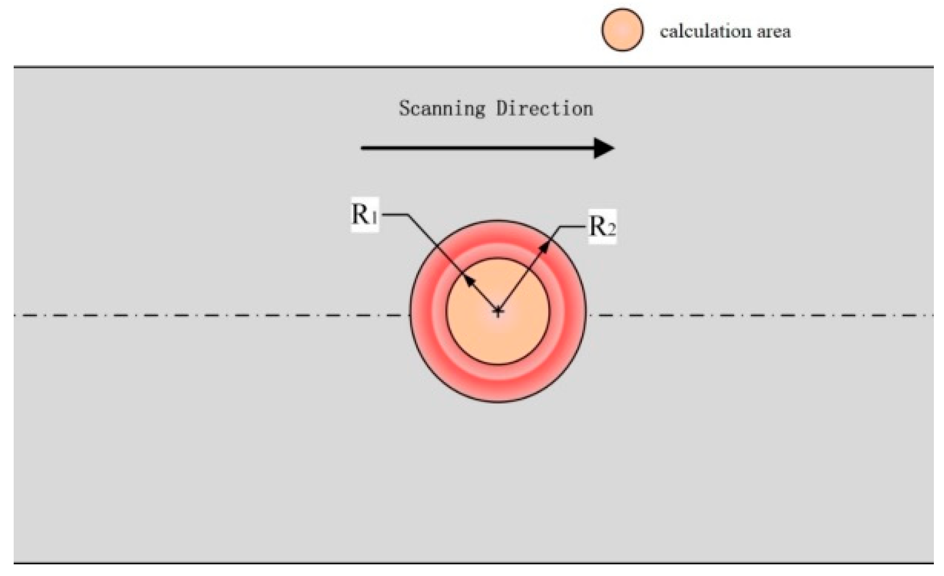
In addition to parameters such as laser power and scanning speed, the unique inner ring radius R1 and outer ring radius R2 of the annular hollow laser beam also have a crucial impact on the temperature field. The ratio between the inner and the outer diameter of the annular laser spot is called the hollow ratio (η = R1/R2).
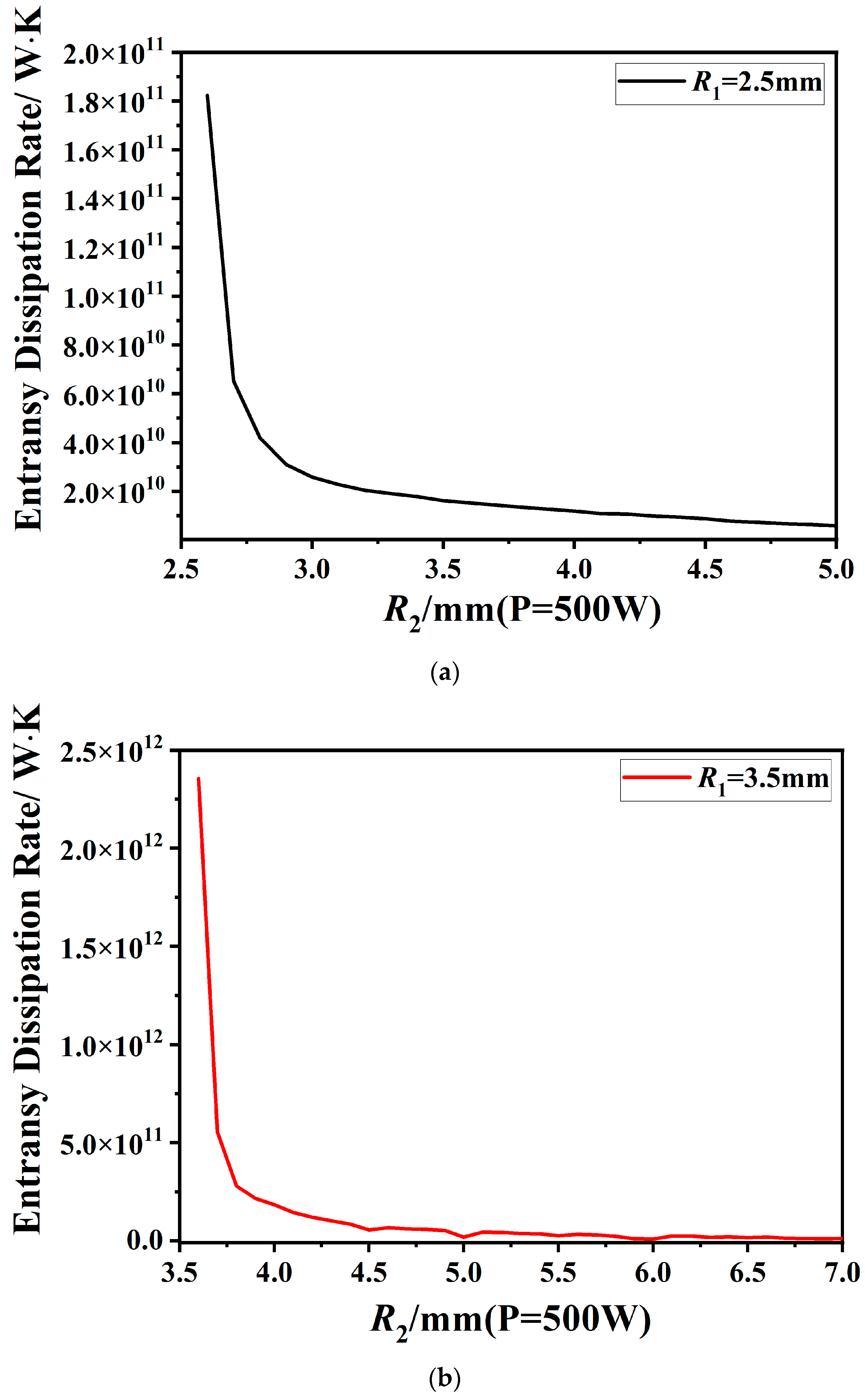
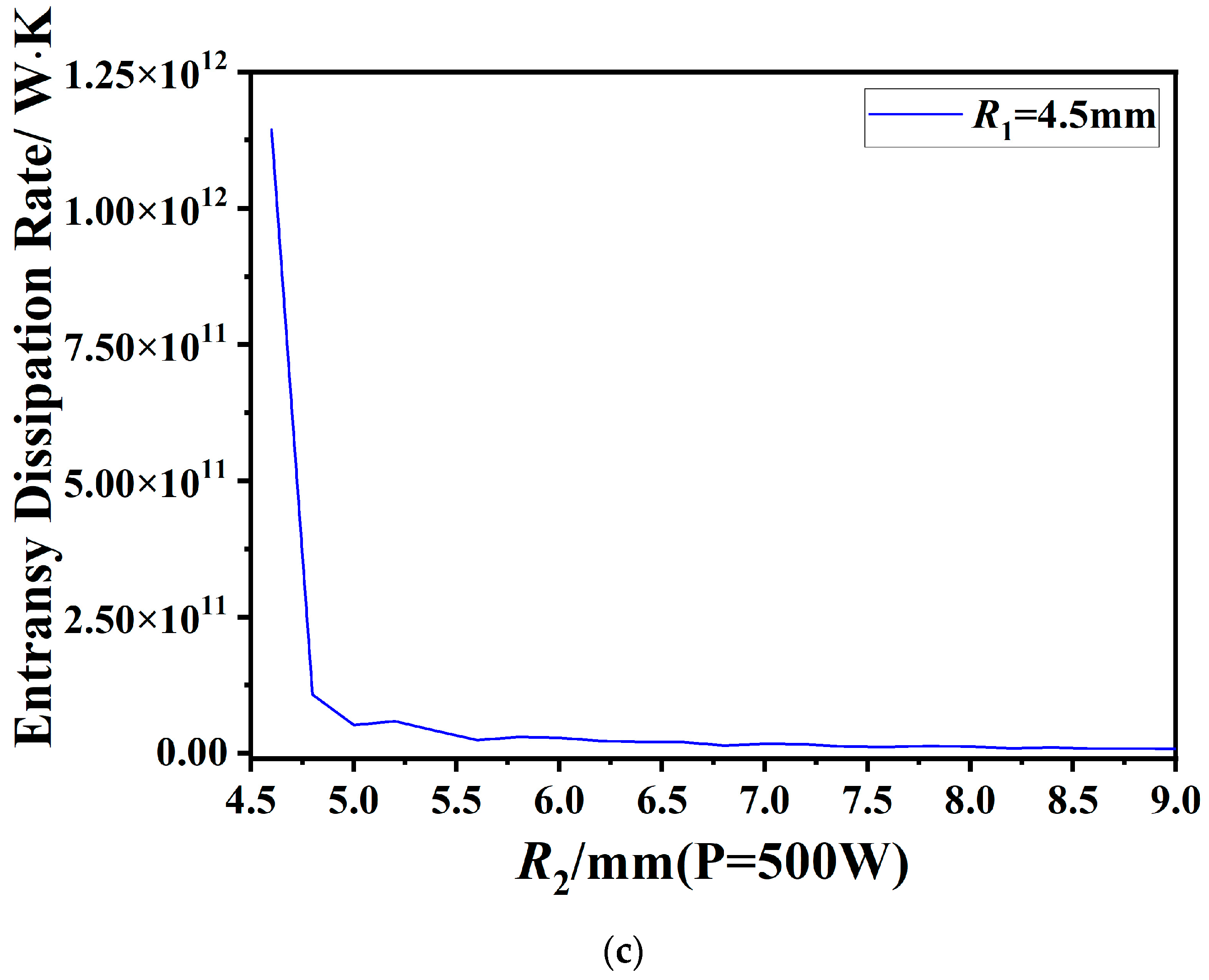
Regarding the radius of the inner ring of the annular laser, we discuss the Variation in the entransy dissipation rate with changes in
R2 when
R1 = 2.5 mm, 3.5 mm, and 4.5 mm under a certain heat input level, as shown in
Figure 4.
As illustrated in
Figure 4a, under the conditions of a power input
q0 of 500 W, a scanning speed
u of 0.005 m/s, and an annular inner radius
R1 of 2.5 mm, it can be observed that the entransy dissipation rate decreases as the hollow ratio decreases. When
R2 is between 2.5 mm and 3 mm, corresponding to the hollow ratio approximately between 0.83 and 1, there is a sharp decline in the entransy dissipation rate. This trend of change also exists in
Figure 4b,c. When
R1 is 3.5 mm, and
R2 is between 3.5 mm and 4 mm, which means the hollow ratio η is between 0.875 and 1, the entransy dissipation rate sharply decreases. When
R1 is 4.5 mm, and
R2 is between 4.5 mm and 5 mm, that is, the hollow ratio η is between 0.9 and 1, there is a marked decline in the entransy dissipation rate. Furthermore, within the range of
R1 values, as
R1 increases, the hollow ratio, which causes a sharp decrease in the entransy dissipation rate, also increases.
The smaller the entransy dissipation rate of the material, the more uniform the temperature gradient field [
24], and the more effective the reduction in the average temperature difference of the material. In the context of surface heating, while ensuring the material reaches its melting point, it is advantageous to minimize the entransy value. When
R1 is 2.5 mm, and the outer radius
R2, with a lower entransy dissipation rate, ranges from 4.5 mm to 5 mm, this corresponds to a hollow ratio η approximately between 0.5 and 0.56. When
R1 is 3.5 mm, and the outer radius
R2, with a lower entransy dissipation rate, ranges from 5.8 mm to 7 mm, the hollow ratio η is roughly between 0.5 and 0.6. When
R1 is equal to 4.5 mm, and the outer radius
R2, with the lowest entransy dissipation rate, ranges from 7.3 mm to 9 mm, the hollow ratio η is between 0.5 and 0.62.
It can be inferred that within the range of R1 values, when the hollow ratio is between 0.5 and 0.56, the entransy dissipation rate is relatively small, which means that laser heating under this parameter can obtain a more uniform temperature gradient field. In addition, when the heat input and hollow ratio are given, the maximum entransy dissipation rate for 3.5 mm is obtained when comparing R1 with 2.5 mm, 3.5 mm, and 4.5 mm.
Given a constant inner annular radius R1, a reduction in the outer annular radius R2, resulting in an increased hollow ratio, leads to a decreased area directly exposed to laser irradiation; consequently, this induces an increase in the average heat flux density, and thus, the temperature gradient field in region A is more uneven, resulting in an increase in the entransy dissipation rate.
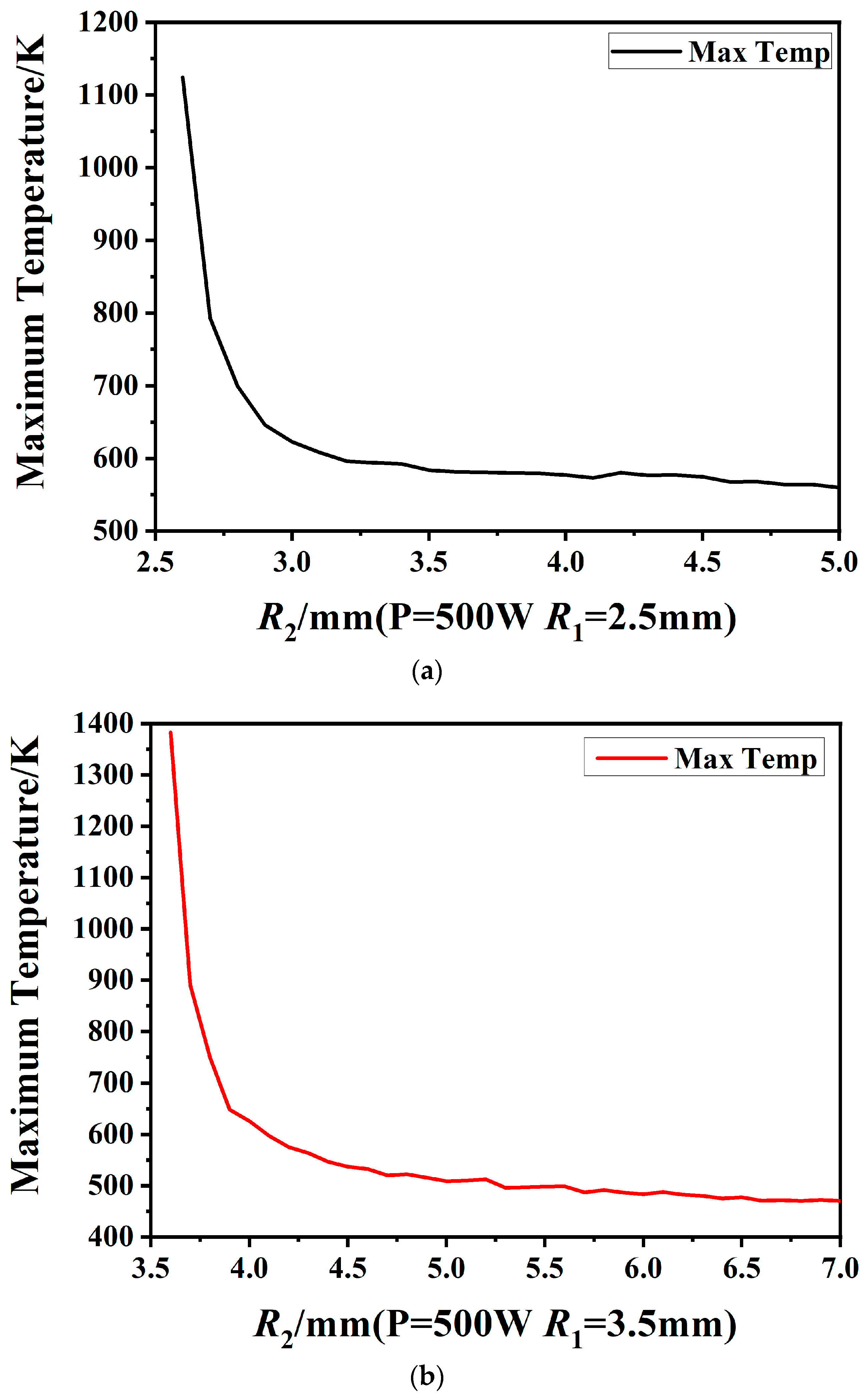
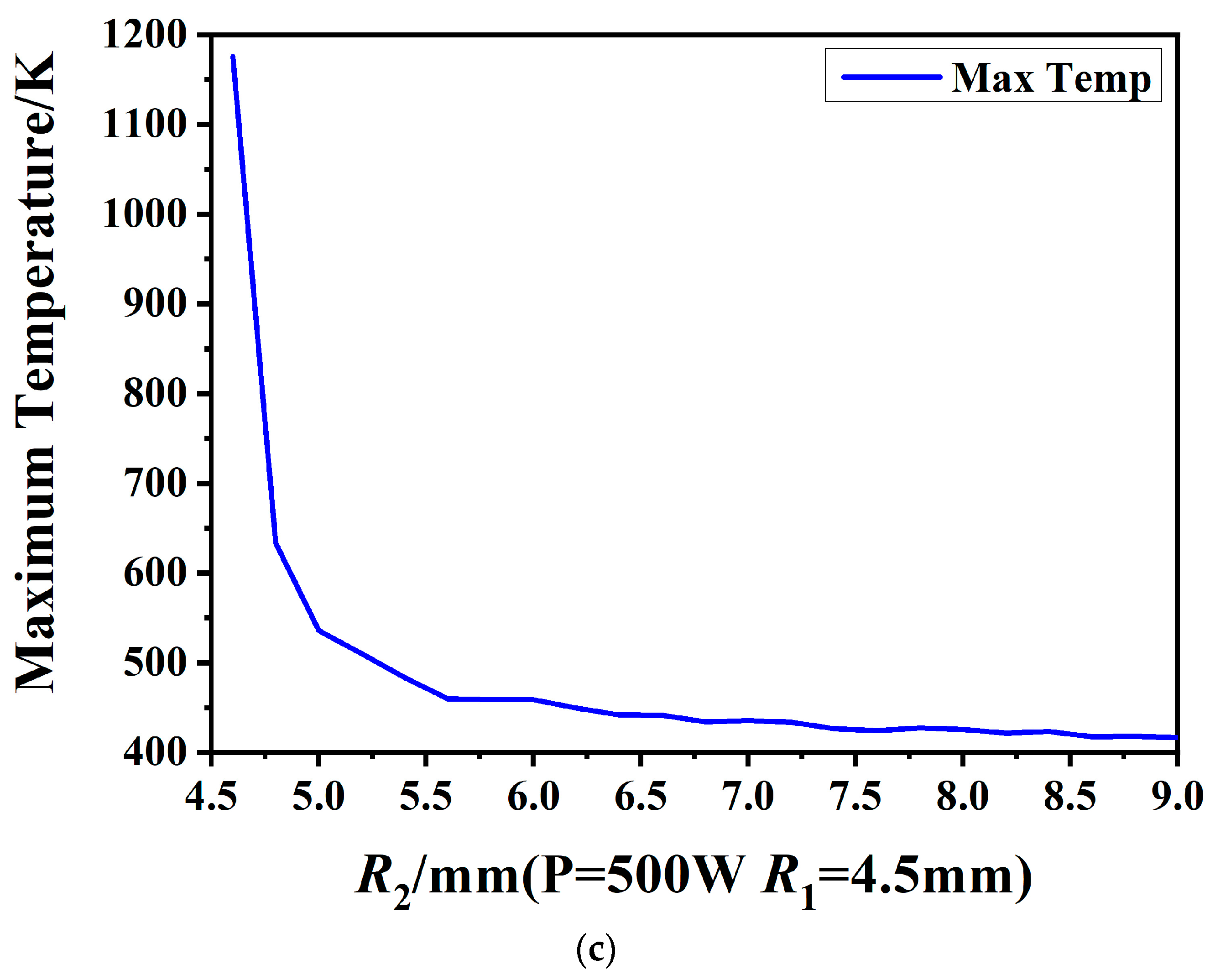
As depicted in
Figure 5a–c, it can be observed that under constant heat input and fixed inner annular radius
R1, the peak temperature within the computational domain decreases with an increase in
R2, which means that the maximum temperature reduces as the hollow ratio diminishes. Furthermore, with constant heat input and a hollow ratio η, for
R1 = 2.5 mm, 3.5 mm, and 4.5 mm, the highest peak temperature is attained at
R1 = 3.5 mm. Among these three annular laser parameters, when
R1 is 3.5 mm, it not only has the highest entransy dissipation rate but also the highest temperature.
Meanwhile, under the condition of ensuring a certain heat input, when R1 = 2.5 mm, the variation curve of its entransy dissipation rate with R2 satisfies the minimum entransy dissipation rate and the minimum maximum temperature within the calculation area.
3.2. The Impact of Outer Radius of Annular Hollow Laser on Entransy Dissipation Rates
Regarding the annular hollow laser’s outer radius
R2, we explored the variations in entransy dissipation rates with the alterations in the inner annular radius
R1 under a scenario where the heat input (
q0/
u) remained constant and the outer annular radius
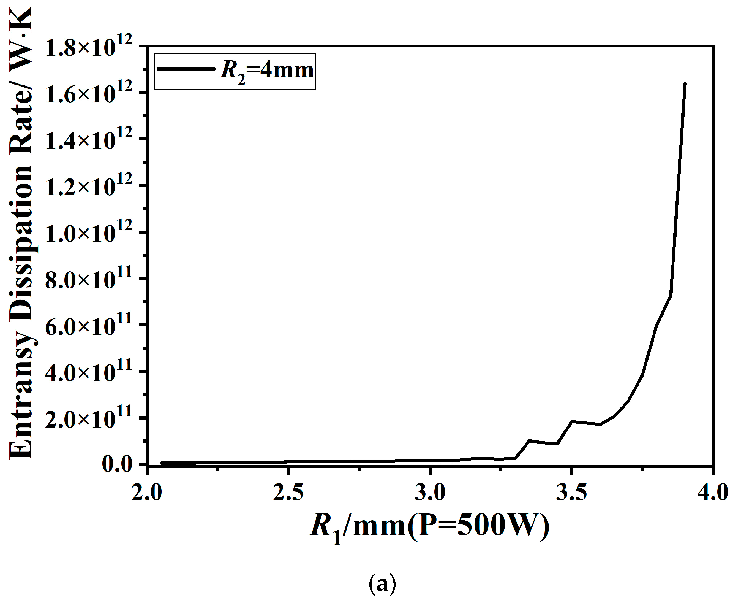
R2 was set at 4 mm, 5 mm, and 6 mm, respectively. The results are depicted in
Figure 6.
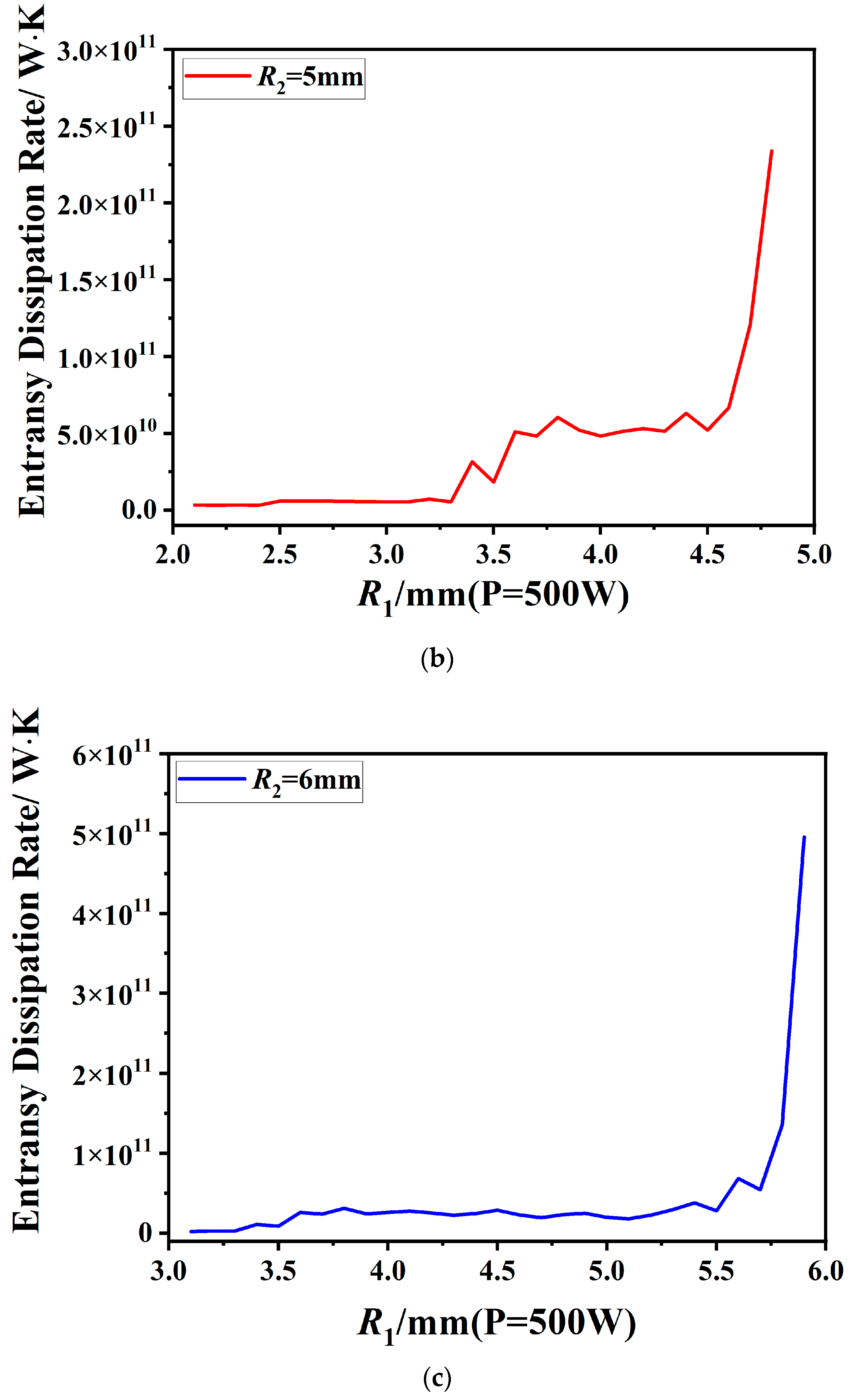
As illustrated in
Figure 6, with constant heat input and a fixed outer annular radius
R2 of the annular heat source, the entransy dissipation rate generally exhibits an upward trend as the inner annular radius
R1 increases.
The calculation area is the inner ring area of the annular laser, and different inner ring radii result in different calculation areas. When the outer radius of the laser is constant, as the inner radius R1 increases, the area directly irradiated by the annular heat source decreases, the average heat flux density increases, and the temperature is higher. Therefore, the temperature gradient field between the laser direct irradiation area and the calculation area A is more uneven, resulting in a higher dissipation rate. R1 directly affects the calculation area, so the entransy dissipation rate varies more dramatically with the radius of the annular laser inner ring.
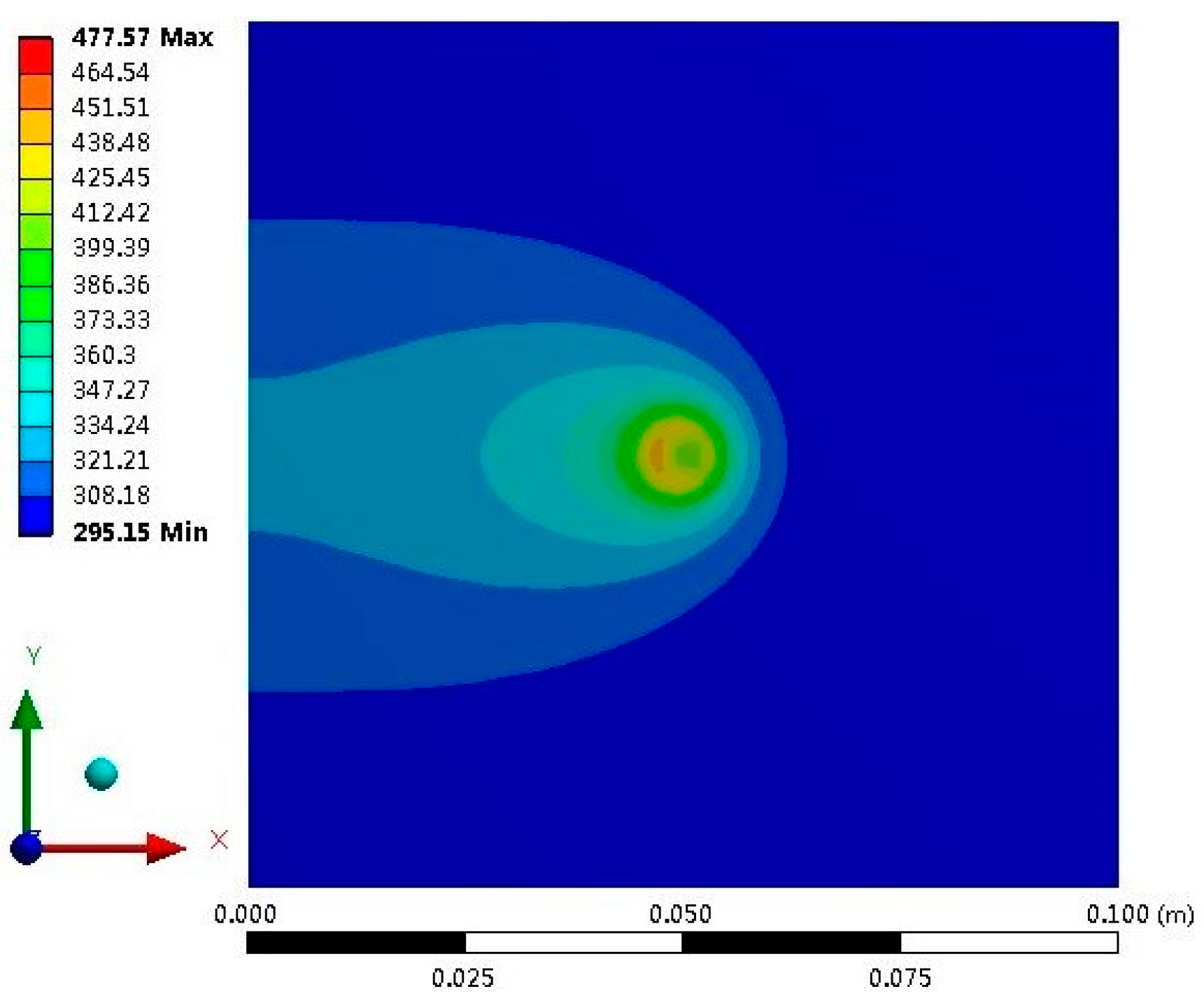
Figure 7 presents the temperature field of the substrate surface under the action of the annular heat source.
It can be observed from
Figure 7 that the highest temperature always occurs in the direct heating zone of the annular laser.
Figure 7 corresponds to the temperature field in
Figure 6b when
R1 is 2.3 mm. It can be seen that the yellow high-temperature zone almost covers the entire circle formed by the outer radius of the annular laser, leaving only a small portion of the green low-temperature zone in the center. It can be seen that the temperature field distribution in the ring and the inner area is relatively uniform, resulting in a lower entransy dissipation rate.
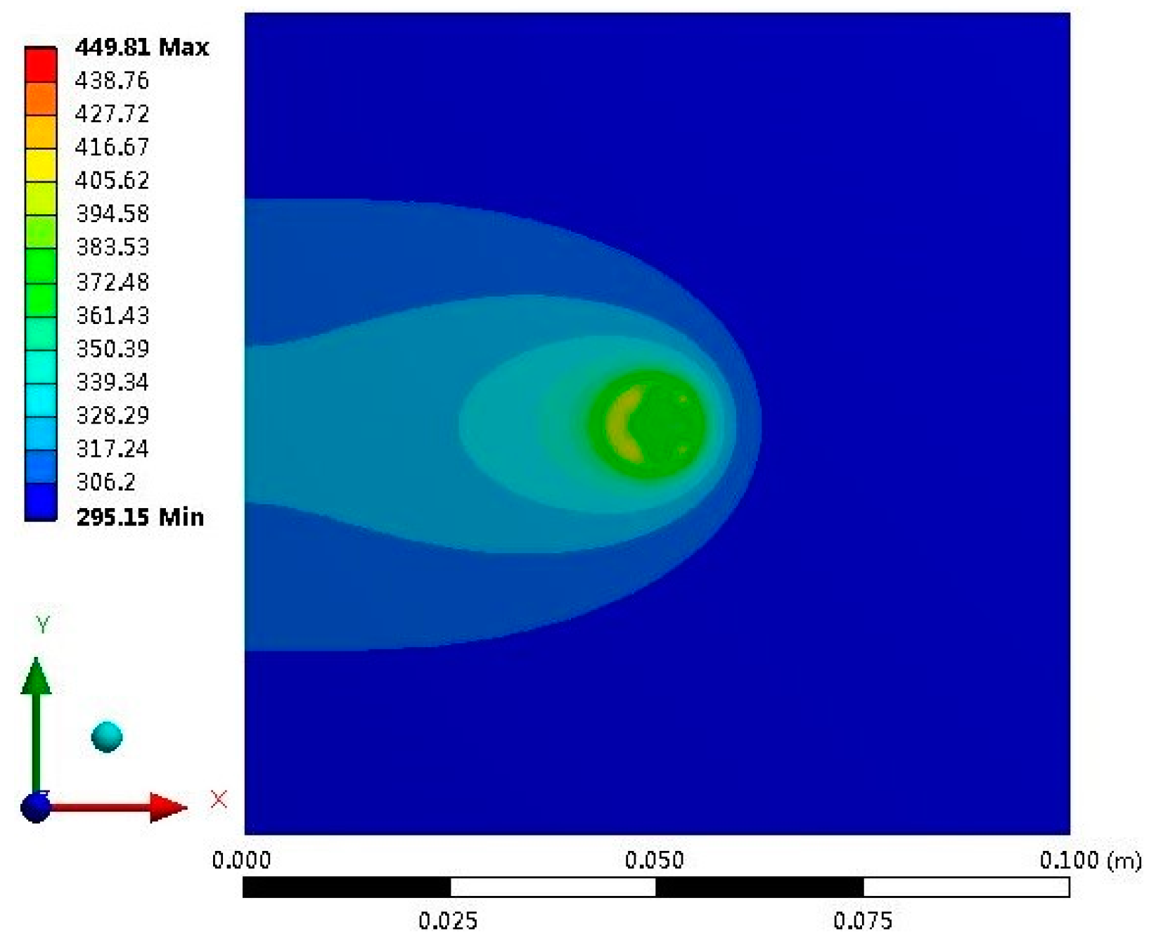
As depicted in
Figure 8, under the specified laser power of
q0 = 500 W, scanning speed of
u = 0.005 m/s, outer annular radius
R2 = 5 mm, and inner annular radius
R1 = 4 mm, the temperature field exhibits a specific distribution pattern. There is no red high-temperature area; instead, it primarily consists of a small yellow temperature zone and a yellow-green temperature zone, with most of the computation area
A presented as a green low-temperature zone. This distribution, compared to
Figure 7 and
Figure 9, indicates that the temperature field in
Figure 7 is slightly more uneven than in
Figure 8, while in
Figure 8, it is relatively more uniform than in
Figure 9. It can be inferred that under these conditions, the entransy dissipation rate is higher than in
Figure 7 but lower than in
Figure 9.
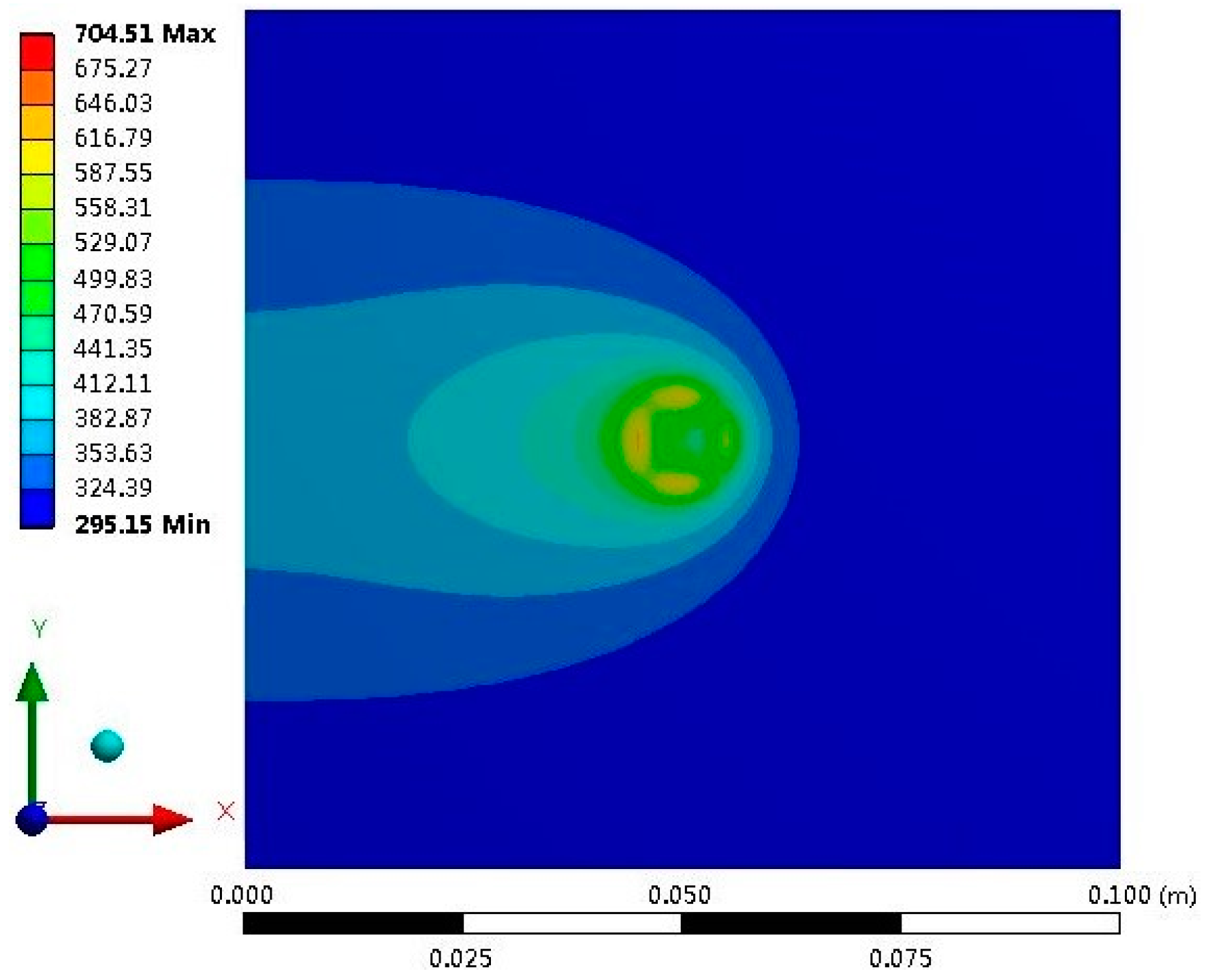
Furthermore, upon adjusting the inner radius to
R1 = 4.8 mm while keeping the other parameters constant, a significant change in the temperature field is observed, as shown in
Figure 9. A small portion of the red high-temperature area and a section of the yellow temperature zone have developed, but the majority of the computation area still remains a green low-temperature zone, with even a blue low-temperature area present. This indicates that under this set of parameters, the temperature field distribution becomes even more uneven, and the entransy dissipation rate significantly increases.
4. Conclusions
From the perspective of heat transfer, with a fixed heat input and the aim of minimizing the dissipation rate, a model was established to select the parameters of an annular laser’s inner and outer radii. The optimal ranges for the inner and outer ring radii, corresponding to the minimization of the material temperature difference, are provided.
The range of hollow ratios that minimize dissipation rates are nearly identical, and within the parameter ranges under consideration, the hollow ratio is between 0.5 and 0.56, the entransy dissipation rate is the smallest, and the temperature field distribution is more uniform. The average heat transfer temperature difference of the parameter combination with the lowest entransy dissipation rate is effectively reduced, and the overall temperature difference is significantly improved. The essence is that the temperature gradient field of the parameter combination with the lowest entransy dissipation rate is more uniform. The minimum of the entransy dissipation rate indicates the minimum loss of heat transfer capacity in the process. This optimized energy utilization not only enhances processing efficiency but also reduces energy consumption, highlighting the energy-saving advantages of the annular laser.
When the heat input and outer annular radius are constant, the entransy dissipation rate increases with an increase in the inner annular radius, implying that the entransy dissipation rate rises with a higher hollow ratio. Conversely, when the heat input and inner radius are constant, the entransy dissipation rate decreases with an increase in the outer radius, indicating that the entransy dissipation rate declines with a lower hollow ratio. Moreover, the radius of the outer radius of the annular laser is constant, and changing the radius of the inner radius has a greater impact on the entransy dissipation rate.
The maximum temperature decreases with a reduction in the hollow ratio. Within the parameters studied, the maximum temperature for the annular laser hollow ratio between 0.5 and 0.56 is relatively small compared with other hollow ratios, aligning with the hollow ratio ranges that minimize the entransy dissipation rate. A higher entransy dissipation rate corresponds to a more uneven distribution of the temperature field.
