1. Introduction
With the development of renewable energy sources such as wind and solar power, the stability of the power grid faces increasing challenges. Flywheel energy storage, characterized by a rapid charge and discharge response, high frequency, and long lifespan, can not only meet the energy storage requirements for voltage support and frequency stability in high-proportion renewable energy grids [
1,
2,
3,
4] but can also be applied to short-term high-frequency peak shaving in independent energy systems [
5]. Flywheel energy storage has garnered widespread attention and application worldwide.
During the entire service life, the flywheel energy storage system frequently charges and discharges, resulting in frequent fluctuations in the stress state of the rotor core, which poses a significant challenge to the fatigue life of the rotor. When it operates across a significant speed range from 0 to 100% depth of discharge (DoD), the flywheel’s rotational speed will decrease from the maximum operating speed
n1 to the minimum operating speed
n2. In most cases,
n2 ≤ 0.5
n1; of course, the process could also be the reverse. Therefore, the stress range experienced by the material will be substantial. In this paper,
R represents the ratio of the maximum stress at the lowest rotational speed to the maximum stress at the highest rotational speed. Fatigue life prediction quantifies the effective working time before failure occurs in mechanical structures, while fatigue accumulation damage reflects their failure criteria, based on extensive data from tests, maintenance, and diagnostics. From components to entire mechanical systems, scholars worldwide have conducted in-depth research on fatigue issues involving different structures and materials, proposing relevant fatigue analysis methods and theories ranging from theoretical analysis and experimental validation to engineering applications [
6,
7,
8,
9,
10].
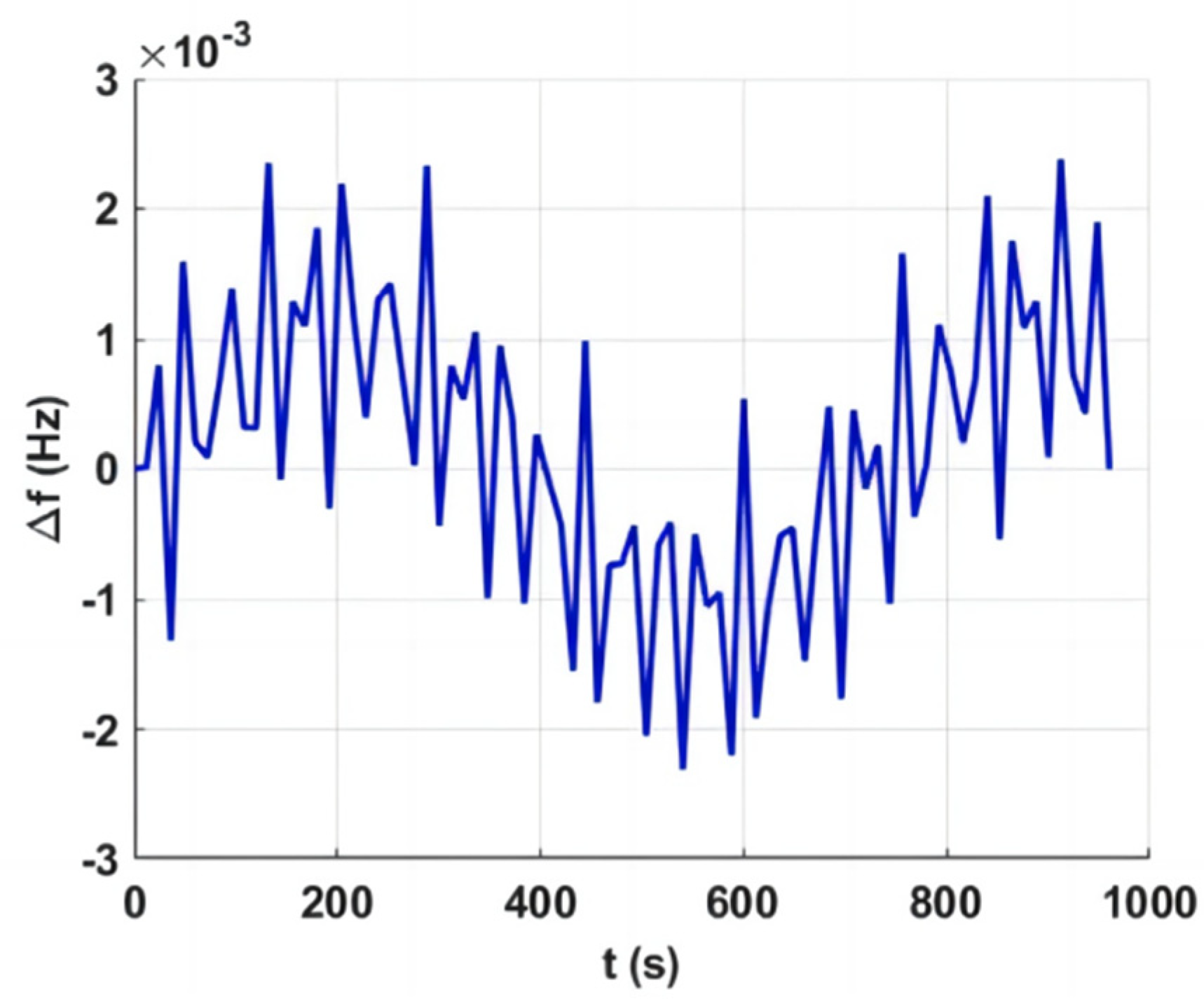
Figure 1 illustrates the fluctuation frequencies of the power grid [
6], where Δ
f represents a deviation from the nominal frequency of 50 Hz. These frequency fluctuations indicate the necessity for flywheel energy storage systems to efficiently charge and discharge at high frequencies corresponding to these variations. Some scholars have conducted in-depth research on fatigue life prediction models and have achieved decent results [
11,
12,
13]. However, due to the inherent variability of fatigue life, the accurate prediction of these models remains challenging. Philippa Moore et al. compare the application of the crack mouth displacement (CMOD) and load line displacement (LLD) methods in the determination of the critical J integral in SENB specimens [
14].
Understanding the prediction model of flywheel rotor fatigue life and determining a reasonable stress level in the core deserve further investigation. 30Cr2Ni4MoV, a high-strength alloy steel, is a commonly used material for flywheel rotors. This article will delve into the fatigue life of the material itself. The characteristics and influencing factors of crack propagation and the fatigue properties of the material were studied. The impact of internal defects and operating conditions within the rotor on the fatigue life of the flywheel rotor were also studied.
2. Basic Mechanical Properties
The material selection for flywheel energy storage rotors falls into two categories: composite materials and high-strength alloy steel. A decade ago, it was widely believed that composite materials, with their superior circumferential strength, were more suitable for large energy storage flywheels. However, a series of safety incidents involving high-speed composite flywheels, along with their higher cost, have reignited interest in high-strength alloy steel flywheels. 30Cr2Ni4MoV steel, with its excellent hardening ability, welding performance, fracture toughness, and stress resistance, has traditionally been utilized in the fabrication of large steam turbine rotor components such as forged low-pressure rotors, welded low-pressure rotor shafts, disks, and intermediate shafts, which require high strength and toughness. As such, 30Cr2Ni4MoV steel has also emerged as an ideal material choice for large energy storage flywheel rotors. It should be noted that, in addition to the 30Cr2Ni4MoV studied in this paper, other high-strength alloy steels such as 35CrMoA, 42CrMoA, and 30CrMnSiNi2A are also commonly used materials for flywheel energy storage rotors.
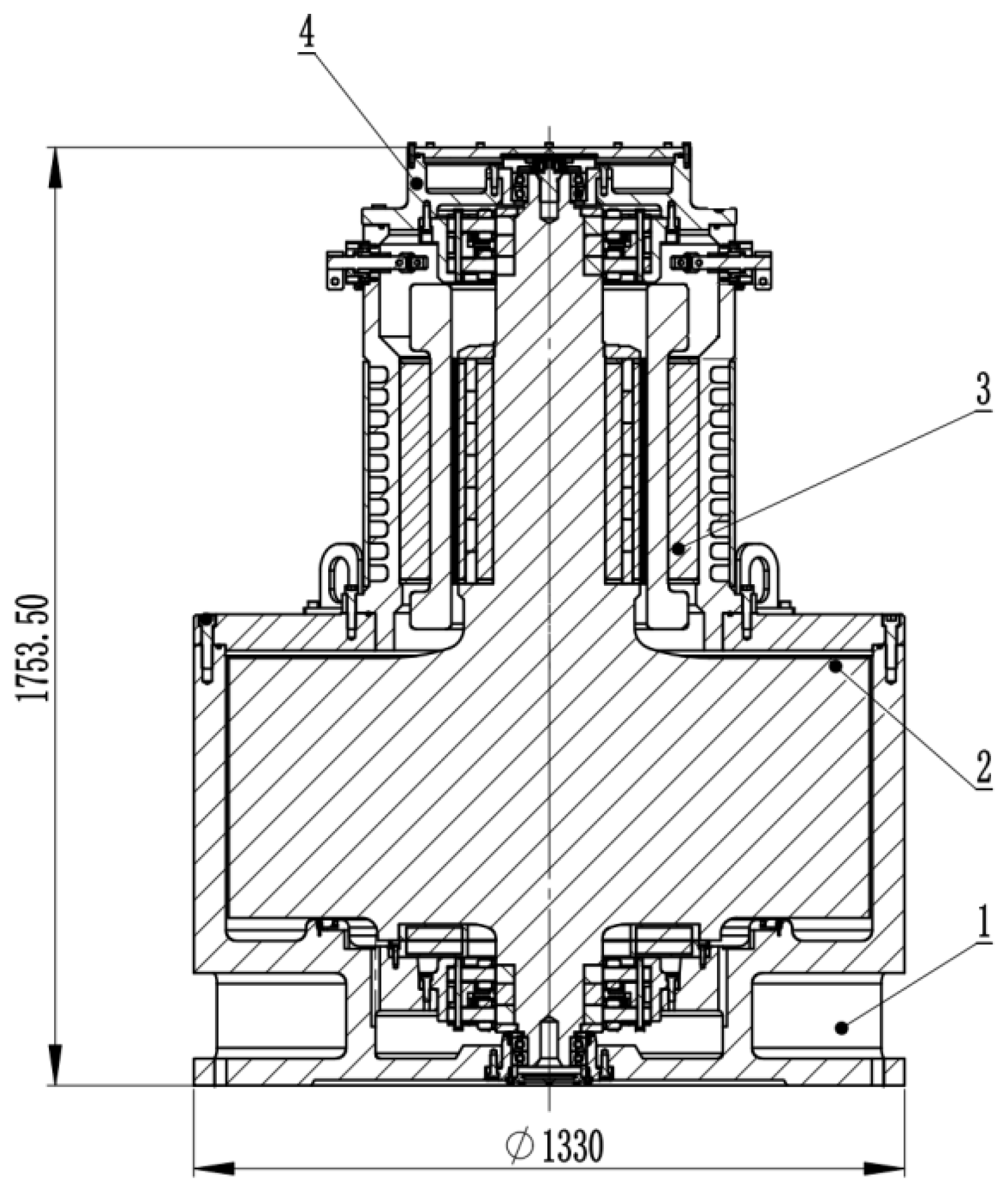
Figure 2 presents the schematic diagram of the flywheel energy storage prototype designed and developed by our team, which is primarily composed of the flywheel rotor system, high-speed motor, and magnetic bearings. The maximum energy storage capacity of the flywheel energy storage unit is 50 kWh, with the rotor material being 30Cr2Ni4MoV steel. The research in this paper is primarily based on the rotor material and rotor structure of this prototype.
2.1. Mechanical Strength
The mass fractions of trace elements in the material’s chemical composition are presented in
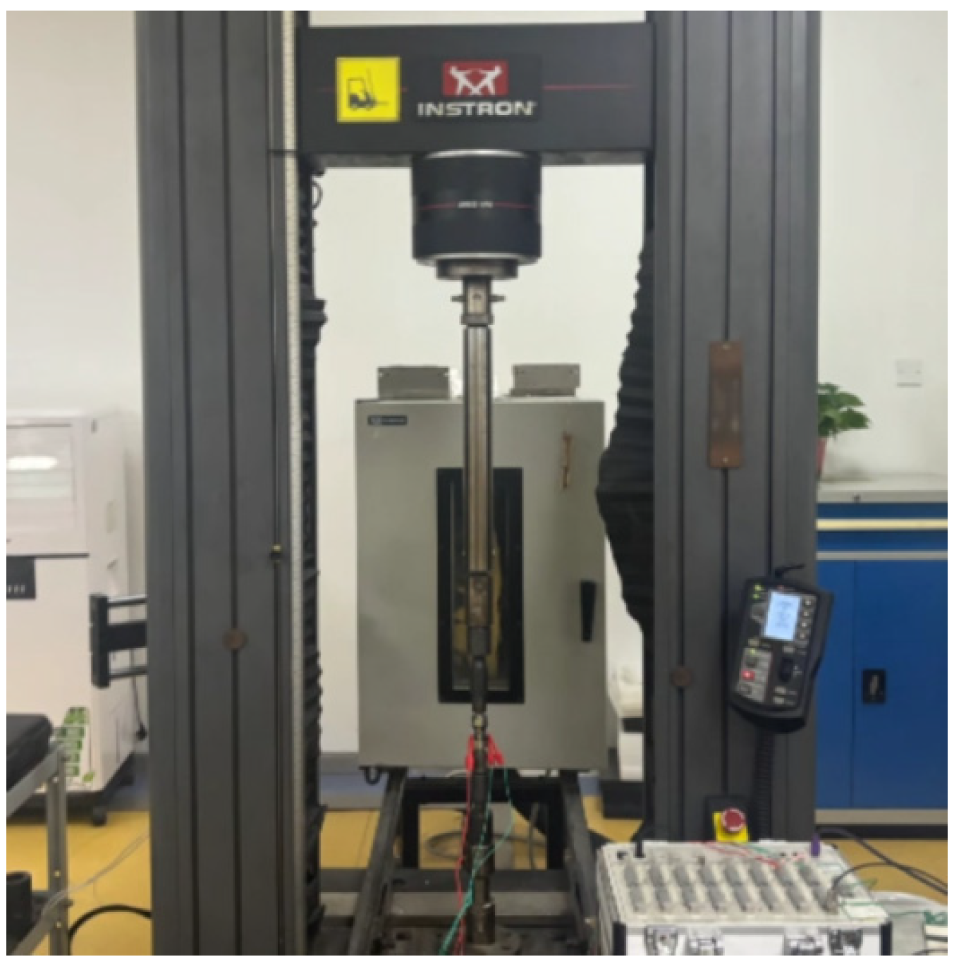
Table 1, while the equipment setup for the tensile test is illustrated in
Figure 3. The mechanical properties of 30Cr2Ni4MoV alloy steel are shown in
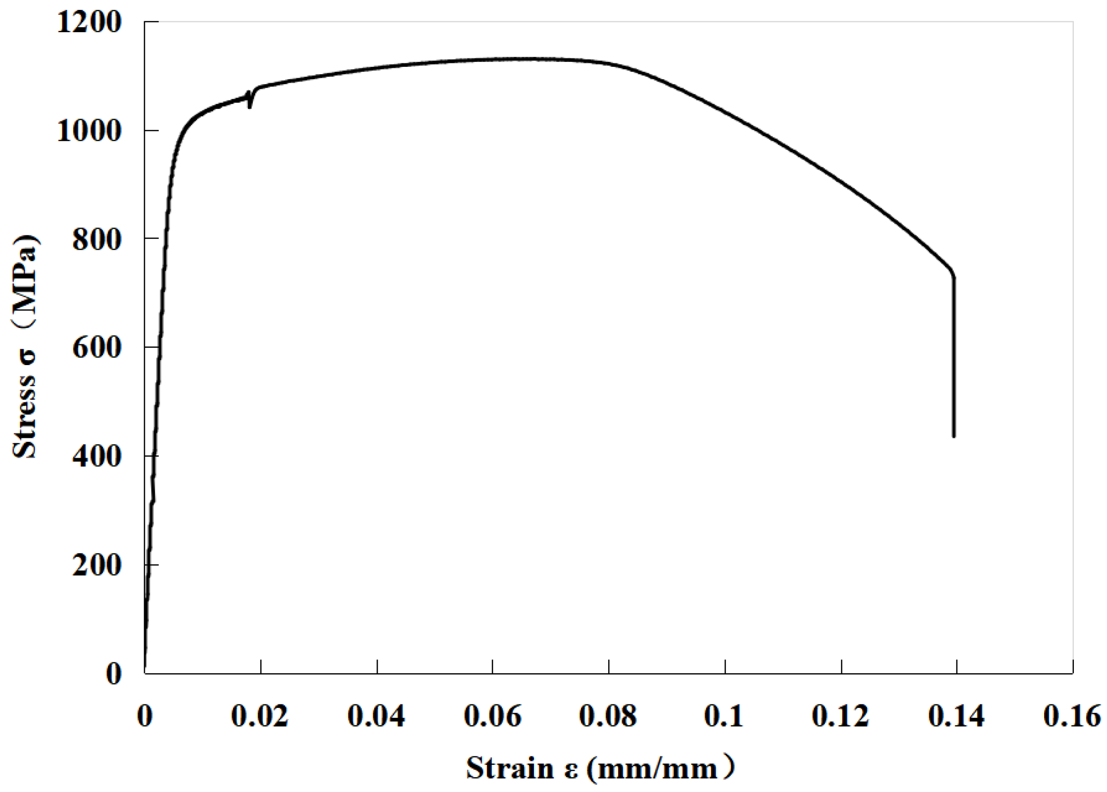
Table 2. The stress–strain curve is shown in
Figure 4. The test results indicate that the yield strength of the material is 992 MPa, and its tensile strength is 1130 MPa. Typically, the yield strength of this material ranges around 760 MPa, with a higher-grade variant approximately ranging around 830 MPa [
15]. Therefore, the results demonstrate that the tested material sample possesses excellent yield strength and tensile strength.
2.2. Crack Propagation Properties
The actual lifespan of a mechanical component consists of both the crack initiation lifespan and the crack propagation lifespan. For large cross-section components with inherent defects, their crack initiation lifespan is virtually zero. Therefore, the service lifespan of the component is determined by its crack propagation lifespan. Under fatigue loading, as defects in the component gradually expand from the initial crack size to the critical crack size, the component experiences unstable fracture. Consequently, the crack propagation lifespan of the component relies on the crack propagation rate, denoted as da/dN, which is an indispensable material property for lifespan estimation and “damage tolerance” design.
Based on the literature [
16,
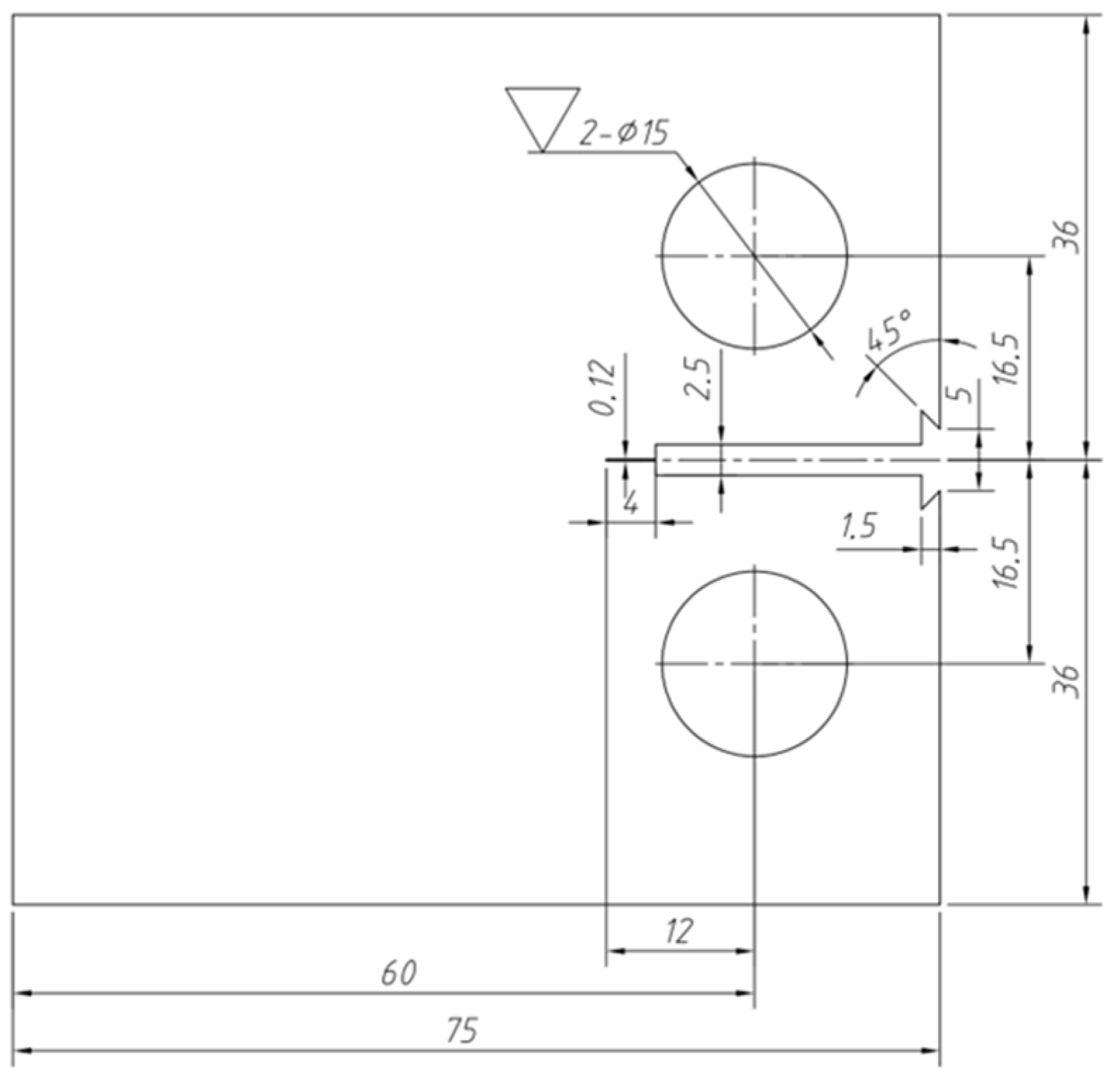
17], crack propagation tensile specimens of rotor materials were designed and prepared. The configuration and dimensions of the specimens are as shown in
Figure 5, with a width of 72 mm and thickness of 15 mm. The initial crack length is 4 mm.
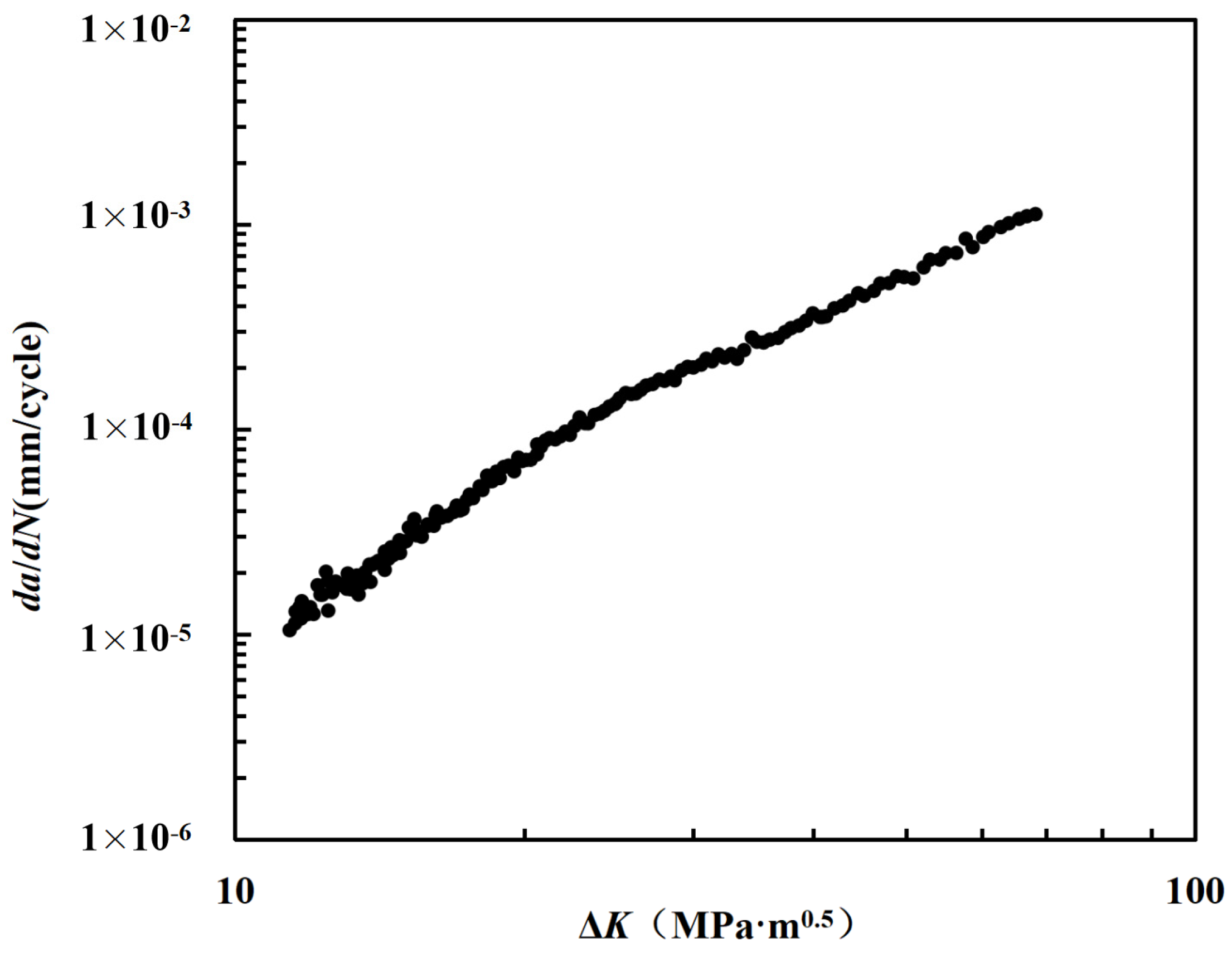
Figure 6 shows the relationship curve between the crack growth rate
da/
dN and the stress intensity factor range Δ
K. Using the Paris formula,
a is the crack length,
N is the number of cycles, and
C and
m are undetermined constants. The experimental data were processed to obtain the fitting curve between the steel crack growth rate
da/
dN and the stress intensity factor range Δ
K.
Figure 7 shows a comparison between the calculated values of the fitting formula and the experimental results and other literature results. The results show that the calculated values of the fitting formula are in good agreement with the experimental values, indicating that the fitting results have good accuracy and can be used to calculate the crack propagation rate of the material under different stress intensity factor ranges Δ
K. The results are also similar to those of other studies in the literature, but when Δ
K < 35 MPa∙m
0.5 and Δ
K is the same, the crack propagation rate of the test piece in this paper is higher than the literature value. After Δ
K > 35 MPa∙m
0.5, the results are opposite. This is an interesting phenomenon, and this article suggests that it may be due to differences in loading methods between the two.
The research results indicate that the yield strength of 30Cr2Ni4MoV steel quenched at 840 °C and tempered at 600–605 °C can reach 760–900 MPa. The strength of ultra-pure 30Cr2Ni4MoV steel screen clothing quenched at 840 °C and tempered at 560–575 °C can reach 965–1035 MPa [
18]. Different heat treatment processes can give 30Cr2Ni4MoV different yield and tensile strengths while also affecting the fracture toughness of the material. The increase in yield strength helps to improve the strength safety factor of materials during use. However, on the other hand, pursuing too high of a yield strength can lead to a decrease in the fracture toughness of materials, which is also detrimental to the safe operation of equipment. It is necessary to seek a balance between the two results. Therefore, it is necessary to explore the relationship between material fracture toughness and yield strength.
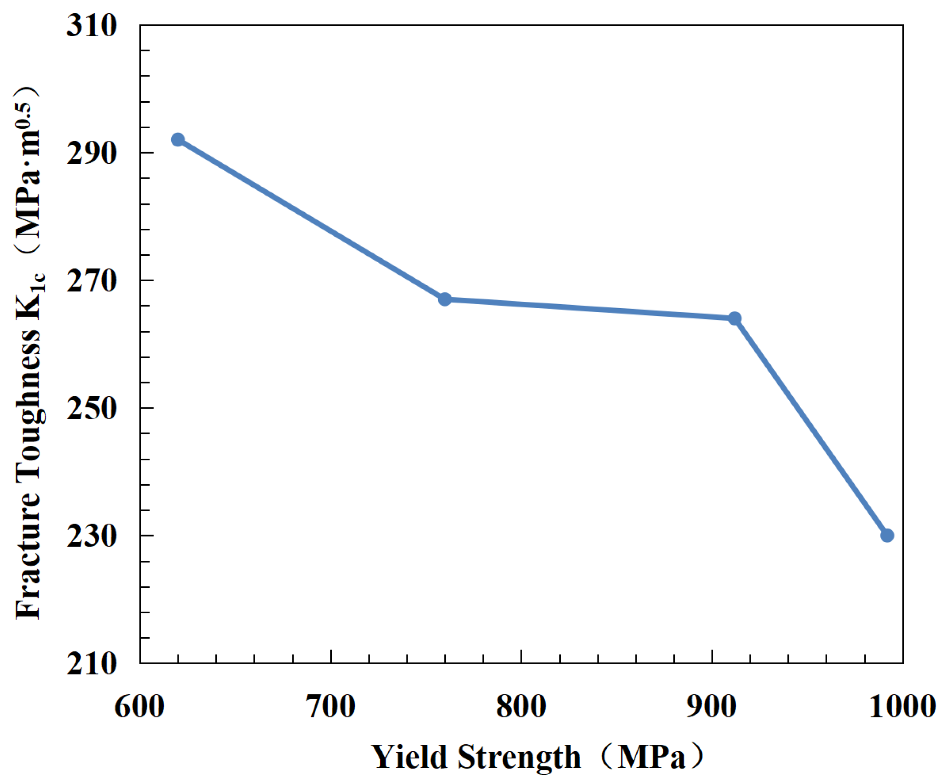
Figure 8 shows the relationship between the material fracture toughness K1C and material yield strength. The results show that as the yield strength increases, the fracture toughness of the material decreases significantly. When the yield strength of the material is increased from 630 MPa to 990 MPa, the fracture toughness of the material decreases from 292 MPa∙m
0.5 to 230, a decrease of 21%. This result indicates that in practical applications, one cannot blindly pursue the improvement of material yield strength.
3. Fatigue Life
3.1. SN Fatigue Life Curve
This section explores the fatigue life characteristics of 30Cr2Ni4MoV steel and conducts fatigue life tests, considering factors such as maximum stress, average stress, and the stress ratio to explore their impact on fatigue life.
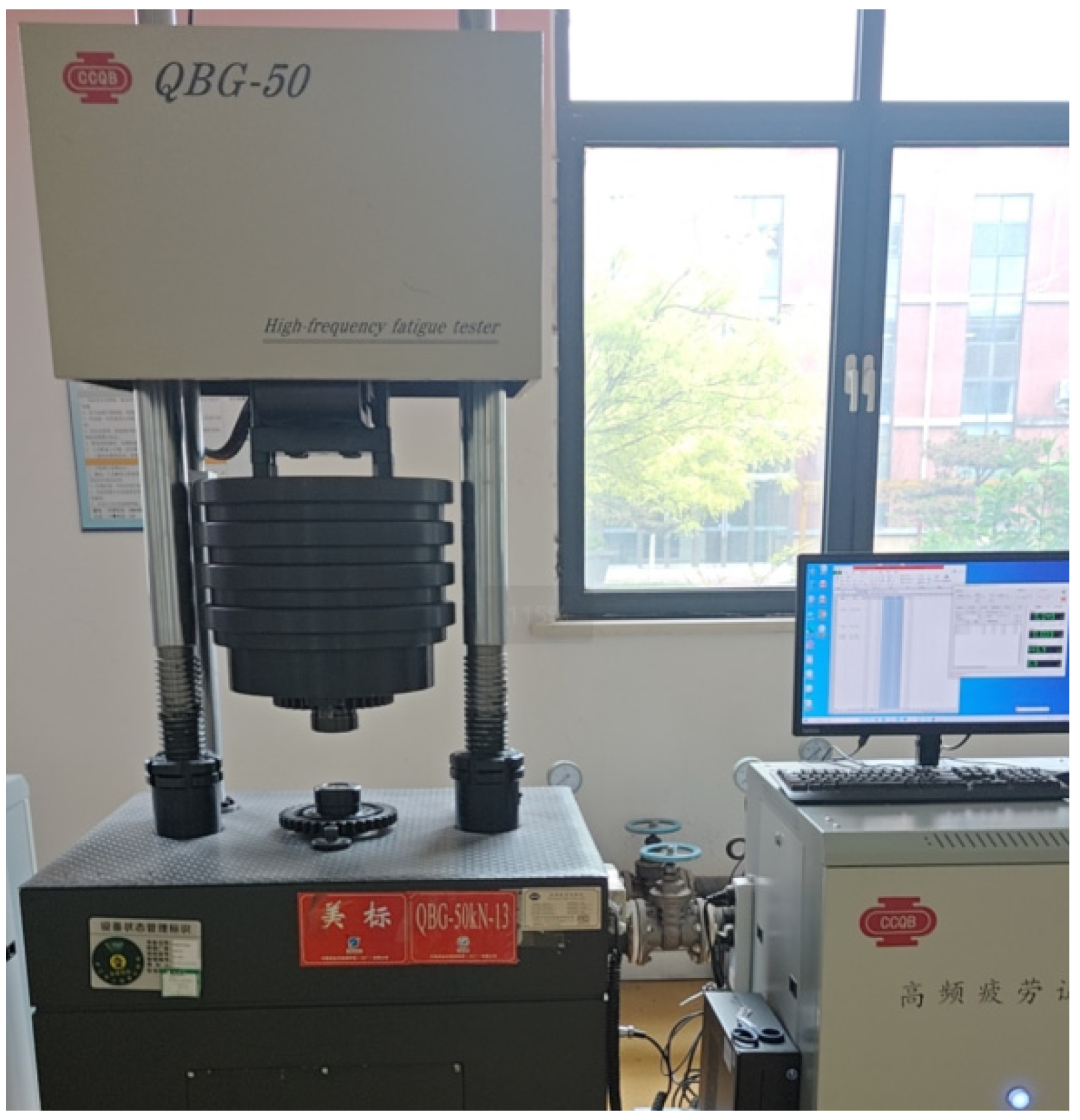
Figure 9 shows the fatigue testing equipment, a QBG-50 model, with a test frequency of 110 Hz. The equipment has a maximum tensile force of 250 kN and a maximum power of 3.5 kW.
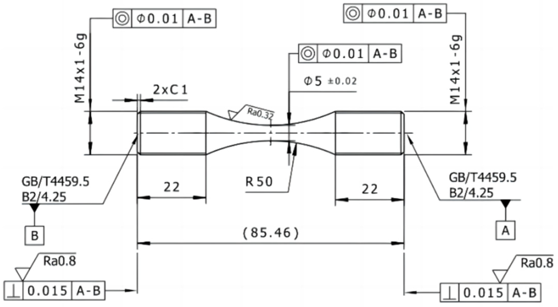
Figure 10 displays the dimensional specifications of the test specimen.
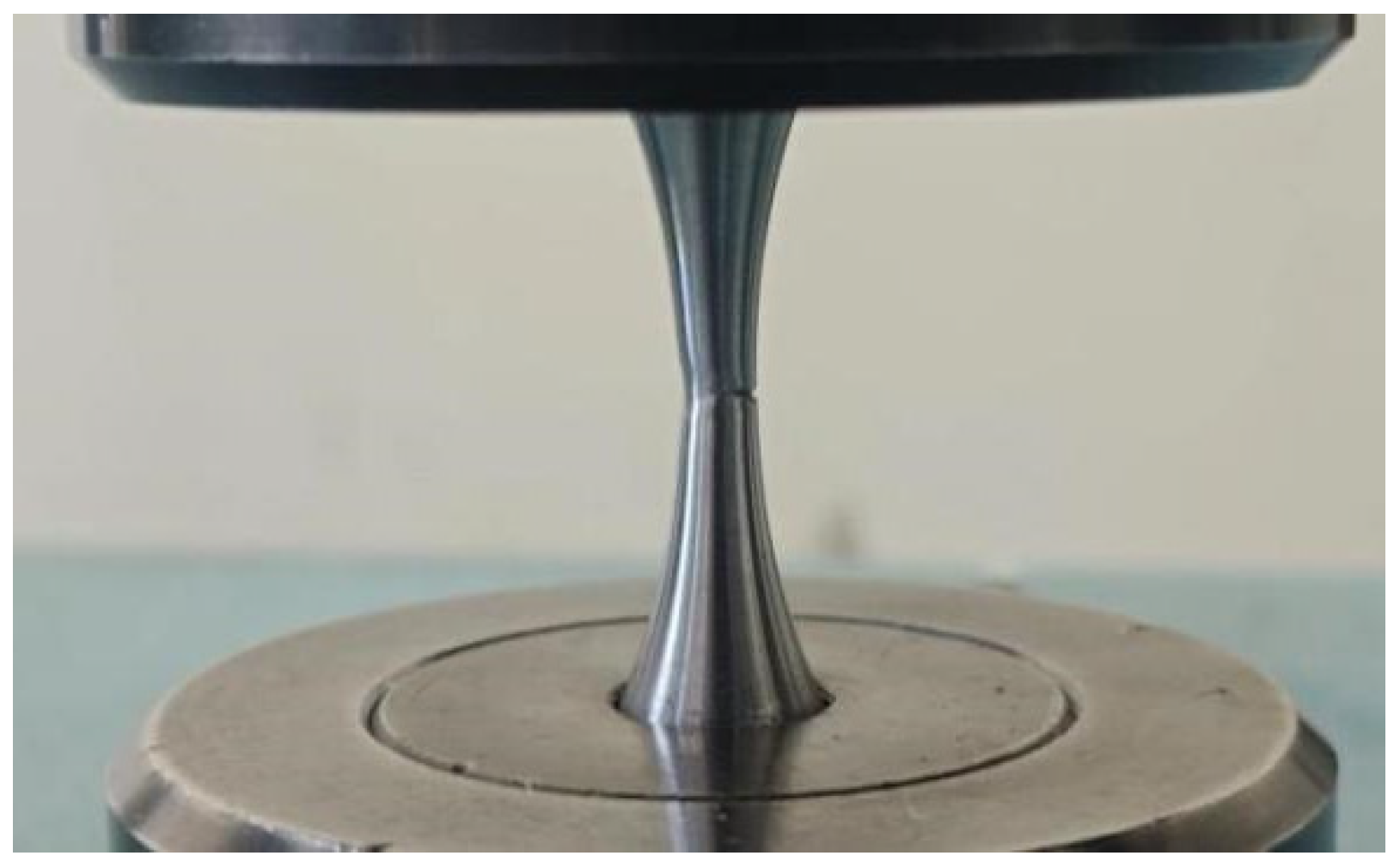
Figure 11 shows the state of the test piece in the final stage of fatigue testing, where the test piece is in a state that is about to break but is not yet broken. From the graph, it can be analyzed that during fatigue fracture of the test piece, a crack forms from one side and gradually expands, eventually forming a crack opening until the final fracture. This process indicates that cracks are formed from the surface rather than inside the test piece.
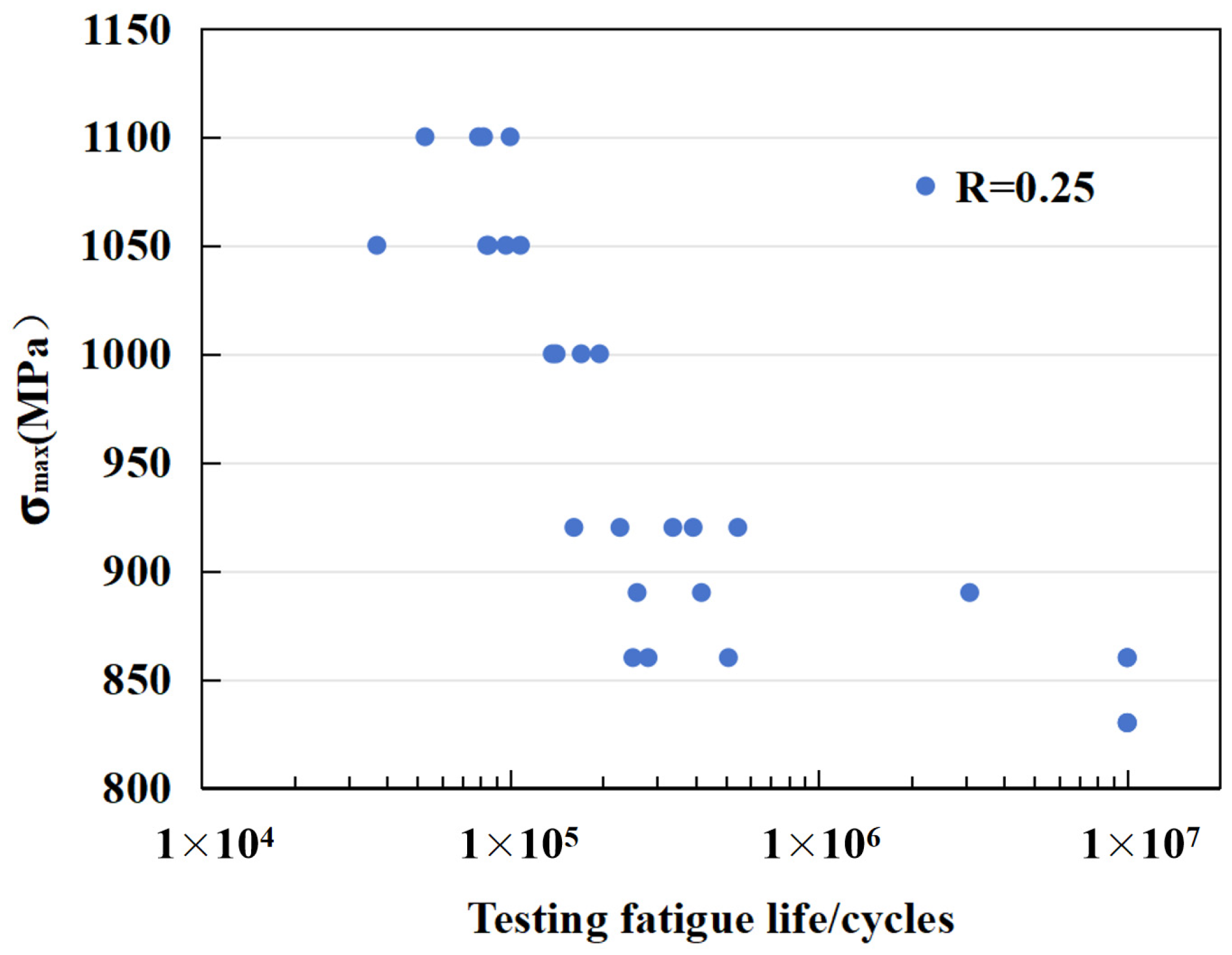
Figure 12 illustrates the relationship between fatigue life and maximum stress. To closely simulate the real operational conditions of flywheels, a stress ratio of 0.25 was employed. It can be observed from the figure that when the maximum stress decreases to 830 MPa, the material exhibits a fatigue life exceeding 10
7 cycles. The figure also demonstrates significant variability in fatigue life, which contributes to the challenges in achieving ideal predictions using current fatigue life models. Therefore, this paper suggests adopting a conservative design approach in fatigue life design.
3.2. Factors Influencing Analysis
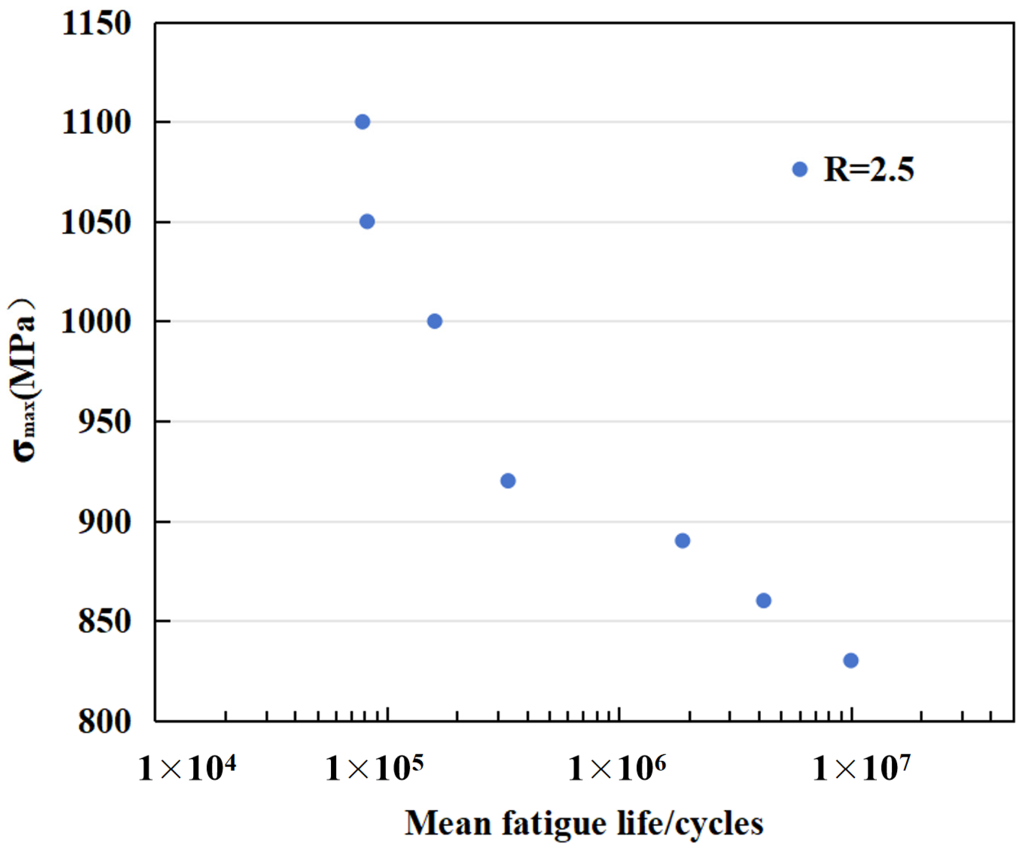
To clearly demonstrate the relationship between fatigue life and stress,
Figure 13 illustrates the correlation between fatigue life and mean stress. From the graph, it is evident that on a logarithmic scale, fatigue life increases approximately linearly with decreasing maximum stress. This observation aligns well with the predictions of the Wöhler model. The stress–life prediction method is the most widely used and earliest proposed engineering approach, based on the S–N curve theory. The early renowned Wöhler curve equation (S–N curve equation) selects stress amplitude as the fatigue damage control parameter, neglecting the influence of plastic stress and hence being suitable for predicting medium-to-high cycle fatigue life. The Wöhler equation appears as a straight line on a log–log plot, and this logarithmic linear form has been extensively adopted by subsequent fatigue models. The equation is formulated as:
where
represents stress amplitude,
denotes the fatigue strength coefficient, and
b signifies the fatigue strength exponent.
The fitting of experimental results to the fatigue strength coefficient and fatigue strength exponent yields the following regression results:
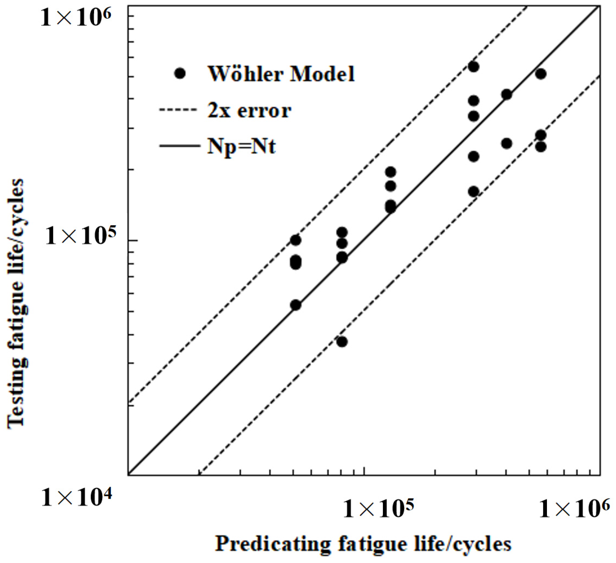
Figure 14 presents a comparison between the model calculation results and experimental test results. As shown in the figure, the majority of the model’s predicted results and the experimental measurements have errors within a factor of two, confirming that the model predictions possess a certain level of accuracy. Of course, this criterion is relatively lenient considering the variability of fatigue life.
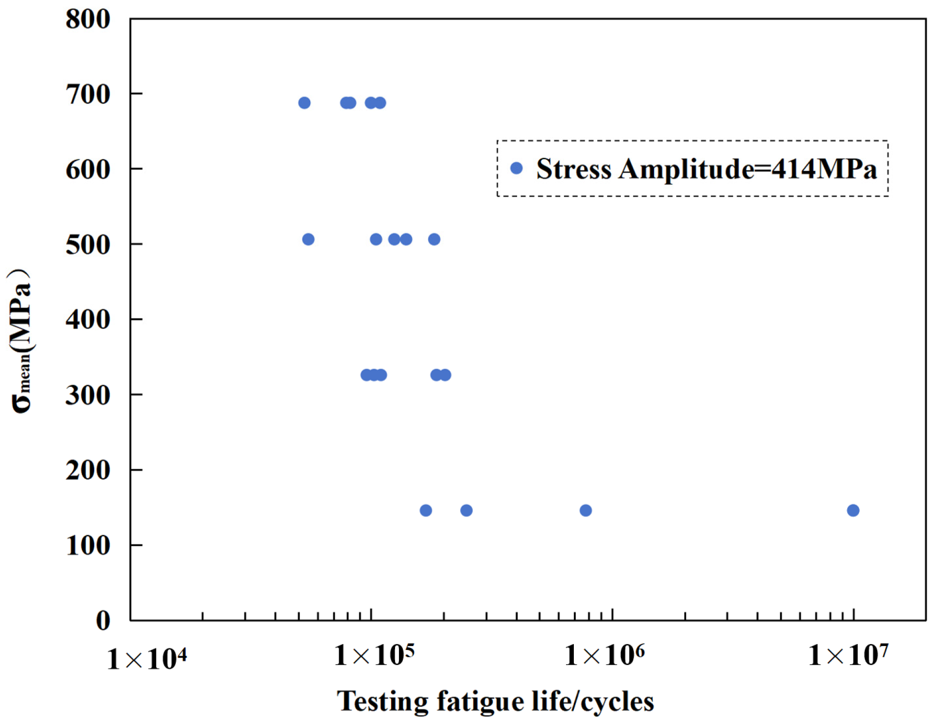
Figure 15 illustrates the distribution of maximum mean stress of a material under various fatigue life testing cycles. The horizontal axis represents the number of fatigue life cycles (logarithmic scale), and the vertical axis displays the stress amplitude in MPa. The graph shows that as the fatigue life increases, the maximum mean stress that the material can withstand gradually decreases. Specifically, as the testing life increases from 10
4 cycles to 10
7 cycles, the maximum mean stress drops from around 600 MPa to about 300 MPa.
The results indicate that, even when the stress amplitude remains the same, different mean stresses can lead to significantly different fatigue life outcomes. It is thus evident that it is essential to correct the stress amplitude, as failure to correct it would result in a fatigue life prediction that differs significantly from the actual results. Of course, the same outcome would be observed when the mean stress is constant but the stress amplitude varies. Therefore, both stress amplitude and mean stress must be taken into account during fatigue life prediction. In the model fitting of this paper, although no correction was performed on the stress amplitude, a relatively satisfactory prediction result was still achieved. This is because the stress ratio used in this part of the test results was consistent; in other words, the variation in stress amplitude was aligned with the variation in mean stress. Therefore, to develop a fatigue life prediction model with good predictive performance, it is imperative to consider the impact of both stress amplitude and mean stress.
The influence of the stress ratio
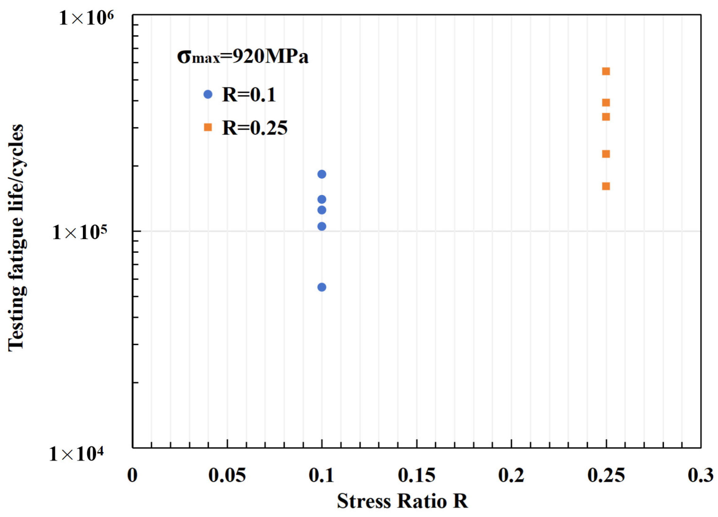
R on fatigue life is depicted in
Figure 16. To minimize extraneous factors, the maximum stress is consistently maintained at 920 MPa. As the stress ratio increases from 0.1 to 0.25, the mean fatigue life extends from 121,600 to 332,800 cycles, a 2.7-fold increase. This indicates that, similar to lithium-ion batteries, flywheel energy storage rotors exhibit analogous lifetime characteristics, where shallow cycling promotes longevity. Despite their fundamentally distinct underlying principles, their external behaviors manifest similarities.
4. The Impact of Internal Defects on Fatigue Life
4.1. Theoretical Foundation
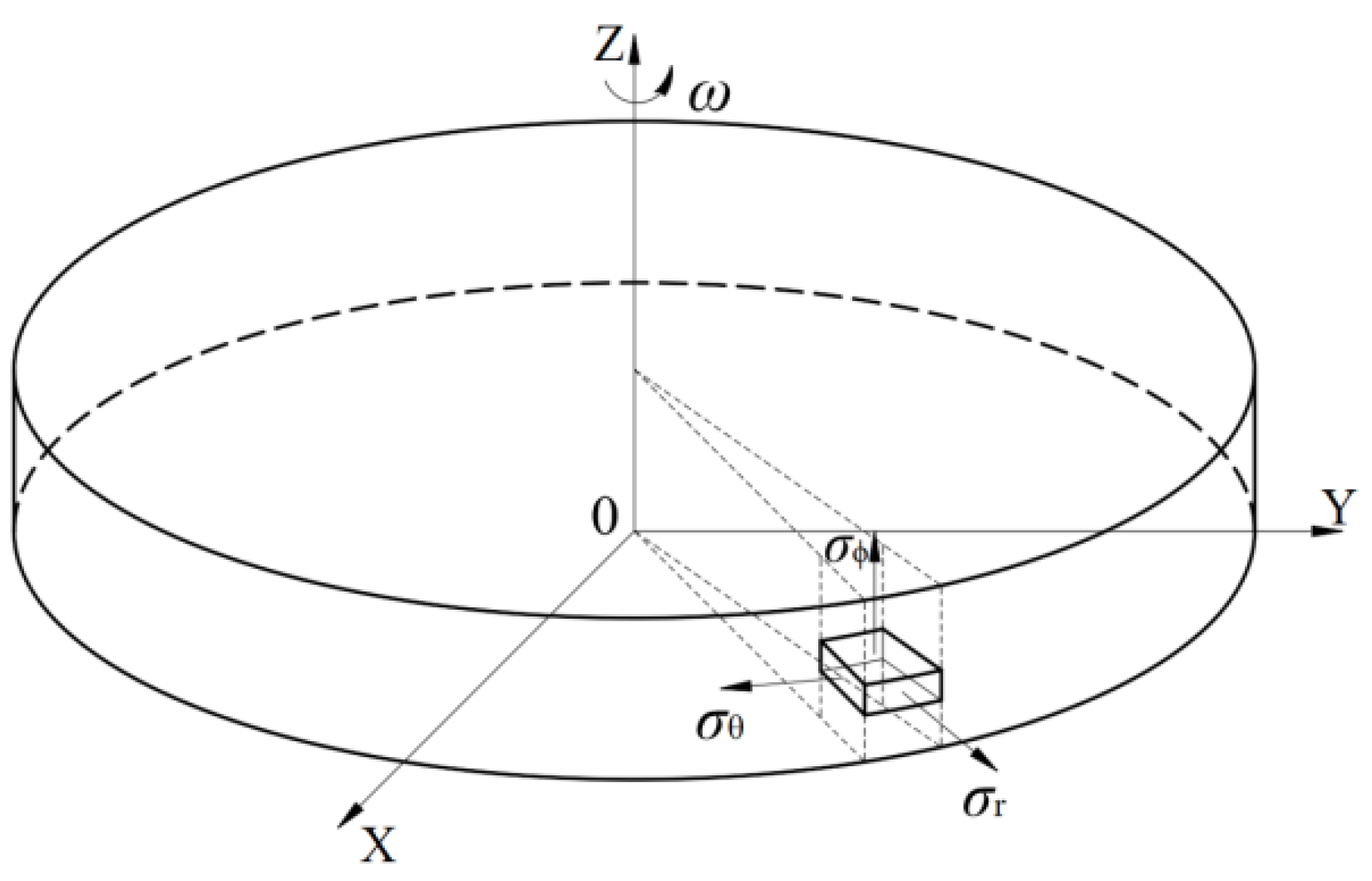
Metallic flywheels are typically designed as either thick-walled annular rings or solid disks, with the latter being a special case of the annular ring configuration. During rotation, the flywheel experiences three primary stress directions: radial stress σ
r, tangential stress σ
θ, and axial stress σ
ϕ. As illustrated in
Figure 17, the axial stress σ
ϕ is significantly smaller than the radial σ
r and tangential stresses σ
θ. The rotor of a flywheel is primarily influenced by radial σ
r and tangential σ
θ stresses. Consequently, the centrifugal forces acting on the flywheel during high-speed rotation can be analyzed using the plane stress–strain theory.
The stress distribution in a solid disk [
21,
22]:
The simplified force model of the flywheel body is shown in
Figure 17. The maximum stress occurs at the center of the disk, and its value can be determined by the following formula:
The maximum rotational speed of the flywheel is subject to the allowable stress of the material. Frequent charging and discharging operations also require consideration of the fatigue strength of the flywheel material. Equation (7) presents the theoretical calculation formula for the stress in the rotor core; however, it is important to note that this equation is only valid for plane stress conditions. For more complex rotor structures, it is advisable to obtain the stress distribution through a finite element analysis. With a Poisson’s ratio of 0.3 and a density of 7850 kg/m³, the maximum stress in the rotor core at a rotation speed of 6000 rpm, calculated using Equation (7), is 459.7 MPa.
Section 4.2 presents a comparison between the theoretical calculation values of stress and the results obtained from the finite element simulation.
This section builds upon the findings from the preceding two sections and focuses on the flywheel energy storage prototype depicted in
Figure 2. The rotor of this prototype is composed of high-strength alloy steel, designed to store 50 kWh of energy. For large energy storage flywheel prototypes, their rotors typically have large dimensions, which increases the probability of defects occurring during the forging process and going undetected. Herein, we investigate the influence of internal defect location and defect size on fatigue life. Additionally, we preliminarily discuss the trade-off between the rotor’s maximum rotational speed and its fatigue life from the perspective of energy storage over its entire life cycle.
4.2. The Impact of Defect Location on Fatigue Life
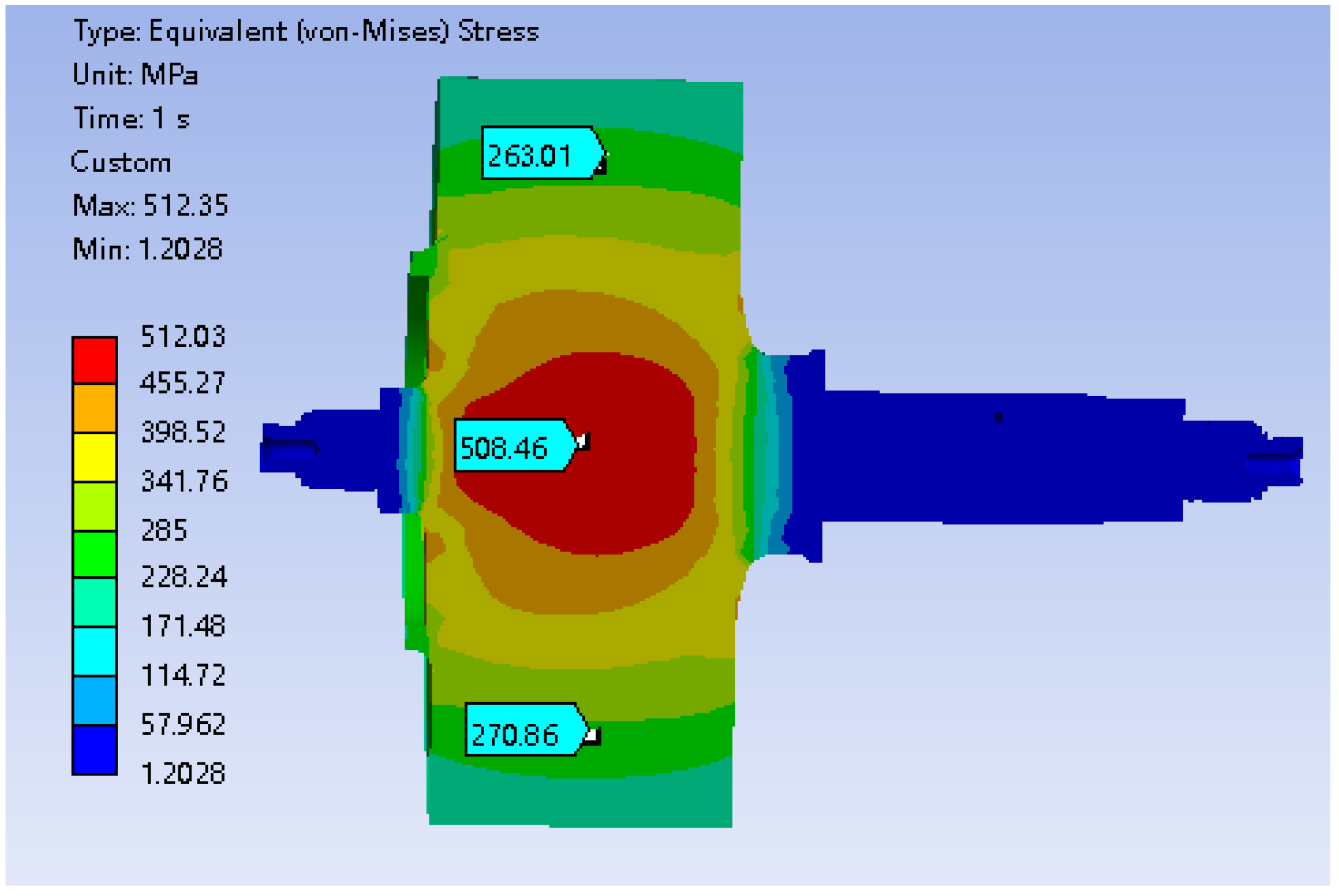
Firstly, the stress distribution of the flywheel body without internal defects was obtained through the finite element analysis. First, a model of the flywheel rotor was created based on its actual structure, resulting in a stress distribution cloud diagram, as shown in
Figure 18, where the maximum stress at the core reaches 512.0 MPa. To ensure that the results of this study are not limited to a specific structure but possess greater universality, the rotor structure was simplified to focus on the most critical energy storage portion.
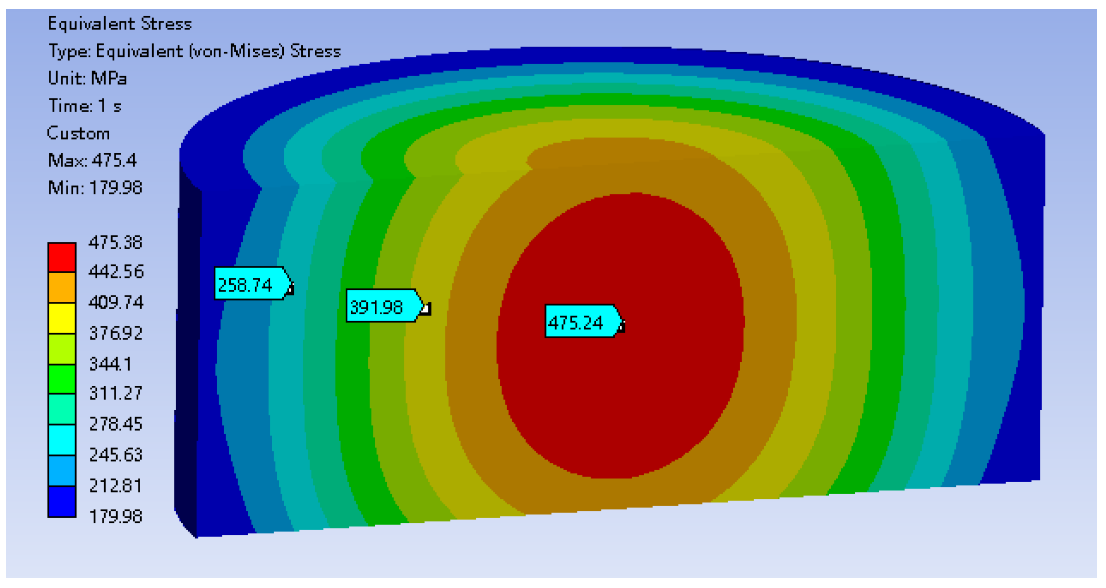
The stress distribution for this simplified model is simulated and illustrated in
Figure 19. The stress distribution of the simplified structure exhibits a similar trend to that of the actual rotor structure, indicating that the simplification is valid. The maximum stress is 475.4 MPa at the core, while the stress is minimum at 180.0 MPa at the outer diameter of the rotor.
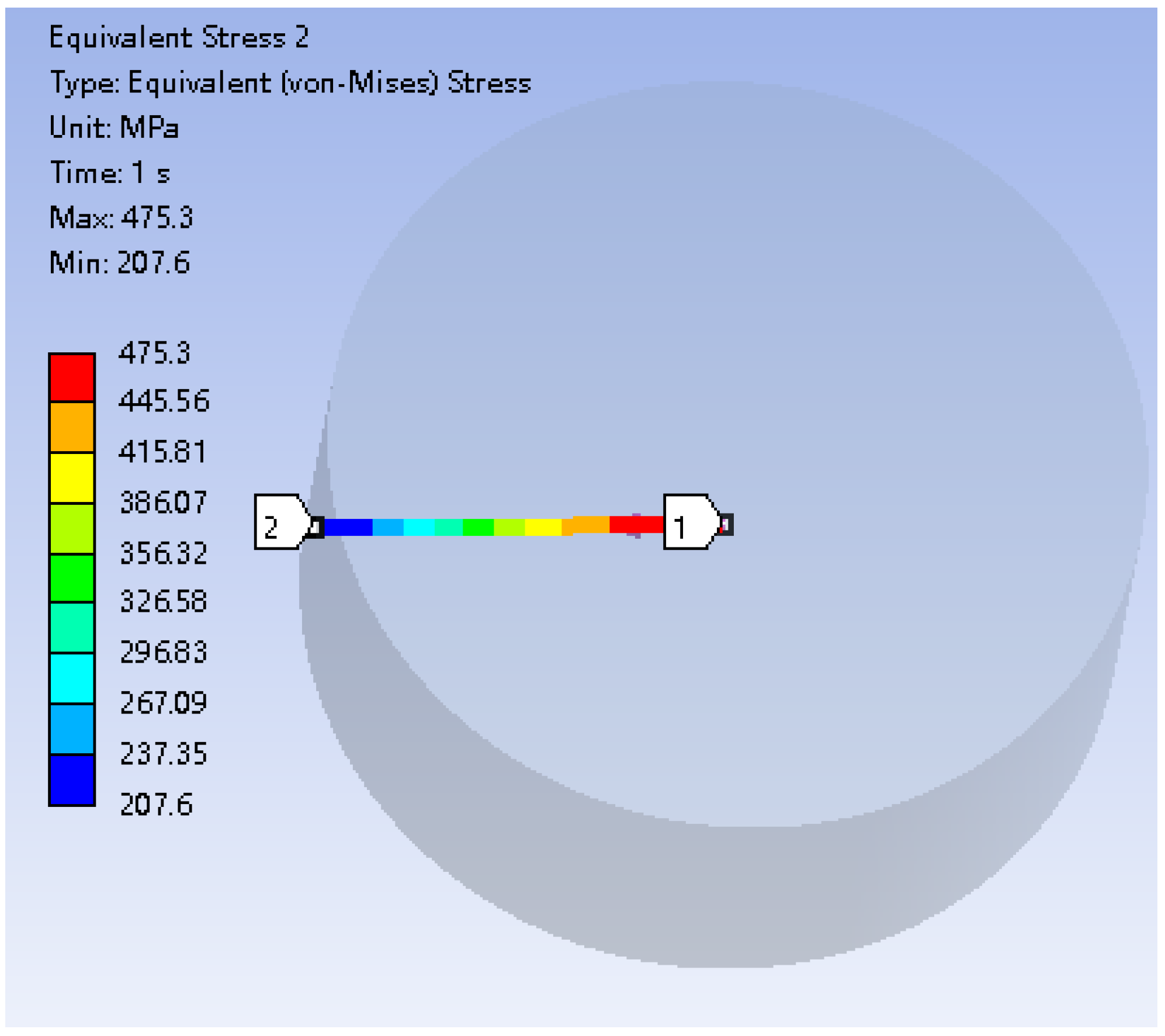
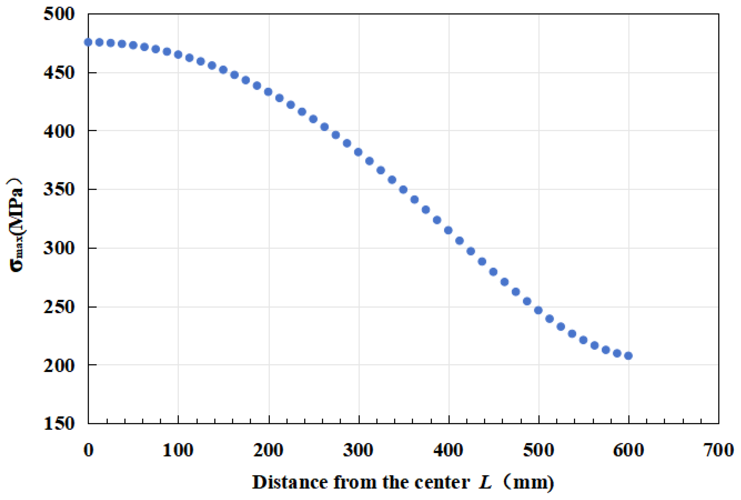
Section 4.1 calculated the maximum stress in the rotor core to be 459.7 MPa using Equation (7), which shows a discrepancy of only 3% compared with the finite element analysis results, thereby demonstrating the reliability of the obtained results. It is important to note that, compared with uniaxial stress, multiaxial stress can significantly affect the fatigue life of materials. Although many researchers have conducted studies on the prediction of multiaxial fatigue life, satisfactory predictive results have not yet been achieved. Therefore, this paper does not currently consider the effects of multiaxial fatigue stress. A path was established radially from the center to the outer diameter of the rotor, as depicted in
Figure 20. The stress variation along this path was analyzed, illustrating the radial stress distribution pattern of the rotor, as shown in
Figure 21.
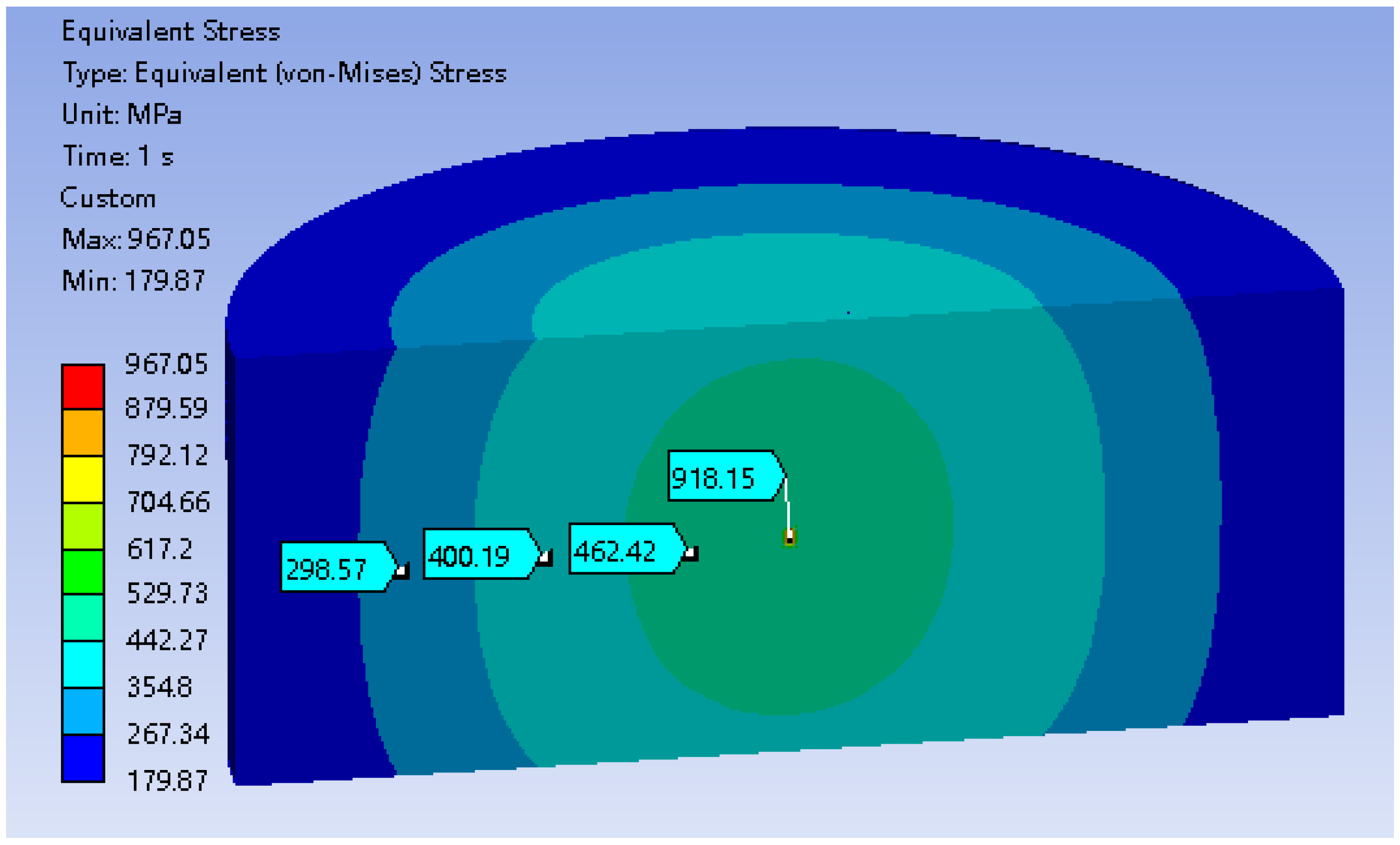
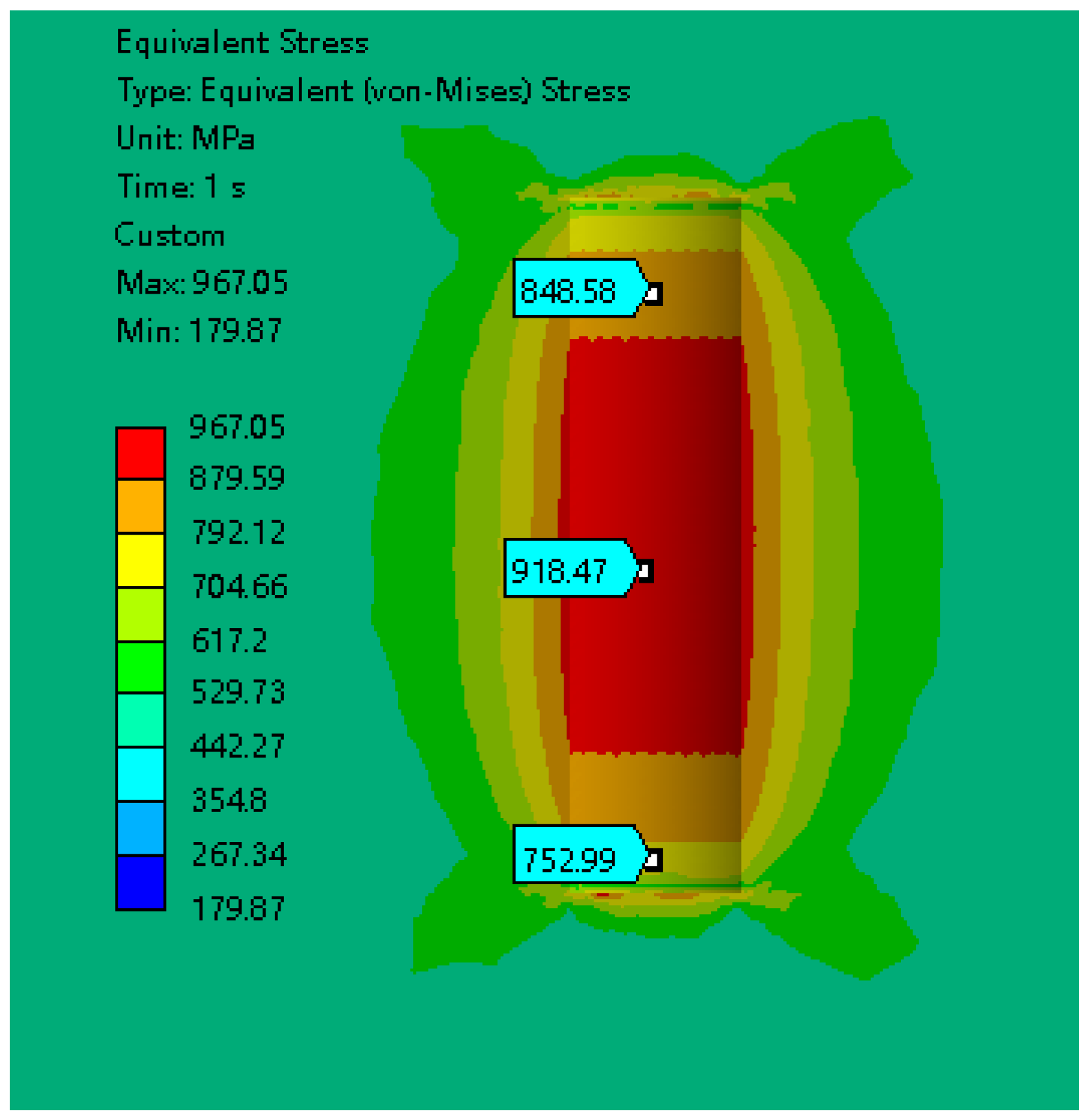
To investigate the impact of defect position on rotor stress and fatigue life, this study introduced an internal defect within the flywheel model—a cylindrical defect with a diameter of 10 mm and a height of 20 mm. For conciseness and clarity, this paper presents only the stress contour map when the defect is located at the center of the rotor. The results indicate that the presence of the internal defect increases the maximum stress in the flywheel to 967 MPa, with the highest stress being concentrated at the defect location. The overall internal stress contour map is shown in
Figure 22, while the stress contour map at the defect location is depicted in
Figure 23.
Figure 24 displays the relationship between the defect distance from the center (
Ld, in millimeters) and both maximum stress (in MPa) and predicted fatigue life (in cycles). It is evident from the graph that maximum stress decreases linearly as the defect distance
Ld increases, from approximately 950 MPa to 750 MPa, indicating that stress concentration diminishes as the defect moves further from the center. Conversely, the predicted fatigue life exhibits a significant nonlinear growth; as the defect location increases from 0 mm to 250 mm, the fatigue life grows from nearly 0 to over 5 million cycles.
This trend suggests that when defects in a structure are closer to the rotor center, the harm they cause, or the reduction in lifespan, grows exponentially. Therefore, in testing rotor forgings, particular attention should be paid to the forging quality at the core of the rotor. For defects near the rotor surface, a higher tolerance could be reasonably allowed. This poses a new research direction for current forging inspection standards: the evaluation criteria for rotor defects should consider their distance from the rotor center, a factor not currently accounted for in existing standards.
4.3. The Impact of Defect Size on Fatigue Life
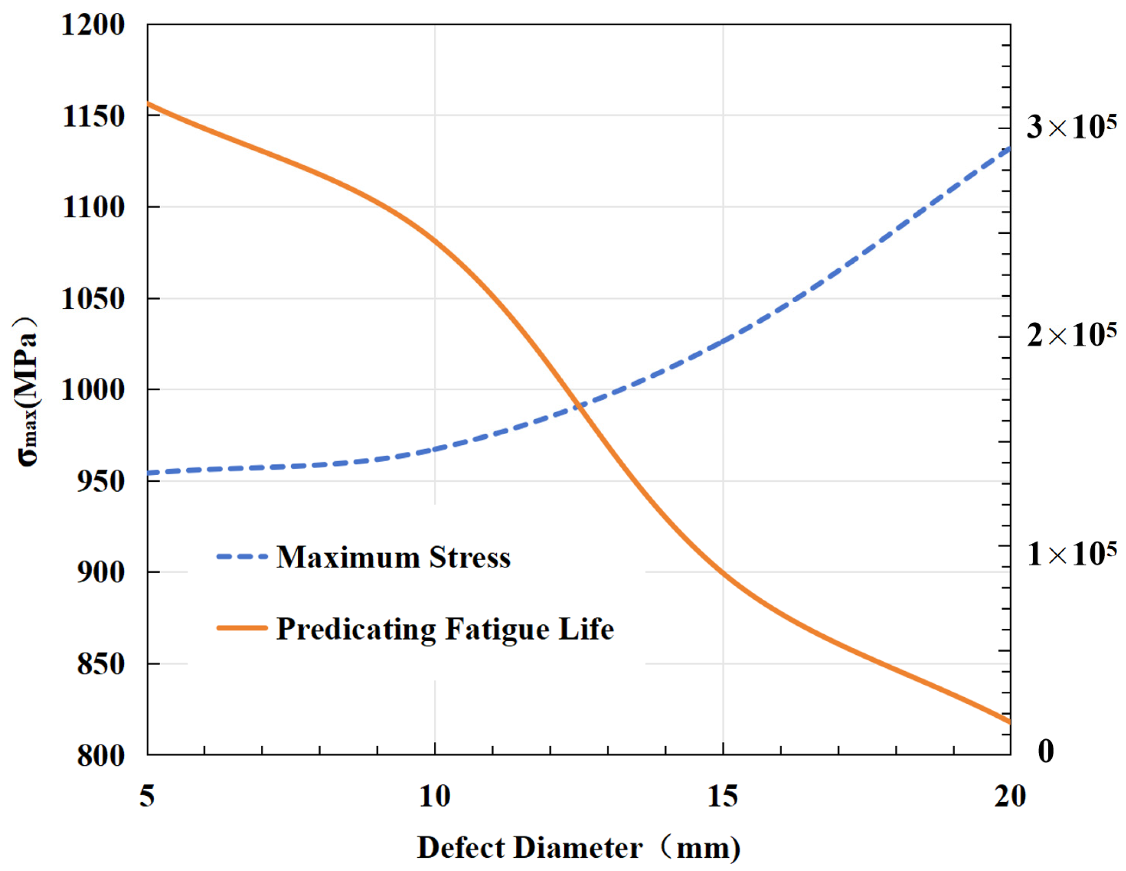
Figure 25 illustrates the impact of defect diameter on maximum stress and predicted fatigue life. The
x-axis represents the defect diameter in millimeters, the left
y-axis shows the maximum stress in MPa, and the right
y-axis indicates the predicted fatigue life in cycles.
As observed, with an increase in defect diameter, there is a linear decrease in maximum stress, while the predicted fatigue life exhibits an exponential decline. Specifically, as the defect diameter increases from 5 mm to 20 mm, the maximum stress drops from nearly 1150 MPa to around 900 MPa. Simultaneously, the predicted fatigue life reduces drastically from about 350,000 cycles to nearly 0.
This trend indicates that larger defects significantly weaken material load-bearing capacity and fatigue life due to greater stress concentration, accelerating the material fatigue process. These findings are crucial for understanding and preventing material failures, particularly in engineering design and safety assessments.
In summary, an increase in defect diameter has a significant negative impact on material fatigue life. Thus, in engineering applications, controlling and minimizing defects in materials is essential for enhancing the reliability and lifespan of structures.
4.4. Balancing the Relationship between Rotor Fatigue Life and Maximum Operating Speed from the Perspective of Benefits
When considering the relationship between rotor fatigue life and maximum operating speed, it is crucial to strike a balance from the perspective of benefits. Operating the rotor at higher speeds can increase productivity and efficiency, but it also poses a greater risk of fatigue failure due to increased stress and strain on the rotor material. Conversely, operating at lower speeds can prolong the fatigue life of the rotor but may result in a lower overall performance. It is important to clarify that, to ensure that the flywheel motor can achieve its rated power, the flywheel typically has a minimum operating speed n2, where n2 ≤ 0.5n1, with n1 being the maximum operating speed. The change in the rotor’s mechanical energy between the two rotational speeds represents the electrical energy that must be either discharged from or charged into the flywheel. Naturally, this process involves energy losses.
To achieve this balance, a comprehensive analysis needs to be conducted, taking into account factors such as the cost of replacing or repairing the rotor, the potential loss of production due to downtime, and the overall profitability of the operation. By carefully evaluating these factors, a decision can be made that optimizes both fatigue life and operating speed, maximizing the overall benefits while minimizing the risks associated with fatigue failure.
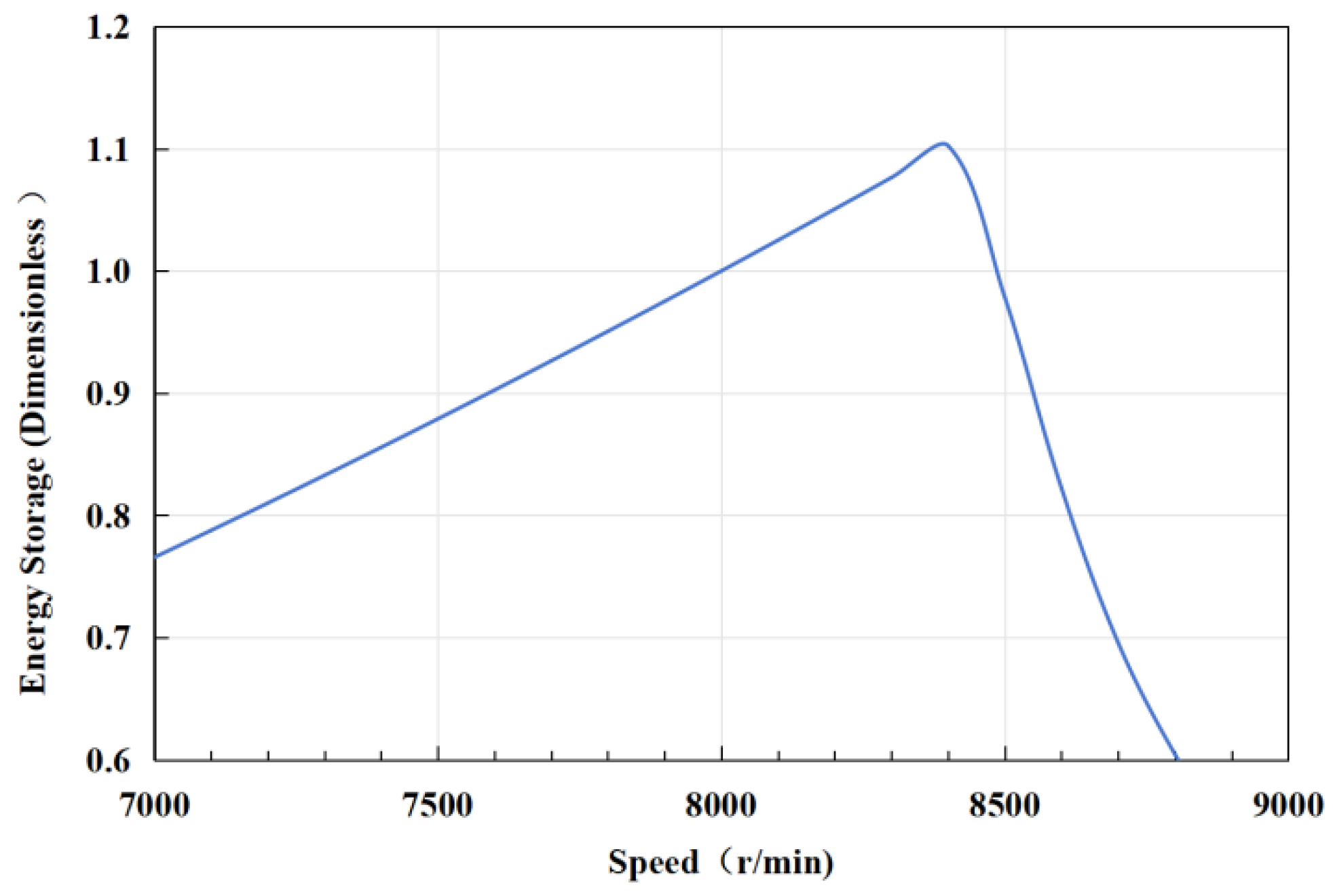
Figure 26 depicts the relationship between total stored energy and rotational speed throughout the entire life cycle of a flywheel energy storage prototype. Two specific points regarding the curve should be noted: first, the vertical axis represents dimensionless stored energy with the energy at 8000 rpm as the reference point; and second, considering various factors, the total cycle life of the flywheel rotor is capped at 1.5 million cycles. Due to this constraint, the curve peaks at the rotational speed corresponding to 150 cycles of rotor fatigue life, after which the total stored energy begins to decline with increasing speed. This underscores the critical influence of fatigue life on the total stored energy achievable by the flywheel rotor over its life cycle.
From the figure, it can be observed that as the rotational speed increases from 7000 rpm to approximately 8500 rpm, the total stored energy over the life cycle of the flywheel device shows a significant increasing trend, reaching a peak of around 1.1. However, as the speed continues to increase to 9000 rpm, the energy sharply decreases to below 0.8. In summary, the graph demonstrates an optimal point between total stored energy and rotational speed for the flywheel energy storage device, which in this case is approximately 8500 rpm.
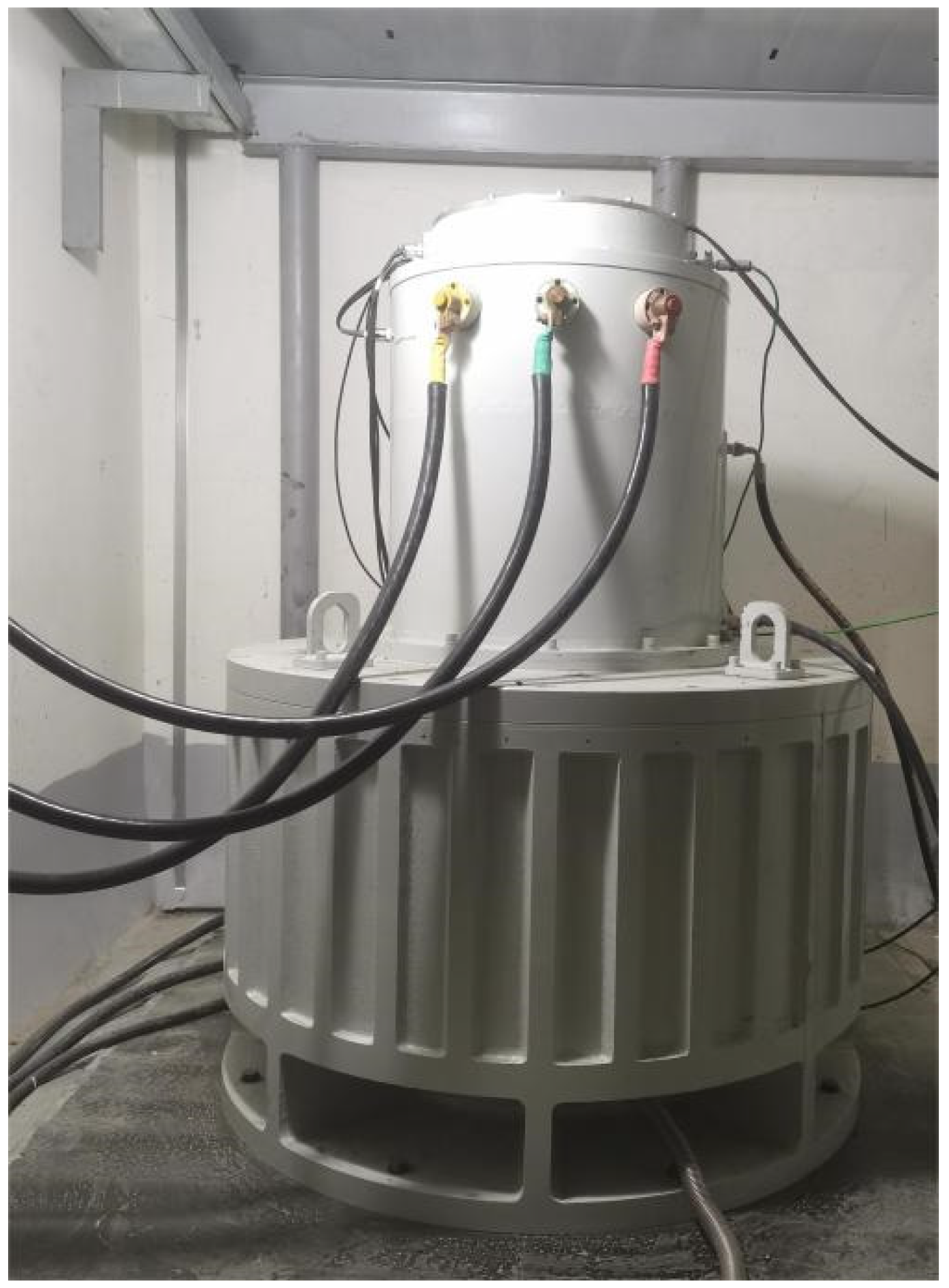
It is important to clarify that, although we ensured the flywheel unit we developed had an adequate safety factor through strength and fatigue analyses, implementing additional safety measures was still essential. We ensured the absolute safety of on-site personnel by placing the flywheel unit underground.
Figure 27 shows an on-site photograph of the flywheel unit. We also recommend that all flywheel units should adopt certain safety precautions during operation, such as establishing an independent enclosed space with protective features or placing the flywheel unit underground.
5. Conclusions
This study provides a detailed analysis of the fatigue life of flywheel energy storage rotors composed of 30Cr2Ni4MoV alloy steel. This study highlighted the material’s excellent mechanical properties, including high yield and tensile strengths, which are critical for the performance of flywheel rotors. Through comprehensive tensile and fatigue tests, the material was proven to be capable of enduring significant stress levels, making it suitable for high-stress applications such as energy storage rotors.
The calculation results of crack growth rates of 30Cr2Ni4MoV steel using the Paris formula align well with experimental data, confirming the accuracy of the model. This insight is crucial for predicting the service life of rotors under cyclic loading conditions.
A significant finding of the study is the impact of internal defects on the material’s fatigue life. The results showed that defects closer to the rotor’s center dramatically reduced fatigue life due to higher stress concentrations. Conversely, defects near the rotor surface had a less detrimental effect. This finding suggests that current forging inspection standards should be revised to account for defect location relative to the rotor center, enhancing the reliability of fatigue life predictions.
Furthermore, this study explored the relationship between rotor fatigue life and operational speed. It emphasizes the importance of balancing productivity and rotor durability. Operating at higher speeds increases stress and strain on the rotor, potentially reducing its fatigue life, while lower speeds may compromise overall performance. This research identified an optimal operational speed that maximized stored energy while maintaining acceptable fatigue life, providing a practical guideline for designing and operating flywheel energy storage systems.
In conclusion, this study underscores the importance of prudent design approaches and rigorous inspection standards for ensuring the long-term performance and safety of flywheel energy storage rotors composed of 30Cr2Ni4MoV alloy steel. The findings contribute to the development of more reliable and efficient energy storage solutions, supporting the integration of renewable energy sources into the power grid.
Author Contributions
Conceptualization, D.H. and X.D.; methodology, D.H. and X.D.; software, D.H.; validation, D.H.; formal analysis, D.H.; investigation, D.H. and X.D.; resources, W.L.; data curation, D.H.; writing—original draft preparation, D.H.; writing—review and editing, X.D. and H.C.; visualization, B.X. and H.Y.; supervision, X.D. and H.C.; project administration, B.X. and X.D.; funding acquisition, H.C. All authors have read and agreed to the published version of the manuscript.
Funding
This work was supported by the National Key R&D Program of China under Grant 2023YFB2406300; Major Science and Technology Projects in Inner Mongolia Autonomous Region; and Research on High Energy Storage Flywheel Rotor and Magnetic Bearing Technology 2020ZD0017-1.
Data Availability Statement
The original contributions presented in the study are included in the article, further inquiries can be directed to the corresponding author/s.
Acknowledgments
This work was supported by the National Key R&D Program of China under Grant 2023YFB2406300; Major Science and Technology Projects in Inner Mongolia Autonomous Region; and Research on High Energy Storage Flywheel Rotor and Magnetic Bearing Technology 2020ZD0017-1.
Conflicts of Interest
The authors declare no conflicts of interest.
References
- Mahmoud, T. Overview of energy storage systems in distribution networks: Placement, sizing, operation, and power quality. Renew. Sustain. Energy Rev. 2018, 91, 1205–1230. [Google Scholar]
- Asaad Yasseen, A.R.; Istvan, S.; Istvan, F. Selective Absorber Coatings and Technological Advancements in Performance Enhancement for Parabolic Trough Solar Collector. J. Therm. Sci. 2022, 31, 1990–2008. [Google Scholar] [CrossRef]
- Rahman, M.M.; Oni, A.O.; Gemechu, E.; Kumar, A. Assessment of energy storage technologies: A review. Energy Convers. Manag. 2020, 223, 113295. [Google Scholar] [CrossRef]
- Barra, P.H.; de Carvalho, W.C.; Menezes, T.S.; Fernandes RA, S.; Coury, D.V. A review on wind power smoothing using high-power energy storage systems. Renew. Sustain. Energy Rev. 2021, 137, 110455. [Google Scholar] [CrossRef]
- Dai, X.; Wei, K.; Zhang, X.; Jiang, X.; Zhang, K. A review on flywheel energy storage technology in fifty years. Energy Storage Sci. Technol. 2018, 7, 765–782. [Google Scholar]
- Rouse, J.P.; Garvey, S.D.; Cárdenas, B.; Hoskin, A.; Swinfen-Styles, L.; Xu, W. A case study investigation into the risk of fatigue in synchronous flywheel energy stores and ramifications for the design of inertia replacement systems. J. Energy Storage 2021, 39, 102651. [Google Scholar] [CrossRef]
- Liang, W.; Lou, M.; Zhang, C.; Zhao, D.; Yang, D.; Wang, Y. Experimental investigation and phenomenological modeling of fatigue crack growth in X80 pipeline steel under random loading. Int. J. Fatigue 2024, 182, 108169. [Google Scholar] [CrossRef]
- Pullen, K.R. 11-Flywheel energy storage. In Storing Energy, 2nd ed.; Elsevier Inc.: Amsterdam, The Netherlands, 2022. [Google Scholar]
- Gan, L.; Wu, H.; Zhong, Z. Multiaxial fatigue life prediction based on a simplified energy-based model. Int. J. Fatigue 2021, 144, 106036. [Google Scholar] [CrossRef]
- Milovanović, V.; Arsić, D.; Milutinović, M.; Živković, M.; Topalović, M. A Comparison Study of Fatigue Behavior of S355J2+N, S690QL and X37CrMoV5-1 Steel. Metals 2022, 12, 1199. [Google Scholar] [CrossRef]
- Li, J.; Li, C.W.; Qiao, Y.J.; Zhang, Z.P. Fatigue life prediction for some metallic materials under constant amplitude multiaxial loading. Int. J. Fatigue 2014, 68, 10–23. [Google Scholar] [CrossRef]
- Zhu, H.; Wu, H.; Lu, Y.; Zhong, Z. A novel energy-based equivalent damage parameter for multiaxial fatigue life prediction. Int. J. Fatigue 2019, 121, 1–8. [Google Scholar] [CrossRef]
- Nourian-Avval, A.; Khonsari, M.M. A new model for fatigue life prediction under multiaxial loadings based on energy dissipation. Int. J. Fatigue 2021, 151, 106255. [Google Scholar] [CrossRef]
- Moore, P.; Pargeter, A. Comparison of using the crack mouth displacement (CMOD) and load line displacement (LLD) methods in the determination of critical J integral in SENB specimens. Fatigue Fract. Eng. Mater. Struct. 2018, 41, 1997–2009. [Google Scholar] [CrossRef]
- Li, R.; Zhang, Y.; Chen, J.; Wang, M. Fatigue and Fracture Property of Turbine Rotor Steel-30Cr2Ni4MoV. Heilongjiang Electr. Power 2003, 25, 172–174. [Google Scholar]
- ASTM E399-09; Standard Test Methods for Linear-Elastic Plane-Strain fracture Toughness KI Cof Metallic Materials. ASTM: West Conshohocken, PA, USA, 2020.
- ASTM E1820-13; Standard Test Methods for Measurement of Fracture Toughness. ASTM: West Conshohocken, PA, USA, 2020.
- Liu, Y.; Wang, X.; Lel, X. Research on Heat Treatment Process of Ultra-pure 30Cr2Ni4MMoV Steel. Heat Treat. 2020, 35, 22–25. [Google Scholar]
- GB/T 4459.5-1999; Mechanical Drawings-Representation of Centre Holes. GB: Beijing, China, 1999.
- Hu, D.; Dai, X.; Li, W.; Zhu, Y.; Zhang, X.; Chen, H.; Zhang, Z. A review of flywheel energy storage rotor materials and structures. J. Energy Storage 2023, 74, 109076. [Google Scholar]
- Wang, J. Design and Charge-Discharge Control Research of High-Power Flywheel Energy Storage System Rotors. Master’s Thesis, North China Electric Power University, Beijing, China, 2019. [Google Scholar]
- Dai, X.; Jiang, X.; Zhang, K. Flywheel Energy Storage System Technology and Engineering Applications; Chemical Industry Press: Beijing, China, 2021. [Google Scholar]
Figure 1.
Frequency fluctuations—high frequency 24 h dataset components [
6].
Figure 1.
Frequency fluctuations—high frequency 24 h dataset components [
6].
Figure 2.
Internal structure diagram of the flywheel. 1. Lower support component; 2. rotor component; 3. motor component; 4. upper support component.
Figure 2.
Internal structure diagram of the flywheel. 1. Lower support component; 2. rotor component; 3. motor component; 4. upper support component.
Figure 3.
Material strength testing equipment.
Figure 3.
Material strength testing equipment.
Figure 4.
Tensile stress–strain curve of 30Cr2Ni4MoV steel.
Figure 4.
Tensile stress–strain curve of 30Cr2Ni4MoV steel.
Figure 5.
Crack propagation test specimen of 30Cr2Ni4MoV steel.
Figure 5.
Crack propagation test specimen of 30Cr2Ni4MoV steel.
Figure 6.
Crack propagation curve.
Figure 6.
Crack propagation curve.
Figure 7.
Comparison of crack propagation rates [
15].
Figure 7.
Comparison of crack propagation rates [
15].
Figure 8.
Relationship between fracture toughness and yield strength of 30Cr2Ni4MoV steel.
Figure 8.
Relationship between fracture toughness and yield strength of 30Cr2Ni4MoV steel.
Figure 9.
Fatigue testing equipment.
Figure 9.
Fatigue testing equipment.
Figure 10.
Technical drawing of the fatigue-testing specimen [
19].
Figure 10.
Technical drawing of the fatigue-testing specimen [
19].
Figure 11.
Fatigue testing status.
Figure 11.
Fatigue testing status.
Figure 12.
Fatigue life N/cycles.
Figure 12.
Fatigue life N/cycles.
Figure 13.
Mean fatigue life N/cycles.
Figure 13.
Mean fatigue life N/cycles.
Figure 14.
Comparison of model predictions with experimental results.
Figure 14.
Comparison of model predictions with experimental results.
Figure 15.
The effect of maximum stress on fatigue life when the stress amplitude is constant.
Figure 15.
The effect of maximum stress on fatigue life when the stress amplitude is constant.
Figure 16.
The effect of stress ratio on fatigue life when the maximum stress is constant.
Figure 16.
The effect of stress ratio on fatigue life when the maximum stress is constant.
Figure 17.
Stress state of a rotating disk [
20].
Figure 17.
Stress state of a rotating disk [
20].
Figure 18.
Stress contour map of the flywheel rotor.
Figure 18.
Stress contour map of the flywheel rotor.
Figure 19.
Stress contour map.
Figure 19.
Stress contour map.
Figure 20.
Stress distribution path.
Figure 20.
Stress distribution path.
Figure 21.
Stress variation curve.
Figure 21.
Stress variation curve.
Figure 22.
Stress contour map with an internal defect.
Figure 22.
Stress contour map with an internal defect.
Figure 23.
Stress contour map of defect location.
Figure 23.
Stress contour map of defect location.
Figure 24.
Effect of defect location on fatigue life.
Figure 24.
Effect of defect location on fatigue life.
Figure 25.
Effect of defect size on fatigue life.
Figure 25.
Effect of defect size on fatigue life.
Figure 26.
The relationship between total stored energy and rotational speed.
Figure 26.
The relationship between total stored energy and rotational speed.
Figure 27.
Flywheel energy storage unit placed underground.
Figure 27.
Flywheel energy storage unit placed underground.
Table 1.
Chemical composition and mass fraction of 30Cr2Ni4MoV steel (%).
Table 1.
Chemical composition and mass fraction of 30Cr2Ni4MoV steel (%).
| C | Si | Mn | P | S | Cr | Ni | Mo | V | Cu | Al |
|---|
| 0.30 | 0.039 | 0.24 | <0.005 | 0.0034 | 1.75 | 3.49 | 0.41 | 0.12 | 0.05 | <0.004 |
Table 2.
Mechanical properties of 30Cr2Ni4MoV steel.
Table 2.
Mechanical properties of 30Cr2Ni4MoV steel.
| E (GPa) | σ0.2 (MPa) | σb (MPa) |
|---|
| 206 | 992 | 1130 |
| Disclaimer/Publisher’s Note: The statements, opinions and data contained in all publications are solely those of the individual author(s) and contributor(s) and not of MDPI and/or the editor(s). MDPI and/or the editor(s) disclaim responsibility for any injury to people or property resulting from any ideas, methods, instructions or products referred to in the content. |
© 2024 by the authors. Licensee MDPI, Basel, Switzerland. This article is an open access article distributed under the terms and conditions of the Creative Commons Attribution (CC BY) license (https://creativecommons.org/licenses/by/4.0/).
