Article

Real-Time Energy Management Strategy for Fuel Cell Vehicles Based on DP and Rule Extraction

1
School of Electromechanical Engineering, Guangdong University of Technology, Guangzhou 510006, China
2
School of Mechatronics Engineering, Foshan University, Foshan 528225, China
3
Automotive Engineering Research Institute, BYD Co., Ltd., Shenzhen 518118, China
*
Author to whom correspondence should be addressed.
Energies 2024, 17(14), 3465; https://doi.org/10.3390/en17143465
Submission received: 13 June 2024 / Revised: 7 July 2024 / Accepted: 11 July 2024 / Published: 14 July 2024
(This article belongs to the Special Issue Energy Management and Control of Fuel Cell Hybrid Electric Vehicles)

Abstract

:
Energy management strategy (EMS), as a core technology in fuel cell vehicles (FCVs), profoundly influences the lifespan of fuel cells and the economy of the vehicle. Aiming at the problem of the EMS of FCVs based on a global optimization algorithm not being applicable in real-time, a rule extraction-based EMS is proposed for fuel cell commercial vehicles. Based on the results of the dynamic programming (DP) algorithm in the CLTC-C cycle, the deep learning approach is employed to extract output power rules for fuel cell, leading to the establishment of a rule library. Using this library, a real-time applicable rule-based EMS is designed. The simulated driving platform is built in a CARLA, SUMO, and MATLAB/Simulink joint simulation environment. Simulation results indicate that the proposed strategy yields savings ranging from 3.64% to 8.96% in total costs when compared to the state machine-based strategy.

1. Introduction

Hydrogen FCVs offer the benefits of high energy efficiency, zero pollution, and a wide range of fuel sources. However, as the sole power source in the power system, fuel cells have some defects, such as unstable power output, slow dynamic response, incapacity to effectively recover braking energy, and so on [1]. Therefore, FCVs typically employ fuel cells as their primary power source while battery or other auxiliary power sources form a hybrid power system to compensate for the shortcomings of fuel cells. EMS plays a pivotal role in the hybrid power system of FCVs. A good EMS can distribute the power of energy sources reasonably, thereby improving the system efficiency [2].
There are currently two main types of energy management strategies for FCVs. One is the rule-based strategy, and the other is the optimization-based strategy [3].
The rule-based EMS relies on the steady-state characteristics of the fuel cell, battery, and motor. It switches and controls the power distribution of the fuel cell hybrid power system according to the driver’s acceleration and braking requirements, as well as information about the overall vehicle and battery status. For example, by analyzing the characteristics of a fuel cell to determine its high-efficiency region, the system limits its output power to remain in the high-efficiency region, thus obtaining good fuel economy [4]. Based on the characteristics of the battery and supercapacitor, Wang et al. [5] formulated an EMS using a finite-state machine. Song et al. [6] utilized wavelet transform to extract the load requirements of low frequency as a primary component, successfully alleviating the fluctuation of fuel cell power. Wang et al. [7] introduced a power flow control method for fuel cell power systems based on fuzzy logic controller, considering the cost and lifetime of fuel cells. Rule-based EMSs are simple and easy to implement, and as such are widely used in practical production vehicles. However, their dependence on engineers’ experience, preset driving conditions, and hybrid power system structure restricts their applicability to specific working environments, resulting in poor portability [8,9].
The optimization-based strategy can be further categorized into two types: global optimization and real-time optimization. The EMS based on global optimization is an approach that prioritizes fuel economy or life as the optimization objective. It seeks to solve the global optimal power allocation trajectory within predefined cycles. This type of EMS mainly includes dynamic programming algorithms [10], game theory [11], genetic algorithms [12], and particle swarm optimization [13]. Geng et al. [14] put forward an EMS that integrates DP and equivalent consumption minimization strategy and optimized the equivalent factor by employing an iterative approach. Simulation results indicate a significant improvement in fuel economy under the NEDC cycle, with a 19.9% improvement compared to the rule-based strategy. Wei et al. [15] introduced rapid speed planning and EMS based on layered convex optimization for FCVs through multi-signal lamp scenarios, which can reduce hydrogen consumption by 45%.
Real-time optimization strategies can effectively decompose complex global optimization problems into several local optimization problems, thereby reducing the computational burden and decreasing the reliance on operating conditions information. Currently, this form of EMS mainly includes Pontryagin’s Minimum Principle (PMP) [16], the Equivalent Consumption Minimization Strategy (ECMS) [17], and learning-based EMS [18]. Song et al. [19] put forward a sub-optimal EMS based on PMP, taking into account both economic and endurance. This strategy effectively enhances the fuel cells’ life. Jeoung et al. [20] used a data-driven approach to analyze the SOC under different driving conditions and proposed a PMP-based energy management strategy based on it. A real-time EMS based on fuzzy adaptive ECMS is proposed by Wang et al. [21]. Compared with the other three methods, the fuzzy adaptive ECMS reduces fuel consumption by 0.46–5.91% through the simulation of two typical cycles. In complex and variable cycles, the equivalent factor will change correspondingly, but many ECMS energy management strategies choose a fixed equivalent factor, which makes the solution inaccurate. Therefore, an improved ECMS method—adaptive equivalent consumption minimization strategy (A-ECMS)—is developed based on this problem [22,23]. Jia et al. [24] proposed a learning-based model prediction (L-MPC) EMS. BiLSTM is employed for accurate prediction at the speed prediction layer, and then the TD3 algorithm is used at the energy management layer to solve the control sequence. It was demonstrated by simulation that the effects of L-MPC were all superior to those of MPC or TD3 alone.
The EMS based on global optimization, although capable of achieving theoretical optimal control, is limited by its higher computational complexity and the requirement for advanced knowledge of operating conditions. It is not practical for real-world driving scenarios and is typically used for offline optimization. On the other hand, the EMS based on real-time optimization, while more computationally efficient, typically achieves suboptimal results compared to the global optimization strategy.
To solve the problem of the rule-based control strategy not being effective and the global optimization algorithm not being applicable in real-time, the main contributions of this paper can be summarized as follows: (1) a multi-objective EMS for the commercial FCV based on DP and rule extraction is proposed, and (2) fuel cell output rules are extracted from the results solved by the DP using BPNN and a rule base is created.
The remainder of this paper is structured as follows. First of all, the hybrid energy source model is built in Section 2, including the configuration selection of the hybrid energy source, the battery Thevenin model, the fuel cell model, and the demand power model. In Section 3, the DP algorithm is employed to address the energy management problem of hybrid FCV. In Section 4, a real-time EMS based on rule extraction is designed. Section 5 presents extensive simulation outcomes to affirm the performance and applicability of the proposed approach. Finally, the conclusion is summarized in Section 6.

2. Hybrid Energy Source Model

2.1. Configuration of Hybrid Energy Source

In this paper, the configuration of a hybrid energy source composed of a semi-active fuel cell and a battery is studied. The form of the connection is shown in Figure 1.
The ‘electric–electric hybrid’ combination of fuel cell and battery is a simple, efficient, and structurally stable hybrid power system. In this system, the fuel cell primarily supplies the fundamental power needs of the vehicle, while the battery provides peak power and transient power and recovers braking energy. The advantages of this combination lie in reducing the power fluctuation of fuel cells, extending the service life of fuel cells, saving hydrogen fuel, and improving the overall economy of the vehicle.

2.2. Battery Thevenin Model

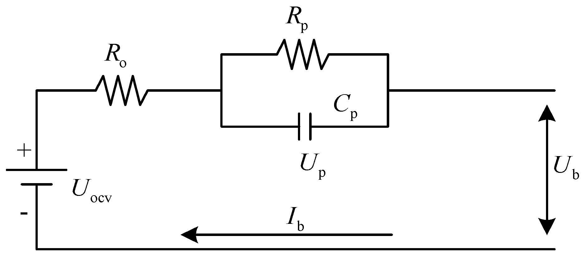
The Thevenin model, among various equivalent circuits, serves the dual purpose of reflecting the battery’s response to the load and describing its polarization. The equivalent circuit diagram is shown in Figure 2.
The equivalent circuit of the Thevenin model is analyzed, and Kirchhoff’s circuit laws are as follows:
U b = U o c v U p I b R 0 U . p = U p R p × C p + I b C p P b = I b U b
where U o c v , U p , and U b are the open circuit voltage, instantaneous polarization voltage, and output voltage of the battery, I b denotes the current of the battery, P b denotes the output power, R 0 is the internal resistance of Ohm of the battery, R p is the internal resistance of polarization, and C p is the battery polarization capacitance.
The charge state BSOC of the battery is calculated by the time-of-ampere integral method as follows:
B S O C t = B S O C ( t 0 ) I b t d t Q bat
where B S O C t 0 represents the initial charge state of the battery and Q bat denotes the capacity of the battery. The battery parameters used in this paper are shown in Table 1.

2.3. Fuel Cell Model

In general, there are three types of voltage losses in proton exchange membrane fuel cell (PEMFC) output voltage: U act activation polarization voltage loss, U ohm polarization voltage loss, and U co concentration proton exchange membrane fuel cell voltage loss. PEMFC monomer output voltage is calculated as follows:
E cell = E Nernst U act U ohm U co
where E Nernst is thermodynamic electromotive force.
The actual voltage of general PEMFC monomers is only about 0.7 V. To achieve the high voltage and high power required for automobiles, multiple monomers need to be connected in series to form a fuel cell stack. The voltage of the fuel cell stack is calculated as follows:
U fc = n cell E cell
where n cell is the number of monomers in the stack.
The hydrogen consumption rate of fuel cell m f c can be calculated as follows:
m ˙ f c = M H 2 n cell I f c 2 F
I f c = P f c U fc
where M H 2 denotes the molar mass of hydrogen, I f c denotes the stack current, F denotes the Faraday coefficient, and P f c denotes the power of the fuel cell.
Frequent load changes, start-stop times, and low- and high-load operation all affect fuel cell life [25]. This paper uses the widely used degradation model to quantitatively describe the relationship between fuel cell degradation and operating conditions [26,27,28]. The model takes the output voltage attenuation as the index, and the rated voltage drop of 10% is regarded as the end of life. The voltage degradation percentage of the fuel cell D ˙ f c can be formulated as follows:
D ˙ f c = k p ( k 1 t 1 k 2 n 2 k 3 t 2 k 4 t 3 )
where k p is the correction coefficient; t 1 , n 2 , t 2 , and t 3 are low load running time, start-stop time, duration of load variation, and high load running time, respectively; k 1 , k 2 , k 3 , and k 4 are degradation coefficients; and the values of the parameters are shown in Table 2. The fuel cell parameters used in this paper are shown in Table 3.

2.4. Motor Model

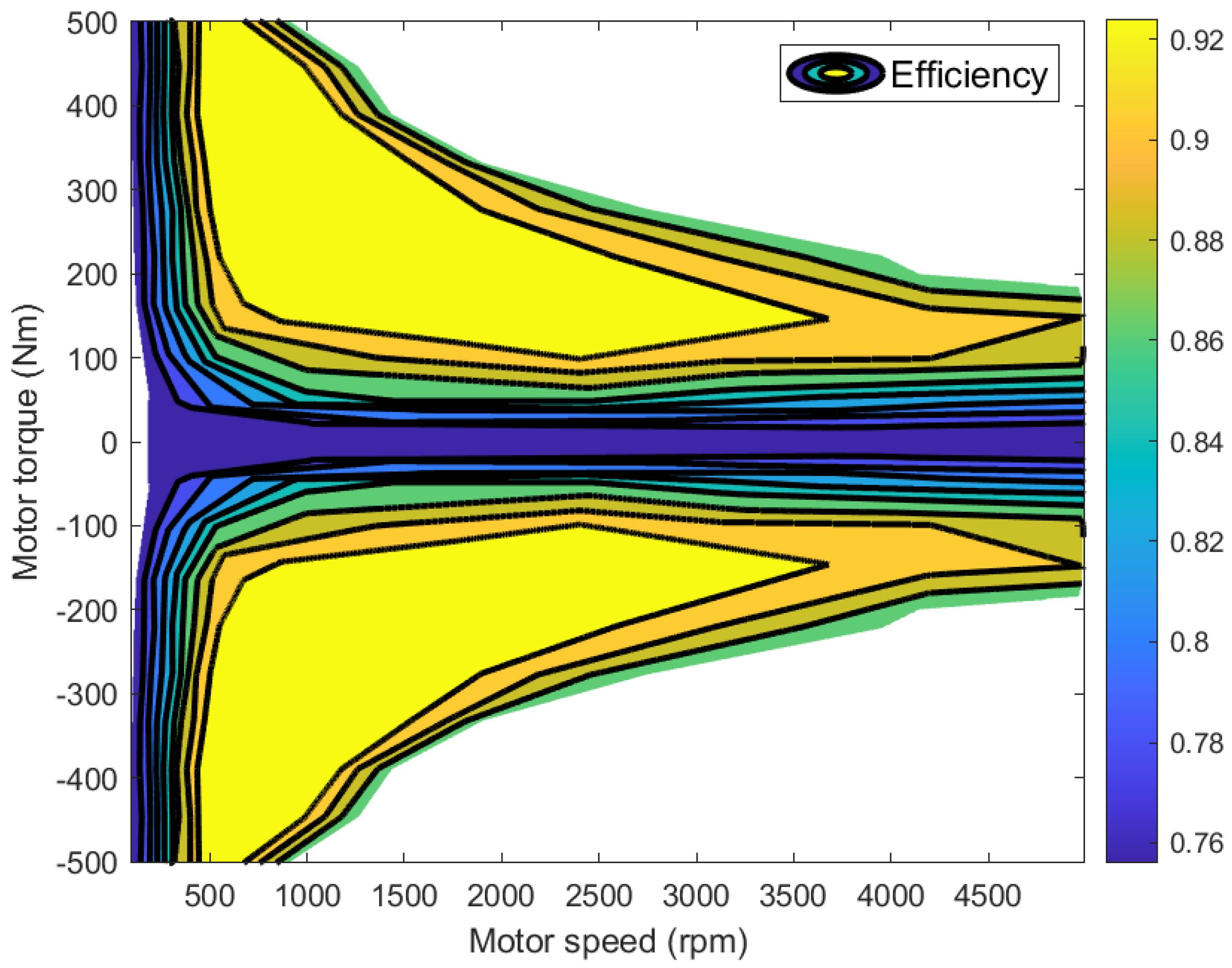
The electric motor, serving as a pivotal power component in FCVs, transforms the electrical energy produced by the fuel cell and battery into mechanical energy to propel the vehicle. Additionally, it can recover energy during braking, further enhancing the vehicle’s economy. In this paper, a motor with a rated power of 65 kW is used, and its efficiency map is shown in Figure 3. The efficiency of the motor can be expressed as follows:
η m = f ( n m , T m )
where η m denotes the motor efficiency, n m is the motor speed, and T m is the motor torque.

2.5. Power Demand Model

In this paper, the object of study is the energy management optimization problem, so only the longitudinal vehicle dynamics model needs to be considered. Based on the vehicle longitudinal dynamics model, the power demand P d of the motor can be formulated as follows:
P d = v ( m g f   cos α + C D A v 2 21.15 + m a   sin α + δ m d v d t ) 3600 η t η m  
where v is the velocity, m is the mass of the vehicle, g is the gravitational acceleration, f is the rolling resistance coefficient, α denotes the slope of the road, C D represents the air resistance coefficient, A denotes the area facing the wind, δ is the conversion coefficient of the vehicle’s rotational mass, η t is the transmission efficiency, and η m denotes motor efficiency. The key parameters of fuel cell commercial vehicle are listed in Table 4.

3. EMS of Fuel Cell Hybrid Energy System Based on DP Algorithm

EMSs in FCVs aim to make full use of the advantages of the fuel cell and battery, enabling these energy sources to collaborate synergistically. As a result, the FCV can offer good comprehensive performance. In this paper, the EMS of the fuel cell hybrid energy source is solved by the DP algorithm, and the optimal state trajectory and control sequence of the FCV are obtained.

3.1. DP Algorithm Implementation

Taking the total cost of FCV m c o s t as the objective function, the total cost is composed of the equivalent hydrogen cost and the cost of fuel cell degradation. The expression for the total cost is as follows:
m ˙ c o s t = C H 2 m ˙ H 2 e q u + C f c D ˙ f c
where C H 2 = U S D 4 / k g is the hydrogen price and C f c = U S D 93 / k W is the price of fuel cell [29]. m H 2 e q u is the equivalent hydrogen consumption of FCV, which consists of the direct hydrogen consumption of fuel cell m ˙ f c and the equivalent hydrogen consumption of battery m ˙ B a t .
m ˙ H 2 e q u = m ˙ f c + κ   m ˙ B a t
where κ is the correction coefficient of equivalent hydrogen consumption.
There are an infinite number of energy management control sequences for FCVs under known driving cycles, and the core of the DP algorithm is to find the optimal control sequence to minimize the total cost:
J = min k = 1 n [   C H 2 m ˙ H 2 e q u k + C f c D ˙ f c k ]
The state of charge (SOC) and polarization voltage of the fuel cell V p are selected as the state variables, and the control variable is the output power of the fuel cell P f c . The state transition equation is calculated as follows:
V p k + 1 = V p k e t k + 1 t k R p C p + V o c v , k V p , k V o c v , k V p , k 2 4 P b , k R 0 , k 2 × R 0 , k R p 1 e t k + 1 t k R p C p S O C k + 1 = S O C k V o c v , k V p , k V o c v , k V p , k 2 4 P b , k R 0 , k 2 R 0 , k Q bat t k + 1 t k
Each component of the hybrid electric power system in the FCV operates within a specific range. Therefore, when solving the DP, it is essential to constrain the working parameters based on the actual operation characteristics of these components:
S O C m i n S O C S O C m a x U p _ m i n U p U p _ m a x P f c _ m i n P f c P f c _ m a x
The DP algorithm divides the problem into several sub-problems and solves the original problem by solving the sub-problem’s optimal solution. For the EMS of FCVs, the time can be discretized based on driving cycles. As such, we set each second to a step size. At the same time, state variables such as battery SOC and battery polarization voltage also need to be discretized based on its operating range (upper and lower limits). The DP solution process can be divided into two steps. The first step is the backward-solving process, which starts from the final stage of the cycle and works backward to the first stage of the cycle. The second step is the forward deduction process, which begins from the optimal cost function and control variable of the first stage and gradually deduces the state at the final stage. This is done to determine the optimal trajectory of control variable changes, thereby finding the minimum total cost for the entire operating conditions.

3.2. DP Result and Analysis

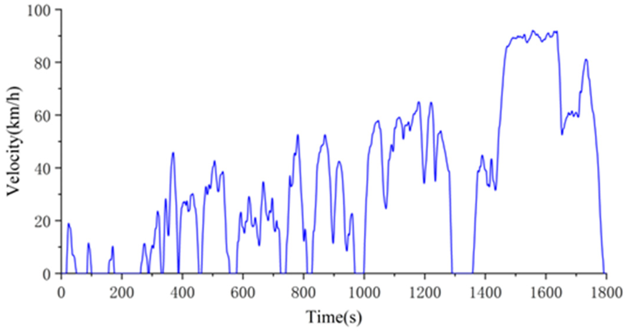
The research object of this paper is a light commercial vehicle, so the CLTC-C driving cycle was chosen as the simulation condition, which is specifically designed for testing light commercial vehicles. The velocity information of CLTC-C is shown in Figure 4.
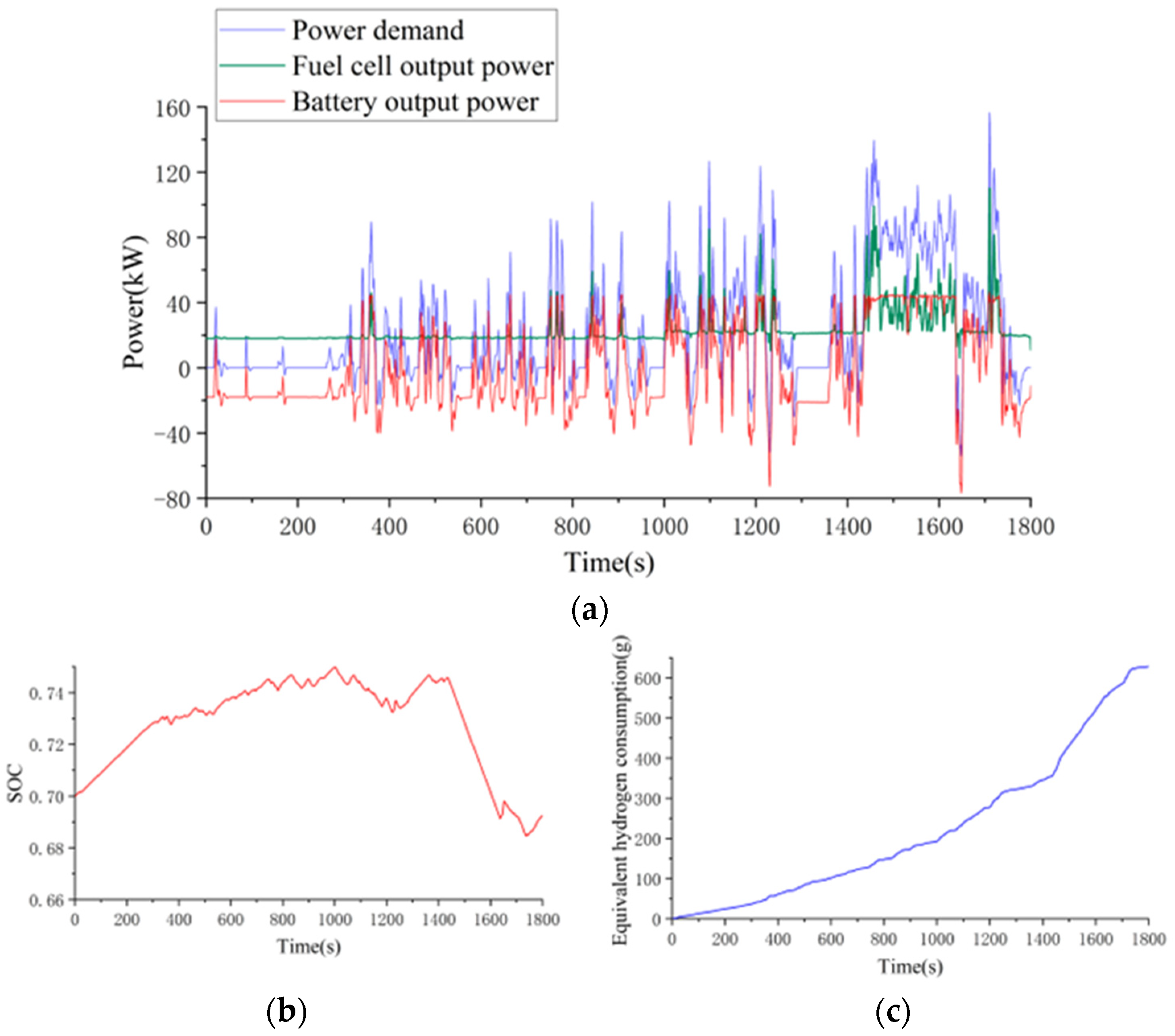
The DP algorithm is employed to solve the EMS under the CLTC-C cycle, and the result is shown in Figure 5.
Figure 5a illustrates the demand power and the power distribution of the fuel cell and the battery under the CLTC-C cycle. As the main energy source, the fuel cell bears the majority of the required power. The curve shows that the fuel cell keeps a steady output when the demand power is low while the vehicle is running. During rapid acceleration and high-power demand scenarios, the battery provides supplementary peak power. This helps maintain a stable output from the fuel cell and contributes to prolonging the fuel cell’s life. Figure 5b displays the SOC variation curve of the battery. The DP algorithm controls the output power of the fuel cell by global optimization and keeps the final SOC within the preset range. In the first 1400 s of the CLTC-C cycle, the power demand is relatively small and the braking deceleration is frequent, so the battery is charged most of the time. In the 1400 s to 1800 s, there is a relatively high power demand, and the battery needs to provide a substantial amount of power output. Consequently, the SOC exhibits a decreasing trend during this time frame. Figure 5c shows the equivalent hydrogen consumption curve. The equivalent hydrogen consumption of the CLTC-C cycle is 628.5 g, and it generally increases over time. However, it exhibits negative values due to the battery’s energy recovery function, resulting in localized decreases in equivalent hydrogen consumption.

4. Real-Time EMS Based on Rule Extraction

Although the fuel cell EMS based on DP can obtain a control sequence that minimizes total cost, it cannot be applied in real time because of the need to know the entire cycle and the extensive computational requirements. However, the off-line calculation results of CLTC-C EMS based on the DP algorithm can be used as the database. Therefore, the real-time EMS is designed based on the extraction of rules for the fuel cell. These rules are derived by analyzing the relationships among power demand, drive motor torque, vehicle speed, and fuel cell output power.

4.1. Extraction of Fuel Cell Power Output Rules

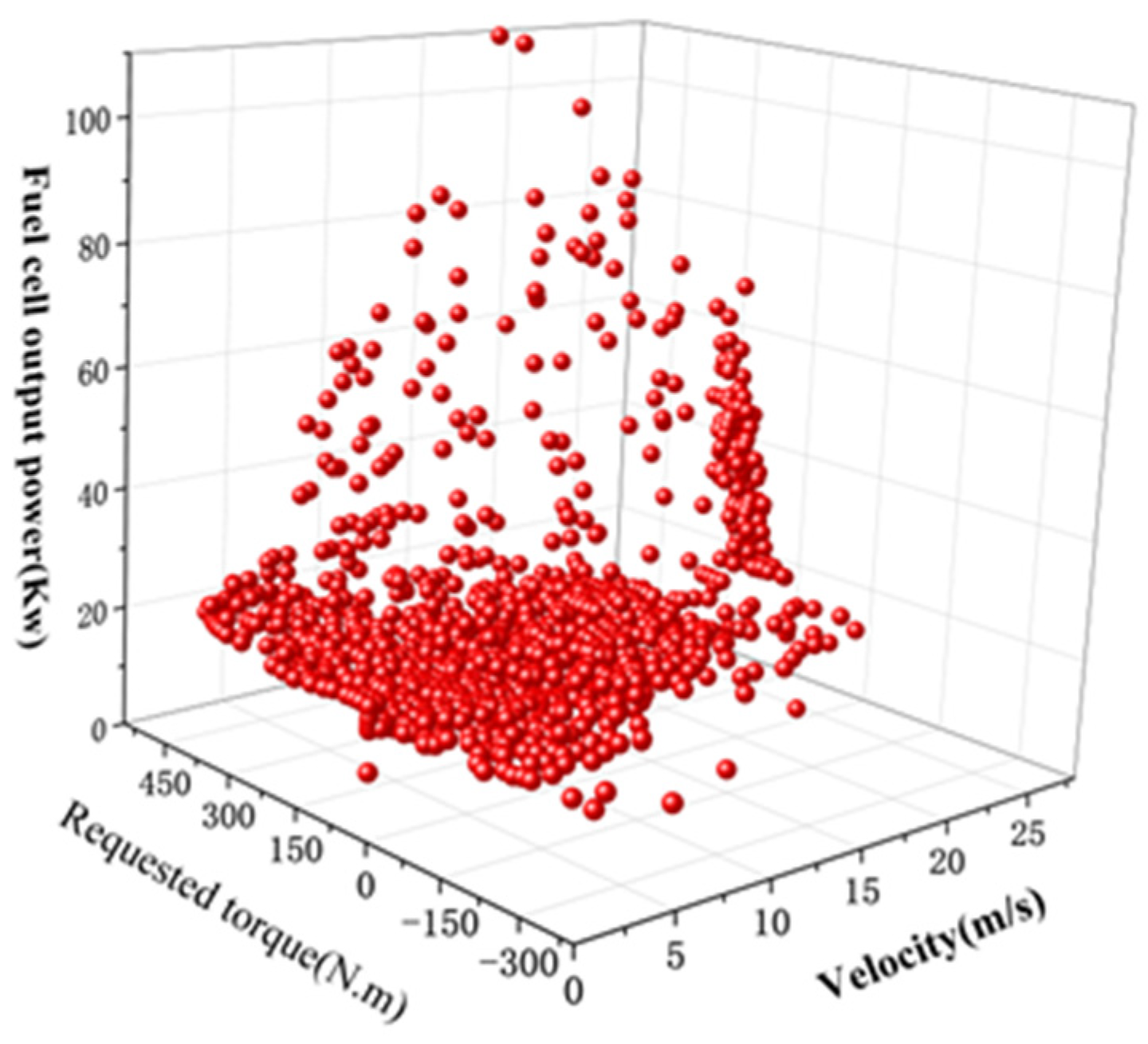
Observing Figure 5a, it becomes evident that there is a discernible relationship between the fuel cell output power and the power demand. At low speeds, the fuel cell maintains a steady power output, while at high speeds, the fuel cell output fluctuates with the power demand. Thus, there is also a certain rule between the output power of fuel cells and vehicle speed. The research object of this paper is a single-motor FCV, and there is a deterministic relationship between the power demand, the requested torque of the motor, and the motor speed (vehicle speed). Therefore, in order to describe the fuel cell output rule more accurately, this paper mainly analyses the regular relationship between the fuel cell output power, the requested torque of the motor, and the speed of the vehicle, instead of only analyzing the relationship between the fuel cell output power and the power demand.
As can be seen from Figure 6, the output power of the fuel cell shows a certain regularity with the change of the current speed and the requested output torque, meaning it can be determined based on the current vehicle speed and the requested output torque. Each scatter corresponds to a relationship between vehicle speed, requested output torque, and fuel cell output power. The DP algorithm cannot be directly used in real-time control systems because of its long computation time. In this paper, the backpropagation neural network (BPNN) based on the results obtained from the DP algorithm is used to train the point in the scatter plot of the corresponding relationship between vehicle speed, requested output torque, and fuel cell output power shown in Figure 6; thereby, the rule library of fuel cell output power within the vehicle’s performance range is obtained.
To solve the fuel cell EMS problem based on the DP algorithm, it is necessary to find the optimal fuel cell power output scheme for the known typical cycles so as to minimize the accumulative equivalent hydrogen consumption of the vehicle in the whole cycle. Therefore, the output power of the fuel cell P f c is chosen as the output of neural network training. The power of the battery is determined by the relationship between the power demand and the fuel cell output power. We select the current vehicle speed v a and the requested torque of the drive motor T m _ r e q as the input signal. After determining the input signal, a double hidden layer BPNN with nine neurons is used to train the input and output data based on the results obtained from the DP solution, as shown in Figure 7.
In this paper, the speed and motor torque of the fuel cell commercial vehicle in the range of performance are discretized and used as input signals for a trained neural network. The output signal corresponds to the respective fuel cell output power. This process results in a rule library for fuel cell output power, representing the power allocation scheme between the fuel cell and the battery. The rule library after surface fitting is shown in Figure 8.

4.2. EMS Based on Control Rule Extraction

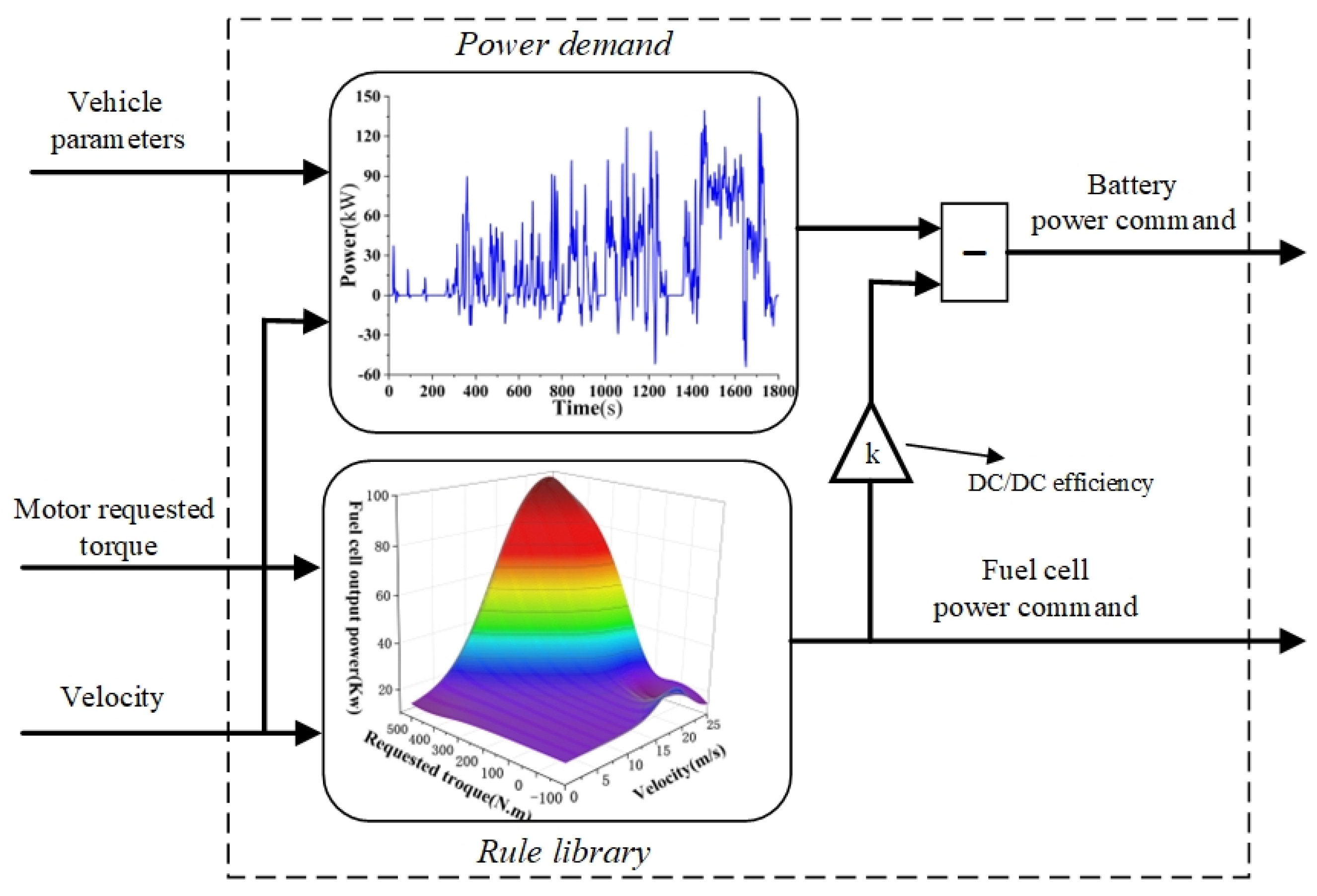
According to the power output rule of the fuel cell, a real-time EMS is constructed according to the method of Figure 9. First of all, the required torque of the motor is obtained through the motor controller. Next, according to the requested torque of the drive motor and the current vehicle speed, the fuel cell outputs the corresponding power according to the work point of the fuel cell output rule library in Figure 8. At the same time, the power demand is calculated according to the vehicle parameters and the current speed. While the fuel cell provides the energy, the power output of the battery is determined according to the required power of the vehicle and the output power of the fuel cell; the battery replenishes energy when the fuel cell output is insufficient to meet the drive demand or stores excess energy when the fuel cell output exceeds the demand.

5. Simulation Platform Construction and Experimental Verification

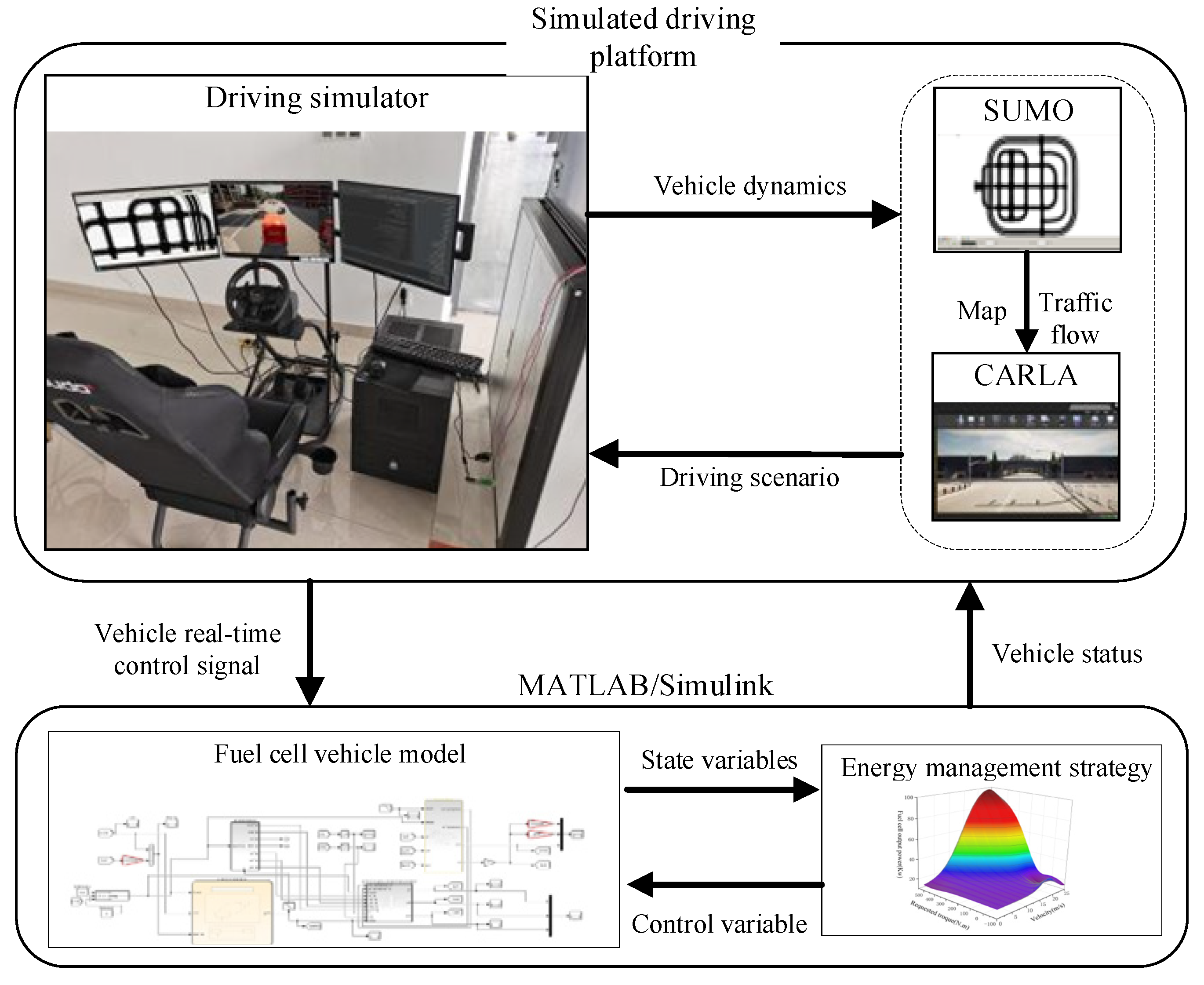
Based on the EMS designed above, which is based on DP and rule extraction, a joint simulation software platform is built using CARLA, SUMO, and MATLAB/Simulink. This platform is used for the real-time application experiment of the EMS on the hardware simulator platform and high-performance computer.

5.1. The Joint Simulation Platform

For the research on EMS for FCVs, the joint simulation environment of CARLA and SUMO provides an effective driving simulation platform to validate and evaluate the designed control strategy. The simulation platform is built as shown in Figure 10.
Firstly, based on the previous chapters, the comprehensive vehicle model and EMS program of FCVs were established through MATLAB/Simulink. In the CARLA simulated driving environment, we configured the relevant performance parameters based on the vehicle model. The simulator includes components such as seats, throttle, and brakes to replicate the actual driving experience of a vehicle. By operating the simulator, you can control the FCV’s movement within the CARLA-simulated driving environment. The main role of SUMO in the simulation framework is to simulate traffic flow by interacting with CARLA to generate and simulate the behavior of other vehicles and pedestrians and to evaluate the real-time EMS performance of the FCV in a real traffic environment. The driving simulation platform converts the vehicle control signals into input state variables, including motor-requested torque and the current vehicle speed, according to the vehicle model. The EMS program, based on MATLAB/Simulink, is then utilized to calculate the real-time control variable, which is the fuel cell output power. There are two main performance indicators that are evaluated in the simulation:
  • Hydrogen consumption: It represents the fuel economy of the FCV. Due to the potential inconsistency in the final SOC of the battery with different strategies, the comparative analysis is mainly performed using the equivalent hydrogen consumption;
  • Fuel cell degradation: It represents the lifetime of the fuel cell system. This indicator can assess the long-term stability and reliability of the EMS in the fuel cell system.

5.2. Simulation Result and Analysis

In order to verify the real-time control effect of the designed EMS, three driving scenarios, namely urban cycle, suburban cycle, and highway cycle, were simulated based on the above-mentioned simulation environment to verify the performance of the EMS in different situations.
1
Urban cycle:
The driving conditions of urban roads are typically complex, with numerous features such as dense intersections, traffic lights, and traffic congestion. Simulation scenarios and driving routes of the urban cycle are shown in Figure 11a. In this environment, vehicles often maintain a low average speed, typically ranging from 15 to 20 km/h, with a maximum speed usually not exceeding 40 km/h. At the same time, vehicles on urban roads will often encounter idle moments, such as when stuck in traffic jams or waiting at traffic lights. Figure 11b illustrates the speed changes along a 3.22 km urban road. The total travel time is 605 s, with a mean velocity of 19.14 km/h and the highest velocity reaching 36.96 km/h.
2
Suburban cycle:
As a transition between the urban and the suburban road, the suburban driving cycle exhibits certain unique characteristics. Simulation scenarios and driving routes of the suburban cycle are shown in Figure 12a. On suburban roads, the vehicle’s speed is relatively high, and speed limits are more relaxed. The average speed of a vehicle is usually between 40 and 80 km/h. Due to the vast expanse of suburban areas and lower population density, vehicles experience fewer idle situations during the journey. However, the maximum speed will not exceed 80 km/h, and speed fluctuations may be more pronounced. These combined characteristics define the suburban driving cycle. Figure 12b shows the speed change on the 6.31 km suburban road. The total travel time is 671 s, with a mean velocity of 40.89 km/h and the highest velocity reaching 65.41 km/h.
3
Highway cycle:
As a key transportation link between cities, the highway exhibits significantly higher speeds compared to suburban roads, with less speed fluctuation. Simulation scenarios and driving routes of highway cycle are shown in Figure 13a. Typically, vehicles on the highway maintain speeds above 60 km/h due to speed limits. Additionally, the smooth traffic conditions on the highway result in minimal instances of idle parking. Figure 13 depicts the changes in vehicle speed along a 12.63 km highway. The total travel time is 615 s, with a mean velocity of 73.95 km/h and the highest velocity reaching 82.73 km/h.
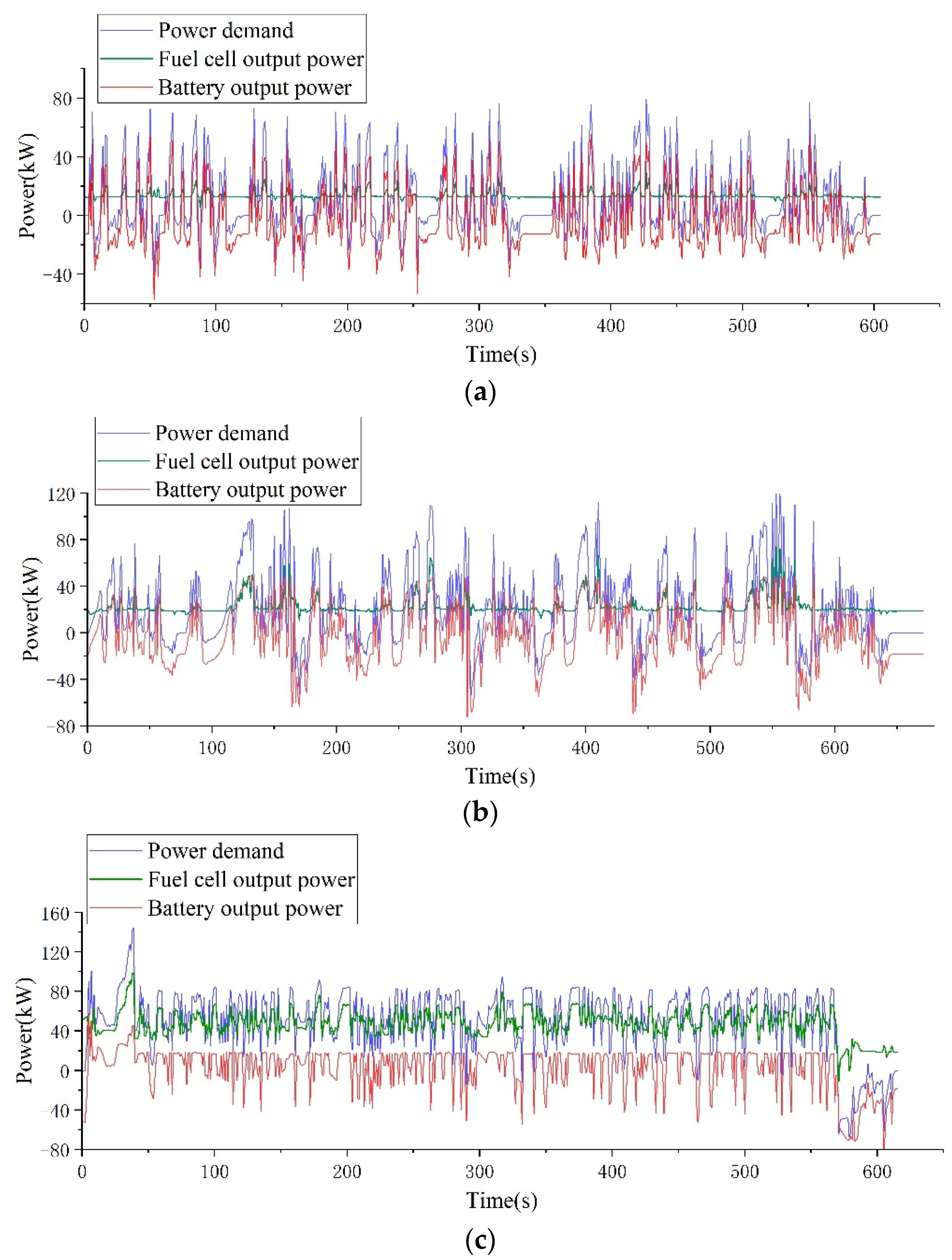
Real-time EMS based on control rule extraction under three different cycles is shown in Figure 14. As can be seen from Figure 14a, the output power of the fuel cell is relatively stable on the urban road with frequent start-stop and frequent acceleration and deceleration, and the large fluctuation of peak power and demand power is satisfied by the battery. Under suburban cycles in Figure 14b, the fuel cell still maintains a relatively stable output power, but there may be small fluctuations in areas with high power demand. From Figure 14c, it can be seen that under the highway cycle, the power demand remains at a relatively high level and fluctuates slightly. Although there are also many small fluctuations in the output power of fuel cells, the overall output power remains around 50 kW.
Based on the DP algorithm strategy, this paper compares the effect of three different energy management strategies:
  • The DP method is used to compute a global optimal solution based on known speed information for driving conditions. The offline solution obtained from DP serves as a benchmark;
  • The EMS proposed in this paper, based on control rule extraction, is designed for real-time application;
  • A rule-based state machine strategy considering fuel cell lifetime.

5.2.1. Analysis of SOC Performance

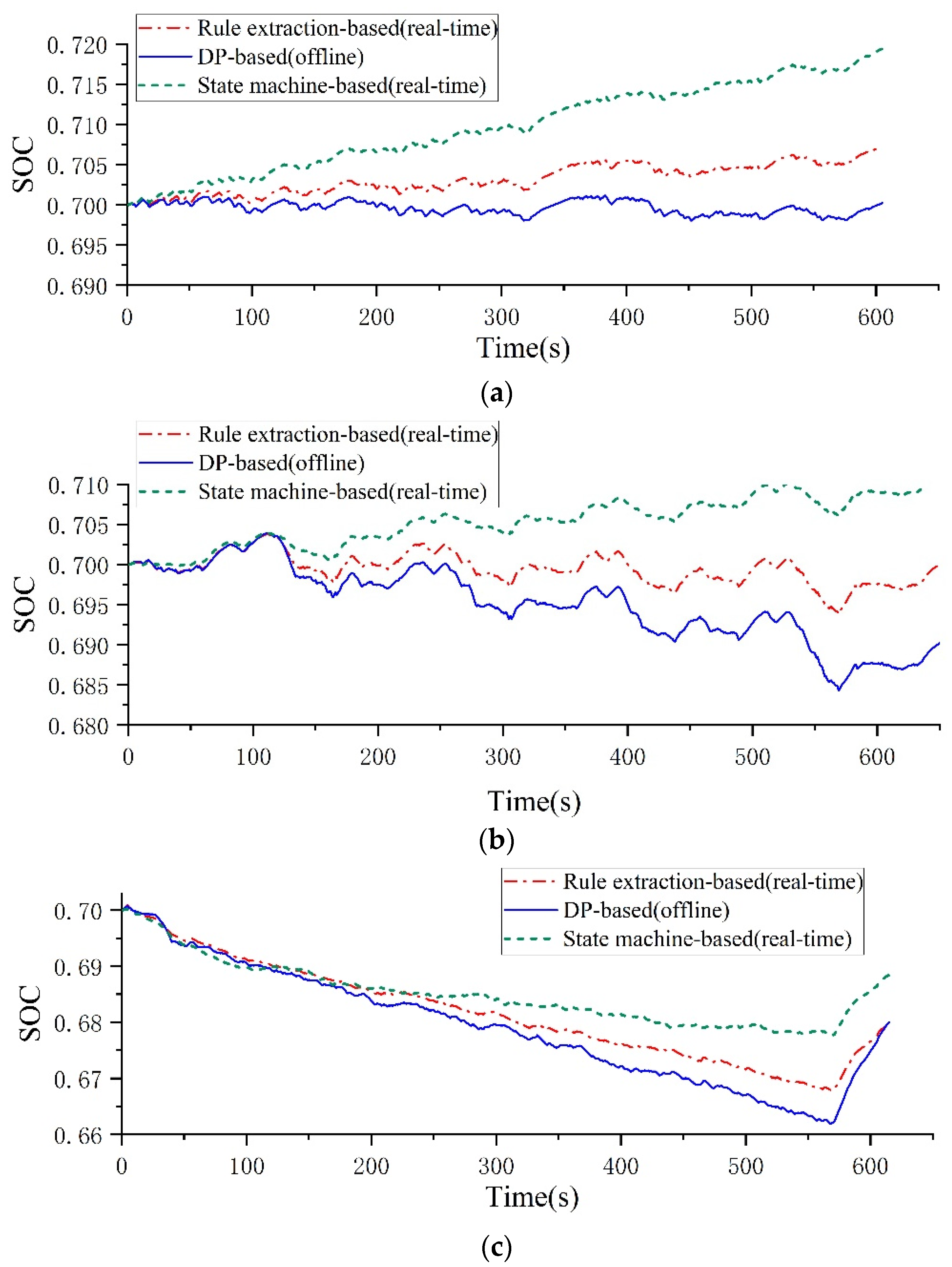
The SOC curves of battery with different energy management strategies under three driving cycles are shown in Figure 15. From Figure 15a,b, it is observable that during the urban and suburban cycles, the SOC curve of the state machine strategy shows an overall upward trend, and the final SOC value is much greater than that based on the DP strategy. Figure 15c shows the SOC curve under the highway cycle. Due to the high power demand under the highway cycle, the SOC curve predominantly exhibits a declining trend, but the final value SOC of the state machine strategy is still larger than that of the DP-based method. The rule extraction method extracts rules from the solution results of the DP algorithm. As a result, the overall SOC curve of this strategy closely resembles that of the DP-based method.

5.2.2. Analysis of Hydrogen Consumption and Fuel Cell Degradation

The total cost of different energy management strategies under urban, suburban, and highway cycles are listed in Table 5. It is evident that the total cost of the rule extraction strategy is lower than that of the traditional state machine strategy across all three driving cycles. Compared to the state machine-based strategy, the rule extraction-based strategy achieves reductions in the total cost ranging from 3.64% to 8.96%. At the same time, the total cost of the rule extraction strategy is very close to that of the DP strategy. For a better analysis of the cost per driving cycle, the data in Table 5 are divided into the cost of equivalent hydrogen and the cost of fuel cell degradation, as listed in Table 6. For the cost of equivalent hydrogen, the result of the rule extraction strategy is obviously better than that of the traditional state machine. For the cost of fuel cell degradation, because the state machine strategy used in this paper also considers the fuel cell lifetime, there is little difference between the three strategies. However, the cost of fuel cell degradation of the rule extraction strategy is lower than that of the state machine-based strategy.
For the analysis of hydrogen consumption, by observing the equivalent hydrogen consumption curve in Figure 16, it becomes evident that the traditional rule-based state machine strategy exhibits the highest hydrogen consumption across various cycles. On the other hand, the offline DP strategy can be considered a theoretically optimal solution, as it consistently demonstrates the lowest hydrogen consumption in different cycles. Meanwhile, the real-time control rule extraction strategy falls between the other two approaches. It outperforms the traditional rule-based strategy and comes close to the theoretically optimal solution.
To better assess the economy, the equivalent hydrogen consumption per 100 km is calculated and compared among the strategies based on rule extraction, state machine strategy, and DP strategy under different cycles. The results are shown in Table 7. The data show that the proposed strategy can save 14.5% to 18.04% hydrogen consumption compared with the state machine-based strategy, and the difference between the proposed strategy and the DP-based strategy is only 1.28% to 8.23%.
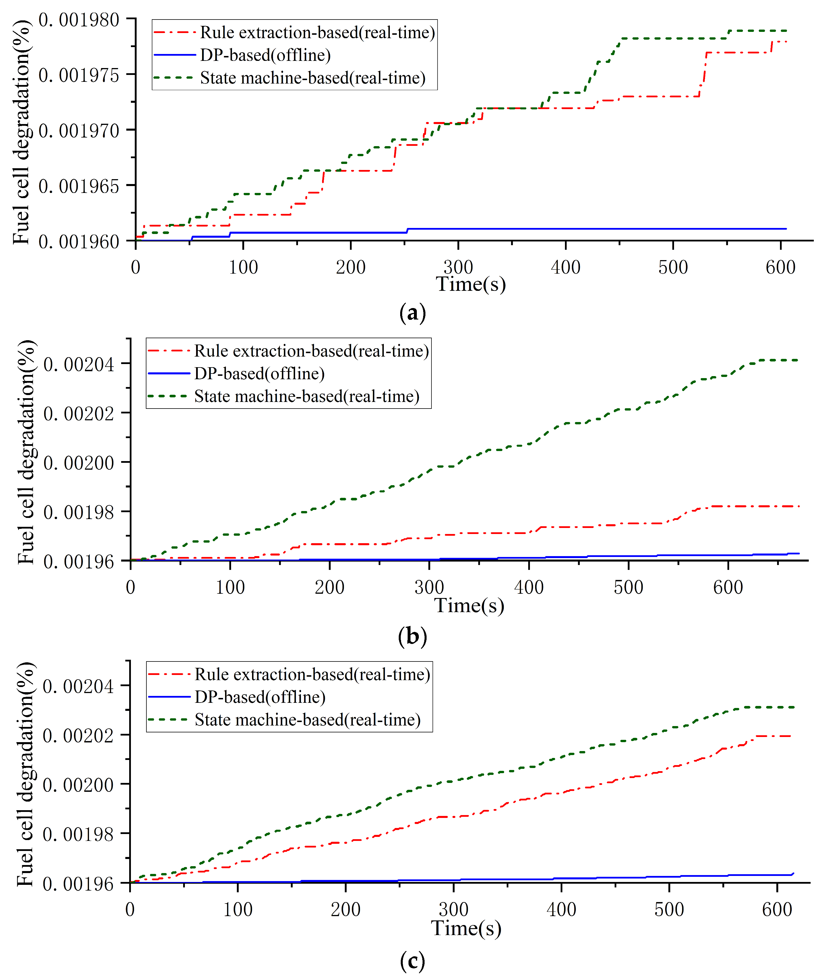
For the analysis of fuel cell degradation, it is clear from Figure 17 that the fuel cell degradation for the offline DP-based strategy is still optimal. In addition, the fuel cell degradation of the proposed strategy is less than that of the state machine-based strategy under various cycles. Therefore, the proposed EMS does not increase fuel cell degradation while reducing hydrogen consumption compared to conventional rule-based EMS. Note that the starting value of the vertical coordinate in Figure 16 is 0.00196%, which represents the degradation of a start-stop.
Based on the above analysis, the rule extraction strategy achieves real-time application. It maintains the fuel cell operating in its efficient power output range and effectively utilizes the role of the hybrid system’s battery. Compared to the state machine-based strategy, it reduces fuel cell power output fluctuations and hydrogen consumption and improves the economy of the vehicle and the life of the fuel cell.

6. Conclusions

In this paper, the optimal energy management problem for a fuel cell commercial vehicle is formulated using the DP algorithm, in which the hydrogen consumption and fuel cell life are taken as the cost function and the state variables are the SOC and the polarization voltage U p of the battery, while the control variable is the fuel cell output power. According to the results of DP, an EMS based on rule extraction is designed. Based on the results of DP off-line calculation, the rule base of the relationship between the input state variables and the fuel cell output power is obtained by the method of neural network training. According to the designed EMS, a driving simulation platform was built based on CARLA, SUMO, and MATLAB/Simulink, and the simulation was carried out under three simulation scenarios: urban cycle, suburban cycle, and highway cycle. The simulation results indicate that the performance of the proposed strategy closely approaches that of the DP strategy. Compared to the state machine strategy, the proposed strategy saves 3.64% to 8.96% in total cost and reduces hydrogen consumption by 14.5% to 18.04%, demonstrating its strong practicality and real-time control effectiveness.
Complex driving conditions and real traffic flow are a challenge for all optimization research of energy management strategies. Based on the proposed methodology, combined with the vehicle-road-cloud cooperative sensing and speed planning techniques, it should be possible to solve the robustness problem of energy management strategy under complex traffic flow conditions. This is also the next research direction of the paper.

Author Contributions

Conceptualization, Y.L.; formal analysis, Y.L., J.L., J.T. and J.Y.; investigation, Y.L., M.W., J.T. and J.L.; methodology, M.W.; writing—original draft preparation, M.W.; writing—review and editing, J.Y. All authors have read and agreed to the published version of the manuscript.

Funding

This research was funded by the Natural Science Foundation of Guangdong Province, grant number 2022A1515012080, and the Natural Science Foundation of Guangdong Province, grant number 2019A1515110562.

Data Availability Statement

The data that support the findings of this study are available from the corresponding author upon reasonable request.

Conflicts of Interest

Author Jiansheng Liang was employed by the company BYD Co., Ltd. The remaining authors declare that the research was conducted in the absence of any commercial or financial relationships that could be construed as a potential conflict of interest.

References

  1. Gao, Z.; Li, X.; Liu, Z.; Rao, J. Development trend and research status of the hydrogen fuel cell vehicle. Mater. Rep. 2022, 36, 74–81. [Google Scholar]
  2. Lü, X.; Qu, Y.; Wang, Y.; Qin, C.; Liu, G. A comprehensive review on hybrid power system for PEMFC-HEV: Issues and strategies. Energy Convers. Manag. 2018, 171, 1273–1291. [Google Scholar] [CrossRef]
  3. Teng, T.; Zhang, X.; Dong, H.; Xue, Q. A comprehensive review of energy management optimization strategies for fuel cell passenger vehicle. Int. J. Hydrogen Energy 2020, 45, 20293–20303. [Google Scholar] [CrossRef]
  4. Nie, Y.X.; Huang, D.Y.; Zheng, Z.Q. Research on energy management control strategy based on fuel cell electric vehicle. Mechatronics 2019, 6, 28–33. [Google Scholar] [CrossRef]
  5. Wang, Y.; Sun, Z.; Chen, Z. Energy management strategy for battery/supercapacitor/fuel cell hybrid source vehicles based on finite state machine. Appl. Energy 2019, 254, 13. [Google Scholar] [CrossRef]
  6. Song, K.; Chen, H.; Wen, P.; Zhang, T.; Zhang, B.; Zhang, T. A comprehensive evaluation framework to evaluate energy management strategies of fuel cell electric vehicles. Electrochim. Acta 2018, 292, 960–973. [Google Scholar] [CrossRef]
  7. Wang, Q.; Li, D.; Miao, H. Research on energy management strategy of fuel cell vehicle based on fuzzy logic control. Automot. Eng. 2019, 41, 1347–1355. [Google Scholar] [CrossRef]
  8. Sorlei, I.S.; Bizon, N.; Thounthong, P.; Varlam, M.; Carcadea, E.; Culcer, M.; Iliescu, M.; Raceanu, M. Fuel cell electric vehicles—A brief review of current topologies and energy management strategies. Energies 2021, 14, 252. [Google Scholar] [CrossRef]
  9. Li, H.; Ravey, A.; N’Diaye, A.; Djerdir, A. Online adaptive equivalent consumption minimization strategy for fuel cell hybrid electric vehicle considering power sources degradation. Energy Convers. Manag. 2019, 192, 133–149. [Google Scholar] [CrossRef]
  10. Zhou, W.; Yang, L.; Cai, Y.; Ying, T. Dynamic programming for new energy vehicles based on their work modes Part II: Fuel cell electric vehicles. J. Power Sources 2018, 407, 92–104. [Google Scholar] [CrossRef]
  11. Zhang, Q.; Li, G. A Game Theory Energy Management Strategy for a Fuel Cell/Battery Hybrid Energy Storage System. Math. Probl. Eng. 2019, 2019, 12. [Google Scholar] [CrossRef]
  12. Lü, X.; Wu, Y.; Lian, J.; Zhang, Y.; Chen, C.; Wang, P.; Meng, L. Energy management of hybrid electric vehicles: A review of energy optimization of fuel cell hybrid power system based on genetic algorithm. Energy Convers. Manag. 2020, 205, 112474. [Google Scholar] [CrossRef]
  13. Abdelqawee, I.M.; Emam, A.W.; ElBages, M.S.; Ebrahim, M.A. An improved energy management strategy for fuel cell/battery/supercapacitor system using a novel hybrid jellyfish/particle swarm/BAT optimizers. J. Energy Storage 2023, 57, 106276. [Google Scholar] [CrossRef]
  14. Geng, W.; Lou, D.; Wang, C.; Zhang, T. A cascaded energy management optimization method of multimode power-split hybrid electric vehicle. Energy 2020, 199, 117224. [Google Scholar] [CrossRef]
  15. Wei, X.; Liu, B.; Leng, J.; Zhou, X.; Sun, C.; Sun, F. Research on eco-driving of fuel cell vehicles via convex optimization. Automot. Eng. 2022, 44, 851–858. [Google Scholar] [CrossRef]
  16. Nguyen, C.T.; Nguyễn, B.H.; Trovão, J.P.F.; Ta, M.C. Optimal Energy Management Strategy based on Driving Pattern Recognition for a Dual-Motor Dual-Source Electric Vehicle. IEEE Trans. Veh. Technol. 2024, 73, 4554–4566. [Google Scholar] [CrossRef]
  17. Lu, D.; Yi, F.; Hu, D.; Li, J.; Yang, Q.; Wang, J. Online optimization of energy management strategy for FCV control parameters considering dual power source lifespan decay synergy. Appl. Energy 2023, 348, 121516. [Google Scholar] [CrossRef]
  18. Li, K.; Zhou, J.; Jia, C.; Yi, F.; Zhang, C. Energy sources durability energy management for fuel cell hybrid electric bus based on deep reinforcement learning considering future terrain information. Int. J. Hydrogen Energy 2024, 52, 821–833. [Google Scholar] [CrossRef]
  19. Song, K.; Wang, X.; Li, F.; Sorrentino, M.; Zheng, B. Pontryagin’s minimum principle-based real-time energy management strategy for fuel cell hybrid electric vehicle considering both fuel economy and power source durability. Energy 2020, 205, 118064. [Google Scholar] [CrossRef]
  20. Jeoung, H.; Lee, W.; Park, D.; Kim, N. Data-driven analysis of the correlation of future information and costates for PMP-based energy management strategy of hybrid electric vehicle. Int. J. Precis. Eng. Manuf.-Green Technol. 2022, 9, 873–883. [Google Scholar] [CrossRef]
  21. Wang, S.; Huang, X.; López, J.M.; Xu, X.; Dong, P. Fuzzy adaptive-equivalent consumption minimization strategy for a parallel hybrid electric vehicle. IEEE Access 2019, 7, 133290–133303. [Google Scholar] [CrossRef]
  22. Zeng, T.; Zhang, C.; Zhang, Y.; Deng, C.; Hao, D.; Zhu, Z.; Ran, H.; Cao, D. Optimization-oriented adaptive equivalent consumption minimization strategy based on short-term demand power prediction for fuel cell hybrid vehicle. Energy 2021, 227, 120305. [Google Scholar] [CrossRef]
  23. Jiang, Q.; Béthoux, O.; Ossart, F.; Berthelot, E.; Marchand, C. A comparison of real-time energy management strategies of FC/SC hybrid power source: Statistical analysis using random cycles. Int. J. Hydrogen Energy 2021, 46, 32192–32205. [Google Scholar] [CrossRef]
  24. Jia, C.; He, H.; Zhou, J.; Li, J.; Wei, Z.; Li, K. Learning-based model predictive energy management for fuel cell hybrid electric bus with health-aware control. Appl. Energy 2024, 355, 122228. [Google Scholar] [CrossRef]
  25. Shojayian, M.; Kjeang, E. Simulation of cathode catalyst durability under fuel cell vehicle operation–Effects of stack size and temperature. J. Power Sources 2024, 591, 233820. [Google Scholar] [CrossRef]
  26. Jiang, H.; Xu, L.; Li, J.; Hu, Z.; Ouyang, M. Energy management and component sizing for a fuel cell/battery/supercapacitor hybrid powertrain based on two-dimensional optimization algorithms. Energy 2019, 177, 386–396. [Google Scholar] [CrossRef]
  27. Fletcher, T.; Thring, R.; Watkinson, M. An Energy Management Strategy to concurrently optimise fuel consumption and PEM fuel cell lifetime in a hybrid vehicle. Int. J. Hydrogen Energy 2016, 41, 21503–21515. [Google Scholar] [CrossRef]
  28. Hu, Z.; Xu, L.; Li, J.; Ouyang, M.; Song, Z.; Huang, H. A reconstructed fuel cell life-prediction model for a fuel cell hybrid city bus. Energy Convers. Manag. 2018, 156, 723–732. [Google Scholar] [CrossRef]
  29. Hou, S.; Yin, H.; Xu, F.; Benjamín, P.; Gao, J.; Chen, H. Multihorizon predictive energy optimization and lifetime management for connected fuel cell electric vehicles. Energy 2023, 266, 126466. [Google Scholar] [CrossRef]
Figure 1. Fuel cell and battery hybrid power system topology structure.
Energies 17 03465 g001
Figure 2. Equivalent circuit of the Thevenin model.
Energies 17 03465 g002
Figure 3. Motor efficiency map.
Energies 17 03465 g003
Figure 4. CLTC-C driving cycle.
Energies 17 03465 g004
Figure 5. EMS based on DP results: (a) power distribution of power system; (b) SOC curve of battery; (c) the equivalent hydrogen consumption curve.
Energies 17 03465 g005
Figure 6. Scatter plot of the relationship between vehicle speed, requested torque, and fuel cell output power.
Energies 17 03465 g006
Figure 7. Fixed neural network structure.
Energies 17 03465 g007
Figure 8. Fuel cell output power rule library.
Energies 17 03465 g008
Figure 9. The control scheme of the proposed strategy.
Energies 17 03465 g009
Figure 10. Schematic diagram of the simulation platform.
Energies 17 03465 g010
Figure 11. Simulation under the urban cycle: (a) simulation scenario and driving route of the urban cycle; (b) speed curve of the urban cycle.
Energies 17 03465 g011
Figure 12. Simulation under suburban cycle: (a) simulation scenario and driving route of the suburban cycle; (b) speed curve of the suburban cycle.
Energies 17 03465 g012
Figure 13. Simulation under highway cycle: (a) simulation scenario and driving route of highway cycle; (b) speed curve of highway cycle.
Energies 17 03465 g013
Figure 14. Power distribution curves under different cycles: (a) urban cycle; (b) suburban cycle; (c) highway cycle.
Energies 17 03465 g014
Figure 15. SOC curves of different strategies under different cycles: (a) urban cycle; (b) suburban cycle; (c) highway cycle.
Energies 17 03465 g015
Figure 16. The equivalent hydrogen consumption curves of different strategies under different cycles: (a) urban cycle; (b) suburban cycle; (c) highway cycle.
Energies 17 03465 g016
Figure 17. The fuel cell degradation curves of different strategies under different cycles: (a) urban cycle; (b) suburban cycle; (c) highway cycle.
Energies 17 03465 g017
Table 1. Battery specifications.
ParametersValue
Nominal capacity (Ah)5.5
Nominal voltage (V)3.7
Charging termination voltage (V)4.2
Discharge cut-off voltage (V)3
Number of batteries in series145
Number of batteries in parallel15
Table 2. Degradation coefficients of the fuel cell.
CoefficientValueDefinitions
k 1 0.00126 (%/h)Output power below 10% of maximum power
k 2 0.00196 (%/cycle)One full start-stop
k 3 0.0000593 (%/h)The magnitude of load variation exceeds 10% of the maximum power
k 4 0.00147 (%/h)Output power exceeding 90% of maximum power
k p 1.47Used to correct the differences between the experimental and the simulation environment
Table 3. Fuel cell parameters.
ParametersValue
Maximum   power   of   fuel   cell   P f c _ m a x (kW)110
Rated   power   of   fuel   cell   P f c _ e (kW)90
The number of monomers in the stack.600
Table 4. Fuel cell commercial vehicle parameters.
ParametersValue
Unladen   mass   m ( k g ) 3450
Full   load   mass   m 1 ( k g ) 6400
Transmission   efficiency   η t 0.9
Windward   area   A ( m 2 ) 4.4
Rolling resistance coefficient f0.0086
Coefficient   of   rotational   mass   δ 1.2
Air   resistance   coefficient   C D 0.75
Wheel   radius   r ( m ) 0.367
Transmission   ratio   i 0 6.143
Table 5. Total cost under three driving cycles.
Driving CycleTotal Cost (USD)
Rule Extraction-BasedState Machine-BasedDP-Based
Urban2.06212.13712.0178
+3.64%−2.15%
Suburban2.51312.68612.4326
+6.88%−3.20%
Highway3.66233.99033.5983
+8.96%−1.75%
Table 6. Distribution of total cost.
Driving CycleStrategyTotal Cost
Equivalent Hydrogen Cost (USD)Fuel Cell Degradation (USD)
UrbanRule extraction-based0.40661.6555
State machine-based0.48081.6563
18.25%0.05%
DP-based0.37391.6439
−8.04%−0.70%
SuburbanRule extraction-based0.85411.659
State machine-based0.97761.7085
14.60%2.98%
DP-based0.7871.6456
−7.86%−0.81%
HighwayRule extraction-based1.97211.6902
State machine-based2.29041.6999
16.14%0.57%
DP-based1.94261.6557
−1.50%−2.04%
Table 7. Equivalent hydrogen consumption per 100 km under different cycles.
Driving CycleEquivalent Hydrogen Consumption per 100 km (kg)
Rule Extraction-BasedState Machine-BasedDP-Based
Urban3.163.732.90
+18.04%−8.23%
Suburban3.383.873.12
+14.50%−7.70%
Highway3.904.533.85
+16.15%−1.28%
Disclaimer/Publisher’s Note: The statements, opinions and data contained in all publications are solely those of the individual author(s) and contributor(s) and not of MDPI and/or the editor(s). MDPI and/or the editor(s) disclaim responsibility for any injury to people or property resulting from any ideas, methods, instructions or products referred to in the content.