Article

Time-Limited Aging Analysis of the Containment of Nuclear Power Plants without Monitoring Tendons

Nuclear and Radiation Safety Center, Ministry of Ecology and Environment, Beijing 100082, China
*
Author to whom correspondence should be addressed.
Energies 2024, 17(13), 3325; https://doi.org/10.3390/en17133325
Submission received: 4 May 2024 / Revised: 8 June 2024 / Accepted: 21 June 2024 / Published: 7 July 2024
(This article belongs to the Section B4: Nuclear Energy)

Abstract

:
A prestressed concrete containment is the enclosure structure of a nuclear reactor that serves as the last physical barrier of a nuclear power plant (NPP) safety defense system. It plays a key role in the prestress time-limited aging analysis (TLAA) required for operating license extensions for NPPs. Considering prestress containment systems without long-term monitoring tendons in a nuclear power plant, the technical route for prestress TLAAs involves analyzing operating license extension regulations and in-service monitoring technical requirements for prestressed tendons performance. Using tendons based on theoretical calculations of prestress loss in a nuclear power plant and the minimum required value of prestress determined by numerical simulation, the theoretical predictive value can be compared with the minimum required value for prestressed steel tendons. This comparison can be used to evaluate the 20-year life extension of the prestress system and provide a reference for aging and life management of NPPs.

1. Introduction

In recent decades, the focus of the nuclear power industry has shifted from constructing new nuclear power plants to extending the operational lifespans of existing ones. Extending the validity of nuclear power plant operating licenses has become a common international practice, and aging and life management have become significant international research topics [1,2,3,4,5,6]. The United States is a pioneer in the license renewal and life extension of nuclear power plants globally. As of early 2018, the U.S. Nuclear Regulatory Commission (NRC) had approved license renewal applications for 89 units [7]. China’s first nuclear power plant has a design life of 30 years and has been operating for nearly 30 years. The National Nuclear Safety Administration in China (NNSA) is conducting a review of operating license renewals, and more nuclear power plants will face license renewal challenges in the future. Regarding the life extension of NPPs, the NNSA document (NNSA (2015) No. 280) stipulates that the validity period for the renewal of a nuclear power plant operation license shall not exceed 20 years. The technical review required for the extension of a nuclear power plant’s operating license consists of two parts: an overall aging assessment and a time-limited aging analysis of specific components.
The containment is the enclosing structure of a nuclear reactor, and serves as the final physical barrier in a nuclear power plant’s safety defense system. Prestressed time-limited aging analysis is a crucial component of the overall time-limited aging analysis of a nuclear power plant. According to NUREG-1801 [8] issued by the NRC, prestressing time-limited aging analysis involves comparing the measured prestress value with the minimum required prestress value (MRV) at 1 year, the end of the design life, and the end of the life extension period to determine if life extension conditions are met. A nuclear power plant preparing for the review of its operating license renewal faces difficulties in conducting prestressed time-limited aging analysis due to the absence of long-term prestressed monitoring steel bundles, which prevents the monitoring of the actual force values during the service period. This paper compares the theoretical predictive value of prestressed steel strands with the MRV during the license renewal period and evaluates the conditions a prestressed system must meet for a 20-year life extension.

2. License Renewal Regulations and In-Service Monitoring Requirements for Prestressed Steel Tendons

2.1. Regulatory Standards for NPP License Renewal

The United States is a leading country in the utilization of nuclear energy and nuclear technology. The NRC has developed and issued a comprehensive system of regulatory guidance and technical documents for the supervision of license renewal, and has accumulated substantial practical experience. The highest-level regulatory document in the United States for renewing nuclear power plant operating licenses is the Atomic Energy Act, followed by federal regulations. The third level includes the NRC’s regulatory guides (RGs) and NUREG documents, with NUREG-1800 [4] and NUREG-1801 [9] being the most critical. The fourth tier consists of the NRC’s day-to-day regulatory documents. U.S. nuclear power industry standards and technical documents from industry associations are fundamental for aging management and license renewal of nuclear power plants. France has 58 PWR nuclear power plants in operation, most of which will reach the 40-year operating license period between 2019 and 2032, and will generally face the challenge of extending the validity of their operating licenses.
Since the beginning of 2017, the NNSA has conducted nuclear safety reviews and supervision for the renewal of nuclear power plant operating licenses, primarily based on the “Nuclear Safety Law of the People’s Republic of China” and the NNSA (2015) No. 280 document, while also referring to NUREG-1800, NUREG-1801, and other documents.

2.2. Monitoring Requirements for Time-Limited Aging Analysis of Prestressed Systems

Title 10 of the Code of Federal Regulations, Part 54.3, requires a time-limited aging analysis as a crucial component of an application for an operating license extension. Title 10 CFR Part 54.21 specifies requirements for time-limited aging analysis, and evaluation results must comply with criteria outlined in 10 CFR Part 54.29. NUREG-1800 and NUREG-1801 clarify methods and acceptance criteria for time-limited aging analysis of prestressed concrete containment, focusing on grouting steel bundles. Requirements for grouting steel bundles are discussed on a case-by-case basis. According to US RG1.90 [10], the monitoring scheme for grouting steel beam performance should include monitoring the containment prestress level by instrumentation and pressure testing (scheme A) and monitoring the deformation of the containment under pressure testing (scheme B). For all schemes, regular pressure tests of the containment are required.
Representative vertical steel bundles in the containment structure of a nuclear power plant are filled and compacted with cement mortar after the initial structural integrity test, making all the steel bundles grouted, which prevents monitoring the actual force of the prestressed steel bundles during the in-service period. This presents a challenge in the time-limited aging analysis of the prestressed system. According to the final safety analysis report of a nuclear power plant, the in-service inspection of grouted steel bundles is verified using RG1.90 scheme B. Additionally, the visual inspection of specified structural key parts and anchor components is conducted in accordance with the requirements of C.4 in RG1.90. Structural acceptance testing adheres to requirements of CC-6000 of the ASME Code, Volume III and Volume II (ACI359) [7,9].
Based on the above analysis, the life prediction of a prestressed system can be achieved through the prediction of prestress loss, and a technical route for time-limited aging analysis is proposed. Prestress loss is a key factor affecting the service performance of containment structures. The primary purpose of time-limited aging analysis is to evaluate the influence of prestress loss on containment structures over time.

3. Design and Loss Calculation of Prestressing System of a Nuclear Power Plant

3.1. Project Overview

A nuclear power plant with a design life of 30 years has been operating for nearly 27 years. The containment structure is a prestressed concrete structure with a sealed steel lining, which consists of a foundation floor, a cylinder, a ring beam, a dome, etc. The inner diameter of the containment is 36.0 m, the inner height of the containment is 64.1 m, the wall thickness of the containment cylinder is 1.0 m, the center of the equipment gate hole is +21.385 m, and the opening diameter is 3.5 m. The dome is 1.0 m thick. A section of the containment structure is shown in Figure 1. The concrete strength grade is C40 and the thermal expansion coefficient is 1 × 10⁻⁵/°C. The design basis internal pressure is 0.23 MPa (abs) [11].
The prestressing system consists of dome steel bundles, cylinder circumferential steel bundles, and vertical steel bundles. The containment structure adopts the post-tensioning method steel strand prestressing system. The wall of the cylinder is provided with 460 hoop stress steel bundles and 336 vertical steel bundles, which are arranged in two layers: the inner and outer layers. The dome has 213 beams, which are arranged in three layers. The prestressed steel bundle is considered as an ideal elastic material, Poisson’s ratio μ = 0.3, and the thermal expansion coefficient is 1 × 10⁻⁵/°C.

3.2. Internal Force Analysis of Containment under Internal Pressure

The PWR containment is a single-layer prestressed reinforced concrete structure, comprising a dome, a cylinder, and a foundation slab. The cylinder is typically a cylindrical structure, and the dome can be either a flat shell type or a hemispheric type. The entire containment is an axisymmetric structure with a relatively thin thickness compared to the radius of the containment. Its design adheres to the film stress theory, and its internal forces can be calculated using the no-moment theory. For the containment barrel section:
σ m = P D 4 S σ θ = P D 2 S
For containment domes:
σ m = σ θ = P D 4 S

3.3. Theoretical Calculation of Prestress Loss

When an operating organization applies for a 20-year extension of the operating license of a nuclear power plant, it is necessary to estimate the prestress during the extended life operation. The prestressing system adopts 1770 grade high-strength and low-relaxation steel bundles with a diameter of 15.7 mm, a nominal area of 150 mm2, and a control stress (σcon) = 1325 MPa. The elastic modulus of the steel strand is 1.95 × 10⁵ MPa. The calculation process of the effective prestress is as follows: according to relevant construction data, predict the prestress of the containment at the end of the continuous operation period; compare the actual prestress loss trend with the original design, and confirm that the prestress loss trend conforms to assumptions of the original design; after data are obtained, the trend is carried out. This analysis is intended to demonstrate that the prestressing is sufficient for the extended operating period.
For the post-tensioned prestressed system, the primary causes of prestress loss include (1) friction between the prestressed steel bundle and the tunnel wall; (2) deformation of the prestressed steel bundle anchorage, retraction of the steel bar, and compression of the joint; (3) elastic compression of the concrete; (4) stress relaxation of the prestressed strands; and (5) shrinkage and creep of the concrete. Calculated combinations of these loss values are listed in Table 2 [12]. Anchor deformation and friction loss between tunnel walls are determined based on the results of an on-site 1:1 model test [11].
Based on the combination of prestress loss in Table 2 and the calculation formula in the literature [10], this paper calculates the prestress loss at the end of the license renewal period (i.e., after 50 years of nuclear power plant operation) and determines the effective prestress in the standard area of the containment structure. Theoretical calculation values are listed in the results.

4. Numerical Model of Prestress and Determination of Minimum Required Value

4.1. Structural Model of Prestressed System

In this paper, the prestressed concrete containment structure is accurately modeled. When establishing the model, first distinguish the prestressed steel tendons, and establish the concrete model (SOLID element) and the prestressed steel tendon model (LINK element), as shown in Figure 2. The prestressed steel strands and the surrounding concrete deformation are coordinated [13].
Prestressed steel bundles have different effective prestresses along their tensile length. Via programming (APDL language), different temperature loads are applied to different element nodes of each prestressed steel bundle to achieve accurate application of effective prestressing. After the model is built, the strain, stress, and deformation values of the containment structure under the action of the test peak pressure are first calculated, and then calculated values are compared with the pressure test values to verify the accuracy of the calculation model.

4.2. Response of Containment Structure under Peak Internal Pressure

Radial deformation of the containment and concrete strain parameters are the important contents of the structural integrity test, and the judgment of test results is also an important basis for acceptance criteria. To verify the accuracy of the finite element model, the structural response of the containment structure under the peak pressure of the pressure test was calculated and compared with the peak pressure in the most recent in-service inspection (the third in-service inspection in 2018) during the pressure test. The measured values of the lower barrel strain were compared.
(1)
Radial deformation
Radial deformation is an important parameter reflecting the safety of the containment structure, which can form a macroscopic understanding of the containment structure during the crushing test. In this paper, the radial deformation is calculated, and the thickening and strengthening of the surrounding area of the gate opening is not considered in the calculation.
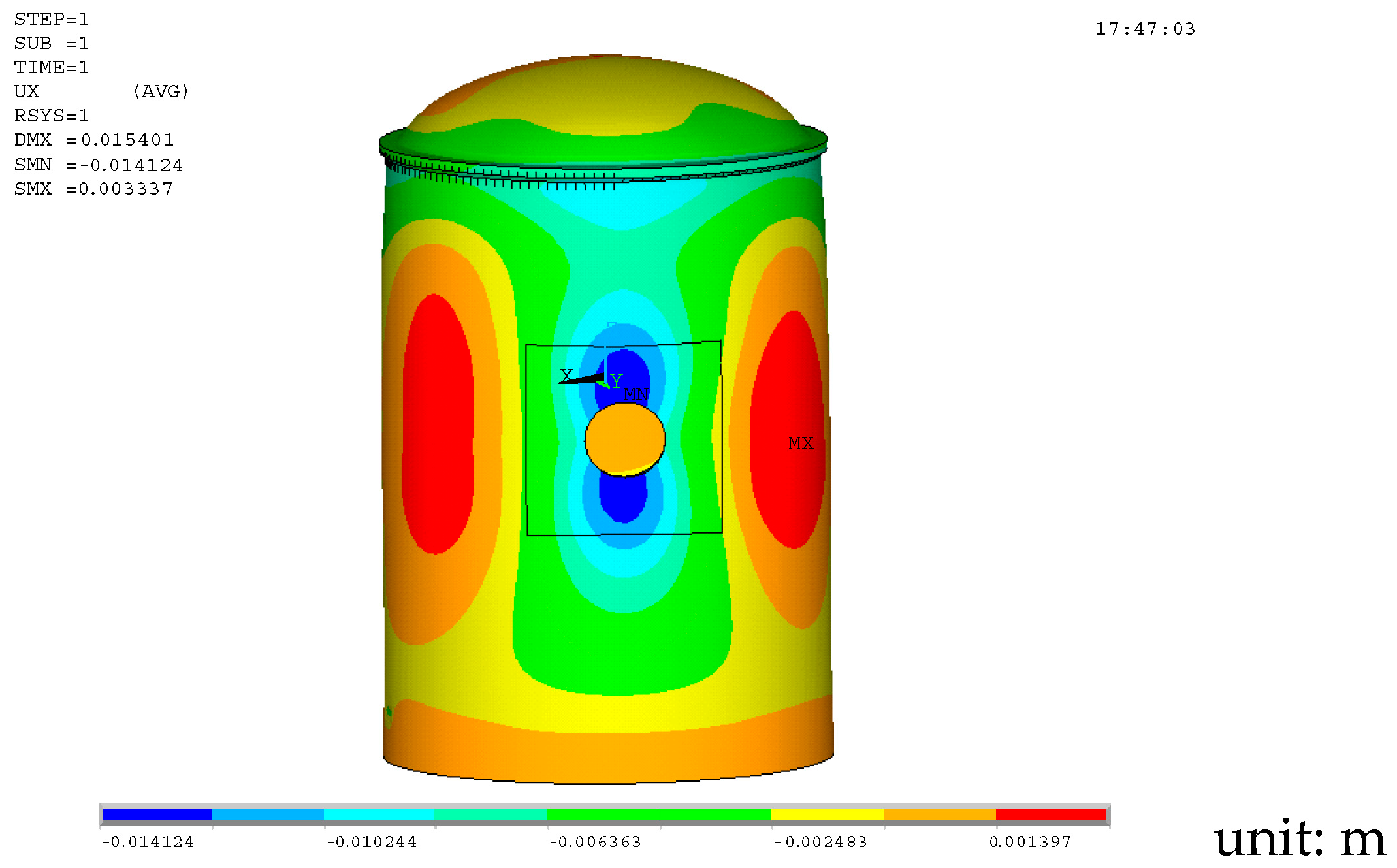
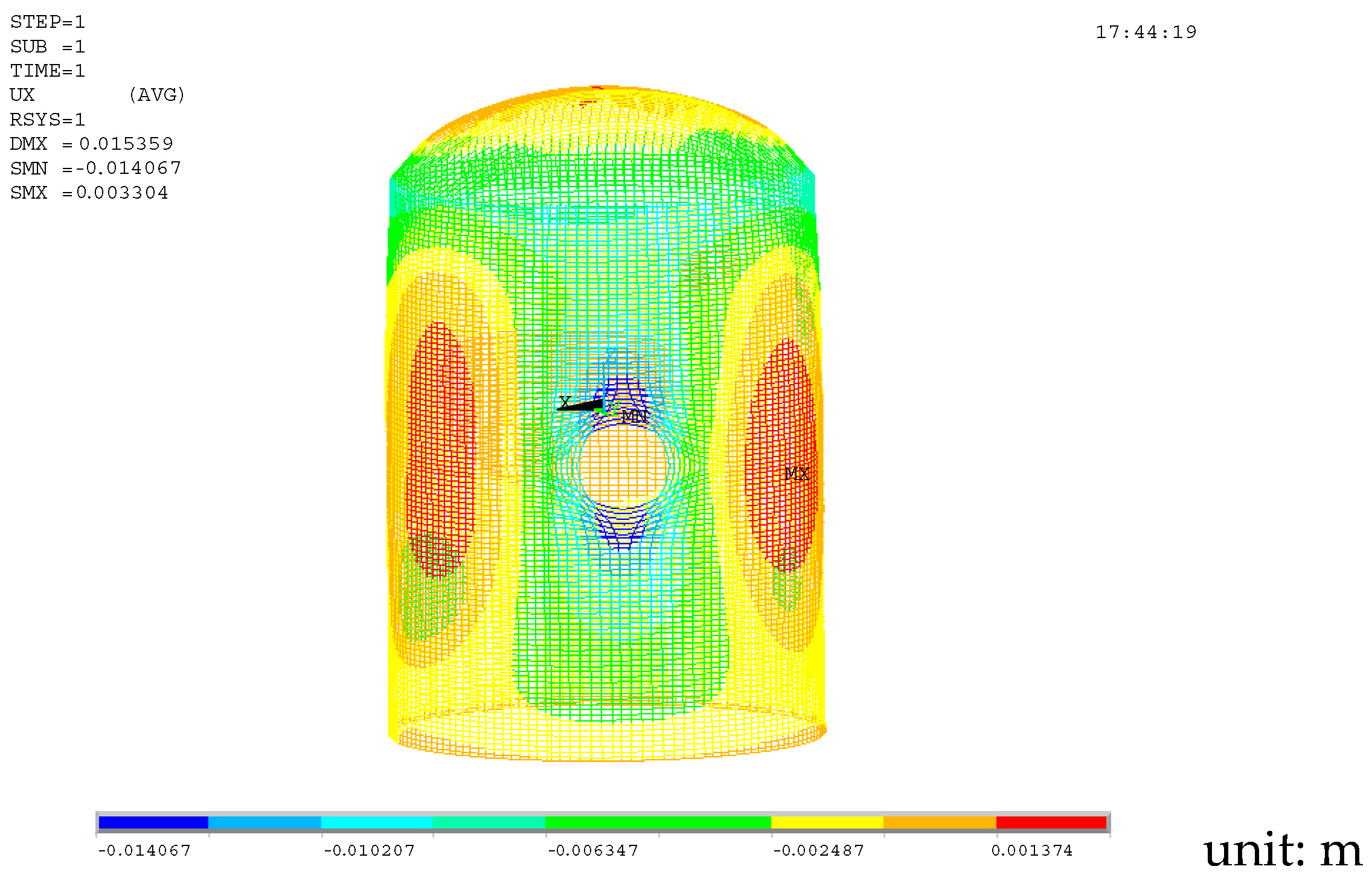
The radial displacement of the containment under peak pressure is shown in Figure 3. The radial displacement of the prestressed steel bundle under the action of internal pressure is shown in Figure 4.
It can be seen from Figure 3 and Figure 4 that the overall structure of the containment undergoes outward expansion deformation under the action of the peak pressure. The calculation shows that the radial displacement of the containment wall is larger than that of the dome; especially, the radial deformation of the equipment gate opening is the largest. Other parts of the containment wall and the dome also underwent outward expansion deformation to varying degrees. The inward displacement of the upper and lower parts of the gate opening reached 14.12 mm, while the outward displacement of the left and right parts of the opening was less than 10 mm. The dome and other parts of the containment vessel wall have also undergone outward expansion deformation to varying degrees, but the displacement is relatively small, generally around 2-3 mm. The numerical calculation of a maximum radial displacement of 2-3 mm in this paper is close to the theoretical calculation result of the containment of 2 mm, indicating that the numerical calculation results are credible and can be used as the basis for the horizontal radial deformation.
(2)
Strain analysis
The decisive factor for concrete cracking is whether the tensile strain of concrete under compressive load reaches the limit value [14]. The strain of concrete in the containment structure is the most direct parameter that reflects the working state of the containment structure.
The radial deformation calculation shows that the gate opening of the equipment is subjected to complex forces and the deformation is large.
It can be seen that under the action of the peak pressure of 0.23 MPa, the cylinder wall around the gate opening has tensile strain in some areas, the maximum strain is 145 × 10−6, and the concrete cracking strain is 114 × 10−6, so there are concrete cracks in some areas. Cracks are possible, but far from reaching the state of rebar-yielding structural failure. Most of the hoop and vertical strains of the containment structure are negative, and the overall structure is in a state of compression.
Therefore, under the conditions of the integrity test, the prestressed steel bundles bear most of the peak pressure, the concrete containment is still in a state of compression as a whole, basically in an elastic state, which meets the requirements of the relevant specifications, and the structure has sufficient safety margin. The above conclusions are consistent with those of the nuclear power plant containment integrity test, which verifies the correctness of the numerical simulation.
Under peak pressure, the calculated stress and strain values at the cylinder’s measuring points are in good agreement with the experimentally measured values, proving the accuracy of the calculation model. This model can be used for calculating the minimum required prestress value.
(3)
Overall test verification
The nuclear power plant containment structure completed the first structural integrity test (SIT) in 1990, and the test pressure was 1.15 times the design basis pressure (design basis pressure: 0.26 MPa); the first in-service inspection of the containment structure was completed in 2000 (1ISI test, 10a). The 3ISI test started on 25 June 2018 and ended on 1 July 2018, which lasted 6 days and nights, and the highest test pressure was 0.230 MPa (Figure 5). Check whether the maximum strain and deflection values of the containment conform to the theoretical predictions and compare with data from the first integrity in-service inspection (1ISI test) to determine whether the safety margin specified by the containment design is reduced due to operating and environmental conditions. Next, determine whether existing cracks on the surface of the containment continue to expand and whether new destructive cracks are generated during the pressure test.
Under the maximum test pressure, the displacement value at the expected maximum radial deformation (DF-08) is 2.072 mm, which is 49% of the expected displacement (4.237 mm); the displacement value at the expected maximum vertical deformation (DF-17) is 3.52 mm, which is 125% of the expected displacement (2.808 mm). The measured displacement values did not exceed 130% of the expected value, meeting the acceptance criteria. At the same time, the displacement value at the measured maximum radial deformation (DF-04) is 2.813 mm, which is 92% of the expected displacement (3.054 mm); the actual measurement is the same as the expected maximum vertical displacement. Therefore, at the maximum test pressure, the measured displacement values did not exceed 130% of the predicted values at the measured maximum radial and vertical displacements. To sum up, the containment structure is still in an elastic working state during the compression process, the overall performance is good, and it meets the acceptance criteria.

4.3. Calculation of Minimum Required Value of Prestress

The main purpose of prestress time-limited aging analysis is to evaluate the effect of the loss of prestress over time on the containment structure, which is generally evaluated using the minimum required value (MRV) of the prestress. MRV refers to the minimum effective prestress required to ensure that the design function of the structure is intact at the end of its use after the loss of prestress over time. MRV is an important parameter when evaluating whether the prestressed system meets the design requirements after the prestress loss of the containment structure. It is required that the critical control section of the containment structure should not have tensile stress during the entire life cycle [15].
According to the original design drawings, a finite element simulation calculation model of the prestressed containment was established. Based on the principle that the most unfavorable section of the containment concrete should not experience tensile stress under the designed internal pressure, the MRV calculation was performed. Measured data from the containment strength test were then used to verify the accuracy of the model. In the analysis of the containment structure model, the MRV of the tensile end of the steel bundle, calculated by comparing structural responses under different prestress losses, peak pressure, and gravity, was determined to be 870.5 MPa. Comparing the vertical (1098.75 MPa), hoop (906.74 MPa), and dome (997.9 MPa) steel beam prestress prediction values of the containment with the MRV demonstrates that the effective prestress of the containment at the end of the 50-year operation of the nuclear power plant exceeds the proposed MRV. Therefore, the prestressing system will maintain its normal function during the extended operation of the nuclear power plant, meeting the conditions for life extension.

5. Conclusions and Recommendations

Considering the fact that a nuclear power plant does not have long-term prestressed monitoring steel strands, the technical route for the aging analysis of containment prestressed time limit is proposed as analyzing license continuation regulations and technical requirements for in-service monitoring of the performance of prestressed steel strands. Numerical simulations and previous containment structural strength tests have shown that, except for concrete surface cracks in some areas, most of the containment is in an elastic state, which meets the requirements of relevant codes, and the overall structure of the containment has sufficient safety margin. Comparing the predicted value of vertical, circumferential, and dome steel beam prestresses with MRVs proved that the effective prestress is greater than the MRV at the end of the 50-year operation of the nuclear power plant, so the prestressing system of the nuclear power plant has the conditions required for 20-year life extension.
During the license renewal period, a prestressing system should be regularly inspected and maintained in strict accordance with the requirements of the containment aging management program. For key areas, such as gate openings, it is recommended to address defects promptly based on the results of regular tests and monitoring to ensure the effective function of the containment.

Author Contributions

Conceptualization, F.S. and G.R.; methodology, F.S.; software, F.S. and G.R.; validation, G.R.; formal analysis, F.S. and G.R.; investigation, F.S.; resources, G.R.; data curation, G.R.; writing—original draft preparation, F.S.; writing—review and editing, F.S. and G.R.; visualization, G.R., F.S. and G.R.; project administration, F.S.; funding acquisition, F.S. All authors have read and agreed to the published version of the manuscript.

Funding

This research received no external funding.

Data Availability Statement

The original contributions presented in the study are included in the article, further inquiries can be directed to the corresponding author.

Conflicts of Interest

The authors declare no conflict of interest.

References

  1. Yi, P.; Wang, Q.K.; Kong, X.J. Aseismic safty analysis of a prestressed concrete containment vessel for CPR1000 nuclear power plant. Earthq. Eng. Eng. Vib. 2017, 16, 55–67. [Google Scholar] [CrossRef]
  2. Chakraborty, M.K.; Acharya, S.; Pisharady, A.S. Assessment of ultimate load capacity of concrete containment structures against structural collapse. Nucl. Eng. Des. 2017, 323, 417–426. [Google Scholar] [CrossRef]
  3. Liang, Y.P.; Feng, D.C.; Ren, X.D. High-fdelity numerical analysis of the damage and failure mechanisms of a prestressed concrete containment vessel under internal pressure. Nucl. Eng. Des. 2021, 383, 111439. [Google Scholar] [CrossRef]
  4. Wang, J.; Yang, L. Method discussion of concrete containment buildings longevity assessment in NPP. Ind. Constr. 2015, 45, 182–191. (In Chinese) [Google Scholar]
  5. Feng, P.; Chai, G.; Li, L. Preliminary Study on Response Law of Prestressed Concrete Containment Vessel after LOCA in Certain NPP. At. Energy Sci. Technol. 2015, 49, 1815–1820. (In Chinese) [Google Scholar]
  6. Yang, L.; Wang, Y.; Lin, S. Assessment and management of aging concrete containment buildings for nuclear power plants. Ind. Constr. 2009, 39, 1094–1098. (In Chinese) [Google Scholar]
  7. NUREG-1800; Standard Review Plan for Revise of License Renewal Applications for Nuclear Power Plants. Nuclear Regulatory Commission: Rockville, MD, USA, 2010.
  8. ASME. Boiler and Pressure Vessel Code: Section III: Devision 2: Code for Concrete Containment; ASME: New York, NY, USA, 2004. [Google Scholar]
  9. NUREG-1801; Generic Aging Lessons Learned (GALL) Report. Nuclear Regulatory Commission: Rockville, MD, USA, 2010.
  10. Nuclear Regulatory Commission. Regulatory Guide 1.90 Inservice Inspection of Prestressed Concrete Containment Structures with Grouted Tendons, Revision 2; Nuclear Regulatory Commission: Rockville, MD, USA, 2012.
  11. NB/T20017-2010; Containment Structural Integrity Test of Pressurized Water Reactor Nuclear Power Plant. National Energy Board: Beijing, China, 2010.
  12. Sun, F.; Pan, R.; Wang, L.; Mao, H.; Yang, Y. Study on effective prestressing effects on concrete containment under the design-basis pressure condition. Nucl. Saf. 2013, 12, 20–25. (In Chinese) [Google Scholar]
  13. Sun, F.; Y, T.; Fu, Q. Discussion on Duration of Maximal Pressure Plateau in Containment Structure Integrity Test. At. Energy Sci. Technol. 2016, 50, 1846–1852. (In Chinese) [Google Scholar]
  14. GB 50010-2010; Specification for Design of Concrete Structures. China Construction Industry Press: Beijing, China, 2011.
  15. NB/T20303-2014; Specification for Design of Prestressed Concrete Containment of Pressurized Water Reactor Nuclear Power Plant. National Energy Board: Beijing, China, 2014.
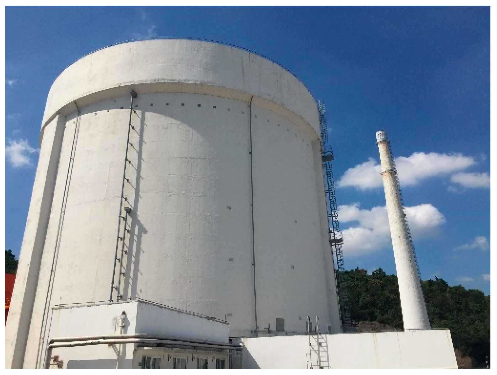
Figure 1. Containment structure on-site photos.
Energies 17 03325 g001
Figure 2. ANSYS model of containment vessel structure (a) and prestress tendon in dome (b).
Energies 17 03325 g002
Figure 3. Radial displacement of concrete containment under internal pressure.
Energies 17 03325 g003
Figure 4. Radial displacement of prestress tendon under internal pressure.
Energies 17 03325 g004
Figure 5. Actual buck–boost curve in test.
Energies 17 03325 g005
Disclaimer/Publisher’s Note: The statements, opinions and data contained in all publications are solely those of the individual author(s) and contributor(s) and not of MDPI and/or the editor(s). MDPI and/or the editor(s) disclaim responsibility for any injury to people or property resulting from any ideas, methods, instructions or products referred to in the content.