Abstract
With the increase in the amount of actual operating data on electric vehicles, how to analyze and process useful information from existing battery charging and discharging data and apply it to subsequent state estimation is worthy of in-depth thinking and practice by researchers. This article proposes a collaborative estimation architecture for SOC and SOH based on the 1RC equivalent circuit model, recursive least squares, and adaptive extended Kalman filtering algorithms (AEKF), which combine offline data processing with online applications. By applying offline data processing, OCV–SOC polynomial fitting and average polarization resistance were determined, which reduced the time required for basic data measurement and improved the accuracy of model parameter identification, while a recursive estimation combining micro- and macro-time-scales of AEKF was used for the online real-time estimation of the SOC and actual available capacity of batteries, in order to eliminate interference from measurement and process noise. The results of the simulated and experimental data validation indicate that the proposed algorithm is applicable to the lithium-ion batteries studied in this paper, the average SOC deviation is less than 1.5%, the maximum deviation is less than 2.02%, and the SOH estimation deviation is less than 1% under different driving conditions in the multi-temperature range. This study lays the foundation for further utilizing offline data and improving SOC and SOH collaborative estimation algorithms.
1. Introduction
As an important automotive energy storage component [1,2], the accurate estimation of the state of charge (SOC) and state of health (SOH) of lithium-ion batteries is related to the reliability and safety of automotive operation [3]. The SOC can monitor the battery’s charge to avoid over-charging and over-discharging, and to avoid irreversible changes in the positive active substance structure and abnormal battery capacity attenuation. In SOC estimation, it is crucial to prevent abnormal battery capacity degradation, as temperature fluctuations in the battery may compromise the reliability of SOC estimation, potentially leading to thermal runaway risks [4]. SOH can monitor the aging state of the battery to determine the maintenance and replacement time of the battery which can improve the safety of the battery [5]. In this study, SOC is defined as the ratio of the current available capacity to the current actual capacity, and SOH is defined as the ratio of the current actual capacity to the initial capacity. SOC and SOH are defined as follows:
where Cn_aca indicates the capacity stored by the battery in its current state; Cn_act indicates the maximum capacity that the battery can store in its current state; Cn_ini indicates the maximum capacity that can be stored when the battery is still new.
It can be seen from Formulas (1) and (2) that the calculation of SOC and SOH both use Cn_act, indicating both correlation and difference, but both need to identify Cn_act, and the calculation of SOC requires the use of Cn_act; if SOH is known, based on the capacity of the new battery, Cn_act can be obtained. If the relationship between the two is ignored and only a single SOC or SOH estimate is made, then this will lead to a reduction in the accuracy of the estimation results [6,7]. Therefore, joint estimation of SOC and SOH will provide a good solution to the problem of battery state estimation. At present, there have been a lot of studies on SOC and SOH estimation, and the research directions for SOC estimation mainly focus on the table lookup method, ampere-hour integration method, data-driven method, and filter method. The table lookup method is a simple and fast method for SOC estimation based on the relationship between OCV and SOC [8], but it requires the battery to stand for a long time and is not suitable for online applications. The ampere-hour integration method uses Coulomb counting to estimate the SOC [9]. This method is simple and efficient, but due to the existence of initial values and cumulative errors, it will cause large estimation errors. The data-driven method [10,11,12,13] has high precision, but it needs a lot of training data, while the calculation is complex and the calculation efficiency is low, so it is not suitable for online application. Considering that as the battery SOH declines, the battery parameters will also change accordingly, Guo F et al. [14] proposed a multi-time-scale SOC and parameter estimation method based on double extended Kalman filters (EKFs) and adjusted the parameters of the double extended Kalman filters in joint estimation by means of empirical tuning. The EKF algorithm requires substantial computational efforts for adjusting error covariances, which limits its engineering application value. In order to address the limitations related to model description bias in traditional EKF algorithms, researchers have conducted extensive research; representative examples include Shuzhi Z et al. [15], who proposed a joint capacity and SOC estimation framework based on the adaptive extended Kalman filter (AEKF). The model parameters are obtained online via the RLS method with the forgetting factor, and then the SOC and capacity are estimated jointly by two AEKF estimators. The joint estimation algorithm can better deal with the coupling relationship between SOC and SOH estimation, improve the accuracy of two-state estimation, and result in good application prospects. However, in the process of algorithm application, the accuracy of model parameter identification was not analyzed, and a large number of experiments are still needed to obtain basic data such as those on OCV–SOC.
If the model parameters required for recursive calculation are inaccurate or the regression convergence speed is slow, fluctuations and inaccuracies in SOC state estimation will occur. Therefore, in practical engineering applications, offline measurement results obtained through hybrid power pulse test (HPPC) identification under laboratory conditions are often used [16]. Although stable model parameter identification results have been obtained, as the SOH decreases, the stored offline identification results may no longer be applicable. Thus, during the entire life cycle of the battery, the identification of model parameters also needs to be performed using online identification methods [17,18]. Dai H et al. [19] proposed a multi-time-scale extended Kalman filter, which considered the fast–slow variation characteristics of battery parameters, and carried out parameter identification on different time scales, with reliable parameter identification results and high precision. Inspired by this study, a joint estimation algorithm that can be applied online was developed to improve the state monitoring capability of a battery management system in this article. In order to obtain basic data such as those on OCV–SOC relationships, accurately identify model parameters that adapt to the fast and slow characteristics of batteries, and meet the requirements for the joint estimation of SOC and SOH, this paper establishes a multi-time-scale AEKF algorithm that combines offline parameter identification and online parameter identification for the joint estimation of SOC and SOH.
The application of joint estimation algorithms in engineering practice requires the acquisition of basic data, accurate identification of model parameters, and reasonable development of joint state estimation algorithms. The above content requires a collaborative approach to overcome the current research shortcomings such as the time-consuming measurement of OCV–SOC relationships, low accuracy of model parameter identification leading to algorithm non-convergence, and lack of updating mechanisms for dual-state joint estimation algorithms. The main contributions of this article are as follows: (1) For offline working condition data, the FFRLS algorithm was applied to identify the required basic data, including the OCV–SOC correspondence and polarization resistance R1 value. While ensuring the accuracy of the identification results, a large amount of testing time was saved. (2) During the implementation of model parameter identification and state estimation algorithms, the accuracies of multiple algorithms were gradually verified and compared with each other to obtain more accurate and practical algorithm collaboration solutions. (3) Through stepwise verification and comparative analysis of the accuracy of multiple methods, an effective and practical implementation plan for a high-precision joint state estimation algorithm was determined. The rest of this paper is as follows: In the second section, an improved SOC and SOH collaborative estimation scheme is proposed, which considers the adaptive identification of fast and slow battery characteristic model parameters, as well as the fast acquisition method of SOC–OCV basic data. In the third section, a feasibility verification method from the sub-part of the model to the whole model is proposed based on the battery simulation data. In the fourth section, the reliability of the algorithm is verified using the measured data. Finally, the main contributions are summarized in the fifth section.
In order to ensure the accuracy of SOC and SOH estimation, it is necessary to establish a more suitable battery model, which requires the identification of appropriate model parameters and can reflect the fast and slow changing characteristics of the battery. At present, there are extensive studies on battery models, and a variety of different battery models have been proposed in various of these, including the electrochemical model [20,21], fractional equivalent circuit model [22,23], and equivalent circuit model [24,25]. Among them, the electrochemical model and fractional equivalent circuit model are complicated; their calculation efficiency is low and the online application of them is difficult. The first-order RC model is the best among the integer-order equivalent circuit models due to its high accuracy, low complexity, and ease of computation, making it the preferred choice for the joint estimation algorithm in this paper. As shown in Figure 1, the first-order RC ECM simulates the terminal voltage through a resistance unit and the polarization process through an RC network, and its state space equation is shown in the following equation:
where UOCV represents the open-circuit voltage of the battery corresponding to the SOC. Ut stands for terminal voltage; U1 stands for polarization voltage; R0 is the ohmic internal resistance; R1 and C1 are polarization parameters, representing polarization resistance and polarization capacitance, respectively. I indicates the load current, which acts as an excitation on the battery model and is positive when charging and negative when discharging.
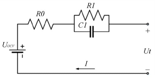
Figure 1.
First-order RC equivalent circuit model.
SOC is calculated via the ampere-hour integration method, which is as follows:
where SOC(0) represents the initial SOC value; Cn indicates the battery capacity.
2. The Improved Collaborative SOC and SOH Joint Estimation Scheme
In this paper, improved collaborative SOC and SOH joint estimation is realized through a multi-time-scale double adaptive extended Kalman filter (DAEKF), aiming to fully utilize the actual operational data already stored in the cloud and achieve the accurate joint estimation of SOC and SOH; the implementation process of the scheme is shown in Figure 2. The algorithm architecture consists of three parts: the recurrent least square method with the forgetting factor (FFRLS), micro-time-scale AEKF, and macro-time-scale AEKF. The functions of each algorithm module are as follows: (1) The FFRLS algorithm module needs to be run twice for offline data processing and online real-time operation. FFRLS for offline data processing, utilizing the terminal voltage data stored in the cloud under variable current excitation, calculates and analyzes OCV and R1, and the online data processing FFRLS runs on BMS to process real-time voltage–current data and obtains R0 in real time to adapt to the fast-changing characteristic of the battery. (2) The micro-time-scale AEKF, using the battery SOC as the variable to be identified and terminal voltage as the observation, is used for the regression recursive calculation of the first-order RC equivalent circuit model of the battery. (3) The macro-time-scale AEKF uses the actual available capacity of the battery, which is Cn, as shown in Formulas (1) and (2), and the polarization capacitance, which is C1, as shown in Formula (3), with slow changing characteristics, as the variables to be identified for regression recursive calculation. The specific data processing process and calculation steps are shown in the following figure.
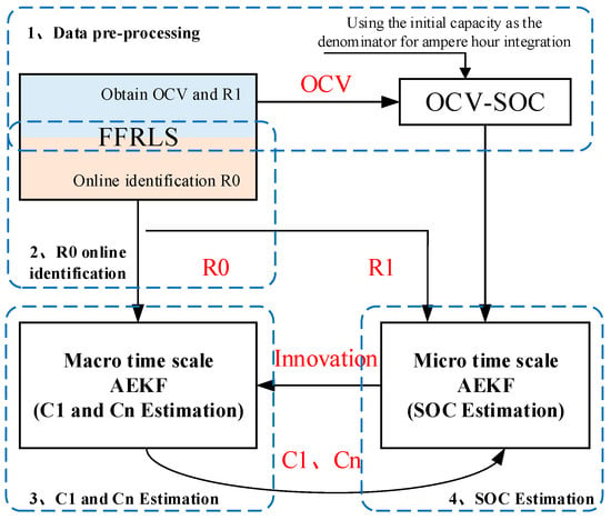
Figure 2.
Joint SOC and SOH estimation scheme.
2.1. Offline Data Pre-Processing
The purpose of offline data pre-processing is to obtain a more accurate OCV–SOC correspondence with minimal testing costs, to reduce the difficulty of parameter identification in the later stage, and to improve the convergence speed of capacity identification results by solidifying R1. Combined with the battery model shown in Figure 1, this part intends to obtain recognition results for OCV and R1 related to the sampling time through the offline FFRLS algorithm. FFRLS for offline operation performs parameter identification through the current and terminal voltage values at adjacent moments, so it is necessary to conduct Laplace transform on the battery state space equation to obtain the transfer function, as shown in the following equation:
The s operator is converted into a z operator via the backward difference method, and the transfer function after discretization is shown in the following equation:
where y is the difference between the terminal voltage and the open-circuit voltage, which is represented by y = Ut − Uocv; ΔT indicates the sampling interval.
We can obtain the difference equation via the inverse transformation of z, and by expanding y in the difference equation to Ut − Uocv; at last, we can obtain the following difference equation via transmutation:
The coefficients in front of each term in the difference equation are defined by the following equation:
The Uocv analytical formula can be derived from the coefficients α1 and α4, and the R1 analytical formula can be derived from α1, α2, and α3, as shown below:
At this point, the analytical expression of the difference equation and parameters for FFRLS calculation is obtained. Further, OCV and R1 are calculated through the iterative process of FFRLS. The equation of the FFRLS algorithm is as follows:
where Φk is the data variable, θk is the parameter variable, and ε is the model error, which follows the Gaussian distribution of the zero mean.
The calculation process of offline FFRLS includes five steps: parameter initialization, input determination, coefficient matrix, gain and error covariance calculation, online parameter identification, and recurrence.
- (1)
- Parameter initialization: θ0, P0;
- (2)
- Determine the input and parameter vectors:
- (3)
- Gain and error covariance calculation:
- (4)
- Parameter identification:
- (5)
- Recursion process:
k = k + 1. Enter the next round of calculation.
At the end of the recurrence process, the coefficient matrix of the difference equation can be obtained, and the specific values of OCV and R1 can be obtained recursively by analyzing Formula (9). In the calculation of gain and error covariance, FFRLS introduces the forgetting factor, λ, which is usually a constant less than 1, representing the weight of the past data relative to the current data, with a value of 0.998.
Taking the initial capacity as a denominator, the SOC curve calculated using Formula (4) is fitted with the identified OCV curve via RLS to obtain the OCV–SOC relationship. In the process of application, the corresponding relationship is represented as a two-dimensional table for reference. It can also be fitted with polynomials and used to find partial derivatives in EKF recursive calculation.
The polarization parameters of the battery belong to the slow changing stage and should not vary significantly with the excitation current rate. In the actual application process, when the temperature is constant, R1 should be fixed. Therefore, for the data already stored in the cloud, the average value of R1 at the low current of each segment is taken as the fixed value, and the calculation process is shown in the following equation:
where n is the data segment number, which can be segmented based on whether there is a zero current.
2.2. R0 Online Identification
According to Formulas (5)–(8), R0 can also be processed by the FFRLS algorithm. However, since R0 belongs to the parameter of the battery fast change stage parameter of the battery, different battery temperatures, SOC, and SOH can all affect its value, so it is required that the processing algorithm runs online. The analytical formula can be derived from coefficients α1 and α3 in Formula (8), and the calculation formula is as follows:
The derivation process of FFRLS for recursive solutions of R running online is the same as that of FFRLS running offline introduced in Section 2.1, while the forgetting factor value is also the same; both of these are 0.998.
2.3. AEKF SOC Estimation Algorithm for Micro-Time-Scale Operation
For date collected offline, since the measurement noise of voltage and current sensors and the process noise generated by modeling are unknown, it is necessary to introduce the AEKF algorithm that can adapt to the observation noise and process noise, and achieve SOC estimation at the micro-time-scale level. The implementation of the AEKF algorithm first requires writing the state space equation, and then linearizing the state transition matrix and observation matrix. The state space equation for SOC estimation is as follows:
where matrix xk is the state variable of the system at moment k, uk is the control input variable of the system at moment k, matrix A is the state transition matrix, matrix B is the control input matrix of the system, yk is the output matrix of the system at moment k, which is the observed signal value of the system, C is the observation matrix, and D is the feedforward matrix. ωk and υk represent the process noise and observed noise input to the system, respectively.
Based on the selected 1RC ECM and the state space equation listed in Formula (13), this paper selects the polarization voltage, U1, and SOC as the state variables together, as shown below:
In Formula (13), the state equation related to Xk is linear, but due to the presence of OCV–SOC nonlinear terms in the observation equation of yk, the linearization of the observation equation of yk is necessary to enable the AEKF algorithm to perform recursive calculations. The coefficients of the linearized state equation and observation equation are as follows:
where τ represents the time constant, τ = R1C1.
In addition to the derivation and linearization of the above equations, the DAEKF algorithm also needs to determine the calculation time sequence. This article stipulates that in the macro-time-scale calculation of step m, the micro-time-scale estimation of step L needs to be run. After the micro-time-scale accumulation operation of step L, the macro-time-scale calculation step is updated from m to m + 1, and the micro-time scale starts from 1 again for subsequent accumulation operation. According to this definition, the micro-time-scale calculation process is as follows:
- (1)
- Initialize the micro-time-scale SOC estimator: set the initial SOC estimator values:
Start the micro-time-scale, and calculate step k = 1:L.
- (2)
- Micro-time-scale SOC estimator time update:
A prior estimate of the state quantities is used to calculate a set of state quantities through the equivalent circuit model, as shown in Equation (16).
State error covariance is calculated using the state transition matrix and process noise, and the calculation formula is shown in Equation (17):
The prior estimate of the terminal voltage can be calculated according to the prior estimate of the state quantity, as shown in Equation (18):
- (3)
- The calculation of innovation: Define innovation as the difference between the measured terminal voltage value and the prior estimated terminal voltage value, as shown in Formula (19):
- (4)
- Micro-time-scale SOC estimator measurement update:
Kalman gain is determined according to the prior estimate of the state error covariance and the observed Jacobi matrix, which is an important coefficient for SOC estimation. The calculation formula is as follows:
The updates to state variables and error covariance are shown in the following equation:
where I′ is the identity matrix.
- (5)
- Adaptive update Qx and Rx
The process noise and observation noise represent the error in the model calculation process and the error in the acquisition of observation values, respectively. In the actual application process, the error is in a time-varying state. The adaptive algorithm can update Qx and Rx through the innovation data from the previous time to ensure the real-time and accuracy of the noise.
The opening window length of the adaptive algorithm is defined as M_mic, and the root mean square of the innovation is calculated, as shown in Equation (22):
Then, the process noise and observation noise calculated by the adaptive algorithm are as follows:
- (6)
- Time scale update
When the micro-time-scale is k = L, the micro- and macro-time-scale steps will be updated.
So far, the micro-time-scale SOC estimation scheme has been elaborated.
2.4. Macro-Time-Scale C1 and Cn Estimation
In the macro-time-scale AEKF algorithm, this paper selects C1 in the polarization stage and the battery capacity, Cn, that needs to be calculated as the state variables, and it also selects the terminal voltage as the observation value. The reason for selecting C1 as the state variable in the polarization stage is that R1 was fixed in the offline data processing stage shown in Section 2.1. Although the value of R1 is very close to the true value, there are still some errors. Therefore, it is necessary to recursively calculate it based on the slowly changing state variable, C1, to compensate for the errors in R1 and improve the accuracy of polarization voltage estimation.
For the multi-time-scale DAEKF joint estimation algorithm in this article, the micro-time-scale requires the SOC as the estimation result output to the macro-time-scale AEKF. If there is a large update to SOC state variables during the callback period of the micro-time-scale SOC estimator, it may cause fluctuations or even the non-convergence of the macro-time-scale AEKF algorithm in capacity estimation results. Therefore, this article makes the following provisions on the timing of macro-time-scale opening: during the macro-time-scale period of the first 200 steps, only micro-time-recursive calculations and SOC updates are run, and when the length of calculation is 200 steps, the joint estimation algorithm for micro- and macro-time-scales AEKF will start running. The calculation process of the macro-time-scale estimator is as follows:
Firstly, the macro-time-scale AEKF also requires the establishment of a state space equation, as shown in Formula (25):
where the observation matrix, , is consistent with Equation (13), which is the terminal voltage calculation formula.
Then, the recursive iteration process of the Kalman filter is started, and the algorithm flow is as follows:
- (1)
- Initialize the macro-time-scale parameter estimator. Set the initial value of the parameter estimator, . is the initial value of the parameter, is the initial value of the covariance of the parameter error, is the initial value of the process noise of the parameter estimator, and is the initial value of the observation noise of the parameter estimator.
Macro-time-scale parameter estimation starts, calculating step m = 1:∞.
- (2)
- Macro-time-scale parameter estimator time update. Perform the calculation of parameters and parameter error covariance prior estimates:
- (3)
- Macro-time-scale parameter estimator measurement update. Update the parameter estimator Kalman gain.
The equation of state and observations in Equation (13) can be expressed as the following functions:
The derivation process of Equation (27), , is made up of a group of iterative equations, as shown in Equation (29):
The state update of the parameter estimator is calculated via the last step of the micro-time-scale under each macro-time-scale, and the error covariance is updated, as shown in the following equation:
- (4)
- Adaptive update of .
The macro-time-scale adaptive algorithm is similar to the micro-time-scale, and its calculation process is as follows:
The opening window length of the adaptive algorithm is defined as M_mac, and the root mean square of the innovation is calculated, as shown in Equation (31):
Then, the process noise and observation noise are updated:
Formulas (25)~(32) represent the AEKF iteration process for the macro-time scales of C1 and Cn. Starting from the 200-step macro-time scale, each macro-time scale calculation will generate an update of the C1 and Cn results. In order to further reduce the fluctuation of the Cn calculation results, this research used the method of averaging the most recent 40% capacity estimation results shown in Formula (33) to calculate the average of the actual available capacity of the battery. Further, the battery SOH was calculated using Equation (2).
where N is the total length of the capacity calculation results on a macro-time scale.
The actual available capacity displayed by the same battery at different temperatures may vary, but the SOH results obtained by the same battery at different temperatures should be the same. After using Formula (33) to estimate the actual available capacity of the battery, for the calculation of SOH at different temperatures, it is necessary to establish the corresponding relationship between battery capacity and temperature as shown in the following equation:
where T is the battery temperature, and the unit is °C; , are dimensionless constants.
So far, the offline data processing and online real-time calculation of battery OCV–SOC correspondence, ECM parameter identification, and the joint estimation algorithm of SOC and SOH based on DAEKF algorithm and its iterative process have been introduced.
3. Algorithm Feasibility Verification Based on Simulation Data
Before establishing the simulation data, it should be noted that the simulation data used in the verification methods of all simulation data schemes in this paper are the same data set, which was constructed according to the off-line parameter identification results of ternary lithium-ion batteries with a capacity of 120 Ah.
3.1. Feasibility Verification of Constructed OCV–SOC Relationship
The measured current value is taken as input, and a set of DST conditions is taken as input in this paper. Given a set of known OCV–SOC relationships and fixed parameters in the first-order RC equivalent circuit model, a set of terminal voltages, that is, ideal terminal voltages, can be obtained through simulation. The obtained terminal voltage and current are used as input to verify the identification results of OCV and R1 in the preliminary data processing scheme. In order to ensure the rationality of the simulation data, the given OCV–SOC relationship curve and parameter values refer to off-line parameter identification results. The given OCV–SOC correspondence is shown in Figure 3. Given the internal resistance of ohm is 0.00065 Ω, the internal resistance of polarization is 0.000 2Ω, the polarization capacitance is 50,000 F, the battery capacity is 120 Ah, and the initial SOC is 1; the voltage constructed is shown in Figure 4.
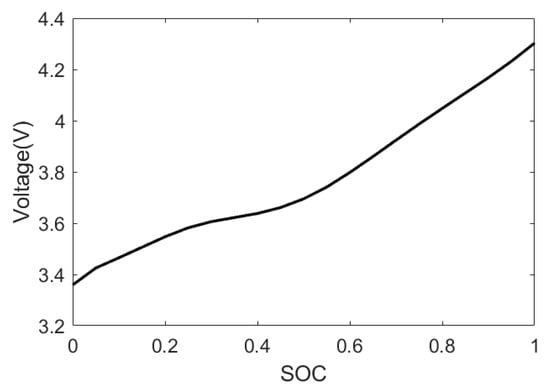
Figure 3.
OCV–SOC relationship curve.
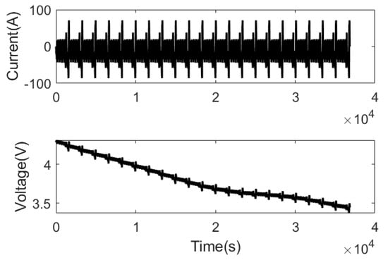
Figure 4.
Current–voltage curve.
With the current and voltage in Figure 4 as inputs, OCV and R1 are identified through FFRLS, the identification results of OCV are compared with the given OCV, and the R1 value is compared with the given R1 value, as shown in Figure 5 and Figure 6.
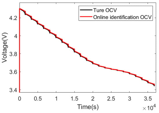
Figure 5.
OCV curve comparison.
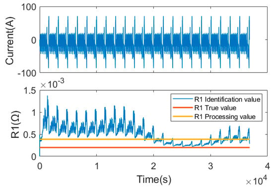
Figure 6.
R1 identification result.
As can be seen from Figure 6, the identification result of R1 is greatly affected by the current. When the current increases rapidly, the identification result of R1 deviates greatly from the real value. Therefore, the online application of the R1 value identified via FFRLS to the joint calculation of SOC and SOH will result in the deterioration or even non-convergence of the error estimation result. R1 calculated using Equation (11) is 0.00038 Ω, which greatly reduces the error compared with that when R1 is identified online, as shown in Figure 6. As can be seen from Figure 5, the OCV identified via FFRLS is very close to the real OCV. Further, the identified OCV and the SOC obtained ampere hours integration with a capacity of 120 Ah are fitted via least squares, and the constructed OCV–SOC correspondence is compared with the given OCV–SOC correspondence, as shown in Figure 7. It can be seen that in the SOC range of 0.1–1, the identified and constructed OCV–SOC corresponding relationship almost coincides with the given OCV–SOC corresponding relationship. The reason for the large error in the OCV–SOC corresponding relationship in the range of 0–0.1 in SOC is that the current data used in establishing the ideal voltage curve are the measured data. When the set capacity is 120 Ah, the SOC is 0.08 when discharge ends, and there is no identification result of OCV in the SOC range of 0–0.08. Therefore, the fitted OCV–SOC correspondence has a large error in this SOC range. In summary, from the level of the simulation data, the designed scheme of constructing the initial OCV and obtaining the fixed value of R1 is feasible, and the reliability and stability of the scheme need further verification using the measured data.
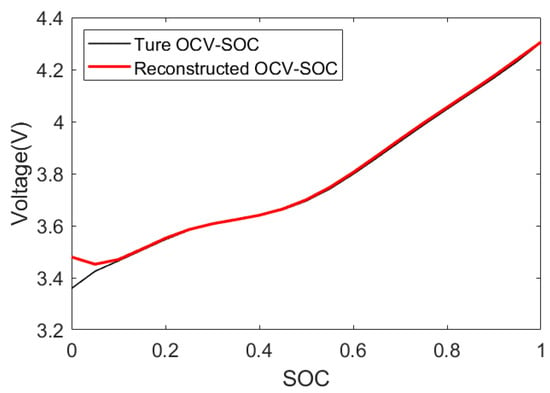
Figure 7.
Comparison of two OCV–SOC curves.
With reference to the method described in reference [14], the OCV–SOC is fitted in the form of a polynomial, as shown in Equation (35). The coefficients in the formula were obtained by fitting the OCV and SOC data with the least squares method.
3.2. Feasibility Verification of FFRLS Online Identification of R0 and C1
We use the same current and voltage as those in Section 3.1 to verify the simulation test data and compare the identification results with the given R0 value, output a set of C1 identification results at the same time, and analyze the feasibility of C1 identification through the results. The identification results of R0 are shown in Figure 8, and the identification results of C1 are shown in Figure 9. As can be seen from Figure 8, the identification result of R0 is very close to 0.00065, and the identification result is slightly different at 20,000 to 30,000 micro steps, but the error is still within 2%, indicating that the R0 result of FFRLS online identification is reliable and can be applied online to the joint calculation of the SOC and SOH estimate. The identification result of C1 is similar to that of R1, and the result is poor at a high current. If the same processing method is used as that use for R1, the whole polarization voltage will have a large deviation. As a result, the prior estimates of terminal voltage will have a large deviation, which will affect the accuracy and stability of the SOC and SOH estimation results. Therefore, C1 is estimated through the macro-time scale and capacity simultaneously.
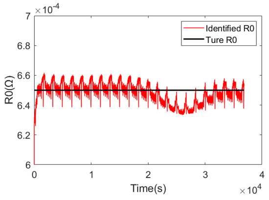
Figure 8.
R0 identification result.
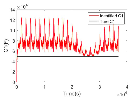
Figure 9.
C1 identification result.
3.3. Feasibility Verification of Micro-Time-Scale SOC Estimation
The simulation test data with the same current and voltage as those in Section 3.1 were used to verify the accuracy of SOC estimation, and the initial SOC value was set to 0.8 to verify the robustness of SOC estimation in the case of an initial deviation. In the calculation process, battery parameters R0 and R1 were identified using the methods in the previous two sections, and C1 parameters were set to the same as those in Section 2.1, so the SOC estimation results and errors were obtained, as shown in Figure 10. It can be seen that for the simulation data, the SOC can be accurately estimated when the battery parameters are clear, and the error can be maintained below 1%. In addition, when there is an error in the initial SOC, the SOC can be quickly corrected and return to the real SOC within 100 micro-time-scale steps, which proves the reliability of the SOC estimation.
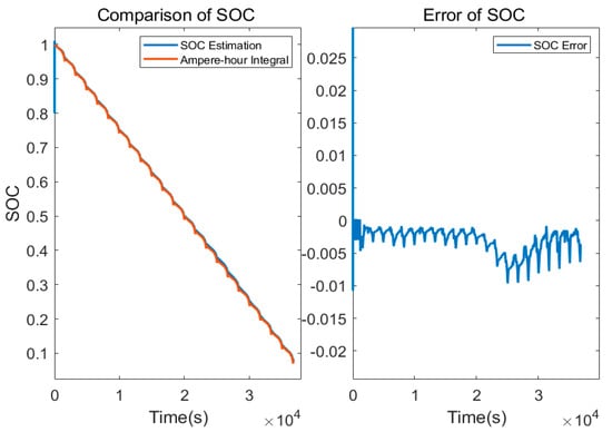
Figure 10.
Estimated results and errors of SOC.
3.4. Feasibility Verification of Macro-Time-Scale C1 and Capacity Estimation
The accuracy of C1 and capacity estimates was verified using simulation data on the same current and voltage as those in Section 3.1. The macro-time scale in the scheme is designed as 100 micro-time-scale steps. Given accurate R0 and R1 values, C1 and capacity are verified only through the joint estimation algorithm, and the results are shown in Figure 11. It can be seen that the estimated result of C1 is adjusted back from the initial value of 75,000 F to around 50,000 F, which is close to the true value, and the estimated result of capacity is adjusted back from the initial 90 Ah to 119.1 Ah, with an error of less than 1%, which proves that the C1 and capacity estimation scheme is feasible. The macro-time-scale step was further changed to 10 and 200 micro-time-scale steps, and the results are shown in Figure 12 and Figure 13, respectively. As can be seen from the results of Figure 12 and Figure 13, when the macro-time scale is too small, the results of C1 and capacity estimation fluctuate greatly, and C1 deviates from the true value more. When the macro-time-scale is too large, the capacity callback speed is slow, and C1 deviates from the true value more. Therefore, the selection of the macro-time scale should be between the mentioned two. When the macro-time scale is 100, the estimation results of capacity and C1 meet the accuracy requirements.
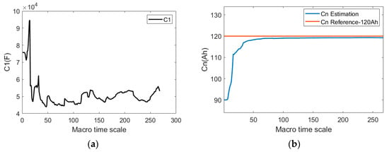
Figure 11.
Estimated results when the macro-time-scale length is 100 (accurate R0 and R1 values): (a) Estimated result of C1; (b) estimated result of capacity.
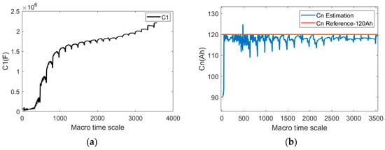
Figure 12.
Estimated results when the macro-time-scale length is 10: (a) estimated result of C1; (b) estimated result of capacity.
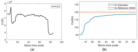
Figure 13.
Estimated results when the macro-time-scale length is 200: (a) estimated result of C1; (b) estimated result of capacity.
When the macro-time-scale steps are further changed to 10 and 200 micro-time-scale steps, as shown in Figure 12 and Figure 13, it can be seen that if the macro-time-scale is too small, the results of C1 and capacity estimation fluctuate greatly, and C1 deviates from the true value. Furthermore, if the macro-time scale is too large, the capacity callback speed is slow, and C1 deviates from the true value more. Therefore, the selection of the macro-time scale should be between the two. When the macro-time scale is 100, the estimation results of capacity and C1 meet the accuracy requirements.
4. Algorithm Feasibility Verification Based on Measured Data
The same type of battery was used to verify the measured data scheme; the capacity was 115 Ah, the test driving condition was NEDC, and the temperature was 25 °C. The actual data were verified in accordance with the previous data processing scheme, R0 online identification scheme, precision improvement effect of joint estimation scheme, and SOC and SOH joint estimation scheme.
4.1. Verification of Previous Data Processing
The actual capacity of the battery is 115 Ah under the NEDC condition at 25 °C. The identification results are shown in Figure 14. It can be seen from the identification results that OCV can track the measured terminal voltage more accurately, and the trend is consistent with the measured terminal voltage. The identification result of R1 fluctuates, and the result ranges from 0.0001 Ω to 0.001 Ω, which conforms to the resistance value range of a 115 Ah capacity. R1 is 0.00017 Ω, as calculated by Equation (11). In summary, it is considered that the measured data are applicable to this scheme and the estimated results are reliable.
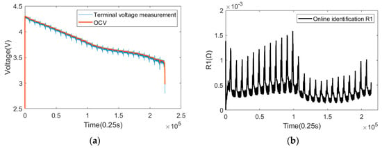
Figure 14.
Previous data processing results: (a) identification result graph of OCV; (b) identification result graph of R1.
4.2. R0 Online Identification Scheme Verification
The identification results are shown in Figure 15. It can be seen from the identification results that the identification results of R0 are relatively stable, ranging from 0.0006 Ω to 0.0008 Ω, in line with the resistance value range of a 115 Ah capacity, and the resistance value becomes larger in the lower SOC region, in line with the basic trend that the resistance value changes with the SOC. It is considered that this scheme is reliable when applied to the measured data.
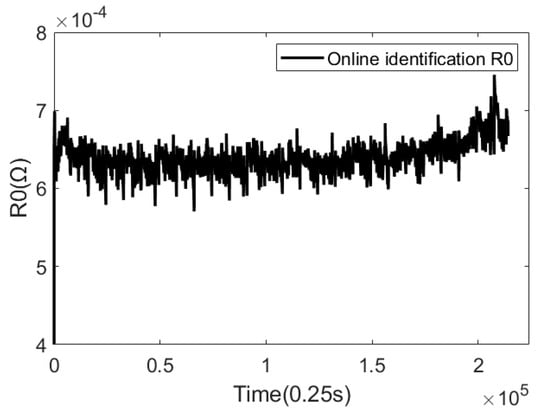
Figure 15.
Identification result graph of R0.
4.3. Verification of Joint SOC and SOH Estimation of the Overall Scheme
The results of the joint estimation are shown in Figure 16. From the SOC results, it can be seen that the SOC estimation results are close to the true value, with an average error of less than 2% and a maximum error of less than 5%, which meets the accuracy requirements. The results of R0 estimation are relatively stable. When SOC reaches the low SOC range, the internal resistance tends to increase, which is in accordance with the SOC variation rule of internal resistance. It can be seen from the estimated results of C1 that due to the fixed value of R1, C1 is constantly adjusted to correct the polarization voltage drop, and C1 shows an overall upward trend. As can be seen from the capacity estimation results, when the initial value is 90 Ah, the capacity can be adjusted back to near the actual capacity, the final estimated capacity is 113.21 Ah, the corresponding SOH is 98.44%, and the error is less than 2%, which meets the accuracy requirements.
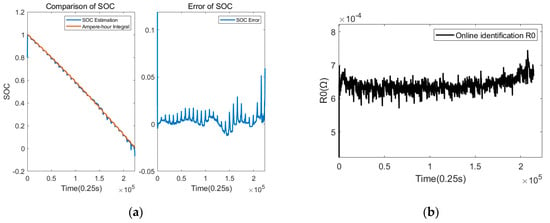
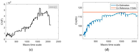
Figure 16.
Joint estimation of dynamic conditions. (a) Result of SOC estimation; (b) result of R0 estimation; (c) results of C1 estimation; (d) result of capacity estimation.
In the joint estimation scheme proposed in this paper, R1 is a fixed value, R0 is updated in real time through FFRLS on the micro-time scale, and C1 and capacity are estimated on the macro-time scale. Before fixing this scheme, a variety of schemes were proposed to update the following four parameters: R0, R1, C1 and capacity. This part shows the advantages of these schemes by comparing the estimation effects of these schemes on SOC and capacity. In Scheme 1, R0, R1 and C1 are updated in real time through FFRLS on a micro-time scale, and the capacity is estimated on a macro-time scale. In Scheme 2, R0 and R1 are updated in real time on a micro-time scale through FFRLS, and C1 and capacity are estimated on a macro-time scale. In Scheme 3, R0 is updated in real time on a micro-time scale through FFRLS, and R1, C1 and capacity are estimated on a macro-time scale. The SOC estimation error and capacity estimation error are quantified, as shown in Table 1. Combined with Figure 17, the SOC estimation results of Scheme 1 are highly accurate because battery parameters are calculated using FFRLS. Although FFRLS can ensure the accuracy of the fitting of the terminal voltage, it cannot accurately estimate the values of R1 and C1, resulting in a loss of callback characteristics of capacity estimation. In Scheme 2, R1 is updated in real time through FFRLS, but due to the large fluctuation in the update of R1 on the micro-time scale, C1 is a slow variable on the macro-time scale. The inconsistency of the R1 and C1 time scales leads to poor SOC estimation results, and the capacity cannot be adjusted back to the true value. In Scheme 3, both R1 and C1 are estimated by the macro-time-scale estimator. However, due to the large difference between the R1 order of magnitude and between C1 and capacity, the adaptive algorithm will lead to noise updating errors in R1, which will affect the estimation of SOC and SOH and lead to the estimation result of SOC being the worst. The SOC and SOH estimation accuracy of the proposed scheme is high, meeting the accuracy requirements.

Table 1.
Estimation errors of SOC and SOH.
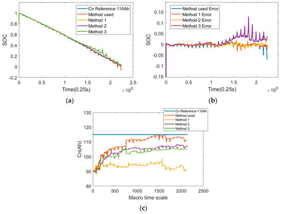
Figure 17.
Comparison of SOC and SOH estimation results of different schemes. (a) Comparison of SOC estimates; (b) comparison of SOC estimation error; (c) estimation result of capacity.
4.4. Verification of Multi-Temperature and Multi-Condition Joint Estimation Scheme
The adaptability of the estimation scheme was verified using the measured data of a set of 5.2 Ah batteries at multiple temperature points and under different driving conditions. The temperatures are −10 °C, 0 °C, 25 °C and 45 °C. The driving conditions are NEDC and WLTC. The estimated results are shown in Figure 18, Figure 19, Figure 20 and Figure 21. In combination with Table 2, it can be seen that the capacity estimation results under NEDC and WLTC conditions are consistent at the same temperature; the SOH estimation results under different temperatures and driving conditions are close, both at about 99.5%, and the relative capacity error is less than 1%. The average error of SOC estimation at all temperatures is less than 1.5%, and the maximum error is less than 2.02%, so the SOC estimation accuracy meets the requirements. It can be seen that the joint SOC and SOH estimation algorithm can quickly and accurately estimate the battery capacity, obtain a stable battery SOH value, and ensure high SOC estimation accuracy.
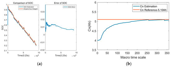
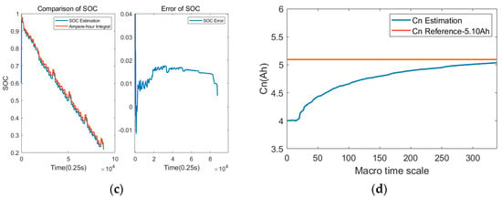
Figure 18.
Joint estimation results of dynamic driving conditions at −10 °C. (a) SOC estimation results and errors under NEDC driving conditions; (b) capacity estimation results under NEDC driving conditions; (c) SOC estimation results and errors under WLTC driving conditions; (d) capacity estimation results under WLTC driving conditions.
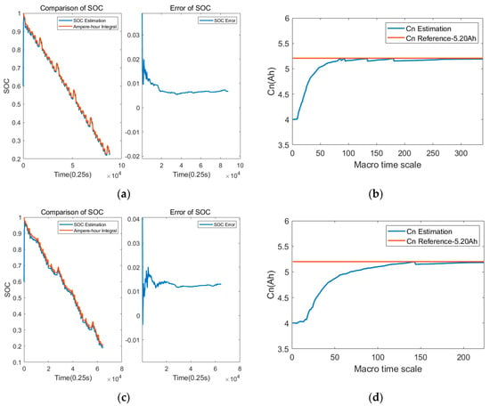
Figure 19.
Joint estimation results of dynamic driving conditions at 0 °C. (a) SOC estimation results and errors under NEDC driving conditions; (b) capacity estimation results under NEDC driving conditions; (c) SOC estimation results and errors under WLTC driving conditions; (d) capacity estimation results under WLTC driving conditions.
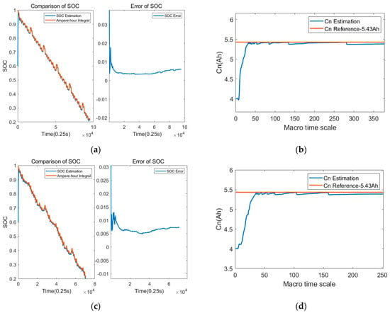
Figure 20.
Joint estimation results of dynamic driving conditions at 25 °C. (a) SOC estimation results and errors under NEDC driving conditions; (b) capacity estimation results under NEDC driving conditions; (c) SOC estimation results and errors under WLTC driving conditions; (d) capacity estimation results under WLTC driving conditions.
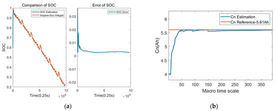
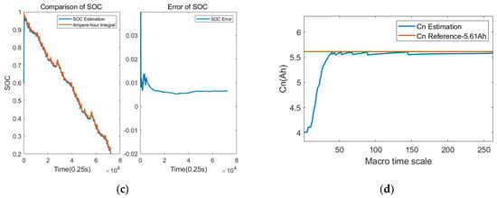
Figure 21.
Joint estimation results of dynamic driving conditions at 45 °C. (a) SOC estimation results and errors under NEDC driving conditions; (b) capacity estimation results under NEDC driving conditions; (c) SOC estimation results and errors under WLTC driving conditions; (d) capacity estimation results under WLTC driving conditions.

Table 2.
Comparison of multi-temperature and multi-condition estimation results.
5. Conclusions
The accurate estimation of SOC and SOH is important for the reliability of battery operation. In this paper, the OCV identification accuracy is improved by constructing the OCV under dynamic conditions. A multi-time-scale battery state joint estimation scheme was designed by considering the fast–slow variation characteristics of battery parameters and states, and its feasibility and reliability were verified via simulations and experiments. The main conclusions are as follows:
- (1)
- Based on ECM, FFRLS can accurately solve R0 and OCV in the time domain using the principle of differential discretization and recursive calculation. For R1 and C1 in the polarization stage, it is necessary to combine the slow-changing characteristics of the battery polarization voltage, and use data-driven and macro-time-scale AEKF to accurately solve them.
- (2)
- The DAEKF algorithm is suitable for constructing micro-time-scale SOC estimation and its recursive calculation relationship with macro-time-scale SOH estimation. With the appropriate selection of calculation steps, SOH can have a relatively balanced convergence speed and estimation accuracy under different temperature conditions. Meanwhile, based on the correlation calculation relationship between SOC and SOH, once the convergence of SOH regression is confirmed, it also proves the estimation accuracy of SOC.
- (3)
- There is a significant numerical difference between R1 and C1 in the polarization process, which makes it unsuitable to perform adaptive calculations on both in the same AEKF process. In this paper, the average value of R1 under small current excitation is first determined, and then the noise covariance of C1 is adaptively adjusted using a macroscopic time scale, which can compensate for the noise introduced due to model inaccuracy.
Further research will be carried out to verify other large-capacity batteries, and the joint SOC and SOH estimation method will be optimized in combination with the internal temperature estimation of cells.
Author Contributions
Conceptualization, A.L.; methodology, Y.L.; writing—original draft preparation, T.H.; writing—review and editing, C.Y.; software, T.H.; funding acquisition, Y.Y. All authors have read and agreed to the published version of the manuscript.
Funding
This research was funded by Jilin Province Science and Technology Development Program of China, grant number 20210301020GX.
Data Availability Statement
The raw data supporting the conclusions of this article will be made available by the authors on request.
Conflicts of Interest
Yixin Liu, Ao Lei, and Chunyang Yu are employees of China FAW Group Co., Ltd. This paper reflects the views of the scientists, and not the company. The authors declare no conflicts of interest.
References
- Khan, F.N.U.; Rasul, M.G.; Sayem, A.S.M.; Mandal, N.K. Design and optimization of lithium-ion battery as an efficient energy storage device for electric vehicles: A comprehensive review. J. Energy Storage 2023, 71, 108033. [Google Scholar] [CrossRef]
- Chen, Y.; Li, R.; Sun, Z.; Zhao, L.; Guo, X. SOC estimation of retired lithium-ion batteries for electric vehicle with improved particle filter by H-infinity filter. Energy Rep. 2023, 9, 1937–1947. [Google Scholar] [CrossRef]
- Wang, Z.; Feng, G.; Zhen, D.; Gu, F.; Ball, A. A review on online state of charge and state of health estimation for lithium-ion batteries in electric vehicles. Energy Rep. 2021, 7, 5141–5161. [Google Scholar] [CrossRef]
- Zhang, R.; Li, X.; Sun, C.; Yang, S.; Tian, Y.; Tian, J. State of Charge and Temperature Joint Estimation Based on Ultrasonic Reflection Waves for Lithium-Ion Battery Applications. Batteries 2023, 9, 335. [Google Scholar] [CrossRef]
- Xu, J.; Sun, C.; Ni, Y.; Lyu, C.; Wu, C.; Zhang, H.; Yang, Q.; Feng, F. Fast Identification of Micro-Health Parameters for Retired Batteries Based on a Simplified P2D Model by Using Padé Approximation. Batteries 2023, 9, 64. [Google Scholar] [CrossRef]
- Li, X.; Wang, Z.; Zhang, L. Co-estimation of capacity and state-of-charge for lithium-ion batteries in electric vehicles. Energy 2019, 174, 33–44. [Google Scholar] [CrossRef]
- Shen, P.; Ouyang, M.; Lu, L.; Li, J.; Feng, X. The Co-estimation of State of Charge, State of Health, and State of Function for Lithium-Ion Batteries in Electric Vehicles. IEEE Trans. Veh. Technol. 2017, 99, 92–103. [Google Scholar]
- Xing, Y.; He, W.; Pecht, M.; Tsui, K.L. State of charge estimation of lithium-ion batteries using the open-circuit voltage at various ambient temperature. Appl. Energy 2014, 113, 106–115. [Google Scholar] [CrossRef]
- Yang, N.; Zhang, X.; Li, G. State of charge estimation for pulse discharge of a LiFePO4 battery by a revised Ah counting. Electrochim. Acta 2015, 151, 63–71. [Google Scholar] [CrossRef]
- Dong, G.; Chen, Z.; Wei, J.; Ling, Q. Battery health prognosis using Brownian motion modeling and particle filtering. IEEE Trans. Ind. Electron. 2018, 65, 8646–8655. [Google Scholar] [CrossRef]
- Zeng, M.; Zhang, P.; Yang, Y.; Xie, C.; Shi, Y. SOC and SOH joint estimation of the power batteries based on fuzzy unscented Kalman filtering algorithm. Energies 2019, 12, 3122. [Google Scholar] [CrossRef]
- Wen, J.; Chen, X.; Li, X.; Li, Y. SOH prediction of lithium battery based on IC curve feature and BP neural network. Energy 2022, 261, 125234. [Google Scholar] [CrossRef]
- Lee, C.J.; Kim, B.K.; Kwon, M.K.; Nam, K.; Kang, S.W. Real-time prediction of capacity fade and remaining useful life of lithium-ion batteries based on charge/discharge characteristics. Electronics 2021, 10, 846. [Google Scholar] [CrossRef]
- Guo, F.; Hu, G.; Xiang, S.; Zhou, P.; Hong, R.; Xiong, N. A multi-scale parameter adaptive method for state of charge and parameter estimation of lithium-ion batteries using dual Kalman filters. Energy 2019, 178, 79–88. [Google Scholar] [CrossRef]
- Zhang, S.; Guo, X.; Zhang, X. A novel one-way transmitted co-estimation framework for capacity and state-of-charge of lithium-ion battery based on double adaptive extended Kalman filters. J. Energy Storage 2021, 33, 102093. [Google Scholar]
- Arora, S.; Shen, W.; Kapoor, A. Critical analysis of open circuit voltage and its effect on estimation of irreversible heat for Li-ion pouch cells. J. Power Sources 2017, 350, 117–126. [Google Scholar] [CrossRef]
- Yun, X.; Zhang, X.; Wang, C.; Fan, X. Online parameters identification and state of charge estimation for lithium-ion batteries based on improved central difference particle filter. J. Energy Storage 2023, 70, 107987. [Google Scholar] [CrossRef]
- Zheng, Y.; Cui, Y.; Han, X.; Dai, H.; Ouyang, M. Lithium-ion battery capacity estimation based on open circuit voltage identification using the iteratively reweighted least squares at different aging levels. J. Energy Storage 2021, 44, 103487. [Google Scholar] [CrossRef]
- Dai, H.; Xu, T.; Zhu, L.; Wei, X.; Sun, Z. Adaptive model parameter identification for large capacity Li-ion batteries on separated time scales. Appl. Energy 2016, 184, 119–131. [Google Scholar] [CrossRef]
- Li, H.; Zhang, W.; Yang, X.; Jiang, H.; Wang, Y.; Yang, T.; Chen, L.; Shen, H. State of charge estimation for lithium-ion battery using an electrochemical model based on electrical double layer effect. Electrochim. Acta 2019, 326, 134966. [Google Scholar] [CrossRef]
- Li, W.; Fan, Y.; Ringbeck, F.; Jöst, D.; Han, X.; Ouyang, M.; Sauer, D.U. Electrochemical model-based state estimation for lithium-ion batteries with adaptive unscented Kalman filter. J. Power Sources 2020, 476, 228534. [Google Scholar] [CrossRef]
- Tian, J.; Xiong, R.; Shen, W.; Wang, J.; Yang, R. Online simultaneous identification of parameters and order of a fractional order battery model. J. Clean. Prod. 2020, 247, 119147. [Google Scholar] [CrossRef]
- Guo, R.; Shen, W. Online state of charge and state of power co-estimation of lithium-ion batteries based on fractional-order calculus and model predictive control theory. Appl. Energy 2022, 327, 120009. [Google Scholar] [CrossRef]
- Pai, H.Y.; Liu, Y.H.; Ye, S.P. Online estimation of lithium-ion battery equivalent circuit model parameters and state of charge using time-domain assisted decoupled recursive least squares technique. J. Energy Storage 2023, 62, 106901. [Google Scholar] [CrossRef]
- Tran, M.-K.; Mathew, M.; Janhunen, S.; Panchal, S.; Raahemifar, K.; Fraser, R.; Fowler, M. A comprehensive equivalent circuit model for lithium-ion batteries, incorporating the effects of state of health, state of charge, and temperature on model parameters. J. Energy Storage 2021, 43, 103252. [Google Scholar] [CrossRef]
Disclaimer/Publisher’s Note: The statements, opinions and data contained in all publications are solely those of the individual author(s) and contributor(s) and not of MDPI and/or the editor(s). MDPI and/or the editor(s) disclaim responsibility for any injury to people or property resulting from any ideas, methods, instructions or products referred to in the content. |
© 2024 by the authors. Licensee MDPI, Basel, Switzerland. This article is an open access article distributed under the terms and conditions of the Creative Commons Attribution (CC BY) license (https://creativecommons.org/licenses/by/4.0/).