Magnetic Resonance Imaging-Compatible Electromagnetic Actuator: Design and Tests
Abstract
1. Introduction
2. Materials and Methods
2.1. MRI-Compatible Electromagnetic Motor Design Principle
2.2. Analytical Electromagnetic Model
2.3. 3D Electromagnetic Model Validation
2.4. Design Optimization
- The outer radius should be less than 1.5 cm.
- By considering the width of the winding , the total length of the actuator (Equation (14)) should be less than 5 cm.
- The mean radius R should be higher than .
- The cross section of the wire is set to be higher than 0.01 mm2, which is the smallest available wire section. It is given by
- The diameter of the wire should be less than the width of the coil. It can be calculated by the following equation
- The RMS value of the current density is less than 3 A/mm2 in order to limit the heating of the wires.
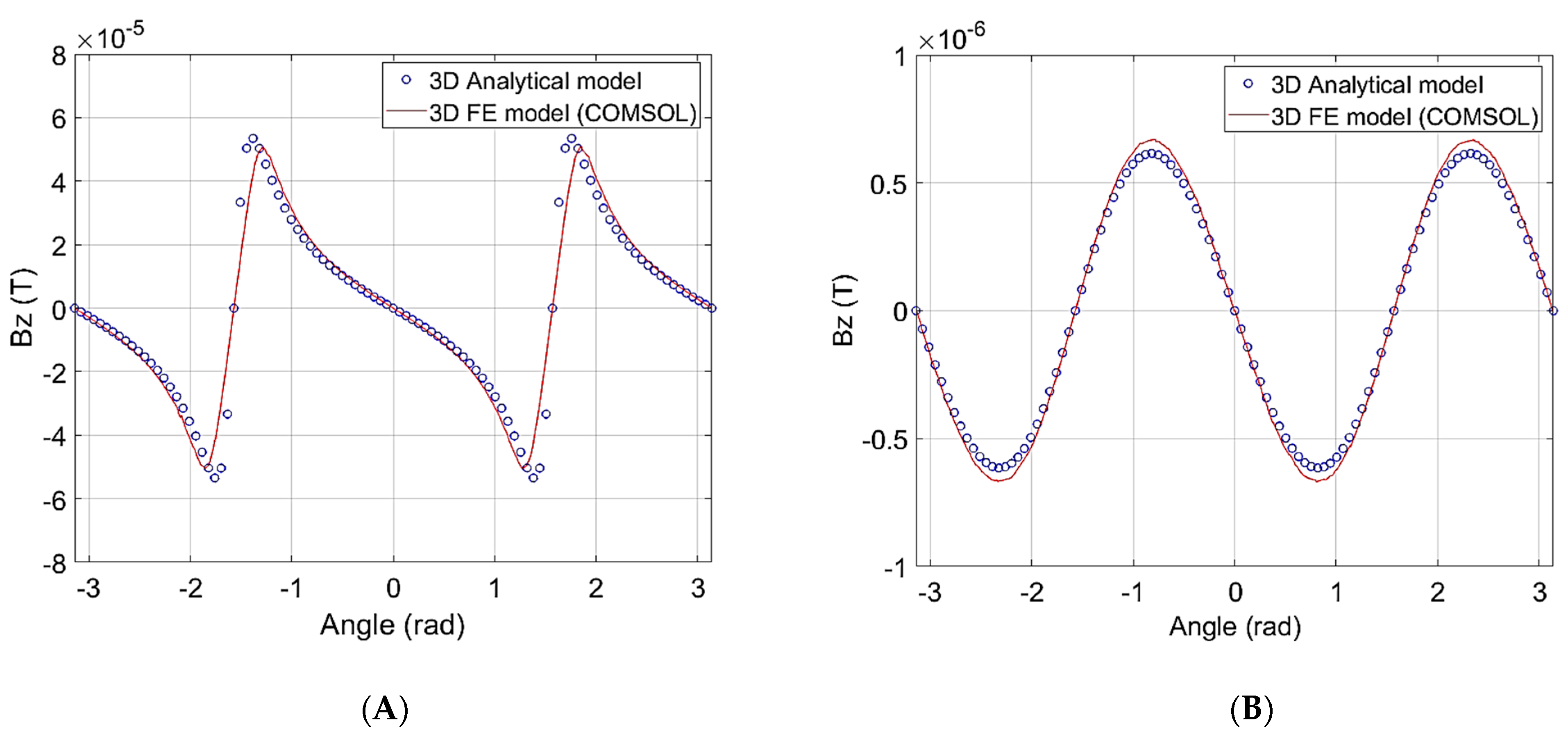
- To avoid disturbing the homogeneity of the MRI magnetic field B0, the z-component of the magnetic field created by the actuator should be less than 1 μT.
2.5. Optimization Results
2.6. Realisation of the Designed Actuator
2.7. Design and Realisation of the Control Circuit
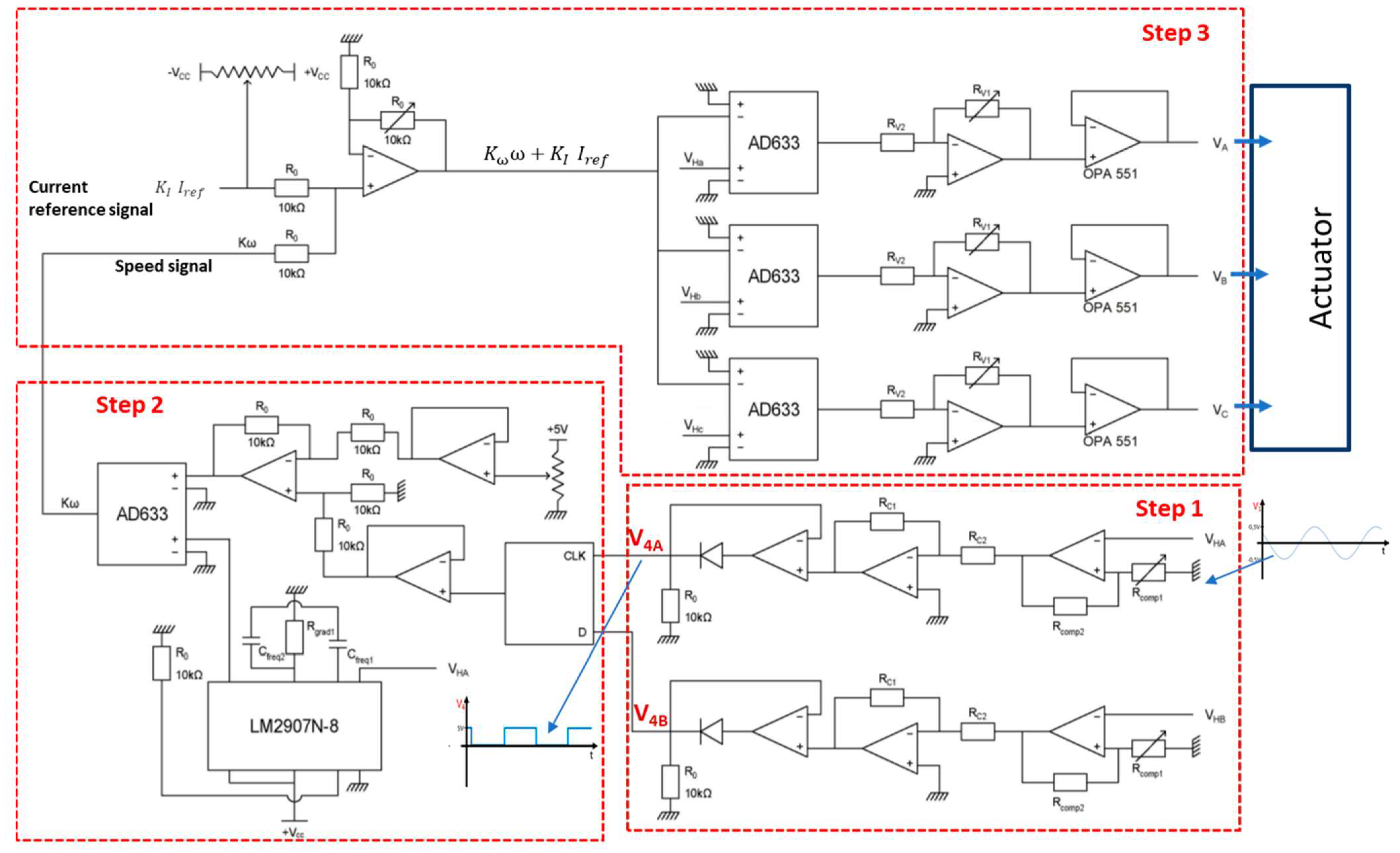
- Step 1: It consists of obtaining an image signal of the direction of the rotor rotation issued from two Hall-effect sensors. For that, these signals are converted from sinusoidal signals varying between −0.5 V and 0.5 V to square signals varying between 0 V and 5 V. In this case, a hysteresis comparator is used to obtain square signals varying between −15 V and 15 V. Then, these signals are injected into an inverting operational amplifier with gain −1/3 in order to obtain square signals varying between −5 V and 5 V. After that, these signals are injected in a single-phase rectifier without threshold to obtain square signals varying between 0 V and 5 V.
- Step 2: Now, the obtained signals constitute an input data and D flip-flop clock which gives as outputs a voltage of 5 V when the rotor turns in the positive direction and 0 V otherwise. Then, this signal is shifted by −2.5 V in order to obtain an image signal of the direction of rotation taking the values −2.5 V or 2.5 V. This offset is carried out by subtracting a constant voltage of 2.5 V from this signal. Now, the image signal of the angular speed is obtained by multiplying the two signals (frequency image and rotor direction signal) using the analogue multiplier ADA633.
- Step 3: Once the signal of the voltage corresponding to the rotor speed is obtained, it is added to the voltage signal of the referenced current using the op amp assembly. In order to obtain a voltage varying with cos θ as indicated in Equation (19), we multiply this voltage by the voltage coming from the Hall effect sensor and injected into an amplifier to obtain the gain K as given in Equation (23). Then, this voltage is used as an input data of a follower assembly using the OPA 551 power AOP which can provide up to 200 mA. Finally, the three phase voltages are directly applied to the rotor windings.
2.8. MR Test Environments of the Actuator
2.8.1. MR System Rated B0 = 0.3 T
2.8.2. MRI Research Scanner (B0 = 2.34 T)
- MR image sequences
- 2
- Actuator imaging protocol
3. Results and Discussion
3.1. Electrical Parameters of the Actuator
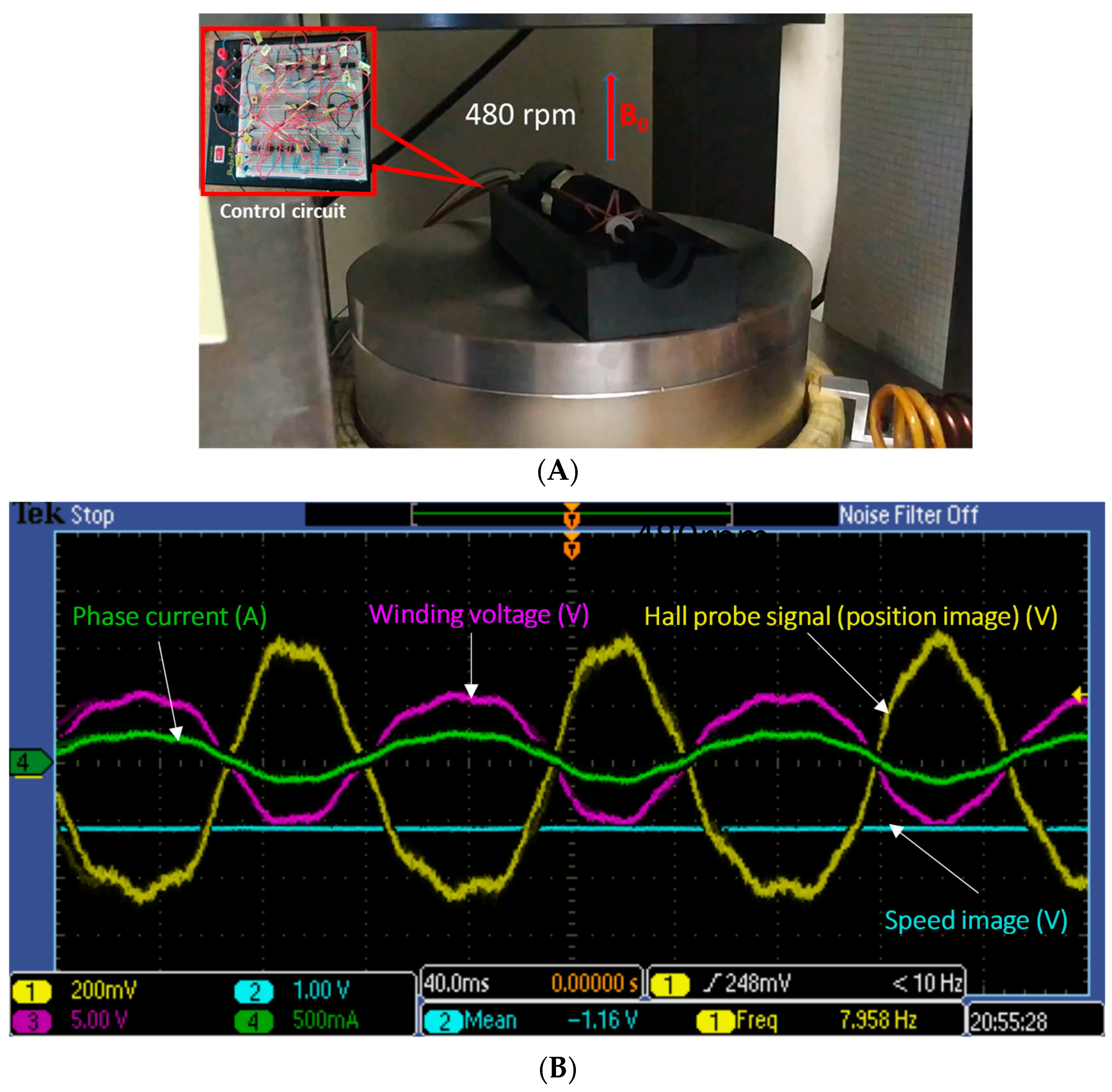
3.2. Generator Mode Operation
3.3. Motor Mode Operation
3.4. MRI Image Analysis
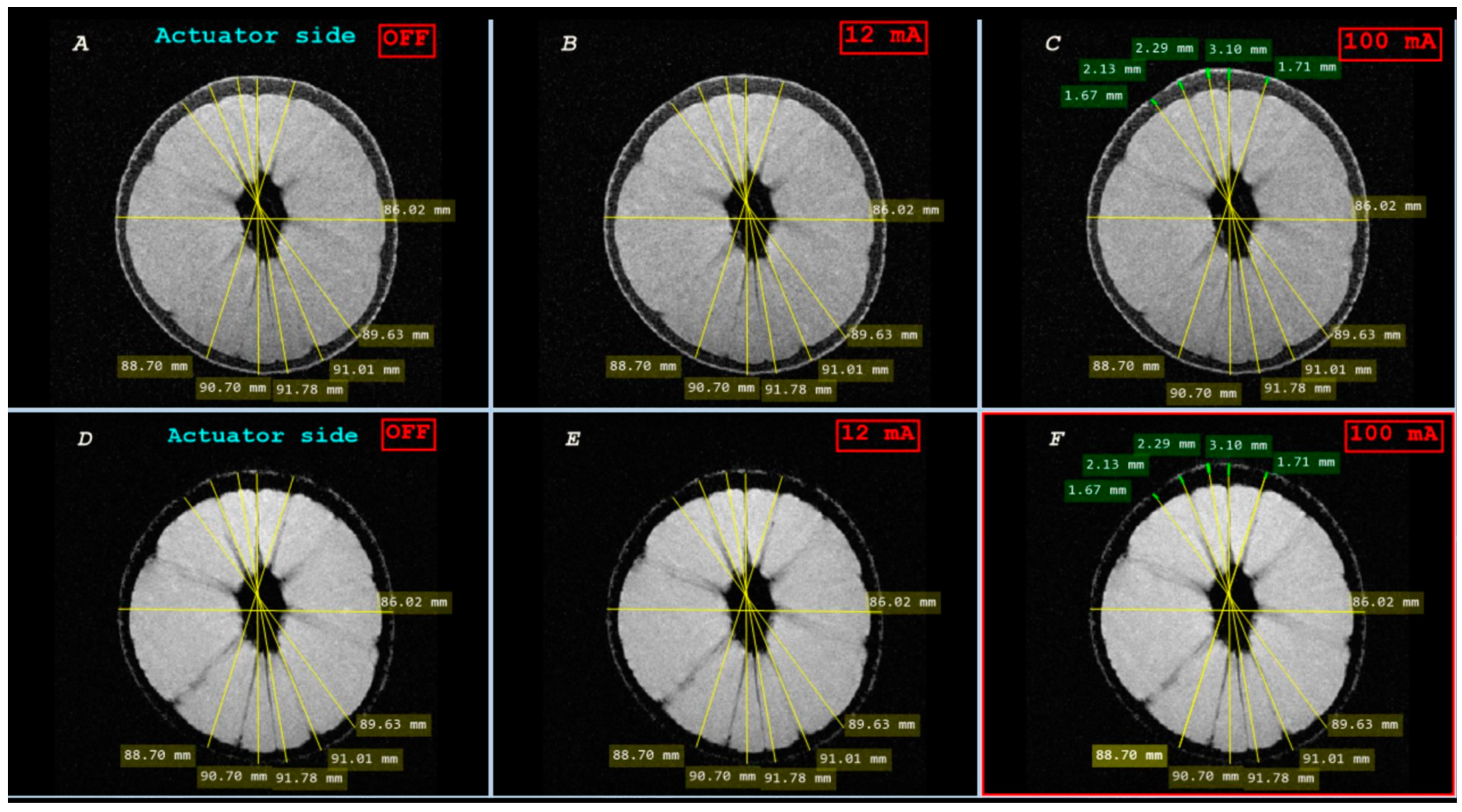
3.4.1. Geometric Distortion Artefact
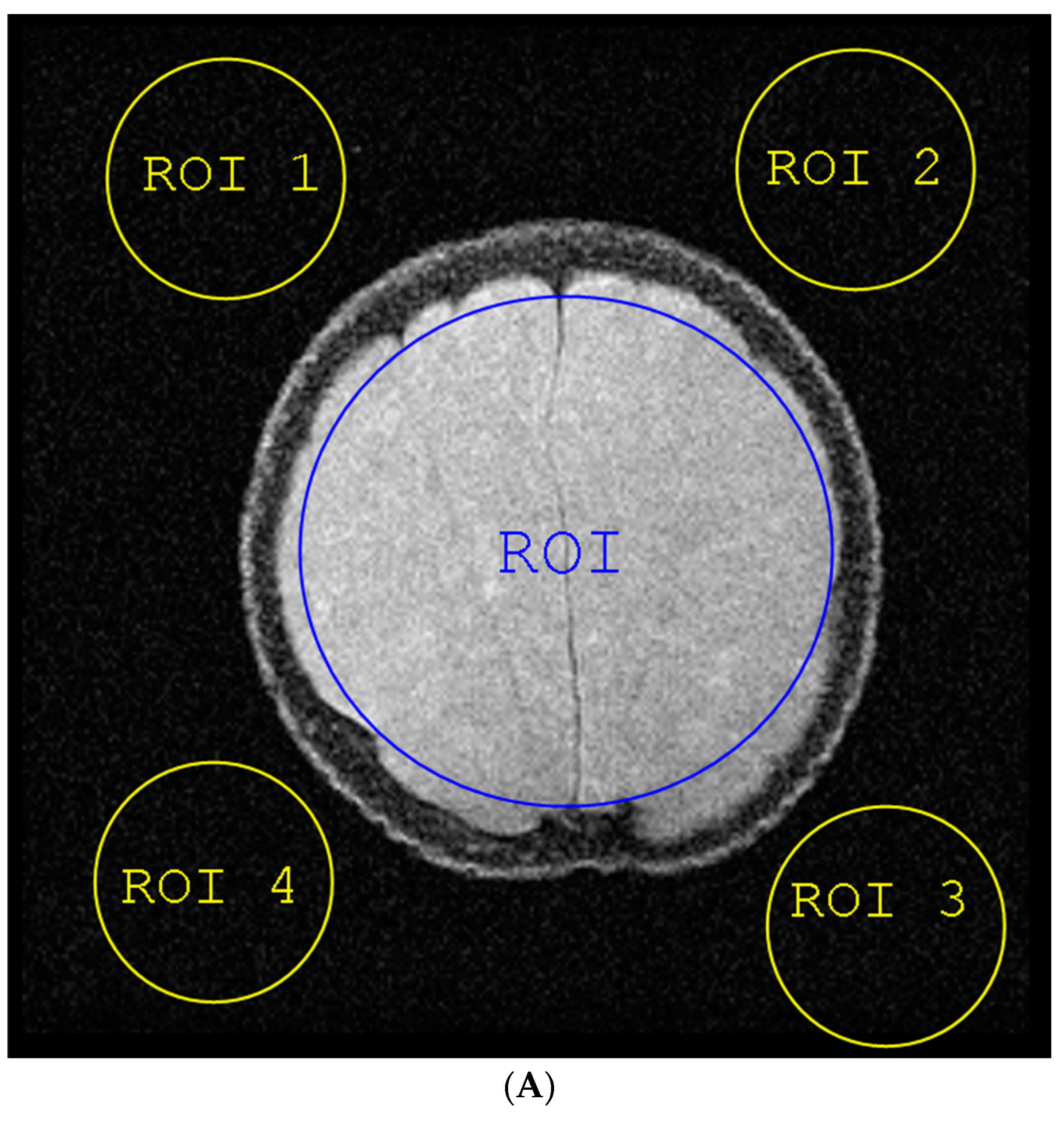
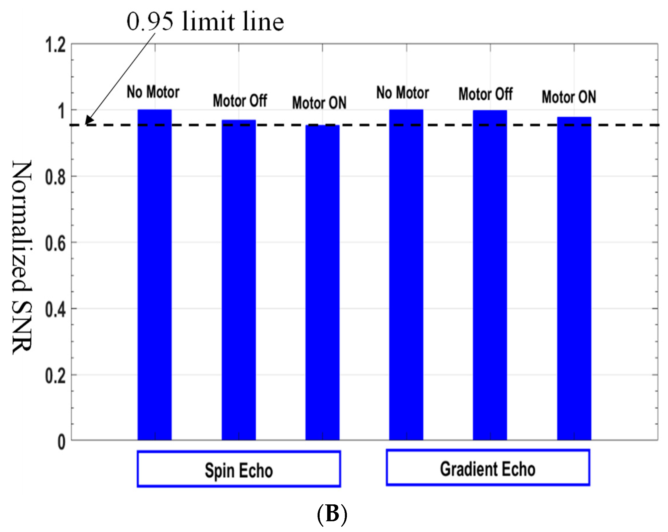
3.4.2. Signal-to-Noise Ratio (SNR)
- (1)
- The average pixel’s intensities of a region-of-interest (ROI 1) of the image covering about 80% of the region producing the entire signal. This provides a satisfactory measure of the NMR signal level.
- (2)
- The standard deviation of the pixels in four (ROI) in the over-scan area of the image that was dominated by noise to estimate the noise level [22].
4. Conclusions
Author Contributions
Funding
Data Availability Statement
Conflicts of Interest
References
- Gassert, R.; Yamamoto, A.; Chapuis, D.; Dovat, L.; Bleuler, H.; Burdet, E. Actuation methods for applications in MR environments. Concepts Magn. Reson. Part B 2006, 29 Pt B, 191–209. [Google Scholar] [CrossRef]
- Fischer, G.S.; Krieger, A.; Iordachita, I.; Csoma, C.; Whitcomb, L.L.; Gabor, F. MRI compatibility of robot actuation techniques—A comparative study. Med. Image Comput. Assist. Interv. 2008, 11 Pt 2, 509–517. [Google Scholar] [CrossRef]
- Liang, H.; Tse, Z.T.H. An Opposed Piston Driving Pneumatic Stepper Motor for MR Intervention Robotics. IEEE/ASME Trans. Mechatron. 2023, 29, 143–153. [Google Scholar] [CrossRef]
- Goldenberg, A.A.; Trachtenberg, J.; Kucharczyk, W.; Yi, Y.; Haider, M.; Ma, L.; Weersink, R.; Raoufi, C. Robotic System for Closed-Bore MRI-Guided Prostatic Interventions. IEEE/ASME Trans. Mechatron. 2008, 13, 374–379. [Google Scholar] [CrossRef]
- Tsekos, N.V.; Özcan, A.; Christoforou, E. A prototype manipulator for magnetic resonance-guided interventions inside standard cylindrical magnetic resonance imaging scanners. J. Biomech. Eng. 2005, 127, 972–980. [Google Scholar] [CrossRef] [PubMed]
- Krieger, A.; Song, S.-E.; Cho, N.B.; Iordachita, I.I.; Guion, P.; Fichtinger, G.; Whitcomb, L.L. Development and Evaluation of an Actuated MRI-Compatible Robotic System for MRI-Guided Prostate Intervention. IEEE/ASME Trans. Mechatron. 2013, 18, 273–284. [Google Scholar] [CrossRef] [PubMed]
- Elhawary, H.; Zivanovic, A.; Rea, M.; Davies, B.; Besant, C.; McRobbie, D.; de Souza, N.; Young, I.; Lampérth, M. The Feasibility of MR-Image Guided Prostate Biopsy Using Piezoceramic Motors Inside or Near to the Magnet Isocentre. In Medical Image Computing and Computer-Assisted Intervention—MICCAI 2006; Larsen, R., Nielsen, M., Sporring, J., Eds.; Springer: Berlin/Heidelberg, Germany, 2006; pp. 519–526. [Google Scholar]
- Kapoor, A.; Wood, B.; Mazilu, D.; Horvath, K.A.; Li, M. MRI-compatible hands-on cooperative control of a pneumatically actuated robot. In Proceedings of the 2009 IEEE International Conference on Robotics and Automation, Kobe, Japan, 12–17 May 2009; pp. 2681–2686. [Google Scholar] [CrossRef]
- Liang, H.; Tse, Z.T.H. Cycloidal Stepper Motor: A Systematic Approach for Designing a Nonmagnetic Rotary Actuator. IEEE/ASME Trans. Mechatron. 2023, 28, 71–79. [Google Scholar] [CrossRef]
- Groenhuis, V.; Siepel, F.J.; Stramigioli, S. Magnetic Resonance Pneumatic Stepper Motor with Multiple Concentric Shafts Output. IEEE/ASME Trans. Mechatron. 2022, 27, 2379–2389. [Google Scholar] [CrossRef]
- Li, G.; Su, H.; Cole, G.A.; Shang, W.; Harrington, K.; Camilo, A.; Pilitsis, J.G.; Fischer, G.S. Robotic System for MRI-Guided Stereotactic Neurosurgery. IEEE Trans. Biomed. Eng. 2015, 62, 1077–1088. [Google Scholar] [CrossRef] [PubMed]
- Yang, B.; Tan, U.-X.; McMillan, A.B.; Gullapalli, R.; Desai, J.P. Design and Control of a 1-DOF MRI-Compatible Pneumatically Actuated Robot with Long Transmission Lines. IEEE/ASME Trans. Mechatron. 2011, 16, 1040–1048. [Google Scholar] [CrossRef] [PubMed]
- Yamamoto, A.; Ichiyanagi, K.; Higuchi, T.; Imamizu, H.; Gassert, R.; Ingold, M.; Sache, L.; Bleuler, H. Evaluation of MR-compatibility of Electrostatic Linear Motor. In Proceedings of the 2005 IEEE International Conference on Robotics and Automation, Barcelona, Spain, 18–22 April 2005; pp. 3658–3663. [Google Scholar] [CrossRef]
- Vartholomeos, P.; Bergeles, C.; Qin, L.; Dupont, P.E. An MRI-powered and controlled actuator technology for tetherless robotic interventions. Int. J. Robot. Res. 2013, 32, 1536–1552. [Google Scholar] [CrossRef]
- Mutlu, S.; Yasa, O.; Erin, O.; Sitti, M. Magnetic Resonance Imaging-Compatible Optically Powered Miniature Wireless Modular Lorentz Force Actuators. Adv. Sci. 2021, 8, 202002948. [Google Scholar] [CrossRef]
- Hofstetter, L.W.; Hadley, J.R.; Merrill, R.; Pham, H.; Fine, G.C.; Parker, D.L. MRI-compatible electromagnetic servomotor for image-guided medical robotics. Commun. Eng. 2022, 1, 4. [Google Scholar] [CrossRef] [PubMed]
- Chauviere, S.; Belguerras, L.; Lubin, T.; Mezani, S. Design and Test of an Open Portable MRI System. COMPEL-Int. J. Comput. Math. Electr. Electron. Eng. 2022, 41, 1084–1095. [Google Scholar] [CrossRef]
- Available online: https://www.smbbearings.com/products/zro2-ceramic-bearings.html (accessed on 25 March 2023).
- Available online: https://www.chenyang-gmbh.com/en/hall-effect-elements-ics/linear-hall-sensor-elements.html (accessed on 21 May 2023).
- Available online: https://www.rotarx.com/en/slip-rings/separate-slip-rings/ (accessed on 5 February 2023).
- Medixant. RadiAnt DICOM Viewer (Version 2022.1) [Software]. Available online: https://www.radiantviewer.com (accessed on 17 June 2022).
- Dietrich, O.; Raya, J.G.; Reeder, S.B.; Reiser, M.F.; Schoenberg, S.O. Measurement of signal-to-noise ratios in MR images: Influence of multichannel coils, parallel imaging, and reconstruction filters. J. Magn. Reson. Imaging 2007, 26, 375–385. [Google Scholar] [CrossRef]






| Symbol | Quantity | Value |
|---|---|---|
| p | Number of pole pairs | 1 |
| R | Outer radius | 10 mm |
| L | Active axial length | 50 mm |
| N | Number of turns | 1 |
| I | Total current | 1 A |
| Parameter | Min Value | Max Value | Unit |
|---|---|---|---|
| 0 | 1.5 | cm | |
| 0 | 5 | cm | |
| 0 | 100 | - | |
| 0 | 0.1 | A | |
| 0 | 1 | - | |
| 0 | 1.5 | cm |
| Constraint | Designation |
|---|---|
| C1 | |
| C2 | |
| C3 | |
| C4 | |
| C5 | |
| C6 |
| Parameter | Value | Unit |
|---|---|---|
| 1.4 | cm | |
| 4.9 | cm | |
| 60 | - | |
| 12 | mA | |
| 0.1 | - | |
| 1 | mm |
| Inductances | Measured (µH) | Calculated (µH) |
|---|---|---|
| La | 355 | 363 |
| Lb | 361 | 363 |
| Lc | 360 | 363 |
| Mab | −59.2 | −59.2 |
Disclaimer/Publisher’s Note: The statements, opinions and data contained in all publications are solely those of the individual author(s) and contributor(s) and not of MDPI and/or the editor(s). MDPI and/or the editor(s) disclaim responsibility for any injury to people or property resulting from any ideas, methods, instructions or products referred to in the content. |
© 2024 by the authors. Licensee MDPI, Basel, Switzerland. This article is an open access article distributed under the terms and conditions of the Creative Commons Attribution (CC BY) license (https://creativecommons.org/licenses/by/4.0/).
Share and Cite
Chauvière, S.; Belguerras, L.; Lubin, T.; Mezani, S.; Leclerc, S.; Guendouz, L. Magnetic Resonance Imaging-Compatible Electromagnetic Actuator: Design and Tests. Energies 2024, 17, 3254. https://doi.org/10.3390/en17133254
Chauvière S, Belguerras L, Lubin T, Mezani S, Leclerc S, Guendouz L. Magnetic Resonance Imaging-Compatible Electromagnetic Actuator: Design and Tests. Energies. 2024; 17(13):3254. https://doi.org/10.3390/en17133254
Chicago/Turabian StyleChauvière, Simon, Lamia Belguerras, Thierry Lubin, Smail Mezani, Sébastien Leclerc, and Laoues Guendouz. 2024. "Magnetic Resonance Imaging-Compatible Electromagnetic Actuator: Design and Tests" Energies 17, no. 13: 3254. https://doi.org/10.3390/en17133254
APA StyleChauvière, S., Belguerras, L., Lubin, T., Mezani, S., Leclerc, S., & Guendouz, L. (2024). Magnetic Resonance Imaging-Compatible Electromagnetic Actuator: Design and Tests. Energies, 17(13), 3254. https://doi.org/10.3390/en17133254


