Article

Sensorless Capability Expansion for SPMSM Based on Inductance Parameter Identification

School of Automation, Northwestern Polytechnical University, Xi’an 710072, China
*
Author to whom correspondence should be addressed.
Energies 2024, 17(13), 3219; https://doi.org/10.3390/en17133219
Submission received: 23 May 2024 / Revised: 26 June 2024 / Accepted: 28 June 2024 / Published: 30 June 2024

Abstract

:
Pulsating high-frequency voltage injection can be used for the sensorless control of a surface-mounted permanent magnet synchronous motor (SPMSM) at zero- and low-speed ranges. However, the sensorless capability still faces challenges to the requirements of industrial application, especially at heavy load status. Aiming at this issue, this article proposes a sensorless capability expansion method for an SPMSM based on inductance parameter identification. Firstly, incremental inductances at the d-q-axis and cross-coupling inductance are identified offline by three steps combining the rotating high-frequency voltage injection and pulsating high-frequency voltage injection. Using a polynomial curve fitting algorithm, apparent inductances are calculated. Secondly, positive DC current injection at the d-axis is proposed to enhance the saliency ratio based on the analysis of parameter identification results. Compared with the conventional i d = 0 or i d < 0 method, the saliency ratio is enhanced obviously when a positive DC current is injected at the d-axis. Then, the convergence region of the sensorless control method at heavy load status is expanded and the accuracy of rotor position estimation is improved using the proposed method. Finally, the experimental results validate that the sensorless capability of the SPMSM is expanded.

1. Introduction

Permanent magnet synchronous motors (PMSMs) are widely used for industry applications due to their high power density, high torque density and high efficiency. Sensorless control of PMSMs is an interesting topic for researchers in recent decades [1]. Once the position sensor is removed, the cost is reduced. Meanwhile, the reliability is improved because the additional cables are not needed anymore.
Sensorless control methods for PMSMs can be divided into two categories. The first category is the model-based method. When the motor is operating at medium- and high-speed ranges, the rotor position can be estimated by the back electromotive force (EMF) [2]. The second category is the saliency-based method [3]. By injecting high-frequency (HF) voltage into the motor, the saliency effect can be used for rotor position estimation at zero- and low-speed ranges.
Among the three typical HF voltage injection methods, the accuracy of position estimation is low for the rotating high-frequency voltage injection method [4] The phase delay is small for the high-frequency square-wave voltage injection method. However, high switching frequency leads to high noise and high loss [5]. Compared with the two methods above, the pulsating high-frequency voltage injection method has the advantages of high accuracy and good stability [6]; it has been gradually promoted for industrial applications.
Although the pulsating high-frequency voltage injection method can be used for sensorless control of SPMSMs, the sensorless capability still faces challenges to the requirements of the actual application. It is very necessary to investigate the limitation of the saliency-based sensorless control method [7,8,9,10]. Sensorless capabilities are comprised of the saliency ratio, estimation error, and convergence region [7,8]. When pulsating high-frequency voltage injection is used for the sensorless control of SPMSMs, it is found that as the load increases, the saliency ratio decreases due to the saturation effect, and the convergence region of sensorless control is limited. The sensorless control method even fails at severe status. Meanwhile, due to the cross-coupling effect, the estimated rotor position gradually deviates from the actual rotor position, and the accuracy of position estimation is degraded [9,10]. Therefore, the research on sensorless capability expansion for SPMSMs at heavy load status is of great significance.
In order to expand the sensorless capability for PMSMs based on the saliency effect, extensive research has been carried out. The two main categories are motor body design optimization and motor control improvement. In the first category, the motor design method is proposed to achieve self-sensing capability while retaining the torque-speed capability for PMSMs used in hybrid electric vehicles [11]. By adding a short-circuited rotor ring into the two-pole slotless permanent magnet motor, the saliency ratio is expanded to 1.8 [12]. An improved inductance model is proposed to reduce the torque ripple and enhance the self-sensing capabilities of PMSMs [13]. In the second category, using the current reference tilting strategy [14,15], the rotor position estimation error is reduced, and the torque limitation is expended. In [16], a new online method is proposed to detect and compensate the position estimation error due to the cross-coupling effect, and the accuracy of position estimation is improved.
Apart from the methods above, it is noticed that inductance parameter identification is an effective way to evaluate the sensorless capability of PMSMs based on the saliency effect [17]. The two kinds of inductances in the voltage equation of PMSMs are incremental inductance and apparent inductance. In [18,19], the finite element analysis method is used for the identification of incremental inductance parameters. However, the method is limited at the motor design process. In [20], driving the motor operating at a constant speed, the flux linkage versus current curve of the machine is constructed; then, incremental inductances are identified using partial differentiation calculation. In [21], when the rotor position is locked, the rotor speed term in the voltage equation is ignored, and incremental inductances are identified based on the simplified fundamental voltage equation. However, the common issue in [20,21] is that the computation of partial differentiation is large. High-frequency voltage injection is proposed for incremental inductance identification in [22,23]. However, cross-coupling inductance is ignored. In [24], incremental inductance and cross-coupling inductance are identified using the rotating high-frequency voltage injection method. In [25,26], with the assistant of a position sensor, high-frequency voltages are injected into the actual reference frame and the position observer is removed; the incremental inductance identification process is easy, and the accuracy can be guaranteed. In addition to the incremental inductances, apparent inductances are also important parameters in motor drive technology. In [20,21], apparent inductances are identified according to the flux linkage versus current curve of a PMSM. However, the inductance identification fails when the fundamental current is zero. Meanwhile, due to the saturation and cross-coupling effect, a non-linear relationship is observed between the flux linkage and current at the dq-axis. In [27], polynomial fitting is proposed to reduce the fitting error when the non-linear relationship between the amplitude of i d and the target torque is considered. In [28], second-order polynomial fitting is proposed to predict the current- and temperature-dependent behavior of a PMSM. In [29,30,31,32], a polynomial curve fitting algorithm is proposed for apparent inductance identification. Compared with the method in [20,21], the apparent inductances can be calculated even when the fundamental current is zero.
According to the analysis above, this article proposes a sensorless capability expansion method for an SPMSM based on inductance parameter identification. The incremental inductances at the d-q-axis and cross-coupling inductance are identified offline by combining the rotating high-frequency voltage injection and pulsating high-frequency voltage injection method in three steps. Then, a sixth-order polynomial curve fitting algorithm is proposed for apparent inductance identification. Based on the analysis of the offline inductance identification results, a positive DC current injection at the estimated d-axis is proposed to expand the sensorless capability of the SPMSM. Compared with the conventional i d = 0 or i d < 0 method, the saliency ratio is enhanced obviously, the guaranteed stable convergence region is expanded to 200% its rated load, and accuracy of the rotor position estimation is improved using the proposed method. Finally, the effectiveness of the proposed method is verified using a 200 W SPMSM.

2. Conventional Pulsating High-Frequency Voltage Injection

2.1. Incremental Inductance and Apparent Inductance

The voltage equation considering the cross-coupling effect involves multiple inductance parameters. Among them, incremental inductance is known as dynamic inductance, transient inductance, differential inductance, etc. Incremental inductance represents the slope at the operating point on the flux linkage–current curve, which is commonly used for small signal model analysis. The incremental inductances represent the dynamic behavior of the machine, for example, PI parameter tuning of the current control loop, inductance calculation in the high-frequency injection method, etc.
Apparent inductance is known as static inductance, absolute inductance, etc. It represents the ratio of magnetic flux to current. The inductance in the torque equation is apparent inductance. Figure 1 shows the difference between the incremental and apparent inductance. Due to the saturation effect, as the load increases, the incremental inductance is gradually less than the apparent inductance.

2.2. Conventional Pulsating High-Frequency Voltage Injection Method

The voltage equation of PMSM at d-q-axis is shown as
u d = i d R + L d i n c d i d d t + L d q i n c d i q d t ω e L q a p p i q u q = i q R + L q i n c d i q d t + L q d i n c d i d d t + ω e ( L d a p p i d + ψ P M )
where u d , u q , i d , i q , are the voltages and currents at the d-q-axis, R is the phase resistance, ω e is the rotor speed, L d i n c , L q i n c are incremental inductances at the d-q-axis, and L d q i n c , L q d i n c are the incremental cross-coupling inductances between the d-q-axis, and their values are equal. L d a p p , L q a p p are apparent inductances at the d-q-axis; ψ P M is the permanent magnet (PM) flux linkage.
The equivalent circuit diagram of the voltage equation of the PMSM at the dq-axis is shown in Figure 2.
Considering that the frequency of the voltage injected is much higher than the fundamental frequency and the motor is operating at zero- and low-speed range, the voltage drop of the resistance and the speed-related term in Equation (1) can be neglected. The HF model of PMSM is shown as
u d h u q h = L d i n c L d q i n c L d q i n c L q i n c d i d h d t d i q h d t
where u d h , u q h , i d h , i q h , are the HF voltages and currents at the d-q-axis.
For the pulsating high-frequency voltage injection method, the HF voltage is injected into the estimated d-axis:
u ^ d h u ^ q h = U h cos ω h t 0
where u ^ d h , u ^ q h are the HF voltages at the estimated the d-q-axis and U h , ω h are the amplitude and frequency of the injected voltage.
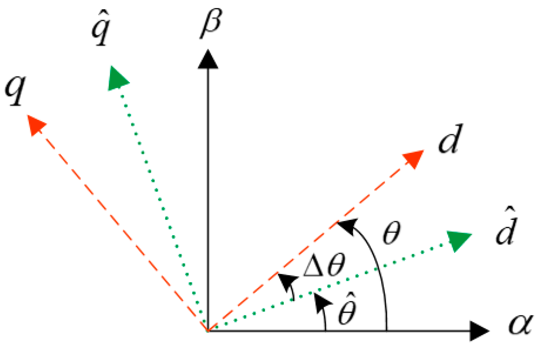
The rotor position and reference frames in the HF voltage injection method are shown in Figure 3, where αβ is the stationary reference frame, dq is the actual synchronous rotating reference frame, d ^ q ^ is the estimated synchronous rotating reference frame, θ is the actual rotor position, θ ^ is the estimated rotor position and Δ θ is the difference between the actual rotor position and the estimated rotor position.
By coordinate transformation, voltage equation at the estimated d-q-axis can be obtained as
u ^ d h u ^ q h = L Δ L cos 2 Δ θ L d q h sin 2 Δ θ Δ L sin 2 Δ θ + L d q h cos 2 Δ θ Δ L sin 2 Δ θ + L d q h cos 2 Δ θ L + Δ L cos 2 Δ θ + L d q h sin 2 Δ θ p i ^ d h i ^ q h
where Σ L = L q i n c + L d i n c 2 , Δ L = L q i n c L d i n c 2 , L d q h = L d q i n c , i ^ d h , i ^ q h are the HF current at the estimated d-q-axis and p is the differential operator.
By substituting (3) into (4), the HF current response is expressed as
i ^ d h i ^ q h = U h sin ω h t ω h ( L 2 Δ L 2 L d q h 2 ) L + Δ L 2 + L d q h 2 cos ( 2 Δ θ θ m ) Δ L 2 + L d q h 2 sin ( 2 Δ θ θ m )
where θ m is the cross-coupling angle, tan ( θ m ) = L d q h / Δ L .
It is observed that the rotor position is contained in the current response of the q-axis. Therefore, it can be used for rotor position estimation.
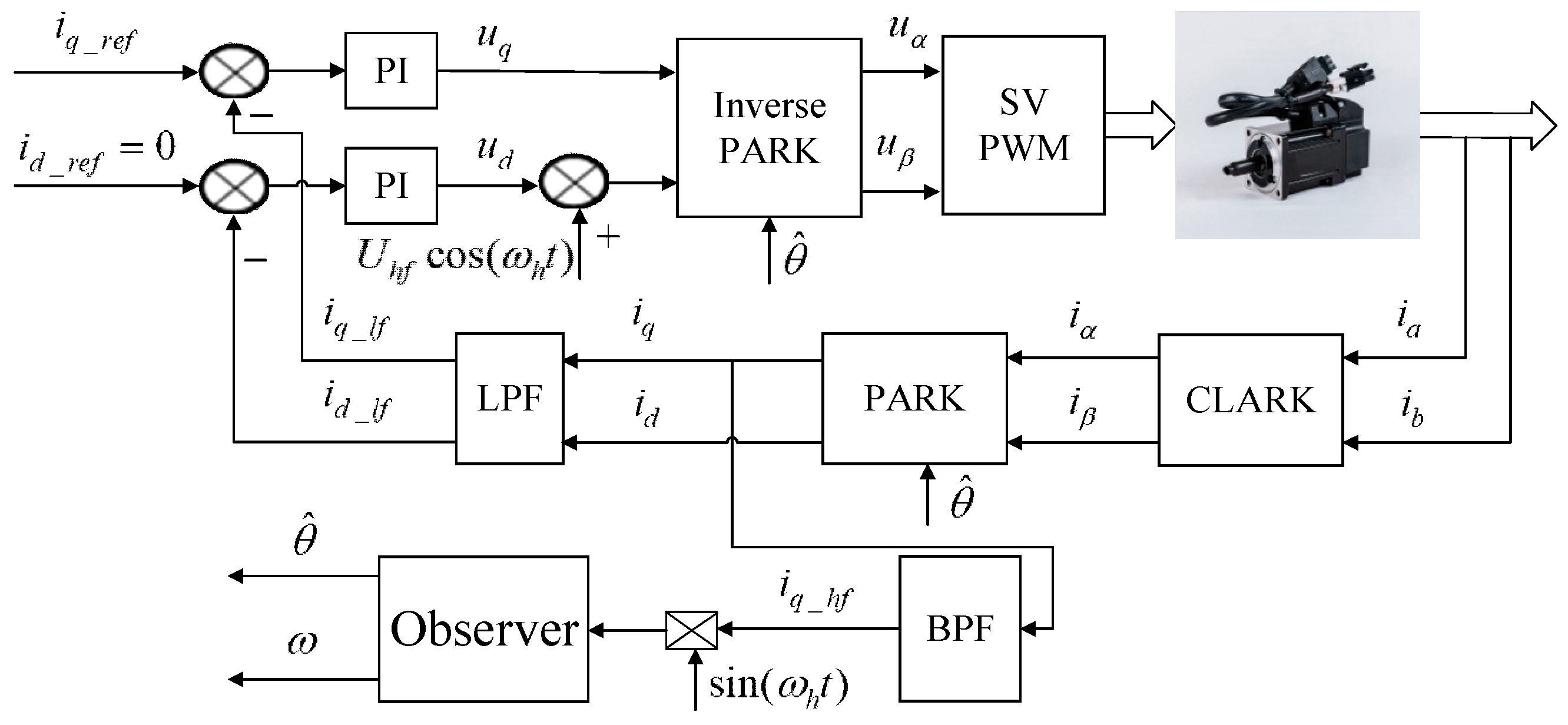
A bandpass filter (BPF) is used to extract the HF current response at the estimated q-axis. Then, by multiplying with sin ω h t , the doubling frequency component is eliminated by a lowpass filter. The remaining part for rotor position information is shown as
f ( Δ θ ) = U h Δ L 2 + L d q h 2 ω h ( L 2 Δ L 2 L d q h 2 ) sin ( 2 Δ θ θ m )
Using (6) as the input of a phase lock loop (PLL)-based position observer, the rotor position can be estimated when (6) is converged to zero at steady status. However, it is noticed that additional estimation error would occur due to the cross-coupling effect.
Δ θ = 1 2 θ m 1 2 tan 1 ( L d q h Δ L )
In the conventional pulsating high-frequency voltage injection method, the cross-coupling effect is always ignored. The error signal for position estimation is expressed as
f ( Δ θ ) = U h Δ L ω h ( L 2 Δ L 2 ) sin ( 2 Δ θ )
The control block of the conventional pulsating high-frequency voltage injection is shown in Figure 4.

2.3. Issues of the Conventional Pulsating High-Frequency Voltage Injection Method

Although pulsating high-frequency voltage injection can be used for sensorless control of the SPMSM, the sensorless capability still faces challenges for actual application:
  • The saliency ratio is small, and it decreases with the increase in load. There is no structure saliency for the SPMSM, and the saturation saliency is weak even when the HF voltage is injected. The saliency ratio may be less than 1 when the motor is operating at heavy load status.
  • The convergence region is limited and the sensorless control method even diverges in serious situations. Refs. [1,9] pointed out that it is very necessary to investigate the convergence range for the sensorless control of a PMSM, making sure the guaranteed stable sensorless performance is achieved.
  • The accuracy of position estimation is degraded due to the cross-coupling effect. Lots of research has been carried out to compensate for the estimation error due to the cross-coupling effect. However, the cross-coupling inductance is small, and it varies with the increase in load; therefore, it is a great challenge to identify the cross-coupling inductance and improve the accuracy of rotor position estimation.

3. The Proposed Sensorless Capability Expansion Method

Aiming to solve the issues above, a sensorless capability expansion method for SPMSMs is proposed based on inductance parameter identification in this section.

3.1. Inductance Parameter Identification

3.1.1. Incremental Inductance Identification

It is found that inductance information is contained in the amplitude of the HF current response when the HF voltage is injected into the motor. Therefore, it can be used for inductance parameter identification.
In this section, with the assistance of the encoder, the incremental inductances at the d-q-axis and cross-coupling inductance are identified offline in three steps by combining the rotating HF voltage injection and pulsating HF voltage injection [25,26].
Step 1: Positive and negative sequence component of HF current extraction by injecting the HF voltage at the α β -axis.
The voltage equation at α β -axis is expressed as
u α h u β h = L Δ L cos 2 θ L d q h sin 2 θ Δ L sin 2 θ + L d q h cos 2 θ Δ L sin 2 θ + L d q h cos 2 θ L + Δ L cos 2 θ + L d q h sin 2 θ p i α h i β h
when the following HF voltages are injected at the α β -axis
u α h u β h = U h cos ω h t U h sin ω h t
By substituting (10) into (9), the HF current response is shown as
i α h i β h = U h ω h ( L 2 Δ L 2 L d q h 2 ) L sin ω h t + Δ L sin ( ω h t 2 θ ) + L d q h cos ( ω h t 2 θ ) L cos ω h t + Δ L cos ( ω h t 2 θ ) L d q h sin ( ω h t 2 θ )
The vector expression of (11) is shown as
i α β h = I p e j ( ω h t π 2 ) + I n e j ( π 2 + 2 θ ω h t θ m )
where
I p = U h Σ L ω h ( Σ L 2 Δ L 2 L d q h 2 )
I n = U h Δ L 2 + L d q h 2 ω h ( Σ L 2 Δ L 2 L d q h 2 )
It can be seen that incremental inductance information is contained in the amplitude of the positive and negative sequence component of the HF current. They can be used for incremental inductance identification. However, it is not enough to identify the three incremental inductances by solving the Equations (13) and (14).
Step 2: HF current extraction by injecting the HF voltage at the actual d-axis.
The HF voltage injected at the actual d-axis is shown as
u d h u q h = U h cos ω h t 0
The current response is expressed as
i d h i q h = U h sin ω h t ω h ( L 2 Δ L 2 L d q h 2 ) L + Δ L 2 + L d q h 2 cos ( 2 Δ θ θ m ) Δ L 2 + L d q h 2 sin ( 2 Δ θ θ m )
The rotor position is obtained using the encoder, so the HF voltage is injected at the actual d-axis; therefore, Δ θ is zero. Sine and cosine values of the cross-coupling angle are calculated according to (7). Then, the amplitude of the HF current at the d-q-axis can be deduced as
I d 1 = U h ( Σ L + Δ L ) ω h ( Σ L 2 Δ L 2 L d q h 2 )
I q 1 = U h ( L d q h ) ω h ( Σ L 2 Δ L 2 L d q h 2 )
Step 3: HF current extraction by injecting the HF voltage at the actual q-axis.
The HF voltage injected at the actual q-axis is shown as
u d h u q h = 0 U h cos ω h t
The HF current response is expressed as
i d h i q h = U h sin ω h t ω h ( Σ L 2 Δ L 2 L d q h 2 ) Δ L 2 + L d q h 2 sin ( 2 Δ θ θ m ) Σ L Δ L 2 + L d q h 2 cos ( 2 Δ θ θ m )
Similar to (15) and (16), because the rotor position is obtained by the encoder, the HF voltage is injected at the actual q-axis, and the amplitude of the HF current at the d-q-axis can be deduced as
I d 2 = U h ( L d q h ) ω h ( Σ L 2 Δ L 2 L d q h 2 )
I q 2 = U h ( Σ L Δ L ) ω h ( Σ L 2 Δ L 2 L d q h 2 )
Finally, combining (13), (14), (17), (18), (21), (22), incremental inductances at the d-q-axis and cross-coupling inductance can be identified, shown as
L d i n c = 2 U h I p I q 2 ω h ( I p 2 I n 2 ) ( I d 1 + I q 2 )
L q i n c = 2 U h I p I d 1 ω h ( I p 2 I n 2 ) ( I d 1 + I q 2 )
L d q h = U h I q 1 ω h ( I p 2 I n 2 )   or   L d q h = U h I d 2 ω h ( I p 2 I n 2 )

3.1.2. Apparent Inductance Identification

Apart from incremental inductances, apparent inductances are also important parameters for identification. In this section, a sixth-order polynomial curve fitting algorithm is proposed for apparent inductance calculation based on the incremental inductance identification results.
The incremental inductance matrix considering the cross-coupling effect is a non-diagonal matrix, which includes the cross-coupling inductance. Therefore, it is necessary to transform the non-diagonal inductance matrix into a diagonal inductance matrix. Then, it will be easier to use the polynomial curve fitting algorithm for apparent inductance identification.
Using the matrix transformation, the diagonal inductance matrix can be obtained as
L d q _ a d j i n c = T ( θ m ) L d i n c L d q h L d q h L q i n c T 1 ( θ m ) = L d _ a d j i n c 0 0 L q _ a d j i n c
where L d _ a d j i n c and L q _ a d j i n c are the incremental inductances after transformation.
The matrix used for transformation is defined as
T ( θ m ) = cos θ m sin θ m sin θ m cos θ m
After transformation, the incremental inductance is a diagonal matrix, and the sixth-order polynomial curve fitting algorithm is proposed as
L d _ a d j i n c = m 6 i d 6 + m 5 i d 5 + m 4 i d 4 + m 3 i d 3 + m 2 i d 2 + m 1 i d + m 0
L q _ a d j i n c = n 6 i q 6 + n 5 i q 5 + n 4 i q 4 + n 3 i q 3 + n 2 i q 2 + n 1 i q + n 0
where m i , n i with i 0 , 1 , 2 , 3 , 4 , 5 , 6 are the polynomial coefficients.
Using the tool of “nlinfit” of MATLAB (R2021a) to solve Equations (28) and (29), the polynomial coefficients can be obtained. Then, apparent inductance can be identified as
L d a p p = L d d _ a d j i n c d i d i d = 1 7 m 5 i d 6 + 1 6 m 5 i d 5 + 1 5 m 4 i d 4 + 1 4 m 3 i d 3 + 1 3 m 2 i d 2 + 1 2 m 1 i d + m 0
L q a p p = L q q _ a d j i n c d i q i q = 1 7 n 6 i q 6 + 1 6 n 5 i q 5 + 1 5 n 4 i q 4 + 1 4 n 3 i q 3 + 1 3 n 2 i q 2 + 1 2 n 1 i q + n 0
Compared with the method in [21], the process of obtaining flux linkage through integration and division calculation are not needed. Apparent inductances at the d-q-axis are identified by the polynomial curve fitting algorithm, and the identification processes are conducted offline.

3.2. Sensorless Capability Expansion

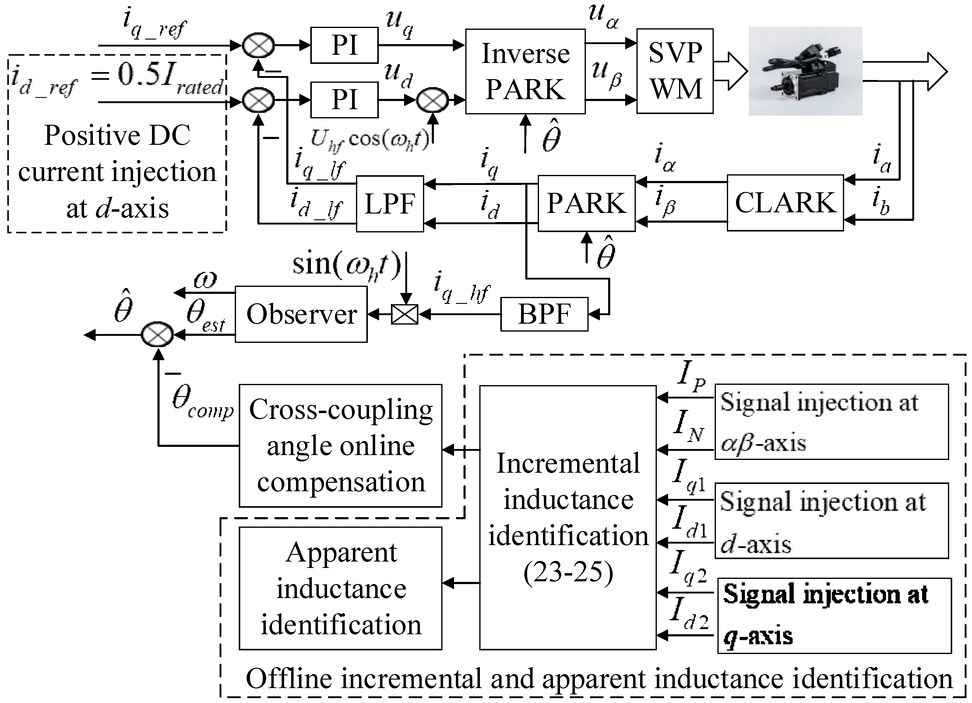
Figure 5 shows the proposed sensorless capability expansion method in this paper.
On one hand, it can be seen that the incremental inductances are identified offline by three steps combining the rotating and pulsating high-frequency voltage injection. Then, a sixth-order polynomial curve fitting algorithm is proposed for apparent inductance identification based on the incremental inductance identification results. The identification of incremental and apparent inductances is an offline method; the identification process is finished before the startup of the SPMSM. Therefore, the sensorless control of the SPMSM will not be affected by the inductance identification process.
On the other hand, according to the inductance parameter identification results, it is observed that compared with the conventional i d = 0 or i d < 0 method, the saliency ratio can be enhanced obviously when a positive DC current is injected into the d-axis. However, positive i d would generate additional copper losses; therefore, the efficiency is reduced. After balancing the saliency ratio improvement and efficiency reduction, a 50% rated current injection at the d-axis is proposed in this paper. The saliency ratio is enhanced, the convergence region is expanded, and the accuracy of position estimation is improved when the estimation error due to the cross-coupling effect is compensated for online.
θ ^ = θ e s t θ c o m p
where θ ^ is the estimated position after compensation, θ e s t is the position estimated by the observer, and θ c o m p is the compensated angle, which is equal to 0.5 θ m .

4. Experimental Verification

4.1. Experimental Platform

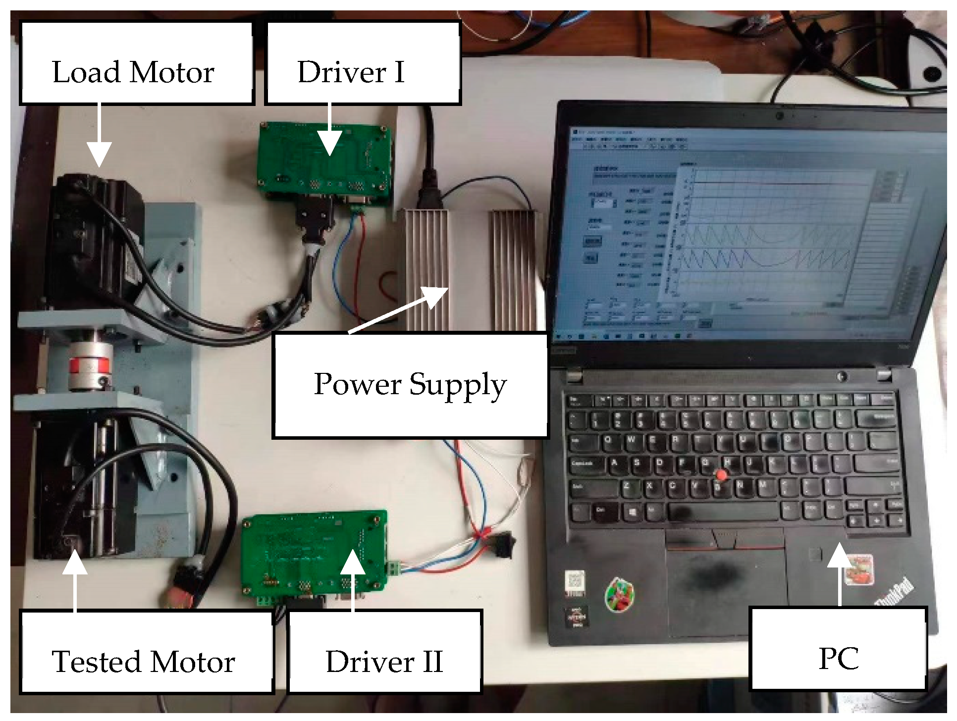
The experimental platform is shown in Figure 6. STM32F405 is selected as the MCU in the drive, the resolution of the AD converter is 12 bits, PWM switching frequency is 20 kHz and the dead time is 800 ns. During the experiment, two identical drivers are used to control the two identical SPMSMs. Among them, the tested motor operates in current control loop mode, and the load motor operates in speed control loop mode. The two drivers are connected to the power supply through a common DC bus. In order to compare the estimated rotor position accuracy, the encoder with 2500 line resolution is used to obtain the actual rotor position. The software on a PC is developed based on the VISA function of LabVIEW, and the baud rate is 500 kbit/s.
The parameters of the SPMSM used in the paper are listed in Table 1.

4.2. Inductance Parameter Identification

4.2.1. Incremental Inductance Identification

The frequency and amplitude selection of the HF voltage injected is critical for incremental inductance identification. The higher the frequency is, the greater the amplitude needed, resulting in higher HF losses. Therefore, the frequency of the voltage injected cannot be too high. At the same time, in order to reduce the non-linearity of the inverter, the amplitude of the voltage injected should be as large as possible. However, if the amplitude of the HF voltage is too large, the saturation of the magnetic field is increased, and the resolution of the incremental inductance is reduced. Therefore, the amplitude of the injected signal also needs to be selected appropriately. Finally, after comparing the parameter identification results of 100 Hz, 300 Hz, and 500 HZ, 300 Hz/26 V is selected as the frequency and amplitude of the high-frequency voltage injected for incremental inductance identification in this section.
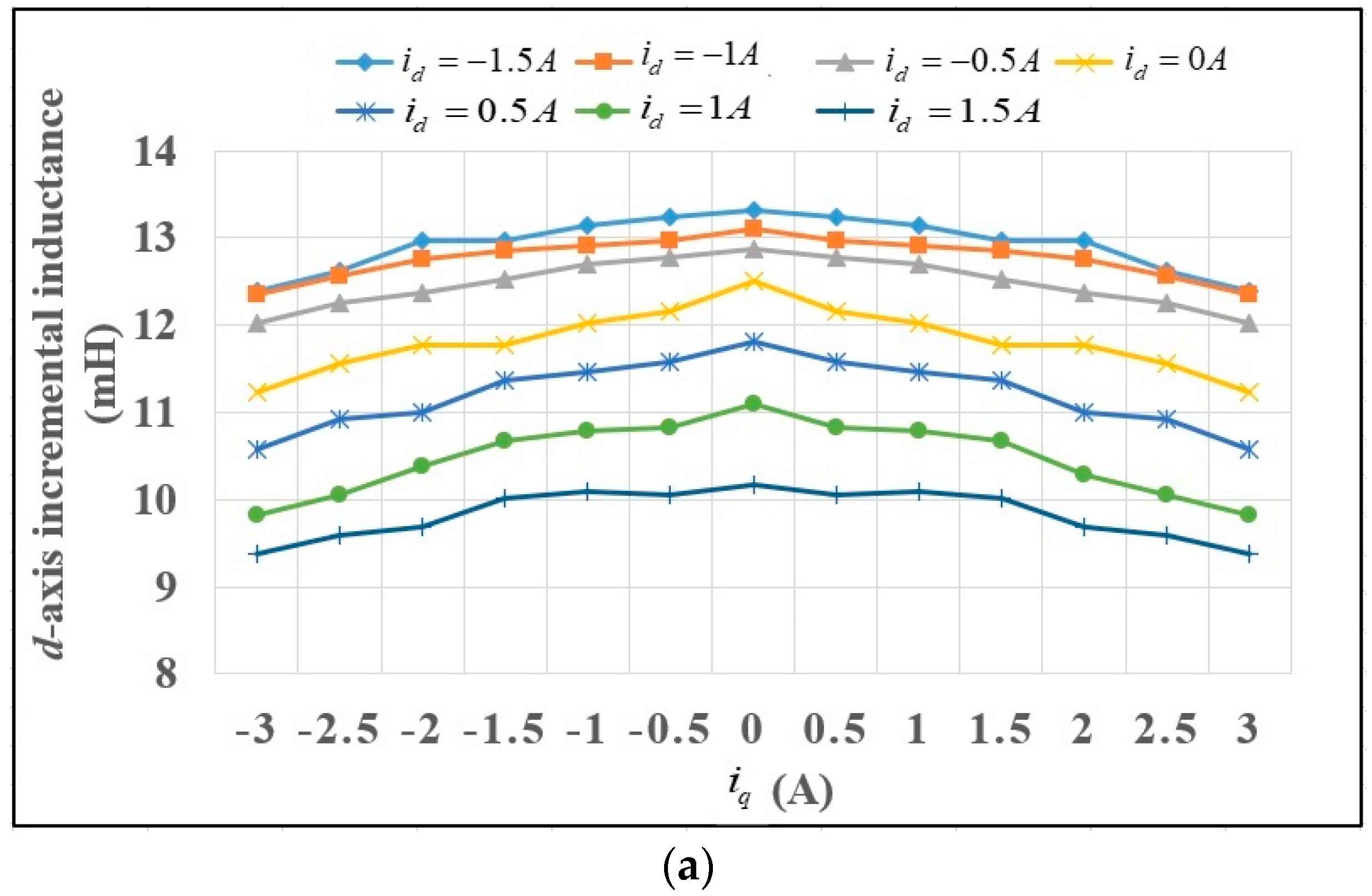
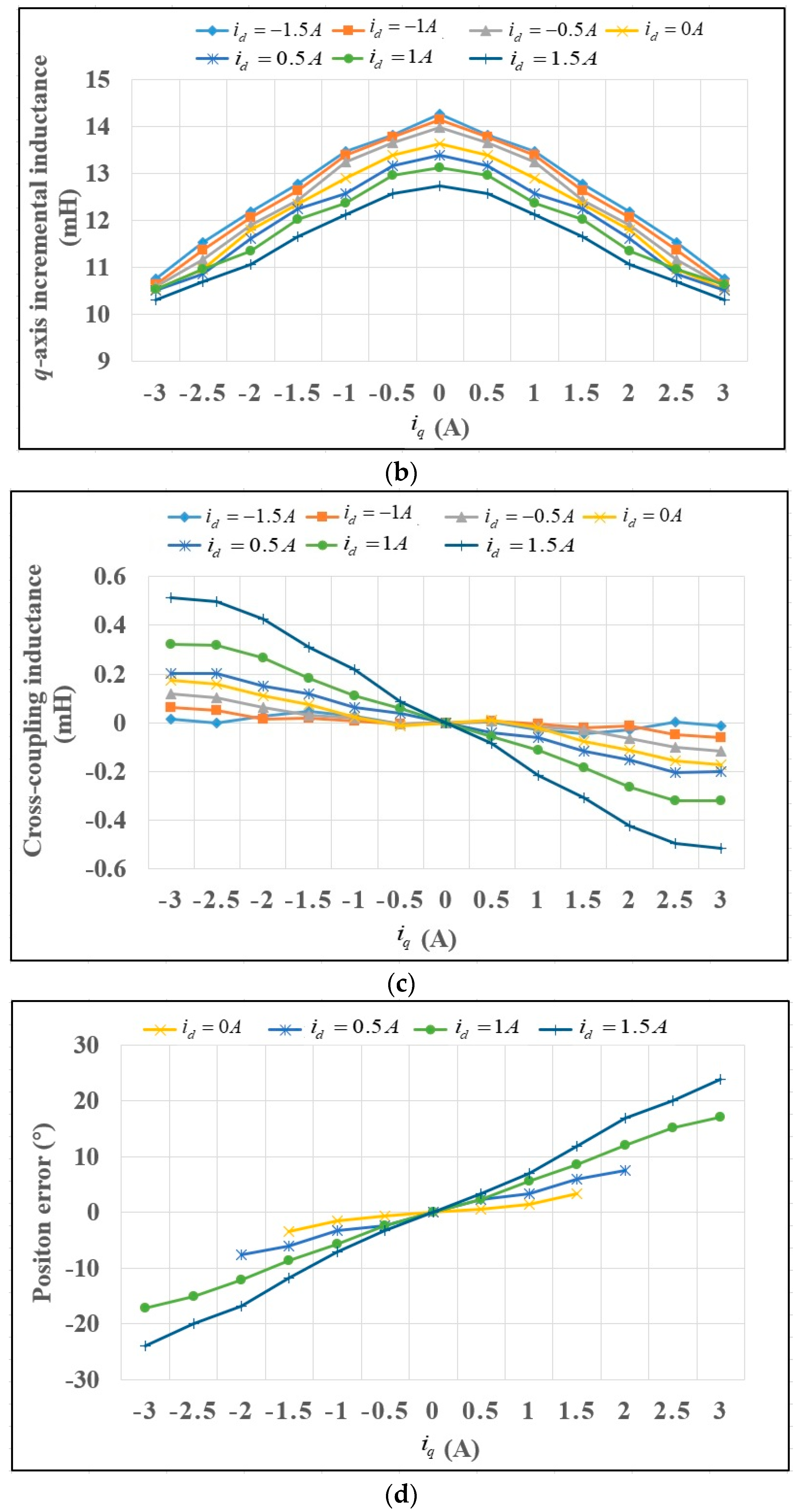
In order to know how the incremental inductances are affected by i d and i q , in the experiment, i d is set as 0 A, ±0.5 A, ±1 A and ±1.5 A; i q is set as 0 A, ±0.5 A, ±1 A, ±1.5 A, ±2 A, ±2.5 A and ±3 A, respectively. Therefore, 91 test points and seven curves are included in each figure.
Figure 7 shows the incremental inductance parameter identification results. As shown in Figure 7a,b, it can be seen that due to the saturation and cross-coupling effect, the incremental inductance of L d i n c and L q i n c gradually decreases with the increase in i q , and the variation in L q i n c is more significant than that of L d i n c . This will lead to a decrease in the saliency ratio. Figure 7c shows the identification results of L d q h . Taking the curve i d = 1.5 A as an example, it is observed that the cross-coupling inductance is −0.358 mH when i q = 1.5 A, and it reaches −0.515 mH when i q = 3 A, which is a 200% rated current. This means that the cross-coupling effect increases with the load. Figure 7d shows the calculated rotor position error due to the cross-coupling effect, which is equal to −0.5 θ m . It can be seen that the estimation error of the rotor position increases with the load; therefore, compensation is needed to improve the accuracy of position estimation, especially at heavy load status.

4.2.2. Apparent Inductance Identification

Using the tool of “nlinfit” in MATLAB, the polynomial curve fitting algorithm is proposed to identify the apparent inductances from the incremental inductances of L d _ a d j i n c , L q _ a d j i n c .
In order to evaluate the order of the polynomial on the fitting accuracy of L d _ a d j i n c and L q _ a d j i n c , the sum of squares (SOS) approximation error is calculated when the polynomials are in the order of 3, 4, 5 and 6. As shown in Figure 8, it can be seen that the approximation error decreases with the increasing polynomial order. Therefore, the sixth order is selected for the polynomial fitting of L d _ a d j i n c and L q _ a d j i n c .
Figure 9 shows the apparent inductance identification results using the six-order polynomial curve fitting algorithm. As shown in Figure 9a, the apparent inductances of L d a p p are calculated when i q = 0 . It can be seen that L d a p p is 12.97 mH when i d = 1.5 A , and L d a p p decreases to 11.45 mH when i d is increased to 1.5 A. This is because the saturation level of the magnetic field at the d-axis increases gradually with i d , which leads to the decrease in L d a p p . Meanwhile, compared with i d 0 , the variation in L d a p p is more obvious when i d > 0 , which means that the saturation level of the magnet field at the d-axis is enhanced significantly when a positive current is used for the d-axis. Figure 9b shows the identification results of L q a p p when i d = 0 . It can be seen that L q a p p is 13.625 mH when i q = 0 A , and L q a p p decreases to 12.41 mH when i q is increased to 3 A, which is a 200% rated load. This is because the saturation level of the magnetic field at the q-axis also increases gradually with i q . As a result, L q a p p decreases with the increase in i q . Compared with the method in [20,21], apparent inductance can be identified even when the fundamental current is zero using the proposed polynomial curve fitting algorithm.

4.3. Sensorless Capability Expansion

4.3.1. Saliency Ratio Improvement

Based on the incremental inductance identification results, the saliency ratio L q i n c / L d i n c at different working points is shown in Figure 10.
The following features can be observed from Figure 10:
  • The saliency ratio decreases as i q increases. This is because L q i n c is more sensitive than L d i n c to the variation of i q . The saliency ratio is less than 1 in severe cases.
  • The saliency ratio can be enhanced when a positive DC current is injected into the d-axis. Taking i q = 2 A (130% rated current) as an example, the saliency ratio is less than 1 using the conventional i d < 0 or i d = 0 method. It can be predicted that the HF voltage injection method would fail at these working points. On the contrary, the saliency ratio gradually increases with the positive value of i d , and the saliency ratio reaches 1.13 when i d = 1.5 A .
According to the analysis above, it can be predicted that using the proposed method, when a 50% rated current is injected at the d-axis, the saliency ratio would be enhanced compared with the conventional i d = 0 or i d < 0 method.

4.3.2. Convergence Region Expansion

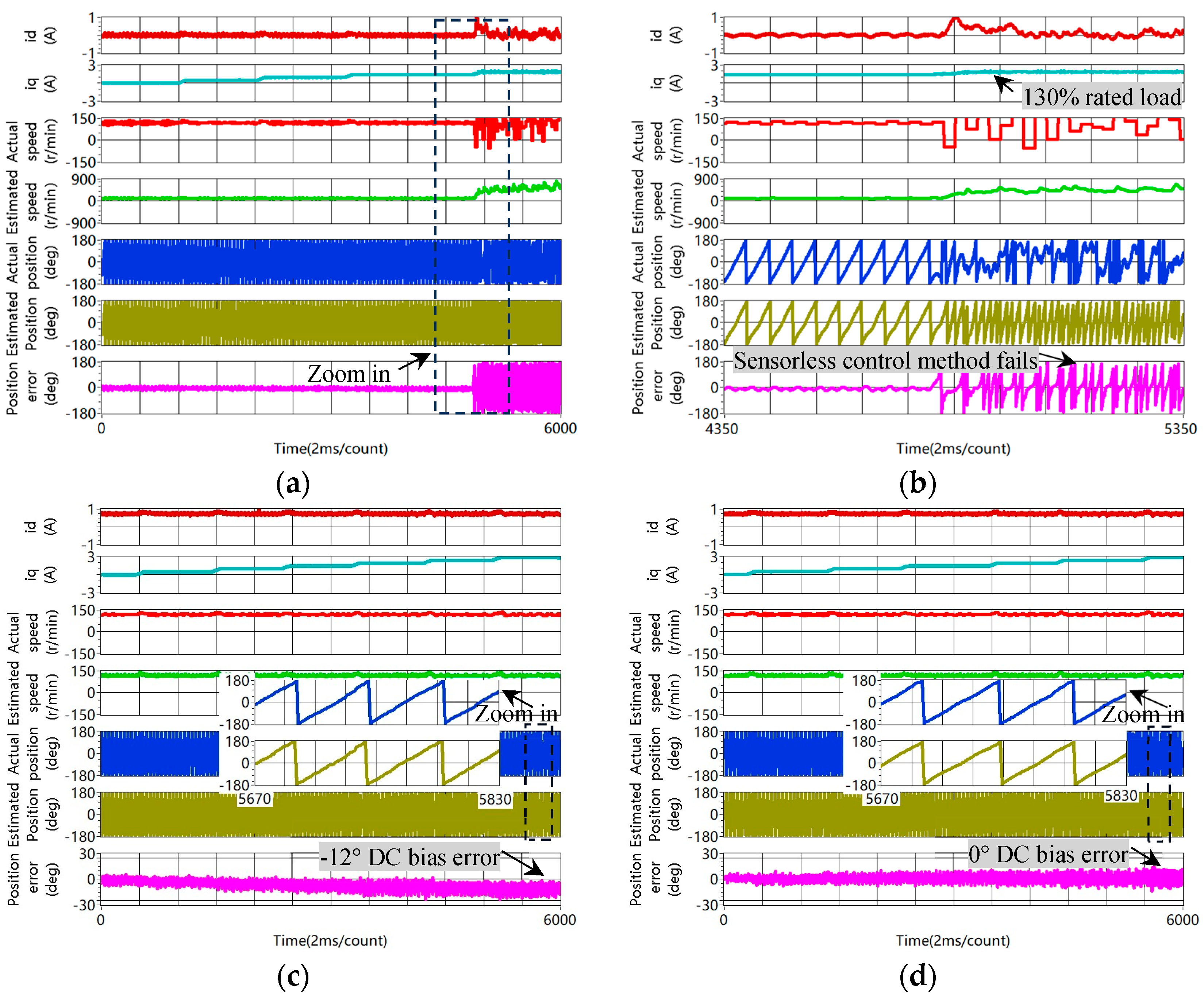
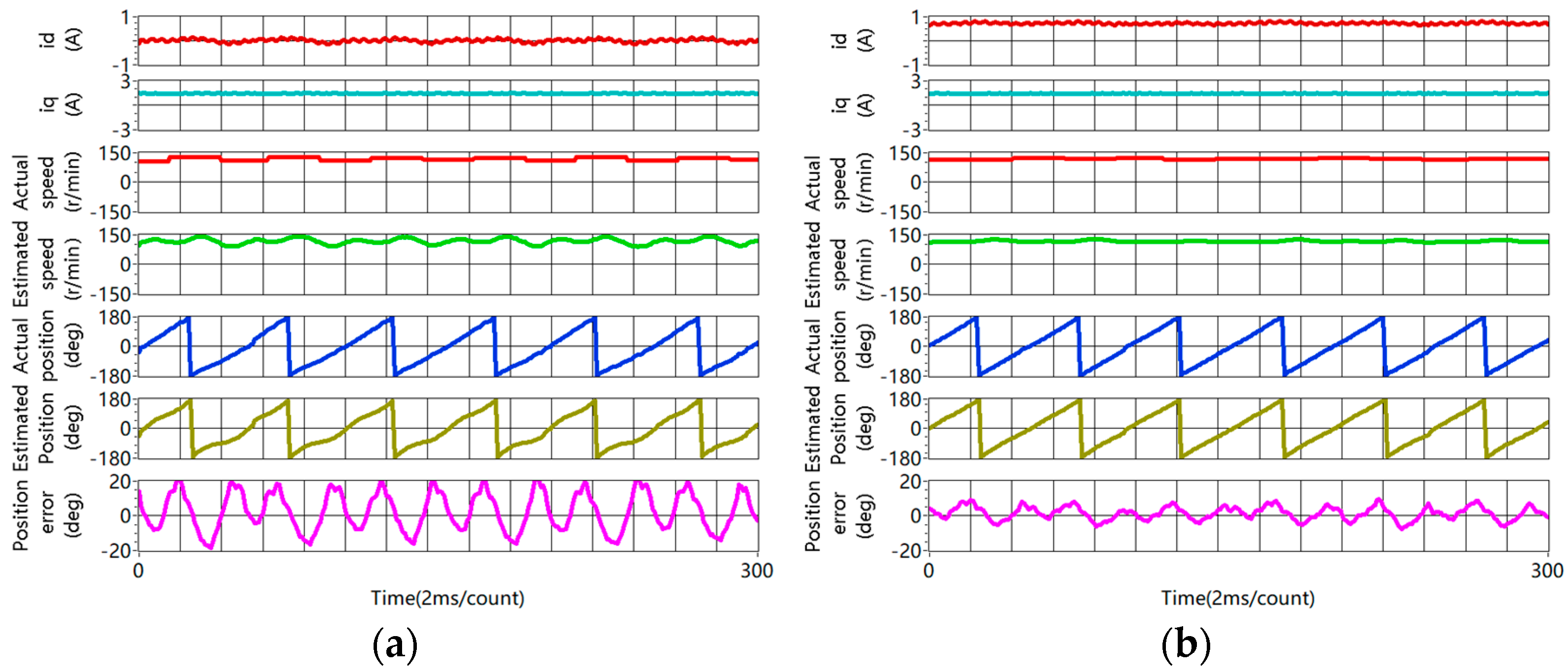
Figure 11 compares the convergence range between the conventional method and the proposed method when the motor is operating at 120 r/min. In each figure, i d , i q , actual rotor speed, estimated rotor speed, actual rotor position, estimated rotor position and position error are listed from top to bottom.
As shown in Figure 11a, using the conventional method, the sensorless control based on pulsating high-frequency voltage diverges at a 130% rated load. This is because the saliency ratio is less 1 at this working point. This experimental result is consistent with the analysis of Figure 7. With the help of zooming in, as shown in Figure 11b, the position error is fluctuating at ±180, which means that the rotor position estimation fails at this situation and the convergence range of the sensorless control method is limited at heavy load status. On the contrary, as shown in Figure 11c, using the proposed method, it is observed that the sensorless control method works well at a 130% rated load; furthermore, the convergence range is even expanded to a 200% rated load. It is also observed that the estimated rotor position gradually deviates from the actual rotor position due to the crossing coupling effect, and a nearly 12° DC bias error occurs at a 200% rated load. In Figure 11d, using the online compensation method, the DC bias error is eliminated, and the rotor position error stays around at 0° regardless of the increase in the load. Figure 11 verifies that the convergence region of the sensorlsess control is expanded to a 200% rated load using the proposed method.

4.3.3. Accuracy of Rotor Position Estimation Improvement

In order to verify how the accuracy of rotor position estimation is improved using the proposed method, the following experiments are carried out.
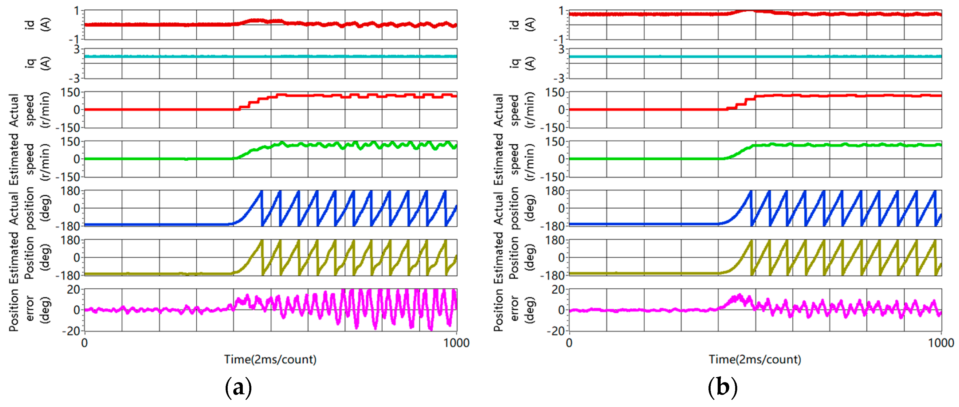
Figure 12 shows a comparison of the startup performance between the conventional method and the proposed method with a rated load. As shown in Figure 12a, it can be seen that the motor can start from 0 to 120 r/min using the conventional method; however, the position error increases with rotor speed, and the maximum error exceeds 20° at steady status. On the contrary, using the proposed method in Figure 12b, the position error is ±10° during the startup process. Meanwhile, the speed estimation is smoother. This proves that the startup performance is better using the proposed method.
Figure 13 shows the experimental results of rotor position estimation when the motor is operating at 120 r/min with a rated load. As shown in Figure 13a, using the conventional i d = 0 method, the position estimation error is ±20°. However, as shown in Figure 13b, using the proposed method, the estimation error keeps within ±10° at steady status. This proves that the accuracy of rotor position estimation is obviously improved using the proposed method.
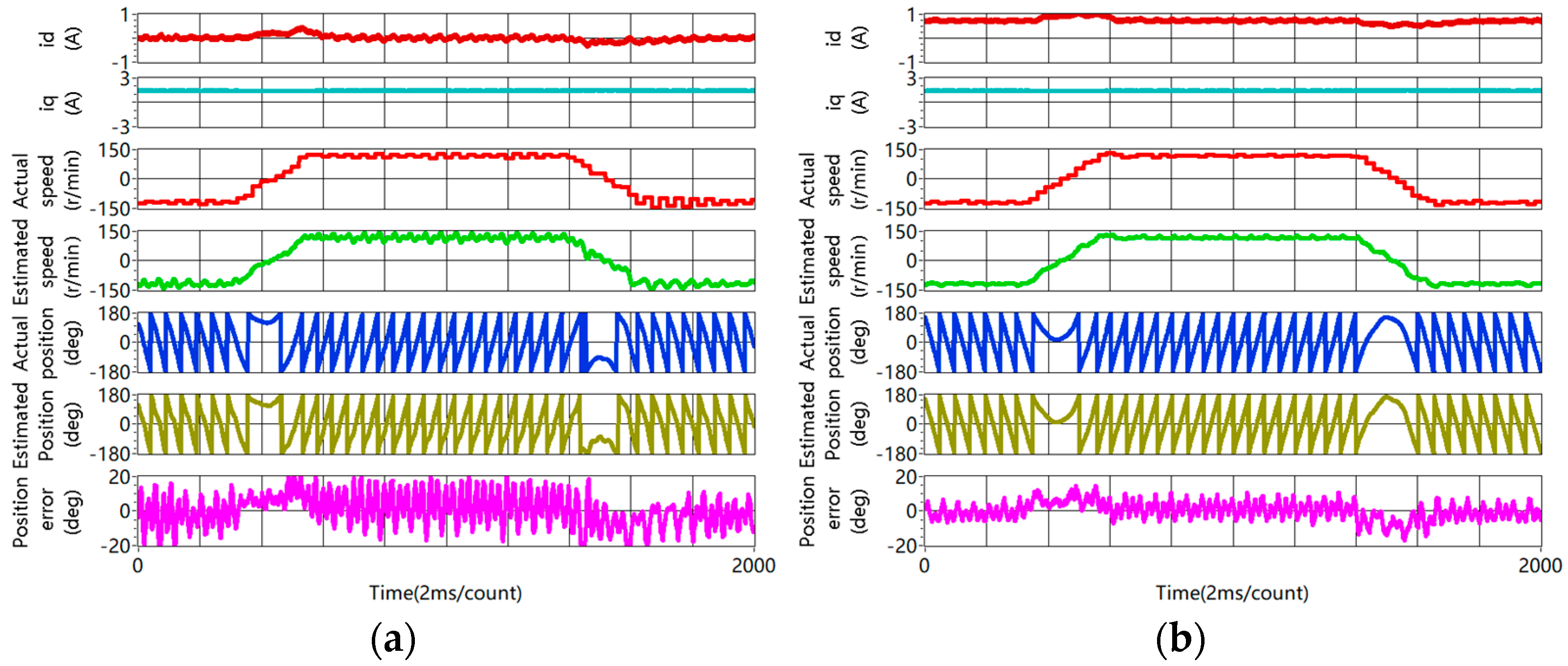
Figure 14 shows the experimental result during the dynamic process that the speed is changed from −120 r/min to 120 r/min, then back to −120 r/min at the rated load. As shown in Figure 14a, using the conventional i d = 0 method, during the dynamic process in which the speed is changed from −120 r/min to 120 r/min, the estimated position error exceeds 20°. When the rotor speed is changed from 120 r/min to −120 r/min, the estimated position error exceeds −20°. On the contrary, as shown in Figure 14b, using the proposed method, the estimation error keeps within ±15° during the speed reversal process. The experimental results prove that the accuracy of rotor position estimation is enhanced using the proposed method during the speed reversal test.
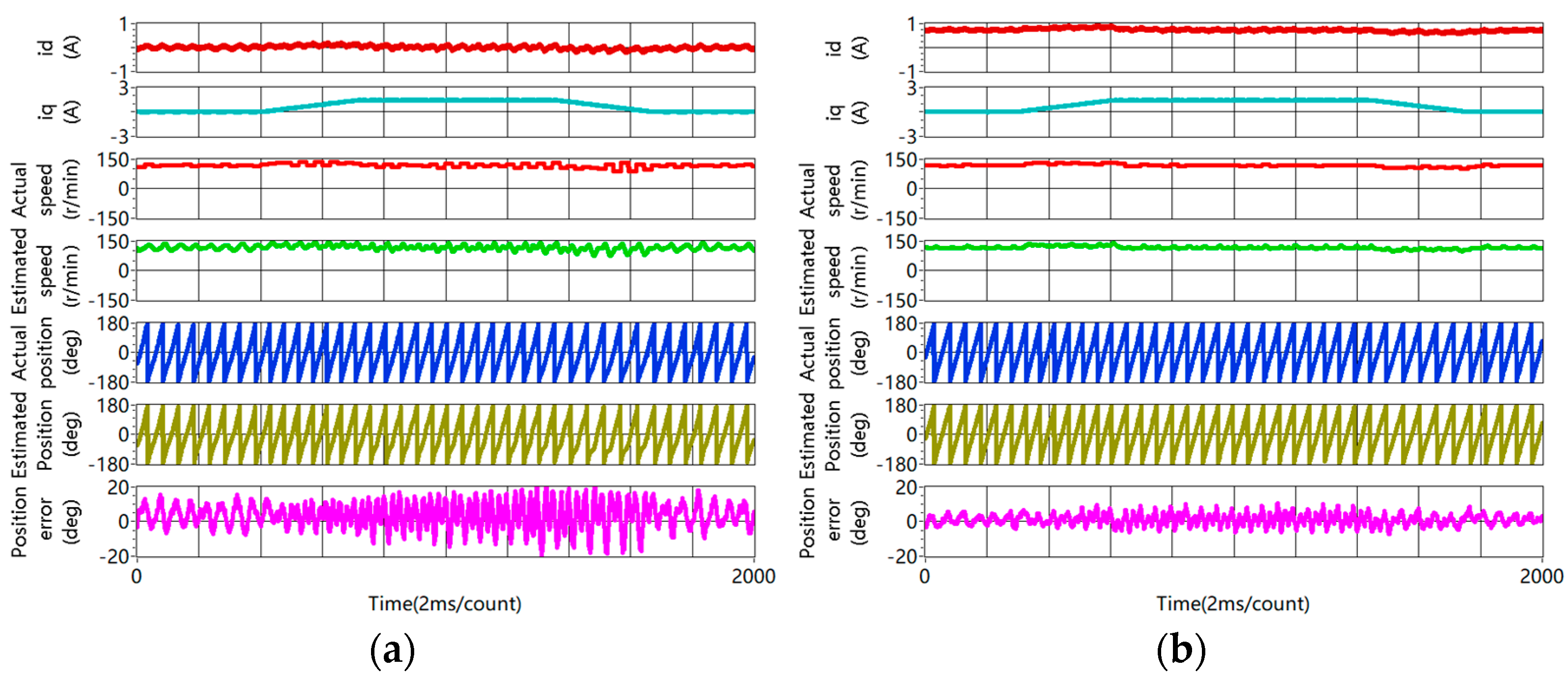
Figure 15 shows the experimental results of rotor position estimation during the loading and unloading process. As shown in Figure 15a, using the conventional i d = 0 method, the rotor position estimation error increases with i q during the loading process, and the fluctuation error is greater than ±20° at a 100% rated load. When the load is decreased to 0, the estimation error is ±15°. Meanwhile, obvious fluctuation error is observed for the rotor speed estimation. On the contrary, as shown in Figure 15b, using the proposed method, the position estimation error keeps within ±10° during the dynamic loading and unloading process. When the load is decreased to 0, the estimation error is less than ±5°. The speed estimation is smoother than the conventional method. Therefore, this validates that the accuracy of rotor position estimation is better using the proposed method during the loading and unloading process.
Figure 16 shows the rotor position estimation when the motor is operating at 120 r/min with a 200% rated load. As shown in Figure 16a, due to the effect of cross-coupling, an almost −12° DC bias error occurred at the 200% rated load, and the position estimation error exceeds −25°. On the contrary, as shown in Figure 16b, using the online compensation method based on the parameter identification in Figure 7d, the DC bias error is eliminated, the position estimation stays around at 0°, and the fluctuation error is within ±15°. The experimental data verify that the accuracy of position estimation is improved at a 200% rated load.

5. Conclusions

This article proposes a sensorless capability expansion method for an SPMSM based on inductance parameter identification. The contributions of this article are as follows:
  • Incremental inductances are identified offline in three steps combining the rotating high-frequency voltage injection and pulsating high-frequency voltage injection. Then, a polynomial curve fitting algorithm is proposed for apparent inductance identification.
  • The saliency ratio is enhanced by injecting a positive DC current into the d-axis. Compared with the conventional i d = 0 or i d < 0 method, the saturation level at the d-axis is enhanced and the saliency ratio is improved obviously.
  • The convergence region of the pulsating high–frequency voltage injection method is expanded at heavy load status. Using the conventional method, the sensorless control method fails at a 120% rated current. On the contrary, using the proposed method, the rotor position estimation works well at a 200% rated current.
  • The experimental results show that the accuracy of rotor position estimation is improved obviously at the steady state and during the dynamic process.
The sensorless capability of the SPMSM is improved obviously using the proposed positive DC current injection at the estimated d-axis. However, it is noticed that the energy losses and resulting heat dissipation are increased at the same time. Therefore, there would be a tradeoff between the sensorless capability expansion and the energy losses. Meanwhile, half of the nominal current at the d-axis in this paper is not mandatory, and the positive value of i d needs to be optimized according to the overload level. Future research work will focus on the trajectory planning of i d . The target is to achieve a balance between the sensorless capability expansion for the SPMSM and the energy losses.

Author Contributions

Conceptualization, P.C., R.M. and S.S.; funding acquisition, R.M., Z.C. and S.S.; methodology, Z.C.; software, P.C.; validation, Z.C.; formal analysis, P.C.; investigation, P.C. and Z.C.; writing—original draft preparation, P.C. and R.M.; writing—review and editing, P.C., Z.C. and S.S.; visualization, Z.C. and S.S. All authors have read and agreed to the published version of the manuscript.

Funding

This work is supported in part by the National Natural Science Foundation of China under Grant 52177059 and in part by the Shaanxi Provincial Science Foundation for Distinguished Young Scholars under Grant 2023-JC-JQ-44.

Data Availability Statement

The data presented in this study are available from the corresponding authors upon reasonable request. Data available on request due to privacy.

Conflicts of Interest

The authors declare no conflicts of interest.

References

  1. Berto, M.; Alberti, L.; Manzolini, V.; Bolognani, S. Computation of Self-Sensing Capabilities of Synchronous Machines for Rotating High Frequency Voltage Injection Sensorless Control. IEEE Trans. Ind. Electron. 2022, 69, 3324–3333. [Google Scholar] [CrossRef]
  2. Lee, Y.; Sul, S.-K. Model-Based Sensorless Control of an IPMSM with Enhanced Robustness Against Load Disturbances Based on Position and Speed Estimator Using a Speed Error. IEEE Trans. Ind. Appl. 2018, 54, 1448–1459. [Google Scholar] [CrossRef]
  3. Naderian, M.; Markadeh, G.A.; Karimi-Ghartemani, M.; Mojiri, M. Improved Sensorless Control Strategy for IPMSM Using an ePLL Approach With High-Frequency Injection. IEEE Trans. Ind. Electron. 2024, 71, 2231–2241. [Google Scholar] [CrossRef]
  4. Ortombina, L.; Berto, M.; Alberti, L. Sensorless Drive for Salient Synchronous Motors Based on Direct Fitting of Elliptical-Shape High-Frequency Currents. IEEE Trans. Ind. Electron. 2023, 70, 3394–3403. [Google Scholar] [CrossRef]
  5. Zhang, Y.; Yin, Z.; Liu, J.; Zhang, R.; Sun, X. IPMSM Sensorless Control Using High-Frequency Voltage Injection Method with Random Switching Frequency for Audible Noise Improvement. IEEE Trans. Ind. Electron. 2020, 67, 6019–6030. [Google Scholar] [CrossRef]
  6. Jang, J.-H.; Sul, S.-K.; Ha, J.-I.; Ide, K.; Sawamura, M. Sensorless drive of surface-mounted permanent-magnet motor by high-frequency signal injection based on magnetic saliency. IEEE Trans. Ind. Appl. 2003, 39, 1031–1039. [Google Scholar] [CrossRef]
  7. Berto, M.; Alberti, L.; Bolognani, S. Measurement of the Self-Sensing Capability of Synchronous Machines for High Frequency Signal Injection Sensorless Drives. IEEE Trans. Ind. Appl. 2023, 59, 3381–3389. [Google Scholar] [CrossRef]
  8. Manzolini, V.; Bolognani, S. On the Rotor Position Self-Sensing Capability of Reluctance and IPM Synchronous Motors. IEEE Trans. Ind. Appl. 2020, 56, 3755–3766. [Google Scholar] [CrossRef]
  9. Frenzke, T. Impacts of cross-saturation on sensorless control of surface permanent magnet synchronous motors. In Proceeding of the 2005 European Conference on Power Electronics and Applications, Dresden, Germany, 11–14 September 2005. [Google Scholar]
  10. Lin, T.C.; Zhu, Z.Q. Sensorless Operation Capability of Surface-Mounted Permanent-Magnet Machine Based on High-Frequency Signal Injection Methods. IEEE Trans. Ind. Appl. 2015, 51, 2161–2171. [Google Scholar] [CrossRef]
  11. Kano, Y.; Matsui, N. Rotor Geometry Design of Saliency-Based Sensorless Controlled Distributed-Winding IPMSM for Hybrid Electric Vehicles. IEEE Trans. Ind. Appl. 2018, 54, 2336–2348. [Google Scholar] [CrossRef]
  12. Millinger, J.; Bacco, G.; Manzolini, V.; Wallmark, O.; Bianchi, N. Design and Evaluation of a Short-Circuit Rotor-Ring for Enhanced Self-Sensing Capability in a Slotless PM Motor. IEEE Trans. Ind. Electron. 2020, 67, 3462–3471. [Google Scholar] [CrossRef]
  13. Ponomarev, P.; Petrov, I.; Pyrhönen, J. Influence of Travelling Current Linkage Harmonics on Inductance Variation, Torque Ripple and Sensorless Capability of Tooth-Coil Permanent-Magnet Synchronous Machines. IEEE Trans. Magn. 2014, 50, 1–8. [Google Scholar] [CrossRef]
  14. Kwon, Y.-C.; Lee, J.; Sul, S.-K. Extending Operational Limit of IPMSM in Signal-Injection Sensorless Control by Manipulation of Convergence Point. IEEE Trans. Ind. Appl. 2019, 55, 1574–1586. [Google Scholar] [CrossRef]
  15. Lee, J.; Kwon, Y.-C.; Sul, S.-K. Signal-Injection Sensorless Control with Tilted Current Reference for Heavily Saturated IPMSMs. IEEE Trans. Power Electron. 2020, 35, 12100–12109. [Google Scholar] [CrossRef]
  16. Wang, H.; Lu, K.; Wang, D.; Blaabjerg, F. Simple and Effective Online Position Error Compensation Method for Sensorless SPMSM Drives. IEEE Trans. Ind. Appl. 2020, 56, 1475–1484. [Google Scholar] [CrossRef]
  17. Rafaq, M.S.; Jung, J.-W. A Comprehensive Review of State-of-the-Art Parameter Estimation Techniques for Permanent Magnet Synchronous Motors in Wide Speed Range. IEEE Trans. Ind. Electron. 2020, 16, 4747–4758. [Google Scholar] [CrossRef]
  18. Ceylan, D.; Friedrich, L.A.J.; Boynov, K.O.; Lomonova, E.A. Effects of DC-Field Excitation on the Incremental Inductance of a Variable Flux Reluctance Machine. IEEE Trans. Magn. 2021, 57, 1–5. [Google Scholar] [CrossRef]
  19. Chen, J.; Li, J.; Qu, R.; Ge, M. Magnet-Frozen-Permeability FEA and DC-Biased Measurement for Machine Inductance: Application on a Variable-Flux PM Machine. IEEE Trans. Ind. Electron. 2018, 65, 4599–4607. [Google Scholar] [CrossRef]
  20. Pellegrino, G.; Boazzo, B.; Jahns, T.M. Magnetic Model Self-Identification for PM Synchronous Machine Drives. IEEE Trans. Ind. Appl. 2015, 51, 2246–2254. [Google Scholar] [CrossRef]
  21. Stumberger, B.; Stumberger, G.; Dolinar, D.; Hamler, A.; Trlep, M. Evaluation of saturation and cross-magnetization effects in interior permanent-magnet synchronous motor. IEEE Trans. Ind. Appl. 2003, 39, 1264–1271. [Google Scholar] [CrossRef]
  22. Wu, C.; Zhao, Y.; Sun, M. Enhancing Low-Speed Sensorless Control of PMSM Using Phase Voltage Measurements and Online Multiple Parameter Identification. IEEE Trans. Power Electron. 2020, 35, 10700–10710. [Google Scholar] [CrossRef]
  23. Wang, Q.; Zhao, N.; Wang, G.; Zhao, S.; Chen, Z.; Zhang, G.; Xu, D. An Offline Parameter Self-Learning Method Considering Inverter Nonlinearity With Zero-Axis Voltage. IEEE Trans. Power Electron. 2021, 36, 14098–14109. [Google Scholar] [CrossRef]
  24. Xu, W.; Lorenz, R.D. High-Frequency Injection-Based Stator Flux Linkage and Torque Estimation for DB-DTFC Implementation on IPMSMs Considering Cross-Saturation Effects. IEEE Trans. Ind. Appl. 2014, 50, 3805–3815. [Google Scholar] [CrossRef]
  25. Shuang, B.; Zhu, Z.-Q. A Novel Method for Estimating the High Frequency Incremental DQ-Axis and Cross-Coupling Inductances in Interior Permanent Magnet Synchronous Machines. IEEE Trans. Ind. Appl. 2021, 57, 4913–4923. [Google Scholar] [CrossRef]
  26. Shuang, B.; Zhu, Z.Q.; Wu, X. Improved Cross-coupling Effect Compensation Method for Sensorless Control of IPMSM with High Frequency Voltage Injection. IEEE Trans. Energy Convers. 2022, 37, 347–358. [Google Scholar] [CrossRef]
  27. Huang, Z.; Lin, C.; Xing, J. A Parameter-Independent Optimal Field-Weakening Control Strategy of IPMSM for Electric Vehicles Over Full Speed Range. IEEE Trans. Power Electron. 2021, 36, 4659–4671. [Google Scholar] [CrossRef]
  28. Ryu, J.-Y.; Hwang, S.-W.; Chin, J.-W.; Hwang, Y.-S.; Yoon, S.W.; Lim, M.-S. Mathematical Modeling of Fast and Accurate Coupled Electromagnetic-Thermal Analysis. IEEE Trans. Ind. Appl. 2021, 57, 4636–4645. [Google Scholar] [CrossRef]
  29. Aggarwal, A.; Allafi, I.M.; Strangas, E.G.; Agapiou, J.S. Off-Line Detection of Static Eccentricity of PMSM Robust to Machine Operating Temperature and Rotor Position Misalignment Using Incremental Inductance Approach. IEEE Trans. Transp. Electrif. 2021, 7, 161–169. [Google Scholar] [CrossRef]
  30. Liu, Z.; Fan, X.; Kong, W.; Cao, L.; Qu, R. Improved Small-Signal Injection-Based Online Multiparameter Identification Method for IPM Machines Considering Cross-Coupling Magnetic Saturation. IEEE Trans. Power Electron. 2022, 37, 14362–14374. [Google Scholar] [CrossRef]
  31. Seilmeier, M.; Piepenbreier, B. Identification of steady-state inductances of PMSM using polynomial representations of the flux surfaces. In Proceeding of the IECON 2013–39th Annual Conference of the IEEE Industrial Electronics Society, Vienna, Austria, 10–13 November 2013. [Google Scholar]
  32. Feng, G.; Lai, C.; Han, Y.; Kar, N.C. Fast Maximum Torque Per Ampere (MTPA) Angle Detection for Interior PMSMs Using Online Polynomial Curve Fitting. IEEE Trans. Power Electron. 2022, 37, 2045–2056. [Google Scholar] [CrossRef]
Figure 1. Incremental inductance and apparent inductance.
Energies 17 03219 g001
Figure 2. Equivalent circuit on the d-q-axis: (a) d-axis; (b) q-axis.
Energies 17 03219 g002
Figure 3. Reference frame and rotor position estimation.
Energies 17 03219 g003
Figure 4. Conventional pulsating high-frequency voltage injection method.
Energies 17 03219 g004
Figure 5. The proposed sensorless capability expansion method for SPMSM.
Energies 17 03219 g005
Figure 6. Experiment platform.
Energies 17 03219 g006
Figure 7. Incremental inductance identification: (a) L d i n c ; (b) L q i n c ; (c) L d q h ; (d) − 0.5 θ m .
Energies 17 03219 g007aEnergies 17 03219 g007b
Figure 8. Sum of squares (SOS) approximation error as the function of the polynomial order m for L d _ a d j i n c and order n for L q _ a d j i n c : (a) L d _ a d j i n c ; (b) L q _ a d j i n c .
Energies 17 03219 g008
Figure 9. Apparent inductance identification result: (a) L d a p p ; (b) L q a p p .
Energies 17 03219 g009
Figure 10. Saliency ratio variation with i d and i q .
Energies 17 03219 g010
Figure 11. Experimental results of convergence range comparison at 120 r/min: (a) conventional method; (b) zoom in of the conventional method in which sensorless control of the SPMSM fails when the load is increased to a 130% rated value; (c) proposed method without compensation for the position estimation error due to the cross-coupling effect; (d) proposed method with compensation for the position estimation error due to the cross-coupling effect.
Energies 17 03219 g011
Figure 12. Comparison of rotor position estimation during starting process (from 0 to 120 r/min with rated load): (a) conventional method; (b) proposed method.
Energies 17 03219 g012
Figure 13. Rotor position estimation at 120 r/min with rated load: (a) conventional method; (b) proposed method.
Energies 17 03219 g013
Figure 14. Rotor position estimation during the dynamic process of speed reversal test with rated load (rotor speed changes from −120 r/min to 120 r/min, then back to −120 r/min): (a) conventional method; (b) proposed method.
Energies 17 03219 g014
Figure 15. Rotor position estimation during the loading and unloading process at 120 r/min (load increases from 0 to rated value, then back to 0): (a) conventional method; (b) proposed method.
Energies 17 03219 g015
Figure 16. Rotor position estimation at 120 r/min with a 200% rated load: (a) without compensation for the error due to cross-coupling effect; (b) with compensation for the error due to cross-coupling effect.
Energies 17 03219 g016
Table 1. Parameters of the test motor.
ItemValueItemValue
Rated voltage110 VPole pairs5
Rated current1.5 APhase resistance2.8 Ω
Rated power200 Wd-axis inductance13 mH
Rated torque0.64 Nmq-axis inductance13 mH
Disclaimer/Publisher’s Note: The statements, opinions and data contained in all publications are solely those of the individual author(s) and contributor(s) and not of MDPI and/or the editor(s). MDPI and/or the editor(s) disclaim responsibility for any injury to people or property resulting from any ideas, methods, instructions or products referred to in the content.