Article

Intelligent Integration of Vehicle-to-Grid (V2G) and Vehicle-for-Grid (V4G) Systems: Leveraging Artificial Neural Networks (ANNs) for Smart Grid

1
Research Laboratory of Physics and Engineers Sciences (LRPSI), Research Team in Embedded Systems, Engineering, Automation, Signal, Telecommunications and Intelligent Materials (ISASTM), Polydisciplinary Faculty (FPBM), Sultan Moulay Slimane University (USMS), Beni Mellal 23040, Morocco
2
Multidisciplinary Laboratory of Research and Innovation (LPRI), Moroccan School of Engineering Sciences (EMSI), Casablanca 20250, Morocco
*
Author to whom correspondence should be addressed.
Energies 2024, 17(13), 3095; https://doi.org/10.3390/en17133095
Submission received: 28 May 2024 / Revised: 10 June 2024 / Accepted: 18 June 2024 / Published: 23 June 2024
(This article belongs to the Section F3: Power Electronics)

Abstract

:
This paper presents a groundbreaking control strategy for a bidirectional battery charger that allows power to be injected into the smart grid while simultaneously compensating for the grid’s reactive power using an electric vehicle battery. An artificial neural network (ANN) controller is utilized for precise design to ensure optimal performance with minimal error. The ANN technique is applied to generate sinusoidal pulse width modulation (SPWM) for a bidirectional AC–DC inverter, with the entire algorithm simulated in MATLAB Simulink.The core innovation of this study is the creation of the ANN algorithm, which supports grid compensation using electric vehicle batteries, an approach termed “vehicle-for-grid”. Additionally, the paper details the PCB circuit design of the system controlled by the DSP F28379D board, which was tested on a three-phase motor. The total harmonic distortion (THD) of the proposed ANN algorithm is approximately 1.85 % , compared to the MPC algorithm’s THD of about 2.85 % . This indicates that the proposed algorithm is more effective in terms of the quality of the power injected into the grid. Furthermore, it demonstrates effective grid compensation, with the reactive power effectively neutralized to 0 KVAR in the vehicle-for-grid mode.

1. Introduction

Grid-connected inverters play a vital role in renewable energy systems, making them ideal for integration with the electrical grid. These inverters employ sophisticated control algorithms to meet grid requirements [1]. Additionally, the integration of electric vehicles (EVs) into vehicle-to-grid (V2G) systems offers a valuable opportunity to enhance the profitability of multi-energy microgrid operators (MMOs) [2]. As the worldwide shift toward sustainable energy gains momentum, the inclusion of electric vehicles (EVs), energy storage, and renewable energy sources is becoming a central strategy [3]. Another advantage that EV manufacturers and supporters are promoting is the promise of vehicle-to-grid (V2G) charging, which enables an EV’s battery to send power to utilities. V2G charging provides benefits for EV owners as well as fortifying the electric grid and providing financial incentives. Due to the rising pollution and carbon dioxide emissions from the burning of fossil fuels, as well as rising energy demands, electric automobiles have gained popularity during the past 20 years [4]. EVs provide a substitute for using fewer fossil fuels. Numerous research trials have been conducted; however, EVs have not yet demonstrated useful effects that are palatable [4,5]. The battery and the way it is charged are essential parts of EVs [6]. In the literature, a number of charging topology classifications are provided [7,8]. Starting out, there are two charging options to choose from: offboard and onboard [9]. Bidirectional onboard converters are necessary for EVs to operate in the V2X mode [10,11]. This way of operation is used to provide the utility or system a number of advantages. A significant amount of research is being conducted globally due to the numerous advantages the V2X technology offers. The main goal of this research is to create effective converter topologies with high power densities and control methods to enhance the intelligence of V2X systems. V2X functionality research is still in its early stages [12]. The power density, power level, converter topologies, and control methods connected to the V2X system all require extensive study. As a result, V2X systems have not been heavily advertised [13,14]. The majority of the reported effort during the previous ten years focuses on the creation of rapid chargers [15]. Future study regarding the V2X system offers a wide range of potential applications. Electric vehicles, smart houses, smart loads, and the main grid are all powered by the V2X system, allowing it to operate in a variety of ways. However, the discussion in this work is restricted to the modes of vehicle-to-grid (V2G), vehicle-for-grid (V4G), vehicle-to-vehicle (V2V), vehicle-to-home (V2H), and vehicle-to-load (V2L). All those operations are shown in Figure 1. The study being conducted now focuses on the mature development of these modes of operation [11,16]. The V2G capability of the V2X system is the most crucial of these modes of operation. The V2G capability is utilized to deliver a variety of services, including the regulation of the active power demand, the reactive power compensation, the compensation of the harmonics in the grid current, and the enhancement of system dependability, stability, and efficiency [17]. This is in addition to improving the reliability of the supply.
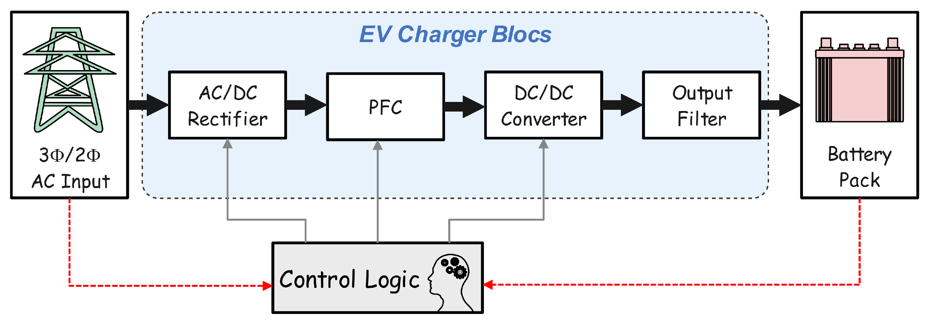
Critical loads like those associated with the military, hospitals, and data centers are constantly present in the system. The government might lose a significant amount of money if these loads fail. Therefore, the V2G mode of operation of EVs is sensitively employed to provide active and reactive power support to essential loads in order to assure the uninterrupted supply to these loads. This EV operation mode, known as the V2L mode of operation, is covered in depth in [18,19,20]. The V2L mode of operation for EV chargers may be viewed as a special case of the V2H and V2V modes. The offboard charging infrastructure, as shown in Figure 2, is located independently and can handle fast charging up to hundreds of kilowatts (kW); onboard charging stations are installed on the electric vehicle (EV) itself and are utilized for lesser power levels [21]. The harmonics have been eliminated, and the reactive power has been regulated using an LC filter [9]. The charging stations we have in our houses can be used for level 1 charging, which uses modest power. Integrating local power generation, such as renewable energy sources (RESs), into the EV charging infrastructure is one effective way to mitigate the damage [22,23,24,25,26]. Both public and private apps use level 2 charging, which charges the battery pack more quickly than level 1 charging. The quickest and most popular charging method is level 3 charging. There are available unidirectional and bidirectional charging techniques. They could either have two stages or only one [8]. In a two-stage EV charger, two converters, AC to DC (first stage) and DC to DC (second stage), are connected in a cascade. The galvanic isolation between the grid and the battery pack is provided by the second-stage converter, which reduces the ripple on the battery side [25]. Bidirectional chargers offer the advantage of allowing the car to run, while chargers with unidirectional topologies can only transmit electricity from the utility grid to the vehicle (G2V) grid mode (V2G), where electricity can be transferred between grids via vehicles whenever necessary [26].
A bidirectional EV charger may help with reactive power support in leading or following operations in addition to active power transmission. The cost of compensators like capacitor banks and static VARs will be decreased if EVs are used to adjust reactive power. Vehicle-for-grid (V4G) is the term used to describe this kind of EV charger [25]. A controller based on a standard PI regulator for a two-stage offboard EV charger is one of the several control schemes offered here [27]. The charger is composed of a completely regulated three-phase AC to DC converter followed by a bidirectional buck–boost DC to DC converter. As a result, two unique controllers have been provided for each step. The controller of the AC–DC converter consists of two loops. In the first loop, the current V d c link is regulated by utilizing a regulator PI. The output of the loop generates a reference current I d . That current is compared with the real I d that is provided by the transformation park. The second loop controls our AC–DC converter regarding work on the current I q such as to maintain the current equal to 0. These are reference currents in the dq domain. In addition, these two current components are compared to the real active and reactive current components of the grid current and two PI controllers are used to reduce the mismatch in the outer current loop. The duty cycle for all three phases is developed using a dq/abc transformation, while the first-stage pulses are created using the well-known pulse width modulation (PWM) approach. In the control design of the DC to DC (second stage) converter, the outer loop creates the reference battery current (Ibat), which is then compared to the real value and regulated by the PI controller in the inner loop. The charger is simulated on MATLAB Simulink 2023a in order to collect data on both the input and output of each PI controller. The collected data are used to build an artificial neural network (ANN) model. The model receives the error and the reference as inputs, with its output comprising data from each PI controller. To sum up, we have constructed a robust model with outstanding results in terms of control in both V2G and V4G modes. The paper’s contribution lies in accelerating the EV charger and compensating the grid without the need for additional compensators by employing an artificial neural network (ANN). The ANN plays a crucial role in minimizing the total harmonic distortion (THD) of the signal and enhancing the dynamic response of the system in V2G mode. In V4G mode, the ANN ensures that the reactive power is approximately 0 KVAR, allowing the battery to compensate the grid by utilizing only active power.

2. Model of ANN Based on Input and Output of PID

Artificial neural networks are frequently viewed as a technology that offers an alternative approach to solving complex problems. An artificial neural network is a mathematical model that seeks to replicate the composition and operation of biological brain networks. A neural network is a method of information processing [11,12]. It is composed of a variety of fundamental closely related processing (units) called neurons, which are comparable to genuine brain cells. Numerous weighted links connect these neurons, allowing signals to pass between them. Each neuron reacts with a single outward signal after receiving several impulses through its incoming connections. These networks excel at both learning and identifying patterns. The suggested artificial neural network controller is based on the input and output of the PID controller in order to replace these PIDs with our model. The model is based on the dataset of errors and references as input datasets; for example, we generate datasets of V d c reference and error between V d c ref and V d c measure. These datasets are combined as a script on MATLAB. The script generates a variable name as input V d c . For the output, we extract it as a variable from another script that collects the data from Simulink with the block to the workspace. The function of a PI controller is demonstrated in Equation (1).
C = K p + K i I F ( z )
The model has two layers of inputs, ten hidden layers, and one layer of output, as shown in Figure 3. A basic artificial neuron with an input layer and an output layer is known as a perceptron.
  • Summation function;
  • Activation function.
The inputs to a perceptron are processed by a summation function, followed by an activation function, to produce the desired output, as demonstrated in Figure 4.
The primary purpose of the activation function is to transform the weighted sum of a neuron’s input signals into an output signal, which then serves as the input for the next layer. The activation function, also known as a transfer function, primarily processes the output to feed it into the next adjacent layer or network.
This system used rectified linear unit (ReLU) because the PI controller has linear function. A rectified linear unit, commonly known as ReLU, is a nonlinear activation function that outputs a value of 0 for any negative input and outputs the input value x for any positive input. Its function is represented by the following equation:
f ( x ) = m a x ( 0 , x )
Normalizing data prior to their introduction into the input layer of an artificial neural network (ANN) has proven to be effective. Batch normalization, specifically, standardizes the outputs from each layer before they are input to the next hidden layer. The key benefit of batch normalization lies in its ability to minimize “covariate shift”. During this process, a batch of data V d c , ref, I d , which could be a mini-batch, is normalized to achieve a mean close to 0 and a standard deviation close to 1. Even if the specific distribution of the input data may vary, their mean and variance stay consistent. Additionally, this technique helps reduce the effects that updates to parameters in earlier layers might have on the data distribution in subsequent layers.

3. Topology Design of Charger (V2G and V4G)

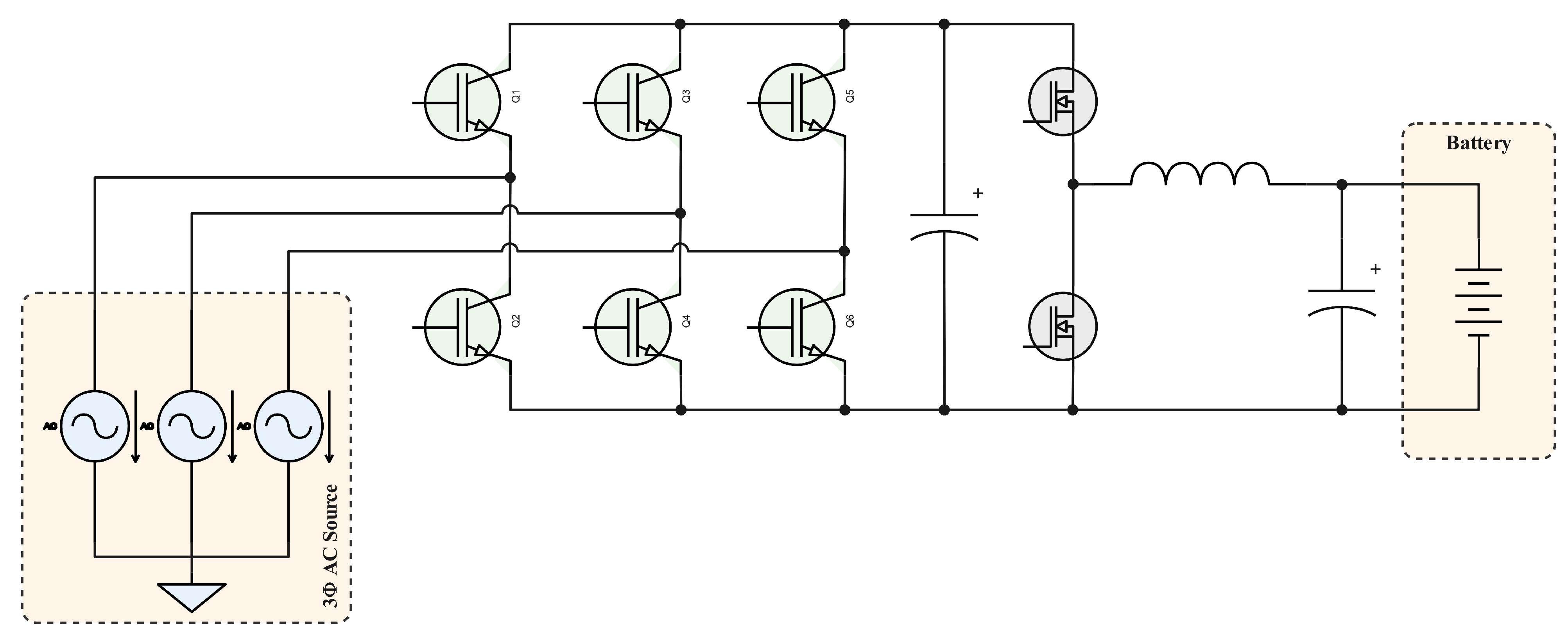
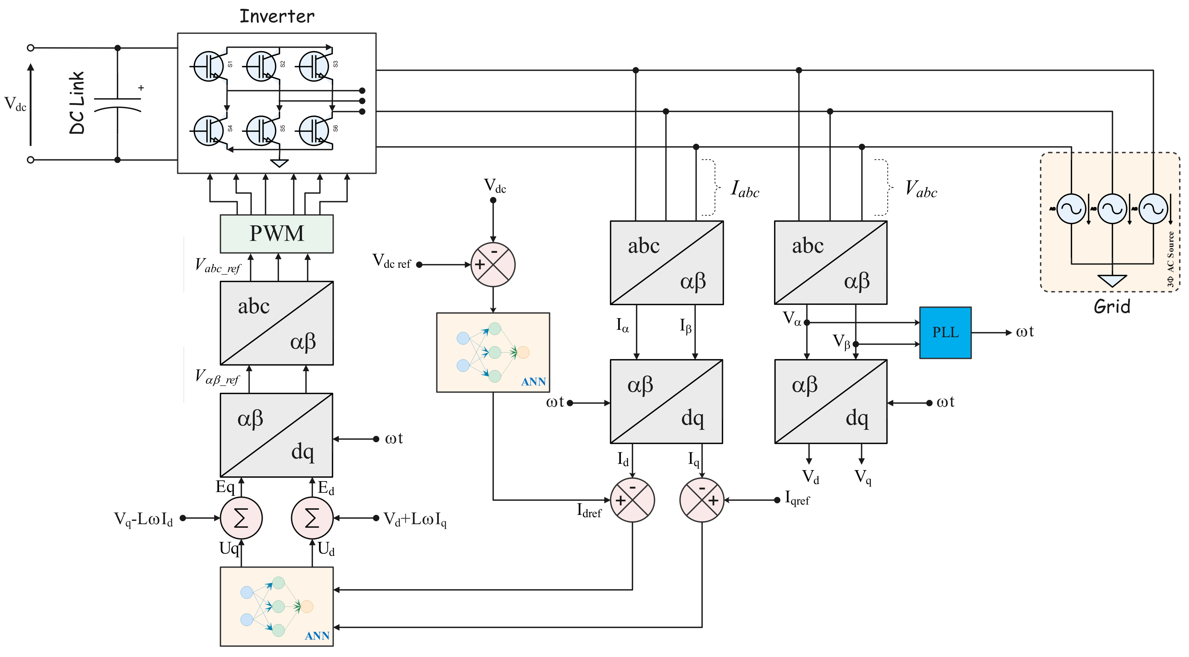
Figure 5 shows the system architecture using AC–DC (first) and DC–DC (second) power. A bipolar transistor with an insulated gate (IGBT) serves as the foundation of both converters. In the AC–DC step, there are six IGBTs employed, but there are only two in the DC–DC stage. Each switch has a voltage blocking limit of V d c . While the second stage is connected to a battery, the first stage is directly connected to the three-phase grid. Figure 6 illustrates the architecture of our controller design, which uses an ANN to manage the system.

4. Controller Architecture

4.1. AC–DC Controller

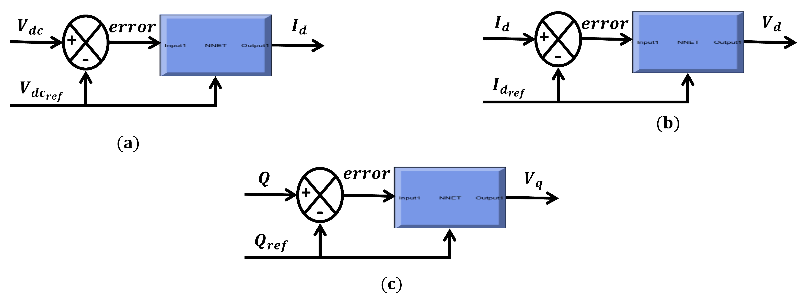
Determining active–reactive power at the AC side of the EV charger in the dq domain is the first difficult task. The ABC domain is transformed into the dq domain via the park transformation. Park generates V d , V q , I d , and I q as well. Current I d is determined by comparing the voltage difference between the link and the reference, and a model ANN controller helps to reduce mistakes as shown in Figure 7a. A model ANN controller maintains the reference I d ref equal to I d , as provided in Figure 7b. The final model ANN controller is illustrated in Figure 7c; this model maintains the reference of reactive power equal to the reactive power that has been measured, and the output of this model is voltage U d . We combined U d , U q , and decoupling; this coupling is shown in Equations (2) and (3). While Figure 8 illustrates the ANN model for the buck-boost converter.
V d + U d + L ω I q = E d
V q + U q L ω I d = E q

4.2. DC–DC Controller

In the control design of the DC to DC (second stage) converter, the outer loop creates the reference battery current (Ibat), which is then compared to the real value and regulated by the ANN controller, as shown in Figure 9, illustrating the main role of the switch between the buck and boost modes.

5. Proposed System in Simulation and Experimental Modes

5.1. Proposed System in Simulation Mode

This simulation presented our system in MATLAB Simulink. First, we have a grid, and, next, we used an AC–DC bidirectional inverter that is controlled by an ANN controller. The V d c link is stabilized with the capacitor maintained at a value of 400 V. In the second stage, a DC–DC converter works as a boost, and the boost converter maintains the voltage V d c link at 800 V. In this mode, the system works in V2G for inductive and capacitive discharging, and the reactive power for V2G is negative for discharge capacitive and positive for discharger inductive. The reactive power is null for mode V4G because the vehicle works as a compensator.

5.2. Implementation of the Proposed System

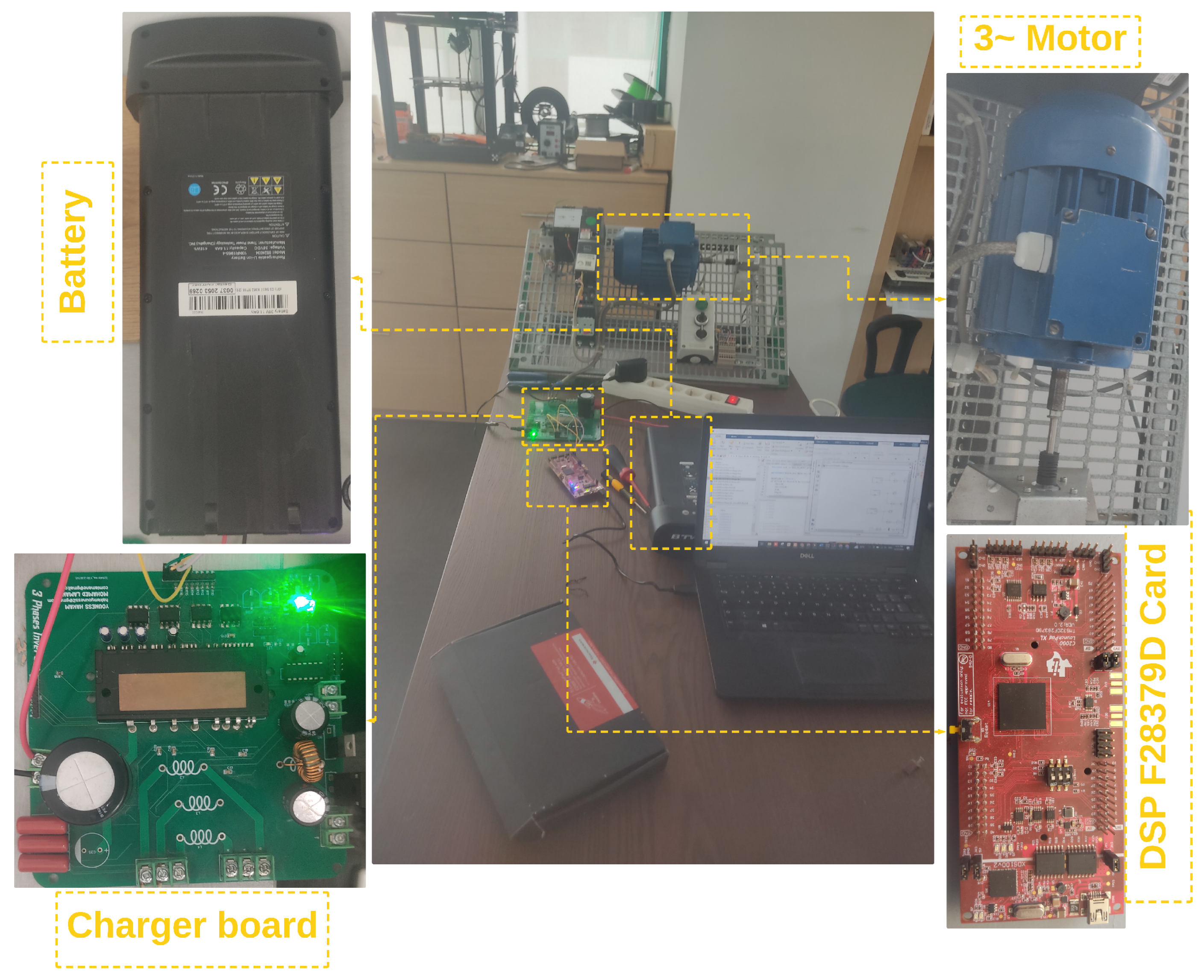
Figure 10 provides a detailed illustration of the proposed system’s sophisticated design and implementation, offering a thorough overview of its functionality and essential components. These components include a battery, a boost converter, and an inverter board. Central to this configuration is the advanced inverter card, designed to facilitate bidirectional power flow, crucial for sustainable energy exchange. Meticulously crafted, the inverter card incorporates an intelligent power module (IPM) solution, enabling it to operate as both a rectifier and inverter. This adaptability ensures that it can smoothly adjust to fluctuating energy demands and grid conditions, optimizing performance in various scenarios, such as compensating the grid by using electric vehicle battery (EVB) in vehicle-for-grid (V4G) mode.

6. Results and Discussion

6.1. Results of Proposed Model

Figure 11 and Figure 12 present extensive information about the proposed ANN model. We utilized the Levenberg–Marquardt algorithm for training, which lasted about 18 h, to perfect the model for reactive power. Additionally, we employed the same method to develop models for active power, V d c link, and direct current.
The results of this model are perfect; the performance of the training and validation is about 2.7023 × 10³. The value of R is the correlation coefficient. If the R-value is large, then the MSE value is much smaller than the mean target variance. This indicates that the net has successfully managed to model most of the variation in the input target transformation.

6.2. Simulation Results

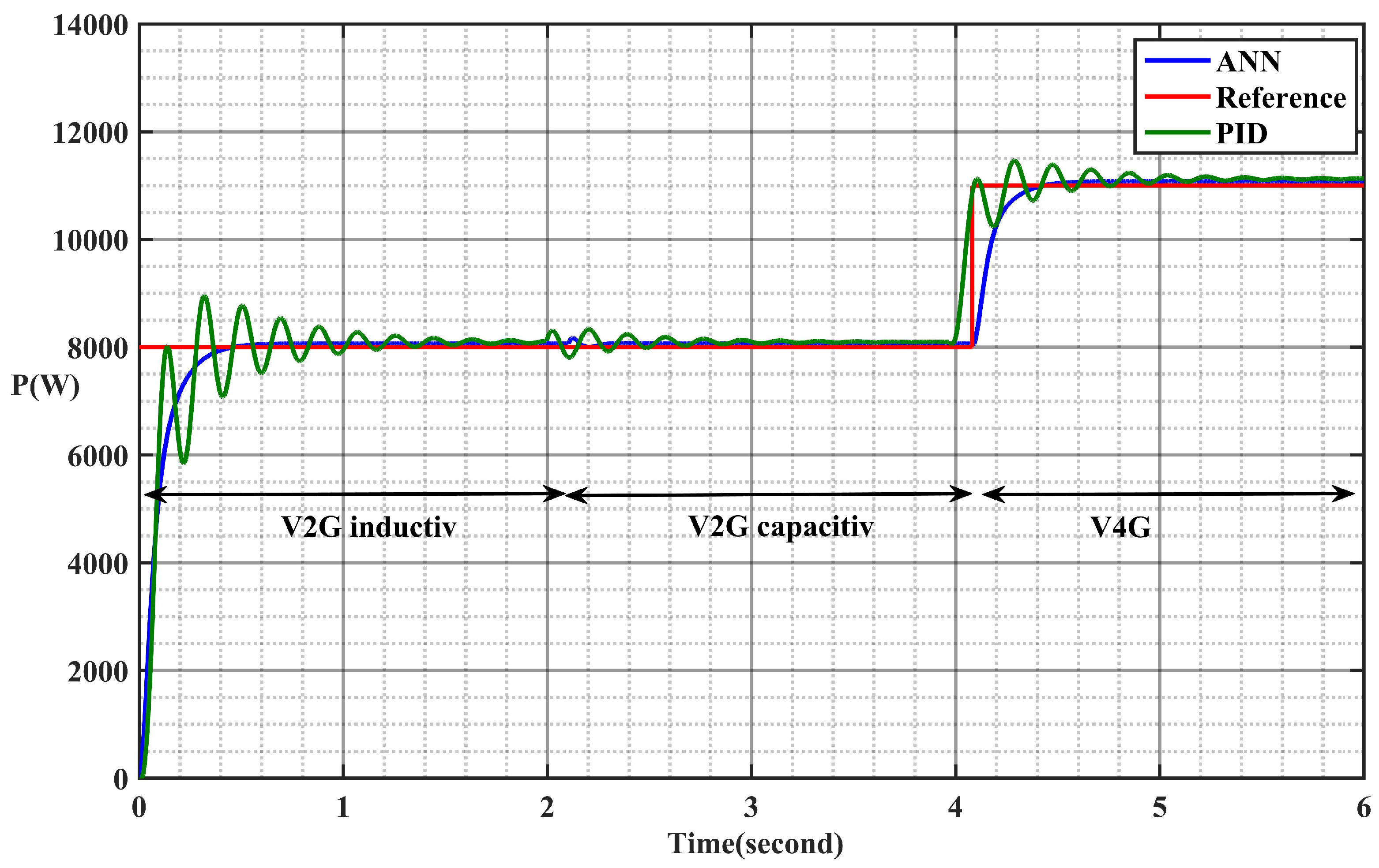
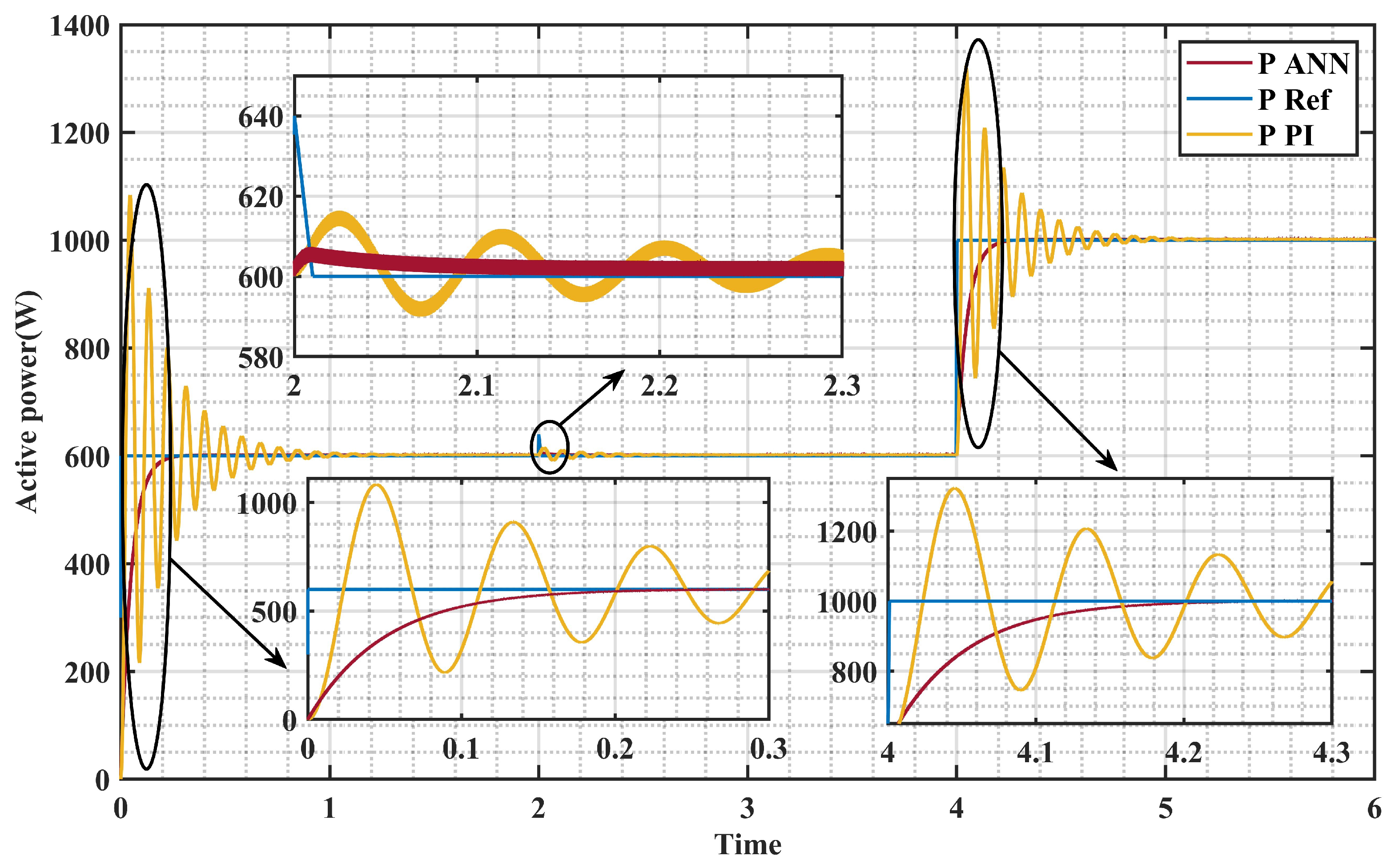
Several articles primarily emphasize the utilization of PID and model predictive controllers as the preferred techniques for managing the active and reactive power in EV chargers. However, this article introduces an alternative approach rooted in artificial intelligence, which proves to be highly effective. The results demonstrate that this AI-based method exhibits minimal overshoot and rapid response times for both active and reactive power, as depicted in Figure 13. In particular, the active power in the V2G and V4G modes remains stable, closely following the reference values set by the ANN algorithm. In contrast, the PID controller exhibits substantial overshoot and extended response times. It is worth noting that the reference values for active power are 8 kW for V2G (both inductive and capacitive) and 11 kW for V4G mode. The simulation of the system was conducted using MATLAB Simulink, employing the parameters outlined in Table 1 for accuracy and precision. The simulation setup is grounded on a grid delivering a stable voltage of 415 volts. Ceramic capacitors were strategically integrated to ensure the stabilization of the voltage link between the buck–boost converter and the inverter–rectifier, facilitating seamless bidirectional power flow. Notably, the control mechanism of the system is predominantly governed by references to both active power and reactive power, ensuring efficient and reliable operation under various conditions.
P is 8000 W for capacitive and inductive V2G mode, and, for the last mode, the active power is 11,000 W because the reactive power is equal to 0, which means the apparent power is equal to the active power P = S and the power factor is equal to 1. The apparent puissance is the addition of active power and reactive power; we have a charger with an 11 KVA, but, for the first and second mode, the active and reactive power are different.
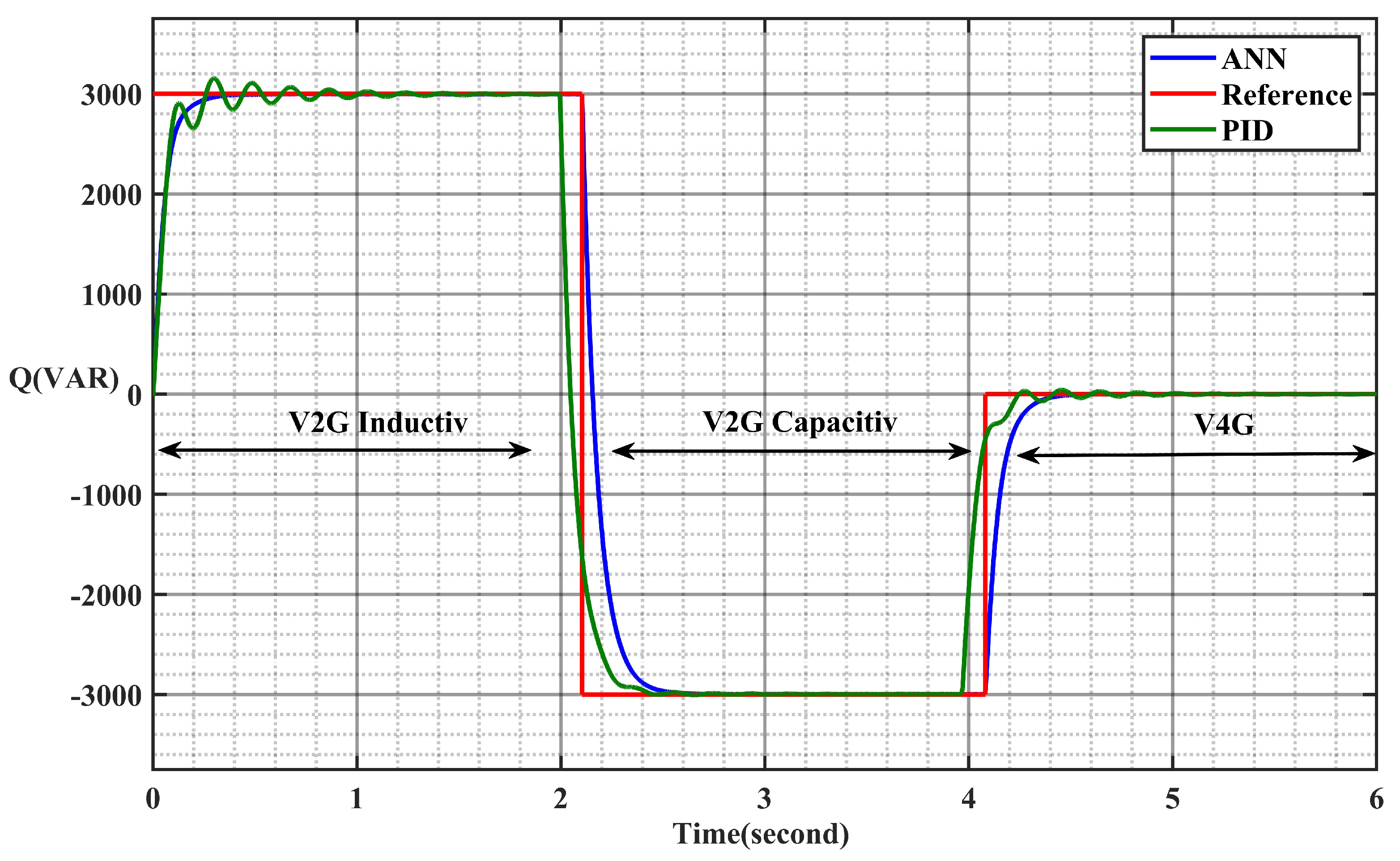
Figure 14 displays remarkable performance in terms of reactive power, featuring swift response times and notably diminished overshooting, in stark contrast to the results obtained with the PID controller. The reference values for reactive power are set at 3 kW for V2G inductive mode and −3 kW for capacitive mode. Notably, in V4G mode, the reactive power becomes null, courtesy of the EV’s battery efficiently compensating for it. This mode showcases exceptional efficiency, obviating the necessity for compensation capacitors.
Figure 15 provides insights into the voltage and current characteristics of the grid under three distinct operational modes. Utilizing the PID controller yielded results that failed to meet acceptable standards, marked by substantial overshooting. Moreover, shifting to a different mode introduced distortions in both the voltage and current waveforms, leading to increased harmonic content.
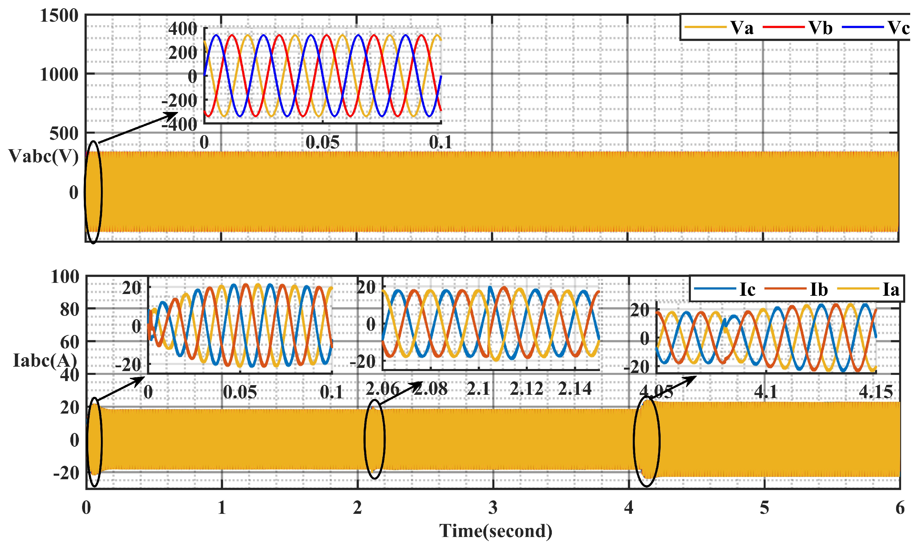
Conversely, Figure 16 demonstrates that the ANN method yields more stable and commendable results. Even during mode transitions, such as the shift from V2G to V4G, the voltage and current maintain their stability and exhibit well-balanced behaviors.
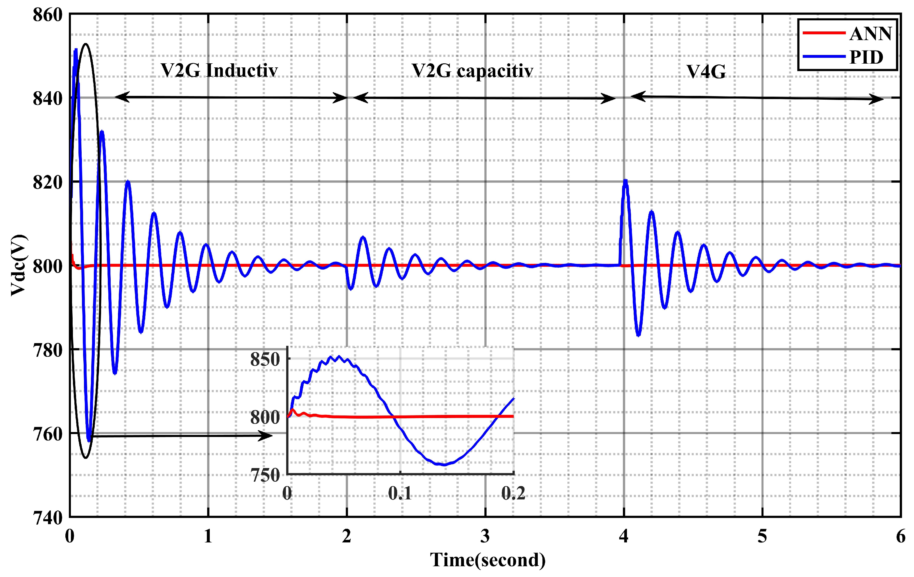
Figure 17 demonstrates the voltage of the V d c link, which serves as a representation of the output voltage generated by the rectifier/converter. Remarkably, this V d c link voltage demonstrates a flawless performance when utilizing the ANN method. It remains devoid of any overshooting tendencies, notably diverging from the PID controller’s behavior, particularly when transitioning between operational modes.
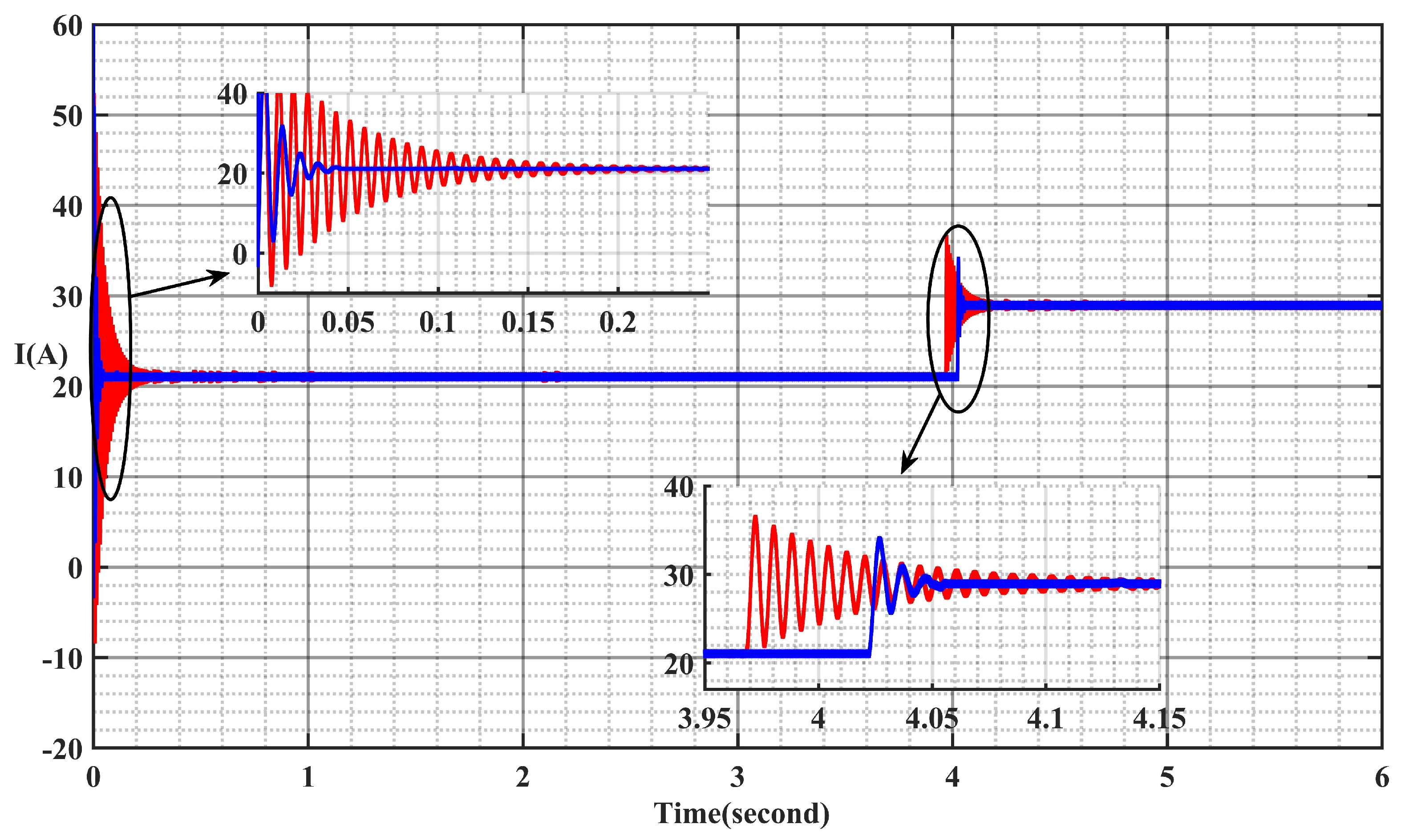
Figure 18 illustrates the variation in the current of the battery; it is the most important parameter for an EV charger; the current of the battery in the V2G inductive and capacitive modes is very stable for the ANN method, while it has a large overshoot in the first simulation at 500 A as well as when we change the mode from V2G to V4G. The current in V2G mode is 20 A, while it is 21 A in V4G mode.

6.3. Experimental Results

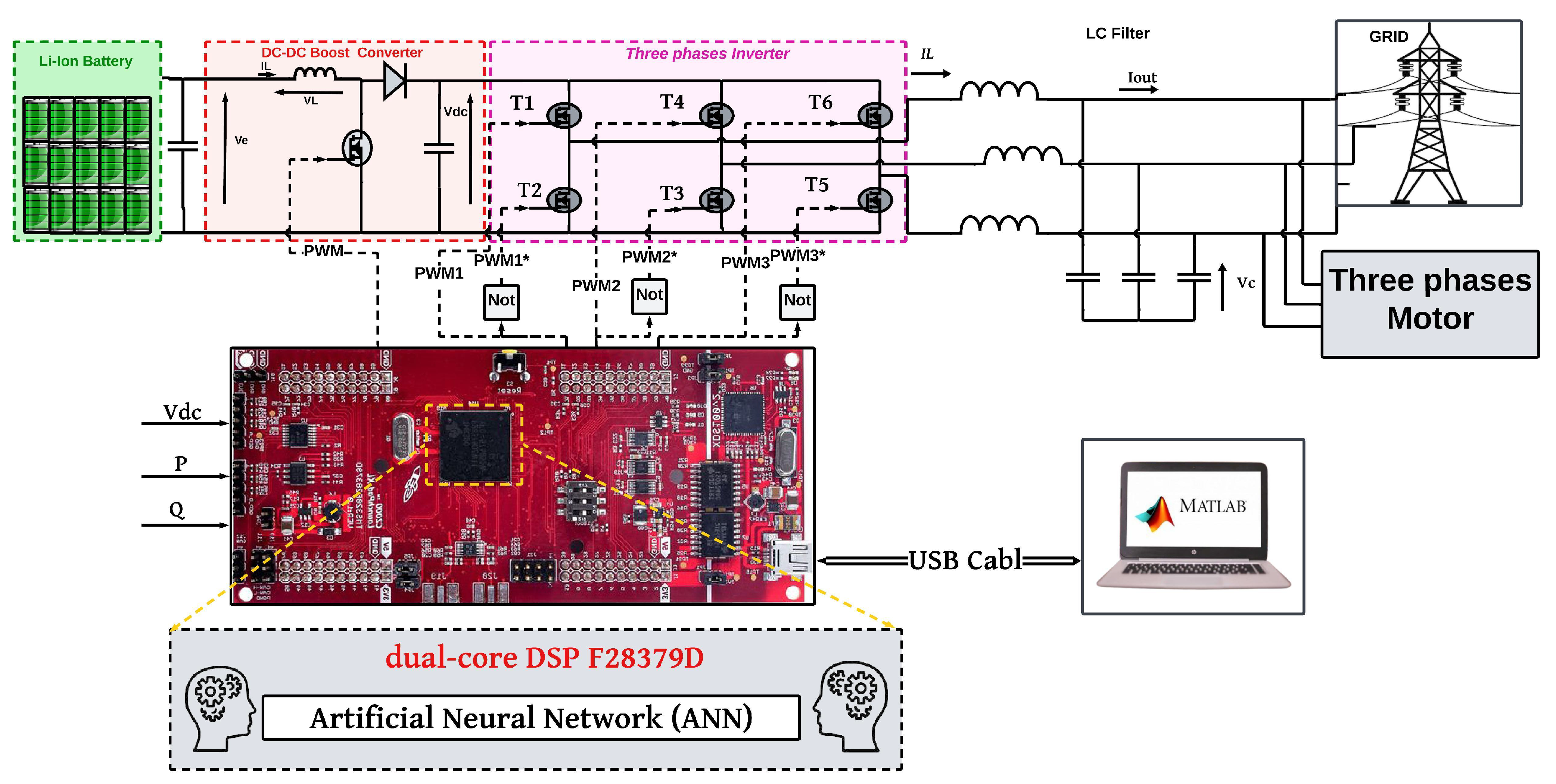
In the real world of the system, we used DSP F28379D as our microcontroller, and we installed it as a package in MATLAB Simulink in order to permit uploading the code into a DSP board. Figure 19 demonstrates the variation in the active power in three modes, such as that the value of P is about 500 W in the V2G inductive/capacitive modes while, in V4G mode, the value is about 1 kW. The results of active power are based on the condition of the load.
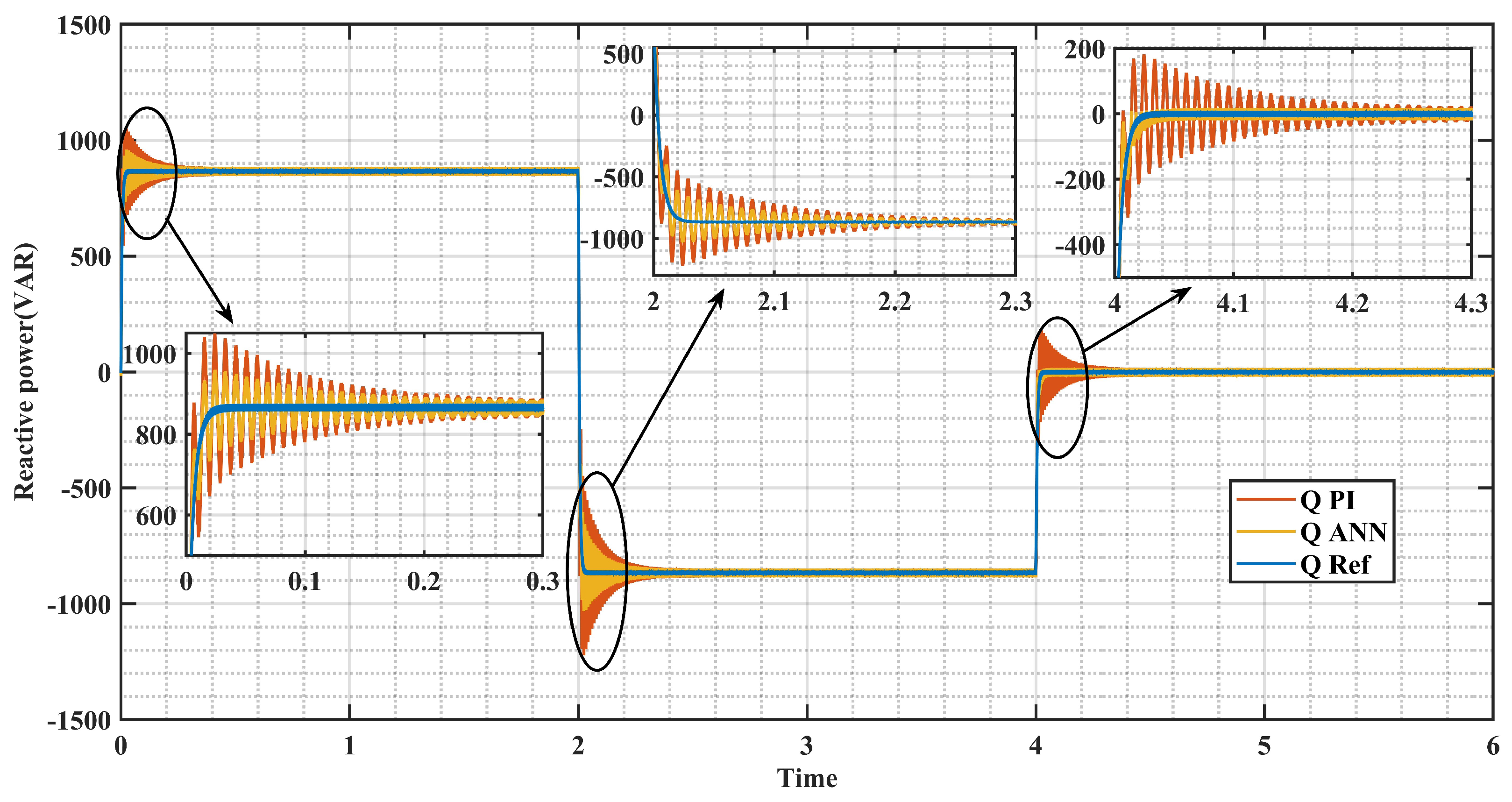
Figure 20 illustrates the variation in the reactive power. The value of Q in mode 1 (0 to 2 s) is about +865 VAR. This value demonstrates that the grid injects the reactive power in the load, while the value of Q is about −865 VAR in mode 2 (2 to 4 s). This mode is used to demonstrate the possibility to inject into the grid. V4G (4 to 6 s) demonstrates the novelty of our algorithm, ensuring that the battery can compensate the grid, such as when the reactive power is about 0 VAR. The V4G mode is a new technique that enables the battery to compensate the grid without using capacitor compensators. The benefit of this new method is to minimize the cost of the compensators, and the driver of an electric vehicle can choose to compensate the grid and earn some money.
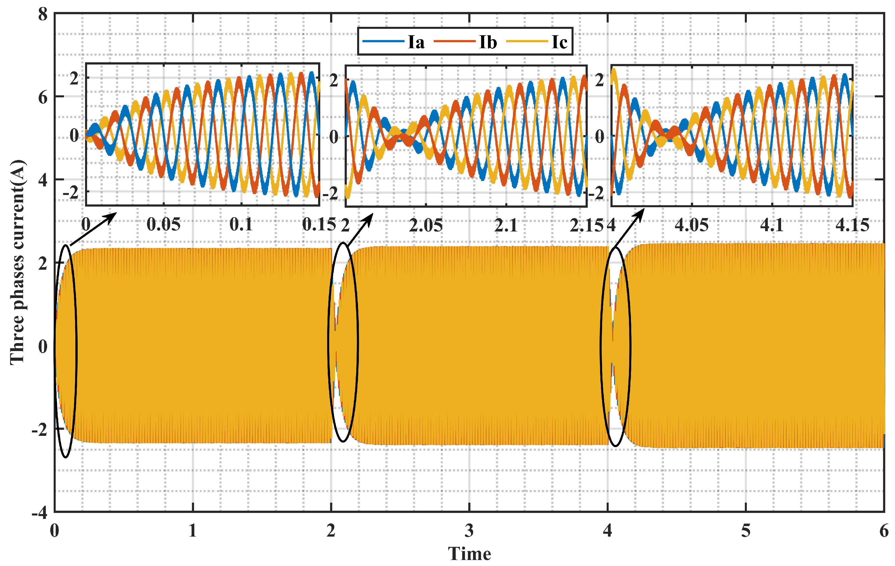
Figure 21 and Figure 22 offer insights into the voltage and current characteristics of the grid under three distinct operational modes. The use of a PID controller resulted in an unacceptable performance, characterized by significant overshooting. Additionally, switching to a different mode introduced distortions in both the voltage and current waveforms, increasing the harmonic content. In contrast, the ANN method produced more stable and favorable results. Even during mode transitions, such as shifting from V2G to V4G, the voltage and current remained stable and demonstrated well-behaved characteristics in terms of the total harmonic distortion (THD) and response time.
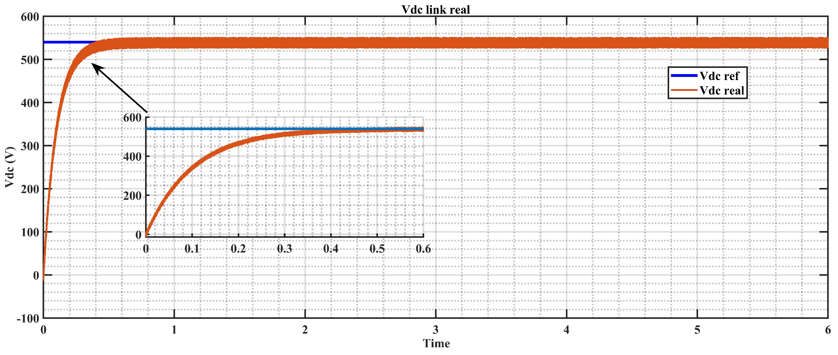
Figure 23 provides a detailed illustration of the system’s performance. It notably shows a consistent DC capacitor link voltage of 540 volts, meticulously maintained to ensure the stability of the DC link capacitor voltage at this uniform level. This sustained voltage is crucial for promoting the system sustainability, optimizing the energy efficiency, and enhancing the overall performance. By converting the DC voltage into a sinusoidal waveform, the inverter enables the seamless integration with the grid, facilitating efficient energy transfer and utilization. The use of sinusoidal waveforms also helps to minimize harmonic distortion and improve the quality of the power supplied to the grid.
The current of the battery is the most crucial parameter for an EV charger. Figure 24 illustrates that the battery current in the V2G inductive and capacitive modes remains very stable with the ANN method. In contrast, using a PI controller results in significant overshoot in the battery current during the transition from the V2G mode to the V4G mode. The battery current is approximately 2.20 A in both the V2G and V4G modes.
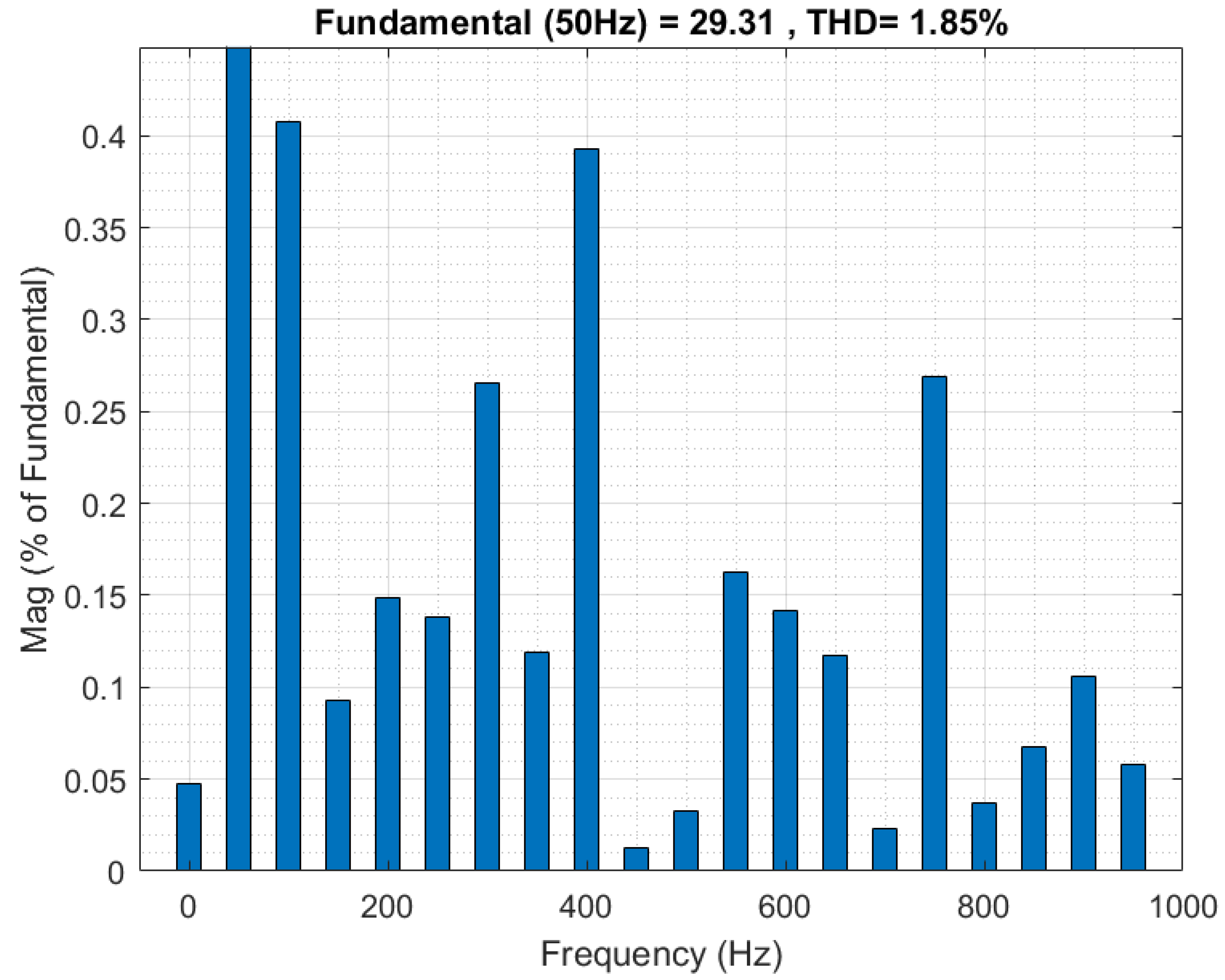
Figure 25 depicts the correlation between the total harmonic distortion (THD) and output voltage, showing that the optimal controller performance is achieved at an output voltage of V c = 220 V and a current of I = 0.70 A. The main objective of the proposed system is to improve the voltage quality by reducing the THD. In performance comparisons of waveforms and THD, the proposed controller recorded a THD of 2.56 % , which is approximately 1.85 % lower than that achieved by other algorithms. Table 2 outlines the system parameters used in the experimental mode to derive real-world data, and Table 3 highlights the superior efficacy of our proposed algorithm. It shows a significantly faster response time—shorter by 0.1 s—compared to the competing algorithms, and a notably reduced THD of 0.71 % , in contrast to the 2.569999 % THD reported in Ref. [28], while Table 4 demonstrates the comparative performance of the proposed system and PI-FUZZY proposed in [29].

7. Conclusions

This study introduces an innovative control strategy for a bidirectional battery charger that effectively integrates power injection into the smart grid while compensating for reactive power using an electric vehicle battery. The use of an artificial neural network (ANN) controller ensures minimal error and optimal performance, with sinusoidal pulse width modulation (SPWM) generated for the AC–DC inverter. The system, simulated in MATLAB Simulink and controlled by a DSP F28379D board, was tested on a three-phase motor. The key results highlight the effectiveness of the ANN algorithm, achieving a total harmonic distortion (THD) of 1.85 % , significantly lower than the 2.56 % THD of the MPC algorithm. Additionally, the ANN-based system demonstrated minimal response time and no overshoot, crucial factors that allow for the rapid and efficient charging of electric vehicles. The system also achieved effective grid compensation, with the reactive power neutralized to 0 KVAR. These findings confirm the ANN-based control strategy’s potential for enhancing the grid stability and power quality while ensuring the swift charging of electric vehicles.

Author Contributions

Conceptualization, Y.H.; Methodology, A.G.; Software, M.T.; Validation, Y.H. and B.E.; Formal analysis, B.E.; Writing—original draft, Y.H.; Writing—review & editing, A.G. and M.T.; Supervision, A.G., M.T. and B.E. All authors have read and agreed to the published version of the manuscript.

Funding

This research received no external funding.

Data Availability Statement

The data presented in this study are available on request from the corresponding authors.

Conflicts of Interest

The authors declare no conflicts of interest.

References

  1. Rahman, K.; Hashimoto, J.; Orihara, D.; Ustun, T.S.; Otani, K.; Kikusato, H.; Kodama, Y. Reviewing Control Paradigms and Emerging Trends of Grid-Forming Inverters—A Comparative Study. Energies 2024, 17, 2400. [Google Scholar] [CrossRef]
  2. Pan, W.; Yu, X.; Guo, Z.; Qian, T.; Li, Y. Online EVs Vehicle-to-Grid Scheduling Coordinated with Multi-Energy Microgrids: A Deep Reinforcement Learning-Based Approach. Energies 2024, 17, 2491. [Google Scholar] [CrossRef]
  3. Amiruddin, A.; Dargaville, R.; Liebman, A.; Gawler, R. Integration of Electric Vehicles and Renewable Energy in Indonesia’s Electrical Grid. Energies 2024, 17, 2037. [Google Scholar] [CrossRef]
  4. Rathore, A.K.; Prasanna, U.R. Comparison of soft-switching voltage-fed and current-fed bi-directional isolated dc/dc converters for fuel cell vehicles. In Proceedings of the IEEE International Symposium on Industrial Electronics, Hangzhou, China, 28–31 May 2012; pp. 252–257. [Google Scholar]
  5. Salmasi, F.R. Control strategies for hybrid electric vehicles: Evolution, classification, comparison, and future trends. IEEE Trans. Veh. Technol. 2007, 56, 2393–2404. [Google Scholar] [CrossRef]
  6. Yilmaz, M.; Krein, P.T. Review of battery charger topologies, charging power levels and infra-structure for plug-in electric and hybrid vehicles. IEEE Trans. Power Electron. 2013, 28, 2151–2169. [Google Scholar] [CrossRef]
  7. Asthana, P.; Verma, V. PV Fed Current Controlled Low Stress High Gain Converter for Battery Charging Applications. In Proceedings of the 2020 IEEE International Conference on Power Electronics, Smart Grid and Renewable Energy (PESGRE2020), Cochin, India, 2–4 January 2020; pp. 1–4. [Google Scholar]
  8. Tran, V.T.; Islam, M.R.; Muttaqi, K.M.; Sutanto, D. An on-board V2X electric vehicle charger based on amorphous alloy high-frequency magnetic-link and SiC power devices. In Proceedings of the 2019 IEEE Industry Applications Society Annual Meeting, Baltimore, MD, USA, 29 September–3 October 2019; pp. 1–6. [Google Scholar] [CrossRef]
  9. Ahessab, H.; Hakam, Y.; Gaga, A.; Elhadadi, B. ANN-Fuzzy Hybrid Control Strategy for MPPT of Grid-connected PV System with Battery Storage under Fast-charging Atmospheric Condition. In Recent Advances in Electrical and Electronic Engineering; Betham Science: Sharjah, United Arab Emirates, 2024. [Google Scholar] [CrossRef]
  10. Tran, V.T.; Rabiul, I.M.; Muttaqi, K.M.; Sutanto, D. A novel universal magnetic power plug to facilitate V2V/ V2G/ G2V/ V2H connectivity for future grid infrastructure. In Proceedings of the 2020 IEEE Industry Applications Society Annual Meeting, Detroit, MI, USA, 10–16 October 2020; pp. 1–7. [Google Scholar] [CrossRef]
  11. Dicorato, M.; Forte, G.; Trovato, M.; Muñoz, C.B.; Coppola, G. An integrated DC microgrid solution for electric vehicle fleet management. IEEE Trans. Ind. Appl. 2019, 55, 7347–7355. [Google Scholar] [CrossRef]
  12. Hsu, Y.-C.; Kao, S.-C.; Ho, C.-Y.; Jhou, P.-H.; Lu, M.-Z.; Liaw, C.-M. On an electric scooter with G2V/ V2H/ V2G and energy harvesting functions. IEEE Trans. Power Electron. 2018, 33, 6910–6925. [Google Scholar] [CrossRef]
  13. Kesler, M.; Kisacikoglu, M.C.; Tolbert, L.M. Vehicle-to-grid reactive power operation using plug-in electric vehicle bidirectional offboard charger. IEEE Trans. Ind. Electron. 2014, 61, 6778–6784. [Google Scholar] [CrossRef]
  14. Monteiro, V.; Pinto, J.G.; Afonso, J.L. Operation modes for the electric vehicle in smart grids and smart homes: Present and proposed modes. IEEE Trans. Veh. Technol. 2016, 65, 1007–1020. [Google Scholar] [CrossRef]
  15. Yilmaz, M.; Krein, P.T. Review of the impact of vehicle-to-grid technologies on distribution systems and utility interfaces. IEEE Trans. Power Electron. 2013, 28, 5673–5689. [Google Scholar] [CrossRef]
  16. Yuan, J.; Dorn-Gomba, L.; Callegaro, A.D.; Reimers, J.; Emadi, A. A review of bidirectional on-board chargers for electric vehicles. IEEE Access 2021, 9, 51501–51518. [Google Scholar] [CrossRef]
  17. Wang, X.; Liu, Y.; Qian, W.; Wang, B.; Lu, X.; Zou, K.; González-Santini, N.; Karki, U.; Peng, F.Z.; Chen, C. A 25 kW SiC universal power converter building block for G2V, V2G, and V2L applications. In Proceedings of the 2018 IEEE International Power Electronics and Application Conference and Exposition (PEAC), Shenzhen, China, 4–7 November 2018; pp. 1–6. [Google Scholar] [CrossRef]
  18. Liu, Y.; Wang, X.; Qian, W.; Janabi, A.; Wang, B.; Lu, X.; Zou, K.; Chen, C.; Peng, F.Z. DC voltage control of inverter interfaced dual active bridge converter for V2L applications. In Proceedings of the 2019 IEEE 7th Workshop on Wide Bandgap Power Devices and Applications (WiPDA), Raleigh, NC, USA, 29–31 October 2019; pp. 319–324. [Google Scholar]
  19. Yazdani, A.; Iravani, R. Voltage-Sourced Converters in Power Systems: Modeling, Control, and Applications; Wiley: Hoboken, NJ, USA, 2010. [Google Scholar]
  20. Longo, M.; Foiadelli, F.; Yaïci, W. Electric vehicles integrated with renewable energy sources for sustainable mobility. In New Trends in Electrical Vehicle Powertrains; Martinez, L.R., Ed.; IntechOpen: London, UK, 2019. [Google Scholar]
  21. Ces, T. Transportation options in a carbon constrained world: Hybrids, plug-in hybrids, biofu-els, fuel cell electric vehicles, and battery electric vehicles. Int. J. Hydrogen Energy 2009, 34, 9279–9296. [Google Scholar] [CrossRef]
  22. Liu, L.; Kong, F.; Liu, X.; Peng, Y.; Wang, Q. A review on electric vehicles interacting with renew-able energy in smart grid. Renew. Sustain. Energy Rev. 2015, 51, 648–661. [Google Scholar] [CrossRef]
  23. Williamson, S.S.; Rathore, A.K.; Musavi, F. Industrial Electronics for Electric Transportation: Current State-of-the-Art and Future Challenges. IEEE Trans. Ind. Electron. 2015, 62, 3021–3032. [Google Scholar] [CrossRef]
  24. Chan, C.C.; Bouscayrol, A.; Chen, K. Electric, hybrid, and fuel-cell vehicles: Architectures and modeling. IEEE Trans. Veh. Technol. 2010, 59, 589–598. [Google Scholar] [CrossRef]
  25. Clement-Nyns, K.; Haesen, E.; Driesen, J. The impact of charging plug-in hybrid electric vehi-cles on a residential distribution grid. IEEE Trans. Power Syst. 2010, 25, 371–380. [Google Scholar] [CrossRef]
  26. Khaligh, A.; Dusmez, S. Comprehensive topological analysis of conductive and inductive charging solutions for plug-in electric vehicles. IEEE Trans. Veh. Technol. 2012, 61, 3475–3489. [Google Scholar] [CrossRef]
  27. Kisacikoglu, M.C.; Ozpineci, B.; Tolbert, L.M. Examination of a PHEV bidirectional charger for V2G reactive power compensation. In Proceedings of the IEEE APEC Expo, Palm Springs, CA, USA, 21–25 February 2010; pp. 458–465. [Google Scholar]
  28. Xingwu, Y.; Hongchao, J.; Wei, G. Model Predictive Control of Single Phase Grid-connected Inverter. In Proceedings of the 2014 IEEE PES Asia-Pacific Power and Energy Engineering Conference (APPEEC), Hong Kong, China, 7–10 December 2014; pp. 1–4. [Google Scholar] [CrossRef]
  29. Sayed, K.; Gabbar, A.H. Electric Vehicle to Power Grid Integration Using Three-Phase Three-Level AC/DC Converter and PI-Fuzzy Controller. Energies 2016, 9, 532. [Google Scholar] [CrossRef]
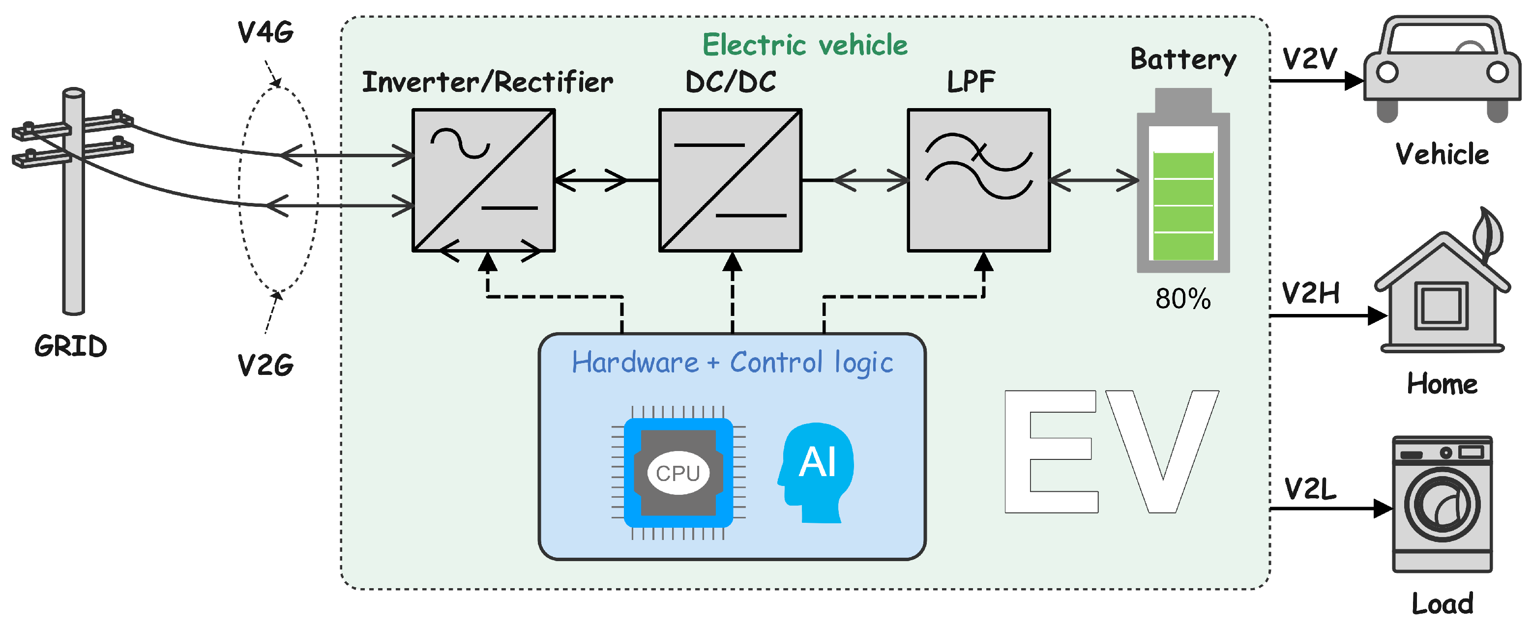
Figure 1. Multiple modes of V2X system.
Energies 17 03095 g001
Figure 2. Schematic of EV charger.
Energies 17 03095 g002
Figure 3. Internal architecture of ANN.
Energies 17 03095 g003
Figure 4. Architecture of ANN controller.
Energies 17 03095 g004
Figure 5. Topology design for V2X system.
Energies 17 03095 g005
Figure 6. Architecture of DC–AC controller.
Energies 17 03095 g006
Figure 7. Models of ANN controllers. (a) voltage link; (b) direct current; (c) reactive power.
Energies 17 03095 g007
Figure 8. Controller ANN in DC–DC converter.
Energies 17 03095 g008
Figure 9. Diagram of the proposed system architecture.
Energies 17 03095 g009
Figure 10. Real-world apsects of the proposed system.
Energies 17 03095 g010
Figure 11. Performance of training model algorithm.
Energies 17 03095 g011
Figure 12. Training model algorithm.
Energies 17 03095 g012
Figure 13. The active power for both V2G and V4G modes, comparing the PID and ANN methods.
Energies 17 03095 g013
Figure 14. The reactive power for both V2G and V4G modes, comparing the PID and ANN methods.
Energies 17 03095 g014
Figure 15. The voltage and current of the grid under the influence of the PID controller in the three different modes.
Energies 17 03095 g015
Figure 16. The voltage and current profiles of the grid across the three modes under the control of the ANN controller.
Energies 17 03095 g016
Figure 17. The voltage link ( V d c ) across the three modes with both ANN and PID controllers.
Energies 17 03095 g017
Figure 18. The battery current in all three modes under the application of both the PID and ANN methods.
Energies 17 03095 g018
Figure 19. The active power for both V2G and V4G modes.
Energies 17 03095 g019
Figure 20. The reactive power for both V2G and V4G modes.
Energies 17 03095 g020
Figure 21. The voltage of the motor in modes V2G and V4G.
Energies 17 03095 g021
Figure 22. The current of the grid in both modes, V2G and V4G.
Energies 17 03095 g022
Figure 23. The voltage link ( V d c ) in the real world.
Energies 17 03095 g023
Figure 24. The battery current in the real world.
Energies 17 03095 g024
Figure 25. The total harmonic distortion.
Energies 17 03095 g025
Table 1. Parameters of system in simulation mode.
DescriptionVariableValue
Supply voltage V s 380 V
Sypply frequencyf50 Hz
DC link capacitor voltage V d c 800 V
DC link capacitor C d c 470 µF
Sampling time T s 0.0002 s
Inductor Filter L f 10 mH
Capacitor Filter L f 1.2 µF
Power of gridP12 kVA
Table 2. System parameters.
DescriptionVariableValue
Supply voltage V s 380 V
Sypply frequencyf50 Hz
DC link capacitor voltage V d c 540 V
DC link capacitor C d c 470 µF
Inductor L b 5 mH
ResistorR0.1 ohm
Sampling time T s 0.0002 s
power of motorS1.1 kVA
Inductor Filter L f 5 mH
Inductor capacitor L f 1 µF
Table 3. Comparison table of algorithms.
AlgorithmsResponse TimeTHD
MPC [28]0.8 2.56 %
Algorithm proposed0.01 1.85 %
Table 4. Table of system performance comparison.
ParametersControlResponse Time (s)Peak Overshoot
DC voltagePI [29]0.75 24 %
PI-FUZZY [29]0.25 24 %
Utilized PI controller0.90 22 %
proposed control (ANN)0.1 1 %
DC currentPI [29]0.85 33 %
PI-FUZZY [29]0.25 33 %
Utilized PI controller0.1 30 %
proposed control (ANN)0.01 0.2 %
Active PowerPI [29]0.76 30 %
PI-FUZZY [29]0.5 40 %
Utilized PI controller0.74 30 %
proposed control (ANN) 0.4 % 1 %
Reactive PowerPI [29]1.2 450 %
PI-FUZZY [29]0.6 300 %
Utilized PI controller0.3 100 %
proposed control (ANN)0.2 4 %
Disclaimer/Publisher’s Note: The statements, opinions and data contained in all publications are solely those of the individual author(s) and contributor(s) and not of MDPI and/or the editor(s). MDPI and/or the editor(s) disclaim responsibility for any injury to people or property resulting from any ideas, methods, instructions or products referred to in the content.