Abstract
At present, there is a global rise in electricity consumption, leading to an accelerated depletion of natural resources due to the reliance on fossil fuels to fulfill this energy demand. Consequently, there exists a worldwide emphasis on enhancing the proportion of renewable energy sources in electricity generation. Biomass, as a renewable energy source, presents a viable alternative to certain fossil energy sources for combustion in electricity generation. This study focuses on a 660 MW coal-fired power plant as the subject of investigation, employing Aspen Plus simulation software (V11) to replicate the operational dynamics of the plant. A model of the direct mixed combustion biomass system within the coal-fired boiler is constructed, and its accuracy is validated against operational data obtained from the power plant. Moreover, a model elucidating the direct co-combustion of biomass in a coal-fired boiler, augmented by flue gas recirculation, was developed through the integration of biomass pre-treatment and flue gas recirculation technologies. This study explores the impacts of varying biomass blending ratios and flue gas recirculation on parameters, including flue gas volume, power generation efficiency, boiler performance, water vapor content, and emissions of pollutants. These findings indicate an inverse relationship between the mixing ratio and various performance metrics as follows: power generation, boiler efficiency, as well as NOX and SO2 content, with larger mixing ratios resulting in diminished values. Furthermore, the incorporation of flue gas recirculation was observed to mitigate furnace temperatures and suppress NOX emissions.
1. Introduction
The widespread utilization of coal as a primary fossil energy source in power plants is a prevalent practice driven by the escalating global demand for electricity in tandem with economic development. However, this reliance on coal has resulted in a depletion of traditional fossil fuel reserves and a surge in pollutant emissions. In response, the concurrent combustion of coal and biomass in coal-fired boilers emerges as a complementary energy solution, offering a promising strategy to address both fuel scarcity and environmental concerns [1]. Biomass is often referred to as “zero-carbon energy” due to its capacity for carbon neutrality. This is because the carbon dioxide generated during its utilization can be naturally absorbed through processes such as tree planting, thereby achieving a balance in carbon emissions [2,3]. Simultaneously, numerous studies have demonstrated that substituting a portion of coal with biomass in power generation effectively reduces atmospheric pollution, specifically the emissions of SOX, NOX, and PM2.5 (the concentration in ambient air of dust or drift dust with a diameter less than or equal to 2.5 μm) from fossil fuel combustion [4,5,6]. Consequently, the development and utilization of biomass energy for electricity generation is crucial for reducing fossil fuel consumption and controlling pollutant emissions. Although several methods for utilizing pure biomass have been developed, blending coal and biomass remains a significant approach for harnessing biomass energy [7].
Several studies have examined the co-combustion characteristics of coal and biomass. For instance, Marisamy et al. [8] investigated the co-combustion characteristics of wood and Indian coal using thermogravimetric analysis. Their findings revealed that blending wood with Indian coal enhanced the ignition characteristics and lowered the ignition temperature of the coal. Additionally, Kakaras et al. [9] conducted a related study and found that the thermochemical reactivity of biomass fuels was higher than that of lignite. Liu et al. [10] conducted experimental investigations on the co-combustion characteristics of coal and biomass within an oxygen-fueled fluidized bed. Their results indicated that the optimal range of the biomass mass ratio was closely linked to both the fuel type and the combustion mode employed. Furthermore, based on the methods of mixing and burning coal and biomass, biomass-coupled power generation technologies can be primarily categorized into direct, indirect, and parallel mixing and burning. The first method, direct mixing, and combustion power generation, involves combusting biomass fuel and coal together in the same boiler to produce steam, which, in turn, drives steam power generation. However, this mixing and combustion method is susceptible to corrosion issues. By blending 25% biomass with 75% coal in a boiler, Priyanto et al. [11] found that this mixture produces more alkali sulfate and unburned carbon. The significant amount of unburned carbon creates a reducing atmosphere, which increases the production of hydrogen sulfide and subsequently leads to corrosion. However, the direct mixing method also reduces NOx and SO2 concentrations in the flue gas. Li et al. [12] investigated the co-combustion process of coal and biomass in a 300 MW boiler using Fluent software (2022R2), exploring the effects of biomass type and the mixing ratio on combustion. Their results demonstrated that when biomass was mixed at a certain ratio, the NO emissions from wheat, corn, and straw were reduced. In addition, direct blending can also impact boiler operation. Mehmood et al. [13,14] investigated the effects of different coal types and various blending ratios on boiler performance. They found that higher biomass blending ratios generally lead to lower boiler efficiency, with the extent of this reduction depending on the specific types of biomass and coal used. The second biomass mixed combustion power generation technology was indirect mixed combustion power generation. This approach involves first subjecting biomass fuel to gasification, converting it into combustible gases, and then introducing these gases into a traditional fuel boiler for combustion. This process results in steam that drives turbine power generation [15,16]. This approach mitigates issues such as slagging and corrosion compared to direct blending, thereby allowing for a higher biomass blending ratio [17]. For instance, Zhang et al. [6] proposed a model that integrated biomass gasification with a coal-fired boiler and examined the performance of the coupled system across different loads. Their findings revealed that the efficiency of the coupled system could reach 84%, with maximum reductions in NO and SO2 reaching up to 5.99% and 16.8%, respectively, under optimal conditions across various boiler loads. Jeswani and Basu [18,19] analyzed two methods of biomass utilization for power generation: direct blending and gasification blending. Their results demonstrated that gasification blending was more effective than direct blending in reducing carbon emissions. However, they also noted that the cost of gasification blending was higher. However, due to the high investment costs associated with incorporating additional gasifiers, this approach is not widely used at present. The third type is parallel co-firing, where coal and biomass undergo pre-treatment in their respective systems before being combusted in coal-fired boilers and biomass boilers, respectively. This approach further enhances the biomass mixing ratio and the stability of combustion operations while also reducing issues such as slagging and corrosion compared to indirect co-firing. However, due to the necessity of an additional dedicated biomass system with the highest investment costs, this approach is not widely adopted commercially [20]. In contrast, direct mixed combustion boasts lower retrofit costs compared to other methods despite facing corrosion challenges. Therefore, direct co-firing remains the primary method of biomass co-firing for power generation [21].
However, the majority of previous studies have primarily focused on either experimental investigation of the combustion characteristics of biomass blending or simulation studies examining the effects of blending on boiler characteristics. There has been relatively less emphasis on the integrated simulation of blended biomass power generation process systems. The simulation of the entire process of biomass blending in coal-fired boilers is of great significance for the transformation of power plants and the practical implementation of blending. In recent years, the simulation of power generation system processes has started to receive widespread attention. For example, Lyu et al. [22] investigated a low-stage coal–biomass co-pyrolysis system using Aspen Plus simulation software (V11). Their findings revealed that 37% of pyrolysis coke was burned to provide heat for the pyrolysis and drying processes, thereby achieving the gradient utilization of heat energy. Liao et al. [23] introduced a positive pressure biomass gasification combined with a coal-fired power generation system. Their findings indicated that the gas calorific value, gas yield, and gasification efficiency increased with the rising gasification temperature. Conversely, the furnace temperature decreased, and the amount of NO decreased with an increasing mixing ratio. Ye et al. [24] proposed a new coal–biomass indirect coupling system based on biomass gasification and coal gas co-combustion technology. They simulated the process of the direct coupling system and analyzed and compared the thermodynamic and economic performances of both systems. The results showed that while the thermodynamic performance of the indirect coupling system was slightly inferior, its economic performance was superior to that of the direct coupling system. Furthermore, the environmental impact analysis indicated that the indirect coupling system could inhibit the propagation of NOx. Liu et al. [25] investigated the effect of flue gas recirculation on NOx emission concentrations in a 600 MW coal-fired boiler. The results demonstrated that flue gas recirculation reduced the flue gas temperature, enhanced the reducing atmosphere in the combustion region, and suppressed the generation of NOx. Additionally, other studies have shown that the quality of biomass improves when it undergoes pre-treatment, and this improvement is further enhanced when coal and torrefied biomass blends are utilized for combustion [26]. Roasting is a biomass treatment technology under low temperature, anoxic, and low-heating-rate conditions, and the biomass after this treatment is torrefied biomass. For example, Mufutau et al. [27] found that the fixed carbon content and calorific value of solid fuels made from a mixture of roasted maize husks and cassava peels increased with higher roasting temperatures. Farooq et al. [28] investigated the co-combustion characteristics of torrefied biomass with coal and discovered that roasting enhances the grindability of the biomass, facilitating better co-combustion with coal. Their study also showed that pre-mixed combustion of 50% coal with 50% roasted biomass resulted in a 30% reduction in NOx and a 50% reduction in SO2 emissions compared to pure coal combustion. In the aforementioned system simulation studies, the majority focused on analyzing the indirect coupling method and comparing the effects of various mixing methods on system performance. However, there has been limited integration of biomass pre-treatment technology with direct mixing biomass systems in coal-fired boilers. In practical engineering applications, economic considerations often take precedence. However, it is worth noting that while the direct coupling system may not be as effective as the indirect coupling method in suppressing NOx emissions, it could still be a viable option depending on other factors, such as cost-effectiveness and operational feasibility. In order to simultaneously fulfill the requirements of the economy, NOx emission suppression, and biomass quality enhancement, this paper suggests integrating flue gas waste heat recovery technology, flue gas recirculation technology, and biomass pre-treatment technology with the direct coupling of coal-fired boilers and biomass power generation systems.
Specifically, this study conducted a process simulation using Aspen Plus software (V11) for a 660 MW power plant. It established a coal-fired boiler direct mixing biomass power generation system and validated the model using actual operating parameters from a power plant. Additionally, a flue gas waste heat recovery and a flue gas recirculation coal-fired boiler direct mixing biomass power generation system were developed. This study investigates the effects of the biomass blending proportion, flue gas waste heat recovery, and flue gas recirculation technology on the system’s operation and the main pollutants in the exhaust gas.
2. Full-Flow Simulation of a Direct Mixing Biomass Power Generation System in a Coal-Fired Boiler
2.1. System Schematic Diagram
The coal-fired boiler direct mixed combustion biomass power generation system is derived from modifications made to a 660 MW coal-fired unit, as schematically illustrated in Figure 1. In the coal-fired boiler direct mixed combustion biomass power generation system, pulverized coal and biomass are processed by a coal mill and then introduced into the furnace combustion along with the primary air. The combustion of high-temperature flue gas passes through the water-cooled wall, superheater, reheater, economizer, and a series of heat transfer units, transferring heat to water or steam. In the entire system, the main components include the fuel conversion unit, the heat exchange and turbine unit, and the flue gas purification unit. Due to the disparities in combustion characteristics between biomass fuel and pulverized coal, there is the possibility of an unstable combustion process in the boiler, which can impact the efficiency and safety of the boiler operation. Moreover, compared to untreated biomass, pre-treating biomass through baking and drying increases its calorific value, facilitating co-firing. Additionally, pre-treated biomass loses some moisture and volatile substances, reducing its weight and transportation costs [29]. Based on this, this paper proposes the utilization of flue gas waste heat recovery technology and flue gas recirculation technology to pre-treat biomass fuels and enhance their quality, thereby reducing the differences between biomass fuels and pulverized coal. A full-flow simulation model of the flue gas waste heat recovery coal-fired boiler direct mixed combustion biomass power generation system has been established, with its schematic shown in Figure 2. Additionally, a full-flow simulation model of the flue gas recirculation coal-fired boiler direct mixed combustion biomass power generation system has been developed, as schematically illustrated in Figure 3.
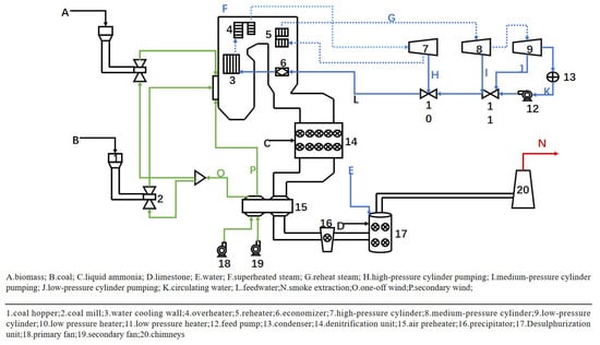
Figure 1.
Schematic diagram of direct mixed combustion biomass power generation system for coal-fired boiler.
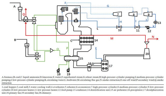
Figure 2.
Schematic diagram of flue gas waste heat recovery-type coal-fired boiler direct mixed combustion biomass power generation system.
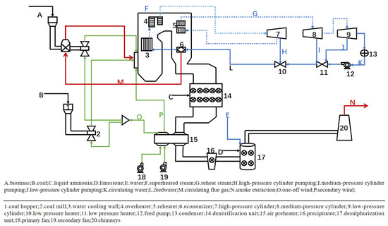
Figure 3.
Schematic diagram of flue gas recirculation-type coal-fired boiler direct mixing biomass power generation system.
2.2. Model Building
2.2.1. Assumptions
The basic assumptions of the model are given as follows:
- Ash is regarded as inert throughout the system and does not participate in the reaction;
- For any reaction in the system, the required reaction time is extremely short;
- The pulverized coal furnace operates in a steady-state manner, and the equipment parameters remain constant over time;
- There is no heat loss during any of the heat transfer processes.
2.2.2. Coal-Fired Boiler Fuel Parameters
Zambian sub-bituminous coal [30] was used for this simulation of a 660 MW pulverized coal boiler, and the industrial and elemental analyses of this coal are shown in Table 1 below.

Table 1.
Elemental, industrial and calorific analysis of coal species (dry basis).
A biomass fuel [31] was used for this simulation of a 660 MW pulverized coal boiler, and the industrial and elemental analyses of this fuel are shown in Table 2 below.

Table 2.
Elemental, industrial and calorific analysis of biomass (dry basis).
2.2.3. Model Description
Fuel conversion unit
The simplified flow simulation of the combustion process of pulverized coal in the boiler chamber is shown in Figure 4.

Figure 4.
Simplified flow chart of the combustion process in the boiler chamber.
The physical method selected for the combustion process of pulverized coal is the SRK (Soave-Redlich-Kwong) model. This model is based on the same equation of state as RK-SOAVE but improves the molar volume of the liquid using volumetric correction, similar to a cubic-type equation of state. The unit operation modules utilized in the combustion module include RYield, RGibbs, and Sep. In the entire simulation process, for the component part, the input component of coal is a non-conventional component and does not have corresponding physical parameters in the Aspen Plus software (V11) database. Therefore, it is necessary to input the relevant data of the coal into the simulation manually. We chose to calculate the enthalpy and density of the coal using the HCOALGEN and DCOALIGT calculation methods. The enthalpy and density of coal are calculated using the HCOALGEN and DCOALIGT calculation methods. The pulverized coal combustion process in the boiler is simulated using the RGibbs module. The Gibbs reactor calculates the system composition and phase distribution when both a chemical and phase equilibrium is reached based on the principle that the Gibbs free energy of a system tends to a minimum value. Without the need to know the reaction equations and chemical kinetics, the Gibbs reactor can be utilized to estimate the potential outcomes of the system in chemical and phase equilibrium. Since the RGibbs reactor does not recognize unconventional components, a stoichiometric reactor is required to convert each element in the coal (excluding ash) into a monomer. These monomers then enter the RGibbs free energy reactor. Here, the choice was made to utilize the RYield reactor to decompose the coal into pure components (C, H2, O2, S, H2O, Ash). The combustion products of the pulverized coal produced in the RGibbs reactor were then subjected to gas–solid separation using the Sep module, which separates the solid ash from the flue gases produced by the combustion.
Heat exchanger and turbine unit
The heat exchange system of the boiler primarily consists of the water-cooled wall, superheater, reheater, economizer, and air preheater. During the operation of the boiler, the flue gas transfers heat to water or steam through the heat transfer process, thereby enabling the efficient utilization of heat. Since the phase change process of water vapor is involved, the physical method of STEAMNBS is used in the simulation of the entire boiler process, and the NBS/NRC1984 model is selected for simulation. In the entire heat transfer process, we primarily use the following heat exchangers: Heater, HeaterX, and MHeatX. Specifically, the HeaterX module is applied to simulate the heat transfer process in water-cooled walls, superheaters, and economizers. The MHeatX module is utilized to simulate the heat transfer process in reheaters. Finally, the Heater module is used to simulate the heat exchange process in the condenser. The power generation system is primarily composed of a high-pressure cylinder, medium-pressure cylinder, low-pressure cylinder, condenser, and water pump. Superheated steam first enters the high-pressure cylinder to perform work. A portion of the high-pressure steam is diverted to the high-pressure heater to heat the circulating water. The reheated steam then enters the medium-pressure cylinder to perform work, and part of this steam is mixed with steam extracted from the low-pressure cylinder before entering the low-pressure heater. In the simulation process, the Compressor module is used to simulate all levels of pressure cylinders. The simulation of this module can be controlled by setting the outlet pressure of the steam. As the steam enters the turbine and expands to perform work, the conversion efficiency is set to 90%. The water pump is simulated using the Pump module, which can facilitate changes in material pressure and calculate the energy required for its operation. The pump efficiency is set to 0.9 during simulation. Both the high-pressure heater and low-pressure heater are simulated using the HeaterX module. The heat exchanger and turbine unit are shown in Figure 5.
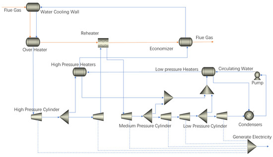
Figure 5.
Heat exchanger and turbine unit diagram.
Flue gas purification unit
The flue gas purification unit in the system primarily consists of denitrification and desulfurization equipment. This paper adopts Selective Catalytic Reduction (SCR) denitrification equipment, which utilizes NH3 as the reducing agent. The catalyst chosen for this process is V2O5-TiO2. The chemical reactions occurring in the denitrification process are as follows:
The simulation flowchart of the denitrification plant for the coal-fired direct mixing biomass power generation system is shown in Figure 6. The denitrification plant is simulated using the Rplug reactor and Mixer module, facilitating the mixing of liquid ammonia with the flue gas. The Rplug reactor is employed to simulate the chemical reaction between NH3 and NOX, achieving NOX removal. The simulation flowchart of the desulfurization equipment for the coal-fired direct mixed combustion biomass power generation system is depicted in Figure 7. Desulfurization equipment is simulated using the Sep2 separator. Following the separate entry of limewater and flue gas into the separator, limewater achieves adsorption desulfurization by undergoing acid-base neutralization reactions with SO2 present in the flue gas.

Figure 6.
Simulation flow chart of denitrification equipment.
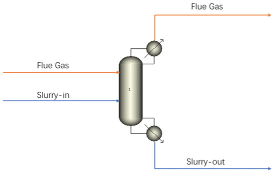
Figure 7.
Simulation flow chart of desulfurization equipment.
Modeling of direct mixing biomass power generation system for coal-fired boilers.
The entire system primarily comprises the following three units: the fuel conversion unit, the heat exchange and turbine unit, and the flue gas cleaning unit. The coal and biomass mixing unit is depicted in Figure 8, while the simulated flowchart of the direct mixing biomass power generation system in a coal-fired boiler is presented in Figure 9. Biomass and coal dust are converted into conventional monomers using the RYield reactor to facilitate the further combustion simulation process in the RGibbs free-energy reactor. The flue gas and ash produced by combustion are separated by the Sep module, which isolates the solid ash from the gaseous flue gas. The flue gas then enters the heat transfer module to transfer heat to water or steam. The steam enters the turbine power generation system, driving the turbine to rotate and generate power. The water vapor from the turbine’s low-pressure cylinder enters the condenser, where it condenses into liquid water. This water is then pressurized by the water pump and is heated through heat exchange with the high-temperature flue gas in the economizer, facilitating phase change. Simultaneously, the flue gas undergoes purification through denitrification and desulfurization equipment after heat exchange. Additionally, the combustion air required for the coal-fired boiler is preheated and warmed up by the air preheater before being supplied to the boiler for combustion.
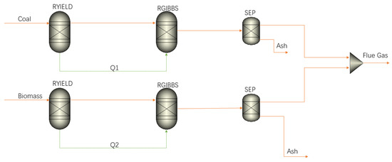
Figure 8.
Coal and biomass blending unit diagram.
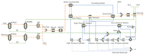
Figure 9.
Flow chart for the simulation of the biomass power generation system with direct mixing of coal-fired boilers.
Model of flue gas waste heat recovery-type coal-fired boiler direct mixing biomass power generation system.
The main difference between the flue gas waste heat recovery coal-fired boiler direct mixed combustion biomass power generation system and the conventional coal-fired boiler direct mixed combustion biomass power generation system in the simulation analysis is reflected in the method of flue gas treatment. The flue gas waste heat recovery-type coal-fired boiler direct mixed combustion biomass power generation system builds upon the traditional coal-fired boiler by recycling a portion of the tail exhaust gas. This type of system is characterized by the adoption of the partial flue gas pre-treatment of biomass fuel to reduce the moisture content of the biomass and narrow the difference between it and pulverized coal. This approach leads to more efficient energy utilization and lower pollutant emissions.
The simulation of the flue gas waste heat recovery-type coal-fired boiler direct mixed combustion biomass power generation system is shown in Figure 10. In this project, we employed flue gas waste heat recovery (FGHR) technology to utilize 10% of the flue gas treated by the air preheater for the pre-treatment of biomass fuel. This process aimed to reduce the moisture content of the biomass fuel. In this way, we were able to improve the combustion environment in the furnace and increase the combustion efficiency of the fuel. Specifically, in the Aspen Plus simulation software (V11), the introduction of 10% of the flue gas into the furnace combustion stage was achieved through the addition of the FSplit module after the air preheater. Subsequently, the flue gas was directed to the biomass drying pre-treatment process using the RStoic module. Through the RStoic module, the components were processed before entering the Sep module for gas–solid separation. After drying, the biomass fuel was mixed with pulverized coal and entered the furnace for combustion.
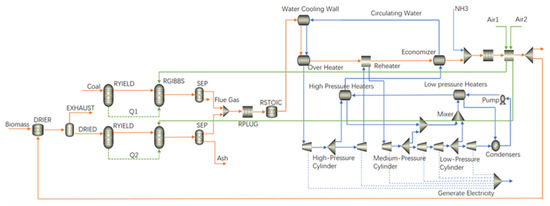
Figure 10.
Simulation of flue gas waste heat recovery-type coal-fired boiler direct mixing biomass power generation system.
Modeling of flue gas recirculation coal-fired boiler direct mixing biomass power generation system.
The flue gas recirculation-type coal-fired boiler direct mixed combustion biomass power generation system builds upon the flue gas waste heat recovery-type coal-fired boiler direct mixed combustion biomass power generation system by incorporating flue gas recirculation (FGR) technology. This system is characterized by extracting part of the high-temperature flue gas from the furnace for the pre-treatment of biomass fuel, in addition to retaining the flue gas waste heat recovery technology. The pre-treated flue gas and biomass volatiles are then fed back into the furnace for combustion, thus achieving flue gas recirculation.
The simulation of the flue gas recirculation-type coal-fired boiler direct mixing biomass power generation system is depicted in Figure 11. In this project, we employed flue gas recirculation technology, utilizing 10% of the flue gas from the coal economizer outlet for flue gas recirculation. This approach aimed to reduce the emission of pollutants in the flue gas. Specifically, in the Aspen Plus simulation software (V11), 10% of the flue gas was introduced into the post-drying stage of the biomass through the addition of the FSplit module after the coal economizer. The RYield reactor and the RGibbs reactor were then added to simulate the pyrolysis of the dried biomass via the high-temperature flue gas. The flue gas and volatile components from the RGibbs reactor were subsequently fed into the module, simulating furnace combustion, thereby achieving flue gas recirculation.
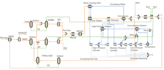
Figure 11.
Simulation of flue gas recirculation-type coal-fired boiler direct mixing biomass power generation system.
2.2.4. Model Validation
Through the simulation of the direct mixed combustion biomass power generation system of the coal-fired boiler, relevant parameters were derived and compared with the actual operation data of the power plant, as shown in Table 3 below. The table primarily included important parameters, such as power generation, as well as the temperature and pressure of each module. In the entire system simulation process, the proportion of biomass blending was set to 0%. By comparing the simulation parameters with the actual operating data, we could determine whether the deviations were within the allowable range. This comparison can help verify if the established coal-fired power plant power generation system can accurately simulate the actual operation of the coal-fired power plant.

Table 3.
Coal-fired boiler power generation system simulation data and plant operation data.
After comparison, it was found that the simulation data closely aligned with the actual operation data of the power plant, with only a small error observed, which was well within the permissible error range. As such, the model can be utilized to conduct simulations of the blending biomass power generation process.
2.3. Calculation Method
2.3.1. Mass Balance Calculation Method for Coupled Systems
The coal-fired-coupled biomass power generation system assumes negligible mass loss, and the system model is calculated based on overall mass conservation principles. In this paper, the effect of different mixing ratios (5%, 10%, 15%, and 20%) on each coupled system is investigated, where mixing ratios are defined as shown in Equation (1):
This model ensures that the boiler’s main steam parameters and reheat steam parameters remain constant for each operating condition. The mixing ratio is adjusted by varying the amount of coal and biomass fed into the system. The amount of coal and biomass fuel at different blending ratios is shown in Table 4.

Table 4.
Fuel quantity for different mixing ratios.
2.3.2. Heat Balance Calculation Method for Coupled Systems
The boiler combustion model is based on the Gibbs free energy principle, the overall energy conservation of the system under stable operating conditions, and the boiler heat balance equation is shown in Equation (2) [32]:
In the formula, is the mass flow rate of the fuel, kg/h; is the heat generation of the fuel, kJ/kg; is the steam flow rate, kg/h; is the enthalpy gain of the steam, kJ/kg; is the heat loss of the boiler, kJ/h; is the physical heat loss of the ash, kJ/h; is the loss of the exhaust smoke, kJ/h; and the boiler thermal efficiency is shown in Equation (3):
In the formula, and are coal consumption and biomass fuel consumption, kg/h, respectively; and are heat generation of coal and biomass fuel, kJ/kg, respectively; and are the superheated steam flow rate and reheated steam flow rate, kg/h, respectively; and are the enthalpy of superheated steam and reheated steam, kJ/kg, respectively; and and are feedwater enthalpy and reheat steam inlet enthalpy, kJ/kg, respectively.
3. Results and Analysis
3.1. Effect of Biomass Blending Ratio on Coal-Fired Boiler Power Generation System
The effects of various mixing ratios (5%, 10%, 15%, and 20%) on the power generation system of a 660 MW coal-fired boiler were analyzed, referencing the pure coal combustion condition at the boiler’s rated load.
In the absence of biomass mixing in the traditional coal-fired boiler, key operating parameters of the system are as follows: furnace combustion temperature of 2161 °C, system power generation of 659.2 MW, pre-denitrification NOX concentration of 348.13 mg/m3, water vapor mass fraction of 2.39%, and boiler thermal efficiency of 96.3%. As the biomass blending ratio increased, various system operating parameters underwent changes: the furnace combustion temperature decreased, circulating water volume decreased, power generation decreased, flue gas volume decreased, pre-denitrification NOX concentration decreased, SO2 volume decreased, water vapor mass fraction increased, and boiler thermal efficiency decreased. As depicted in Figure 12a, the rise in the proportion of biomass blending led to a decrease in both the furnace combustion temperature and power generation. This phenomenon arose from the higher moisture content in biomass fuel compared to coal. Upon its introduction into the furnace, the water content evaporates, thereby extracting heat and consequently lowering the furnace combustion temperature. In addition, the reduction in combustion temperature is also attributed to the high content of volatile substances in biomass. When biomass decomposes and releases volatiles, it forms porous charcoal that absorbs oxygen in the furnace chamber, further reducing the combustion temperature. Furthermore, the lower combustion temperatures can also be attributed to the low levels of fixed carbon in biomass, as fixed carbon serves as the primary combustible material [33]. Figure 12b illustrates that to maintain the consistent outlet temperature of the reheater in the system, the circulating water volume decreases accordingly. This reduction in circulating water volume results in decreased work performed by water vapor, consequently leading to a reduction in the system’s power generation. Simultaneously, biomass contains lower levels of nitrogen (N) and sulfur (S) elements compared to coal. The generation of nitrogen oxides (NOx) and sulfur dioxide (SO2) is directly correlated with the nitrogen and sulfur content of the fuel [34,35,36]. As depicted in Figure 13, the mass flow of sulfur dioxide (SO2) in the flue gas decreases, and the concentration of nitrogen oxides (NOx) decreases with the increasing proportion of biomass blending. This observation aligns with the findings reported by Jiang et al. [5]. Furthermore, the quantity of 35 nitrogen oxides (NOx) in generation and emissions is intricately linked to factors such as the fuel combustion mode, excess air coefficient, temperature, and other related parameters. The mechanism of nitrogen oxide (NOx) generation encompasses thermal, prompt, and fuel-type processes. Among these, the dominant mode in coal-fired power plants is fuel-type NOx, constituting approximately 80% of the total generation, followed by thermal-type NOx, accounting for up to about 20%. The contribution of prompt-type NOx generation is notably smaller. Consequently, the reduction in furnace combustion temperature primarily affects the generation of fuel-type and thermal-type NOx, subsequently influencing NOx concentration.
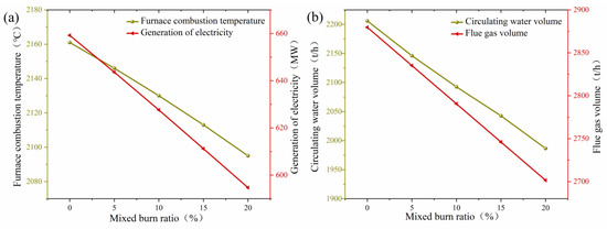
Figure 12.
(a) Effect of doping ratio on furnace combustion temperature and power generation; (b) Effect of doping ratio on circulating water volume and flue gas volume.
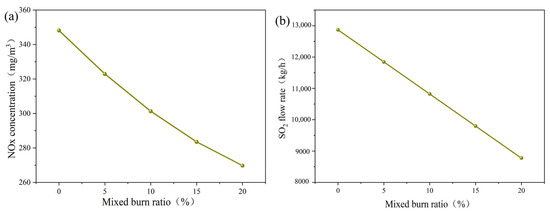
Figure 13.
(a) Effect of doping ratio on NOX concentration. (b) Effect of doping ratio on SO2 mass flow rate.
As illustrated in Figure 14, compared to the thermal efficiency of pure coal-fired boilers used as a baseline, the thermal efficiency of the boiler decreases following the addition of biomass blending. Furthermore, the boiler’s thermal efficiency demonstrates a declining trend with increasing proportions of biomass blending. The reduction in boiler thermal efficiency can be primarily attributed to an increase in exhaust smoke loss, as indicated by the boiler heat balance equation. This rise in smoke loss is a consequence of several factors associated with biomass blending. Firstly, biomass possesses a lower calorific value compared to coal. Additionally, biomass tends to have higher discounted moisture content and a higher H/C value. Consequently, following the blending and combustion of biomass, the flue gas contains a higher concentration of water vapor. Moreover, as the blending and burning ratio increases, so does the water vapor content in the flue gas. This trend is evident in the data, with the mass fraction of water vapor in the flue gas increasing from 2.39% to 3.62% across blending ratios of 0%, 5%, 10%, 15%, and 20%. The presence of water vapor leads to the absorption of heat, thereby elevating boiler smoke loss and subsequently reducing thermal efficiency.
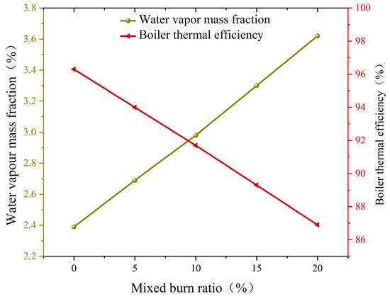
Figure 14.
Effect of blending ratio on water vapor mass fraction and boiler thermal efficiency.
3.2. Impact of Flue Gas Waste Heat Recovery on Coal-Fired Boiler Power Generation Systems
In this study, flue gas waste heat recovery (FGHR) technology was employed to extract a portion of the low-temperature flue gas at the tail end for pre-treating biomass drying. Using the conventional coal-fired boiler power generation system as a benchmark, this study analyzed the impact of extracting 10% of the exhaust flue gas from the tail for biomass pre-treatment on the power generation system under varying blending ratios (5%, 10%, 15%, and 20%).
The introduction of flue gas waste heat recovery technology resulted in changes to the operating parameters of the system under various biomass blending ratios. Firstly, as depicted in Figure 15a, the combustion temperature of the furnace chamber increased to varying degrees under different blending ratios. In particular, in the 0% to 15% blending ratios, the combustion temperature increased progressively with the blending ratio, peaking at the 15% blending ratio. However, the increment of combustion temperature was reduced at a 20% blending ratio. This increase in combustion temperature is attributed to the utilization of flue gas waste heat. The residual heat in the flue gas has a drying effect on the biomass, thereby enhancing its calorific value. This effect is advantageous for the blending and combustion of coal and biomass [26]. Based on the observations from Figure 15b and Figure 16, the implementation of flue gas waste heat recovery technology leads to an increase in the system’s power generation and boiler thermal efficiency. The incremental gains in power generation and boiler thermal efficiency gradually rise with higher proportions of biomass blending. Conversely, as indicated in Figure 15c, the mass fraction of water vapor in the flue gas decreases with the adoption of this technology, and this decrease intensifies with higher blending proportions. This effect is attributed to a portion of the extracted tail flue gas being introduced into the biomass pre-treatment equipment, where it exerts a drying effect on the biomass. The tail flue gas absorbs moisture from the biomass fuel, thereby reducing the mass fraction of water vapor in the flue gas. Consequently, less heat is taken away by the water vapor, leading to a reduction in heat loss from exhaust smoke. This reduction in heat loss contributes to increased boiler efficiency. Furthermore, the nature of the biomass after drying becomes more akin to coal, thereby altering its combustion performance. Moreover, the dried biomass exhibits combustion characteristics closer to coal, resulting in improved combustion performance. Consequently, the furnace combustion temperature increases. To maintain a consistent steam outlet temperature from the reheater, the circulating water volume is increased, leading to an increase in power generation.
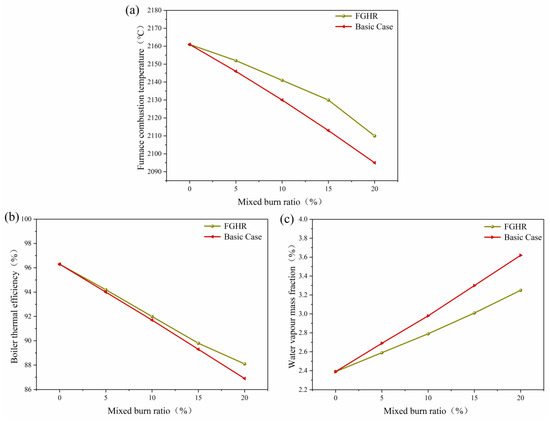
Figure 15.
(a) Effect of flue gas waste heat recovery on furnace combustion temperature. (b) Effect of flue gas waste heat recovery on boiler thermal efficiency. (c) Effect of flue gas waste heat recovery on water vapor mass fraction in flue gas.
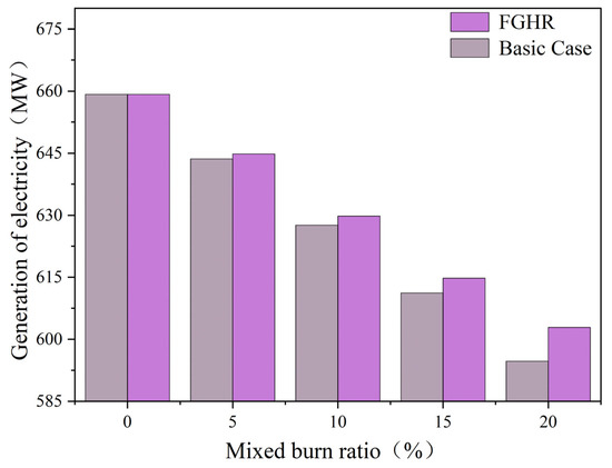
Figure 16.
Impact of flue gas waste heat recovery on power generation.
3.3. Impact of Flue Gas Recirculation on Power Generation Systems in Coal-Fired Boilers
The current application of flue gas recirculation (FGR) technology in coal-fired boilers holds significant importance, primarily achieved by reintroducing a portion of the flue gas back into the boiler for combustion. This paper specifically concentrates on utilizing a segment of the flue gas within the furnace chamber to process dried biomass through flue gas extraction. Using the conventional coal-fired boiler power generation system as a reference, this study analyzes the effects of extracting 10% of the exhaust flue gas from the tail end and 10% of the circulating flue gas in the furnace for biomass pre-treatment on the power generation system. This analysis is conducted across various blending ratios (5%, 10%, 15%, and 20%).
The circulating flue gas initially treats the biomass, enhancing its calorific value and grindability, thus enabling better co-firing with coal [26,27,28]. An increased proportion of blended biomass theoretically reduces net carbon emissions. Additionally, pre-treated biomass reduces transportation costs and improves corrosion resistance [37,38]. Subsequently, the recirculated flue gas is reintroduced into the furnace chamber for re-combustion. The introduction of flue gas recirculation alters the operational parameters of the coal-fired boiler power generation system. Figure 17 illustrates the impact of flue gas recirculation technology on the system at various mixing ratios. It is evident that the introduction of flue gas recirculation technology markedly decreases the furnace combustion temperature and NOx concentration compared to the conventional coal-fired boiler baseline. This finding aligns with the observations made by Liu et al. [25]. As the biomass blending ratio increases, the reduction in NOx concentration becomes more pronounced. Specifically, at a blending ratio of 5%, there is a concentration reduction of 50.27 mg/m3. This reduction increases to 64.4 mg/m3 at a blending ratio of 10%, further increases to 100.8 mg/m3 at 15% blending and reaches 160.44 mg/m3 at 20% blending. This phenomenon occurs because the already combusted flue gas re-enters the combustion chamber after treating the biomass. This re-entry reduces the oxygen concentration in the mixture, thereby lowering the combustion temperature in the furnace chamber. According to the mechanism of NOx generation, it is understood that oxygen-deficient conditions, along with lower temperatures, have a greater impact on reducing the generation of NOx. Therefore, the addition of flue gas recirculation leads to lower NOx concentrations, with a more significant impact observed as the amount of biomass blending increases. The impact of flue gas recirculation on the operating parameters is more pronounced with higher biomass blending ratios.
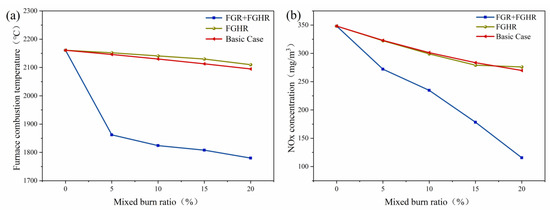
Figure 17.
(a) Effect of flue gas recirculation on furnace combustion temperature. (b) Effect of flue gas recirculation on NOx concentration.
A study on the effect of the flue gas recirculation rate on the power generation system of a coal-fired boiler was conducted by varying the amount of recycled flue gas extracted. The impact of flue gas recirculation technology on the boiler power generation system was analyzed at different flue gas recirculation rates (2.5%, 5%, 7.5%, 10%), using the boiler power generation system with 15% blending and 10% flue gas waste heat recovery as a benchmark.
Figure 18 illustrates the impact of the flue gas recirculation rate on the system. It is evident that as the flue gas recirculation rate increases, the combustion temperature in the furnace chamber significantly decreases while the amount of flue gas remains constant. The NOx concentration in the flue gas gradually decreases from 279.1 mg/m3 to 178.3 mg/m3. The recirculated flue gas, characterized by lower oxygen content and temperature, re-enters the furnace chamber, thereby affecting the original combustion conditions of the boiler. This effect reduces combustion efficiency in the chamber, consequently lowering the furnace combustion temperature. The reduction in temperature and oxygen concentration leads to a decrease in NOx generation. As the rate of flue gas recirculation increases, this impact becomes more pronounced. Therefore, a higher rate of circulating flue gas results in a lower furnace combustion temperature and a lower concentration of NOx in the flue gas.
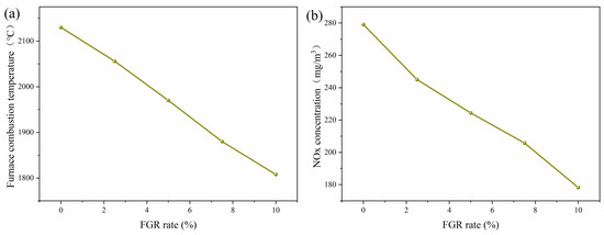
Figure 18.
(a) Effect of flue gas recirculation rate on furnace combustion temperature. (b) Effect of flue gas recirculation rate on NOx concentration.
4. Conclusions
To establish the coal-fired boiler direct-mixed biomass power generation system, Aspen Plus software (V11) was initially utilized to construct modules for pulverized coal combustion, heat exchange, power generation, as well as desulfurization and denitrification, tailored to emulate real-world processes. Subsequently, models were developed for the flue gas waste heat recovery coal-fired boiler direct-mixed biomass power generation system and the flue gas recirculation coal-fired boiler direct-mixed biomass power generation system based on this initial model. These models facilitated an investigation into the influence of the biomass blending ratio, flue gas waste heat recovery technology, flue gas recirculation technology, and flue gas recirculation rate on various system parameters, including furnace combustion temperature, power generation capacity, and flue gas composition (comprising water vapor mass fraction, SO2 mass flow rate, and NOx concentration).
These findings indicate that with an increase in the percentage of biomass blending, there is a decrease in furnace combustion temperature, power generation, and boiler efficiency. Conversely, both NOx and SO2 content in the flue gas decrease while the water vapor mass fraction increases.
Integrating flue gas waste heat recovery leads to an elevated furnace combustion temperature, power generation, and boiler efficiency, accompanied by a reduction in the water vapor mass fraction in the flue gas. Notably, higher blending ratios exhibit greater increments in power generation and boiler efficiency alongside larger decreases in the water vapor fraction. For instance, at a 20% blending ratio, power generation and boiler efficiency increased by 8.2 MW and 1.2%, respectively, with a corresponding decrease in the water vapor mass fraction by 0.37%.
Furthermore, flue gas recirculation induces a reduction in the furnace combustion temperature and NOx concentration in the flue gas. The magnitude of NOx concentration reduction correlates with the blending ratio, with larger reductions observed at higher blending ratios. Specifically, for a 5% blending ratio, the reduction in NOx concentration is 50.27 mg/m3, increasing to 160.44 mg/m3 for a 20% blending ratio. Moreover, augmenting the flue gas recirculation rate exacerbates a decrease in combustion temperature and NOx concentration in the flue gas. In the case of a 15% blending ratio, the reduction in NOx concentration amplifies as the recirculation rate escalates, with NOx concentrations ranging from 279.1 mg/m3 at a 0% recirculation rate to 178.3 mg/m3 at a 10% recirculation rate.
Author Contributions
Methodology, N.G.; Software, F.R.; Formal analysis, N.G.; Data curation, F.R.; Writing—original draft, C.S.; Writing—review & editing, X.R. All authors have read and agreed to the published version of the manuscript.
Funding
This research received no external funding.
Data Availability Statement
The original contributions presented in the study are included in the article, further inquiries can be directed to the corresponding author.
Acknowledgments
The authors acknowledge the support of the National Key Research and Development Program of China (2022YFB4202005).
Conflicts of Interest
The authors declare no conflict of interest.
References
- Liu, L.; Memon, M.Z.; Xie, Y.; Gao, S.; Guo, Y.; Dong, J.; Gao, Y.; Li, A.; Ji, G. Recent advances of research in coal and biomass co-firing for electricity and heat generation. Circ. Econ. 2023, 2, 100063. [Google Scholar] [CrossRef]
- Wang, S.R.; Dai, G.X.; Yang, H.P.; Luo, Z.Y. Lignocellulosic biomass pyrolysis mechanism: A state-of-the-art review. Prog. Energy Combust. Sci. 2017, 62, 33–86. [Google Scholar] [CrossRef]
- Lu, H.; Gong, Y.; Areeprasert, C.; Ding, L.; Guo, Q.; Chen, W.H.; Yu, G. Integration of Biomass Torrefaction and Gasification based on Biomass Classification: A Review. Energy Technol. 2021, 9, 2001108. [Google Scholar] [CrossRef]
- Gungor, A. Simulation of co-firing coal and biomass in circulating fluidized beds. Energy Convers. Manag. 2013, 65, 574–579. [Google Scholar] [CrossRef]
- Jiang, Y.; Mori, T.; Naganuma, H.; Ninomiya, Y. Effect of the optimal combination of bituminous coal with high biomass content on particulate matter (PM) emissions during co-firing. Fuel 2022, 316, 123244. [Google Scholar] [CrossRef]
- Zhang, X.; Li, K.; Zhang, C.; Wang, A. Performance analysis of biomass gasification coupled with a coal-fired boiler system at various loads. Waste Manag. 2020, 105, 84–91. [Google Scholar] [CrossRef]
- Jin, H.; Luo, K.; Stein, O.; Watanabe, H.; Ku, X. Coal and Biomass Combustion. J. Combust. 2018, 2018, 9654923. [Google Scholar] [CrossRef]
- Muthuraman, M.; Namioka, T.; Yoshikawa, K. A comparison of co-combustion characteristics of coal with wood and hydrothermally treated municipal solid waste. Bioresour. Technol. 2010, 101, 2477–2482. [Google Scholar] [CrossRef]
- Vamvuka, D.; Kakaras, E.; Kastanaki, E.; Grammelis, P. Pyrolysis characteristics and kinetics of biomass residuals mixtures with lignite. Fuel 2003, 82, 1949–1960. [Google Scholar] [CrossRef]
- Liu, Q.; Zhong, W.; Tang, R.; Yu, H.; Gu, J.; Zhou, G.; Yu, A. Experimental tests on co-firing coal and biomass waste fuels in a fluidised bed under oxy-fuel combustion. Fuel 2021, 286, 119312. [Google Scholar] [CrossRef]
- Priyanto, D.E.; Matsunaga, Y.; Ueno, S.; Kasai, H.; Tanoue, T.; Mae, K.; Fukushima, H. Co-firing high ratio of woody biomass with coal in a 150-MW class pulverized coal boiler: Properties of the initial deposits and their effect on tube corrosion. Fuel 2017, 208, 714–721. [Google Scholar] [CrossRef]
- Li, J.; Wang, Z.; Ma, C. Numerical simulation and combustion analysis of coal and biomass co-combustion. MATEC Web Conf. 2022, 355, 02013. [Google Scholar] [CrossRef]
- Mehmood, S.; Reddy, B.V.; Rosen, M.A. Exergy Analysis of a Biomass Co-Firing Based Pulverized Coal Power Generation System. Int. J. Green Energy 2015, 12, 461–478. [Google Scholar] [CrossRef]
- Mehmood, S.; Reddy, B.V.; Rosen, M.A. Energy Analysis of a Biomass Co-firing Based Pulverized Coal Power Generation System. Sustainability 2012, 4, 462–490. [Google Scholar] [CrossRef]
- Huang, Y.; Wan, Y.; Liu, S.; Zhang, Y.; Ma, H.; Zhang, S.; Zhou, J. A Downdraft Fixed-Bed Biomass Gasification System with Integrated Products of Electricity, Heat, and Biochar: The Key Features and Initial Commercial Performance. Energies 2019, 12, 2979. [Google Scholar] [CrossRef]
- Zhang, S.; Chen, Z.; Zhang, H.; Wang, Y.; Xu, X.; Cheng, L.; Zhang, Y. The catalytic reforming of tar from pyrolysis and gasification of brown coal: Effects of parental carbon materials on the performance of char catalysts. Fuel Process. Technol. 2018, 174, 142–148. [Google Scholar] [CrossRef]
- Xu, Y.; Yang, K.; Zhou, J.; Zhao, G. Coal-Biomass Co-Firing Power Generation Technology: Current Status, Challenges and Policy Implications. Sustainability 2020, 12, 3692. [Google Scholar] [CrossRef]
- Basu, P.; Butler, J.; Leon, M.A. Biomass co-firing options on the emission reduction and electricity generation costs in coal-fired power plants. Renew. Energy 2011, 36, 282–288. [Google Scholar] [CrossRef]
- Jeswani, H.K.; Gujba, H.; Azapagic, A. Assessing Options for Electricity Generation from Biomass on a Life Cycle Basis: Environmental and Economic Evaluation. Waste Biomass Valorization 2011, 2, 33–42. [Google Scholar] [CrossRef]
- Agbor, E.; Zhang, X.; Kumar, A. A review of biomass co-firing in North America. Renew. Sustain. Energy Rev. 2014, 40, 930–943. [Google Scholar] [CrossRef]
- Xiaorui, L.; Xudong, Y.; Guilin, X.; Yiming, Y. NO emission characteristic during fluidized combustion of biomass with limestone addition. Fuel 2021, 291, 120264. [Google Scholar] [CrossRef]
- Lyu, S.; Cao, T.; Zhang, L.; Liu, J.; Li, G.; Ren, X. Assessment of low-rank coal and biomass co-pyrolysis system coupled with gasification. Int. J. Energy Res. 2019, 44, 2652–2664. [Google Scholar] [CrossRef]
- Liao, W.; Zhang, X.; Ke, H.; Zhang, S.; Shao, J.; Yang, H.; Wang, X.; Chen, H. The techno-economic-environmental analysis of a pilot-scale positive pressure biomass gasification coupled with coal-fired power generation system. J. Clean. Prod. 2023, 402, 136793. [Google Scholar] [CrossRef]
- Ye, B.; Zhang, R.; Cao, J.; Shi, B.; Zhou, X.; Liu, D. Thermodynamic and economic analyses of a coal and biomass indirect coupling power generation system. Front. Energy 2020, 14, 590–606. [Google Scholar] [CrossRef]
- Liu, S.; Kuang, M.; Qi, S.; Zhao, X. Strengthening low-NOx combustion with flue gas recirculation in a 600-MWe down-fired furnace. Asia-Pac. J. Chem. Eng. 2022, 17, e2831. [Google Scholar] [CrossRef]
- Howell, A.; Beagle, E.; Belmont, E. Torrefaction of Healthy and Beetle Kill Pine and Co-Combustion with Sub-Bituminous Coal. J. Energy Resour. Technol. Trans. ASME 2018, 140, 042002. [Google Scholar] [CrossRef]
- Waheed, M.A.; Akogun, O.A. Quality enhancement of fuel briquette from cornhusk and cassava peel blends for co-firing in coal thermal plant. Int. J. Energy Res. 2021, 45, 1867–1878. [Google Scholar] [CrossRef]
- Sher, F.; Yaqoob, A.; Saeed, F.; Zhang, S.; Jahan, Z.; Klemeš, J.J. Torrefied biomass fuels as a renewable alternative to coal in co-firing for power generation. Energy 2020, 209, 118444. [Google Scholar] [CrossRef]
- Kopczyński, M.; Lasek, J.A.; Iluk, A.; Zuwała, J. The co-combustion of hard coal with raw and torrefied biomasses (willow (Salix viminalis), olive oil residue and waste wood from furniture manufacturing). Energy 2017, 140, 1316–1325. [Google Scholar] [CrossRef]
- Chelgani, S.C. Investigating the occurrences of valuable trace elements in African coals as potential byproducts of coal and coal combustion products. J. Afr. Earth Sci. 2019, 150, 131–135. [Google Scholar] [CrossRef]
- Li, L.; Yu, C.; Huang, F.; Bai, J.; Fang, M.; Luo, Z. Study on the Deposits Derived from a Biomass Circulating Fluidized-Bed Boiler. Energy Fuels 2012, 26, 6008–6014. [Google Scholar] [CrossRef]
- Cai, Q.; Wu, X.; Huang, Y.; Wang, X. The research on the influence of boiler operating parameters on thermal efficiency. IOP Conf. Ser. Earth Environ. Sci. 2020, 585, 012113. [Google Scholar] [CrossRef]
- Liu, H.; Han, K.; Liu, M.; Niu, S.; Lu, C. A Thermogravimetric Analysis of Co-combustion Characteristics of Biomass and Coal in an O2/CO2 Atmosphere. Energy Sources Part A Recovery Util. Environ. Eff. 2015, 37, 2451–2457. [Google Scholar]
- Munir, S.; Daood, S.S.; Nimmo, W.; Cunliffe, A.M.; Gibbs, B.M. Thermal analysis and devolatilization kinetics of cotton stalk, sugar cane bagasse and shea meal under nitrogen and air atmospheres. Bioresour. Technol. 2009, 100, 1413–1418. [Google Scholar] [CrossRef]
- Tao, G.; Lestander, T.A.; Geladi, P.; Xiong, S. Biomass properties in association with plant species and assortments I: A synthesis based on literature data of energy properties. Renew. Sustain. Energy Rev. 2012, 16, 3481–3506. [Google Scholar] [CrossRef]
- Yang, X.; Luo, Z.; Liu, X.; Yu, C.; Li, Y.; Ma, Y. Experimental and numerical investigation of the combustion characteristics and NO emission behaviour during the co-combustion of biomass and coal. Fuel 2021, 287, 119383. [Google Scholar] [CrossRef]
- Ren, X.; Sun, R.; Meng, X.; Vorobiev, N.; Schiemann, M.; Levendis, Y.A. Carbon, sulfur and nitrogen oxide emissions from combustion of pulverized raw and torrefied biomass. Fuel 2017, 188, 310–323. [Google Scholar] [CrossRef]
- Rokni, E.; Ren, X.; Panahi, A.; Levendis, Y.A. Emissions of SO2, NOx, CO2, and HCl from Co-firing of coals with raw and torrefied biomass fuels. Fuel 2018, 211, 363–374. [Google Scholar] [CrossRef]
Disclaimer/Publisher’s Note: The statements, opinions and data contained in all publications are solely those of the individual author(s) and contributor(s) and not of MDPI and/or the editor(s). MDPI and/or the editor(s) disclaim responsibility for any injury to people or property resulting from any ideas, methods, instructions or products referred to in the content. |
© 2024 by the authors. Licensee MDPI, Basel, Switzerland. This article is an open access article distributed under the terms and conditions of the Creative Commons Attribution (CC BY) license (https://creativecommons.org/licenses/by/4.0/).