Abstract
Due to high greenhouse gas emissions, countries worldwide are stepping up their emission reduction efforts, and the global demand for new, carbon-free fuels is growing. Ammonia (NH3) fuels are popular due to their high production volume, high energy efficiency, ease of storage and transportation, and increased application in power equipment. However, their physical characteristics (e.g., unstable combustion, slow flame speed, and difficult ignition) limit their use in power equipment. Based on the structural properties of the power equipment, NH3 fuel application and emissions characteristics were analyzed in detail. Combustion of NH3 fuels and reduction measures for NOx emissions (spark plug ignition, compression ignition, and gas turbines) were analyzed from various aspects of operating conditions (e.g., mixed fuel, fuel-to-exhaust ratio, and equivalence ratio), structure and strategy (e.g., number of spark plugs, compression ratio (CR), fuel injection, and ignition mode), and auxiliary combustion techniques (e.g., preheating, humidification, exhaust gas recirculation, and secondary air supply). The performance of various NH3 fuel cell (FC) types was analyzed, with a focus on the maximum power achievable for different electrolyte systems. Additionally, the application and NOx emissions of indirect NH3 FCs were evaluated under flame and catalytic combustion conditions. The system efficiency of providing heat sources by burning pure NH3, anode tail gas, and NH3 decomposition gas was also compared. Based on a comprehensive literature review, the key factors influencing the performance and emissions of NH3-powered equipment were identified. The challenges and limitations of NH3-powered equipment were summarized, and potential strategies for improving efficiency and reducing emissions were proposed. These findings provide valuable insights for the future development and application of NH3 FCs.
1. Introduction
The issue of global warming, which is brought about by the excessive release of greenhouse gases, has become a pressing concern that humans must urgently address [1,2,3]. Reducing emissions is the primary means of achieving the “two-carbon” goals [4]. Controlling global warming at 1.5 °C instead of 2 °C would bring significant advantages to humanity, encompassing aspects such as sea level rise, meteorological disaster, water scarcity, permafrost thawing, and more [5]. The largest obstacle we face in our generation is climate change. To meet the temperature criterion of 1.5 °C laid down by the Intergovernmental Panel on Climate Change and reduce global greenhouse gas emissions, it is imperative to identify technically reliable, commercially significant, environmentally friendly, and safe solutions [6,7]. The global response to greenhouse gases is shown in Figure 1.

Figure 1.
Global action to reduce emissions.
With the pressing need to address climate change, vigorously developing renewable and carbon-free energy sources has become paramount [1,2,3]. Energy carriers are crucial in balancing intermittent renewable energy production with ever-increasing demand [8,9]. For the mass transportation of hydrogen-containing fuels, liquefied forms of energy storage are preferred [10]. Liquid fuels, including liquid hydrogen or hydrogen-containing carriers such as ammonia (NH3), have gained traction in various applications [11,12]. Safe, reliable, and easily transportable energy is essential for achieving the “two-carbon” goals [13,14]. However, the lack of large-scale, reliable infrastructure hampers the efficient storage and transportation of hydrogen energy [15,16]. In contrast to hydrogen, NH3 energy boasts a well-established global infrastructure, a complete industrial chain for production, transportation, storage, and terminal applications, and favorable physical properties such as higher energy density [17]. These advantages position NH3 as a promising alternative to fossil fuels, with green NH3 production technologies further enhancing its appeal as a sustainable decarbonization fuel [18,19,20]. Moreover, NH3 exhibits superior safety compared to methane (CH4), hydrogen, liquefied petroleum gas, methanol, and gasoline [17,21]. As evident from Table 1, NH3 is emerging as a frontrunner for future renewable energy solutions [17,21,22,23]. Its cost-effectiveness, low carbon emissions, high efficiency, and safety make it a compelling choice to replace carbon-based energy sources. However, as NH3 energy gains recognition, it is crucial to closely monitor pollutant emissions and the far-reaching impacts of the nitrogen cycle on the global environment throughout NH3’s life cycle, from nitrogen synthesis to final decomposition [24,25,26]. NH3 fuel applications and emissions as shown in Figure 2.

Table 1.
Physical property parameters of fuel [27].
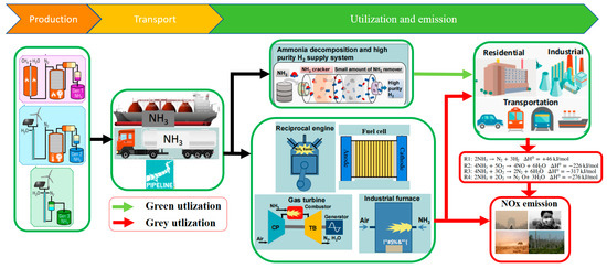
Figure 2.
NH3 fuel applications and emissions [21,26].
Utilizing alternative energy sources through minor modifications in carbonaceous energy-powered equipment presents a rapid and cost-effective approach to developing NH3 energy [28]. However, NH3 combustion faces challenges such as ignition difficulties, slow flame propagation, and instability. Additionally, a low heat release rate (HRR) and high NOx emissions hinder the widespread use of NH3 in power equipment. NH3 also serves as an effective hydrogen carrier, enabling the decomposition of NH3 to generate hydrogen as a green energy source. Simultaneously, NH3 fuel can participate in FC reactions to produce a stream of electrons, generating electricity [8]. However, NH3’s weak reaction kinetics and slow chemical reaction rate limit its power output and hinder its broader application in fuel cells (FCs) [17]. Mixing NH3 with fuels with higher reactivity can effectively improve its combustion rate. Other measures, such as structural adjustments, strategic optimization, and auxiliary combustion technologies, have also yielded promising results in enhancing NH3 combustion [17].
To advance the application of NH3 power equipment, researchers have delved into NH3 combustion, considering the advantages and limitations of green NH3 synthesis. Studies have shown that pure NH3 combustion presents challenges that must be addressed. Olabi et al. [20] explored the potential of NH3 fuel in the energy sector and identified technical, economic, environmental, and regulatory hurdles that need to be overcome. Vries et al. [18] examined the current research status of various NH3 applications as a green decarbonization fuel for heating, thermal power generation, and power equipment. Berwal et al. [19] reviewed the synthesis, chemical kinetics, and practical applications of NH3 as a future combustion fuel, drawing insights from the combustion mechanism. Zamfirescu et al. [11] discussed and analyzed potential methods for using NH3 as a sustainable fuel in FCs, evaluating efficiency and availability parameters based on the chemical reaction mechanism.
For power equipment that relies on thermal energy as the power source, the combustion chamber structure and combustion characteristics vary among different types of equipment, leading to distinct physical parameter requirements and pollutant emissions profiles for fuel. Similarly, for FCs that generate electricity through chemical reactions, each type of FC exhibits unique chemical reactions and optimal reaction temperatures, resulting in different pollutant emissions and corresponding mitigation strategies. Considering the diverse structures and operating principles of power equipment, this paper provides a comprehensive overview of NH3 utilization as a decarbonization fuel and the associated pollutant emission reduction measures. It categorizes the output performance and pollutant emission characteristics of different power equipment, summarizes the challenges faced by NH3 application, and presents an outlook on the future of NH3 as a power source. The following sections delve into the NH3 fuel application and NOx emission characteristics of spark plug ignition (SI) engines, compression ignition (CI) engines, and gas turbines (GTs) from various aspects of operating conditions (e.g., mixed fuel, fuel-to-exhaust ratio, and equivalence ratio), structure and strategy (e.g., number of spark plugs, compression ratio (CR), fuel injection, and ignition mode), and auxiliary combustion techniques (e.g., preheating, humidification, exhaust gas recirculation, and secondary air supply). Meanwhile, the paper also reviews the output performance of different ammonia fuel cells under chemical combustion and flame combustion, especially the system efficiency and emission of indirect ammonia fuel cells based on supply from different heat sources (burning NH3 combustion, anode tail gas combustion, and NH3 decomposition gas). These findings will provide valuable insights for the development and application of NH3 FCs.
2. Ammonia Used in Spark Ignition Engines
2.1. Mixing Fuels with Strong Activity
In SI engines, the fuel is compressed to the appropriate pressure and temperature for ignition through piston movement. High-energy spark plug injection ignites the fuel, causing it to expand and perform work, as illustrated in Figure 3. As a result, alternative fuels must have strong anti-knock properties and readily form a uniform mixture with air. NH3 possesses excellent anti-knock properties, making it a promising carbon-free green energy source for SI engines. However, the development of NH3 fuel in SI engines is hindered by its unfavorable physical properties. Several researchers, including Cornelius et al. [28], Starkman et al. [29,30], Cornelius et al. [22], Liu et al. [31], and Grannell et al. [32], have experimentally investigated NH3 as a fuel for SI engines. Their findings indicate that pure NH3 faces challenges such as inefficient flame propagation, difficult ignition, and unstable combustion, making it challenging to operate effectively in SI engines. Furthermore, NOx and unburned NH3 emissions are relatively high when using pure NH3.
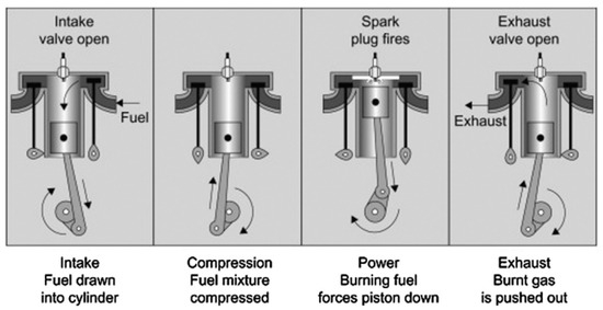
Figure 3.
Typical 4-stroke SI internal combustion engine [11].
2.1.1. Combustion and Emission of NH3/Gasoline SI Engines
Gaseous ammonia is pre-mixed with high-pressure ejected gasoline for 5 h, then mixed with a certain amount of air and injected into the cylinder through a direct ejector [33]. Supplementing NH3 with reactive fuels is considered a crucial step in improving combustion stability and reducing the coefficient of variation (COV) of NH3 combustion flame cycles [34]. For example, the laminar flame speed of NH3 is limited to only 0.07 m/s [35], whereas that of gasoline is nearly 0.58 m/s. Therefore, incorporating gasoline into the mixture enhances flame propagation within the combustion chamber [25]. As mentioned earlier, SI engines rely on high-energy spark plug injection after compression to ignite the fuel. Consequently, the fuel should not self-ignite during the compression process, as this can lead to knocking and reduced SI output performance. NH3’s anti-knock properties enable NH3/gasoline SI engines to operate at higher pressures, resulting in improved work efficiency [33]. While a high CR can significantly enhance the combustion characteristics of NH3 fuel, a CR of 12:1 or higher is not recommended due to the intersection of the minimum advance of the optimal torque detonation limit and rough limit crossover [36]. The schematic diagram of the ammonia and gasoline mixed-combustion test process as shown in Figure 4. On the other hand, mixing NH3 with gasoline requires an increase in the ignition advance angle of the SI engine. A significant portion of the spark advance adjustment occurs when NH3 contributes approximately 10% of the overall fuel energy input, but further increases in NH3 content do not have any noticeable impact on flame speed [37].
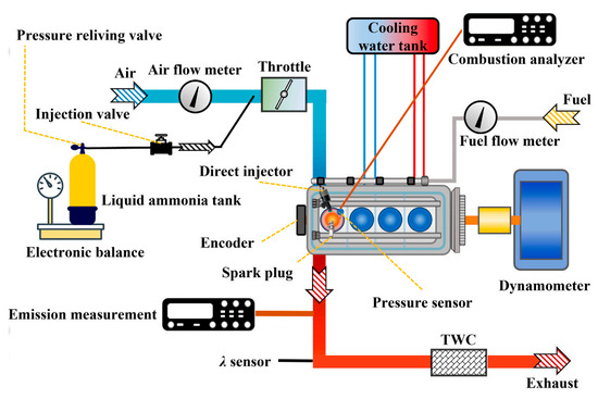
Figure 4.
The schematic diagram of the ammonia and gasoline mixed-combustion test process [36].
Blending NH3 leads to a deterioration in NOx emissions due to fuel–NOx formation. However, the sensitivity of NOx emissions to the NH3 blending ratio is generally moderate, and the trend of NOx emissions with the ignition advance angle is opposite to that of pure gasoline, indicating that fuel–NOx emission is strongly correlated with in-cylinder pressure [37]. Under high CR test conditions, Westlye et al. [38] found that NOx was primarily produced during gap volume combustion and observed that NO emission levels were similar to those observed in gasoline measurements when the excess air coefficient (λ) is 1, mainly due to a lower flame temperature. The simulation involving the mechanism model revealed that the reaction between NH2 and NO2, as well as NH and NO, significantly influences the magnitude of this reaction, which is strongly influenced by the timing of ignition.
2.1.2. Combustion and Emission of NH3/CH4 SI Engines
CH4, with its higher auto-ignition temperature and ability to form a more uniform mixture with air, is widely used in gasoline SI engines, requiring only minor modifications to the existing structure to meet operational requirements [27,28]. The physical properties of CH4, such as density at room temperature, adiabatic combustion temperature, volumetric energy density, and octane number, closely resemble those of NH3. Additionally, the laminar burning velocity of CH4 combustion is over five times greater than that of NH3 as a fuel. Therefore, combining NH3 and CH4 in combustion holds promising prospects for enhancing the combustion properties of NH3. Compared with the pure NG engine, increasing XNH3 decreased the peak pressure (Pmax) and HRR while increasing the best thermal efficiency (BTE) by 1%. NOx emissions, originating from NH3 at 873 K, initially increased with increasing XNH3 but then decreased [39]. The schematic diagram of the ammonia and natural gas mixed-combustion test process as shown in Figure 5.
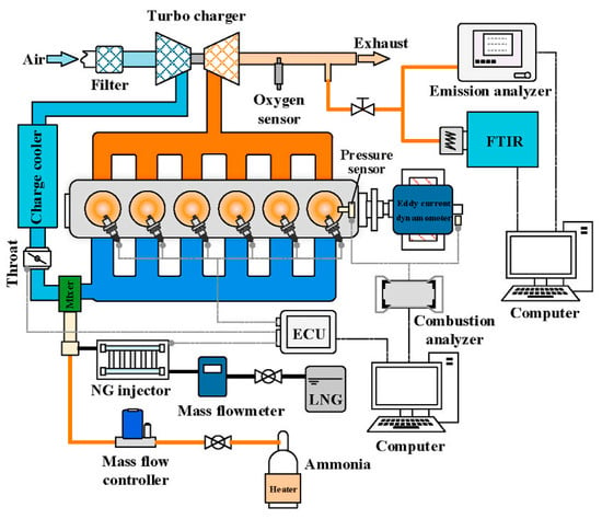
Figure 5.
The schematic diagram of the ammonia and natural gas mixed-combustion test process [39].
Under high CR operating conditions, Zhang et al. [40] compared the performance and combustion characteristics of NH3 fuel and CH4 engines using a single-cylinder SI engine and verified the decrease in engine performance caused by physical properties such as flame propagation speed and the ignition difficulty of NH3 fuel. Thermal imaging of combustion flame propagation indicated that the primary reason for the decrease in performance is the increase in the stagnant time of the NH3 combustion flame during the initial flame development process. While the flame propagation of CH4 is highly sensitive to temperature, NH3 flame propagation is primarily influenced by turbulence [41].
Kurien et al. [42] investigated the effects of XNH3 and workload on the combustion stability of SI engines fueled by NH3/CH4 blends. At a low engine load of 8 Nm, increasing XNH3 from 0 to 60% reduced the laminar burning velocity and flame propagation speed of the fuel mixture, causing the COV of indicated mean effective pressure (IMEP) to increase from 1.36% to 14.9%. Conversely, at a higher engine load of 16 Nm, increasing XNH3 from 0 to 60% narrowed the COV of IMEP from 14.9% to 4.3% [42]. The addition of NH3 reduces the combustion rate of the fuel mixture due to the lower combustion activity of NH3, resulting in decreased peak pressure (Pmax) and HRR [43]. High-speed camera images of flame propagation revealed that increasing XNH3 leads to a less wrinkled flame structure due to the addition of NH3. This weakens the combustion reaction rate, lowers the flame speed, and ultimately reduces the intensity of turbulent combustion. The decrease in NOx emissions is attributed to the lower combustion temperature caused by the addition of NH3 [43].
Simulation studies have investigated the attenuation mechanism of CH4 combustion induced by adding NH3. Adding NH3 fuel reduces the quantity of important radicals such as H and OH, leading to a decrease in the reaction rate of the fuel mixture. This causes a delay in the start of ignition (SOI) and prolongs the crank angles (CA) of 0~10° and 10~50° as XNH3 increases [43]. Increasing NH3 also increases NH3 slip, but it is beneficial that the slipped NH3 effectively promotes NO reduction. Oh et al. [44] introduced fuel comprising a mixture of NH3 and CH4 into a modified six-cylinder SI and found that as XNH3 continued to increase, the amount of NH3 slip increased and NO showed a trend of increasing first and then gradually reaching saturation. With the assistance of selective noncatalytic reduction (SNCR), NO emissions can be reduced to less than 10 ppm [44,45].
2.1.3. Combustion and Emission of NH3/H2 SI Engines
According to the data presented in Table 1, the flame propagation speed of H2 is 3.5 m/s, approximately 50 times faster than NH3‘s flame propagation speed. Despite NH3 possessing good anti-knock properties, the octane number of H2 is comparable to that of gasoline. Consequently, XH2 should not be excessively high. In the pursuit of determining the optimal XH2 threshold suitable for gasoline direct injection (GDI) engines, researchers [46] injected NH3 and H2 into the cooperative fuel research (CFR) engine manifold and investigated the impact of XNH3 on engine performance. Compared to traditional gasoline SI engines, efficiency and power witnessed a significant increase due to the potential for a higher CR. The findings also indicated that a fuel with XH2 = 10% exhibited the highest efficiency and power performance. When XH2 is lower than 60%, the deflagration tendency remains consistent at the boundary, but it changes significantly as XH2 increases continuously [46]. The optimal XH2 threshold of the NH3/H2 mixture is influenced by load and equivalence ratio. In the initial stages of combustion, H2 demonstrated a particularly noticeable accelerating effect, serving as an ignition promoter. Blending H2 with XH2 = 20% improved cyclic stability, prevented misfires, and resulted in optimal power output and indicated efficiencies comparable to stoichiometry. Increasing workload enhanced output performance and expanded operational limits concerning mixture composition [47].
Under high CRs of up to 13, the impact of adding H2 on the combustion characteristics of NH3 in a single-cylinder SI engine was analyzed. Additional H2 was found to worsen indicated thermal efficiency, as the high-temperature combustion of H2 resulted in significant heat transfer loss [48]. The visualization of combustion further revealed a critical threshold for the energy ratio between H2 and NH3. High-speed flame images depicting different H2/NH3 mixing ratios are shown in Figure 6. The addition of H2 to the air–NH3 mixture enhanced combustion speed, with optimal ratios being more dependent on engine load rather than speed. The NH3/H2 mixture was introduced into the intake manifold of a two-cylinder, four-stroke, low-speed marine engine. Experimental results [49] revealed that a minimum energy ratio of approximately XH2 = 7% was necessary for the engine to operate reliably at full load, while a ratio of 11% was required at half load. A proposed method involving the ignition of NH3 with an H2 jet flame successfully achieved full-load power output for the SI engine [49].
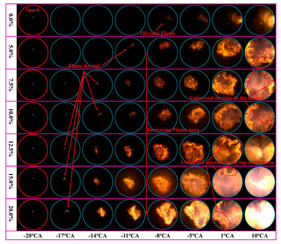
Figure 6.
High-speed flame images of different H2/NH3 mixing ratios [48].
Similarly, in the quest for the optimal XNH3 threshold in NH3/H2 mixed fuel, when XNH3 exceeded 80%, it could induce flame instability and even misfire. Under lean combustion conditions, the engine’s combustion performance is less sensitive to NH3 fractions [50]. The detailed combustion and emission characteristics of NH3-fueled SI mixed with other fuels under different operating conditions are outlined in Table 2.

Table 2.
Combustion and emissions of NH3-fueled SI with mixed fuel.
2.2. Structure Adjustment and Auxiliary Combustion Measures
2.2.1. Structure Adjustment and Strategy
The enhancement of combustion stability, flame propagation speed, and reduction of NOx emissions can be further achieved with the implementation of operation and control strategies [24]. The injection strategy of pilot fuel proves effective in reducing the minimum ignition energy of NH3 mixed fuel. This aids in establishing conditions for the formation of H and OH radicals, thereby shortening the initial stagnant time of NH3 combustion [54]. The vaporization of liquid NH3 demands a substantial amount of energy, leading to a significant decrease in the temperature of the air introduced into the cylinder. This, in turn, hinders the subsequent propagation of the turbulent flame, resulting in a decline in combustion efficiency or even potential misfire. Preheating proves beneficial by increasing the saturated vapor pressure, raising the initial temperature, and accelerating the reaction rate of fuel combustion [55]. Preheating also impacts NOx emissions, as illustrated in Figure 7.
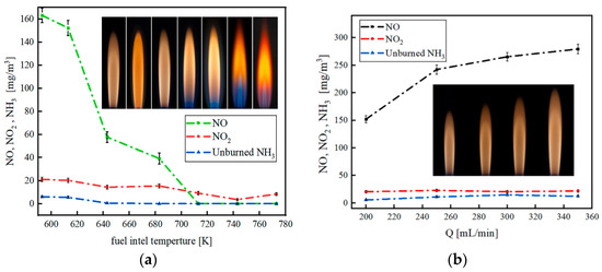
Figure 7.
The emissions with different preheating temperatures (a) and NH3 flow rates (b) [55].
Implementing a direct injection system, which mixes fuels and injects the mixture directly into the cylinder, eliminates the volume of the intake manifold and improves volumetric efficiency. Ryu et al. introduced a direct injection system in a CFR engine operating at 1800 rpm [56]. The engine output ranged from 1.25 to 2.75 kW, slightly lower than when using gasoline alone. Consequently, the higher levels of NH3 observed in the exhaust did not indicate a decline in combustion efficiency but rather reflected a greater supply of NH3. The key factor in improving combustion performance lies in the regular injection of the mixed fuel into the cylinder.
Pandey [57] compared the impact of ignition time on the combustion performance of an engine using a NH3/H2 mixture and pure H2 as fuel. This study utilized a 0.661 L, four-stroke, one-cylinder SI engine. The findings revealed that increasing the delayed ignition angle decreased the in-cylinder pressure of the NH3/H2 mixture and delayed Pmax. The sensitivity of in-cylinder pressure to the ignition angle was weak when H2 was burned. The peak of the HRR for the NH3/H2 mixed fuel occurred behind the top dead center (TDC), while the combustion of H2 mainly occurred in front of the TDC. The delay angle tended to result in a delayed peak value of HRR, typically elevating the in-cylinder pressure of pure H2. Whether it was an NH3/H2 mixture or pure H2, thermal efficiency was closely related to NOx emissions [57], as verified by [46].
Xin et al. [58] investigated the effect of variable valve timing (VVT) on a water-cooled, four-stroke, four-cylinder SI engine provided by the direct injection system under the Miller cycle. Advancing the intake valve timing and maintaining a larger valve overlap angle led to a decrease in combustion stability, an elongated flame development period (0–10 °CA), an increase in COV, an exceedance of MAXCOVP beyond 25%, and a rapid drop in BTE from 32.8% to 30%. However, retarding the intake valve timing by 25 °C increased IMEP and BMEP by 8% and 16%, respectively. Based on this research, advancing the intake valve timing is unsuitable for the Miller cycle H2-enriched NH3 engine [50,58,59].
In their comparison of control strategies on NH3-fueled SI engines, Xin et al. [50] evaluated three load control strategies: throttle, NH3/H2 mixing ratio, and equivalence ratio. Experimental research revealed that controlling the throttle broadened the engine’s output power threshold, enhanced BMEP, and maintained thermal efficiency above 33%. The NH3/H2 mixing ratio strategy, due to the fast propagation speed of the H2 flame, proves suitable for cold start conditions. The strategy of controlling the equivalence ratio can achieve higher thermal efficiency [59]. Hong et al. [60] investigated the effects of various load control strategies on the performance of NH3-fueled SI engines. Qualitative control of VVT combined with quantitative control enabled the engine to meet a wide range of BMEP regulations while maintaining BTE above 37% in most cases. As the air/fuel ratio increased from 1.0 to 2.0, BMEP and Pmax gradually decreased due to reduced fuel flow in the cycle. After increasing the air/fuel ratio, BTE initially increased and then decreased rapidly, reaching its maximum value of 39% when the air/fuel ratio was 1.4 [60].
Improving the CR is also a crucial measure for enhancing engine performance [37,61,62]. According to [63], the study found that increasing the CR from 9.41 to 11.51 increased Pmax by 59%. Additionally, under supercharged conditions, introducing 10% H2 into the mixture improved indicated efficiency by 37%. As the CR increased from 8 to 15, flame development accelerated, shortening the combustion period. Increasing XH2 from 5% to 21% improved brake power and increased BTE by 16.89% and 33%, respectively, at 1400 and 1800 rpm, but decreased volumetric efficiency by 13.64%. However, with increasing XH2 and CR, the exhaust temperature decreased, and the influence of XH2 on the exhaust temperature diminished [64]. Despite the relatively small amount of thermal NOx generated by fuel combustion, where fuel NOx was the primary component, an increase in XH2 led to a continuous rise in NOx due to the heightened peak temperature resulting from the addition of H2 [53].
The addition of mixed H2-rich reforming gas serves to increase the concentration of H and OH radicals, consequently elevating in-cylinder pressure and shortening the combustion duration. The introduction of 10% H2-rich reforming gas improves combustion efficiency by 96.3% and thermal efficiency by 43.6%. However, when the mixing ratio exceeds 12.5%, the negative impact becomes more pronounced [64]. Increasing the CR yields higher in-cylinder pressure and temperature, enhancing NH3 combustion and engine output performance while creating conditions conducive to NOx generation. Thus, striking a balance between engine output performance and NOx emissions is crucial. Auxiliary combustion technologies, such as exhaust gas recirculation (EGR), prove effective in improving engine output performance while maintaining NOx emissions within a controllable threshold [65,66,67].
2.2.2. Auxiliary Combustion Measures
Developing the application of NH3 fuel with minimal mechanical modifications to a given engine is a key focus [56,68], as are auxiliary combustion measures. Upon examining the impact of EGR on combustion performance by varying EGR rates from 0 to 25, it was found that pure H2 exacerbated combustion instability compared to the NH3/H2 mixture at higher EGR rates [57]. Implementing an initial EGR rate enhances the mean gas temperature by heating the intake with recirculated gases, thereby improving fuel combustion, boosting flame velocity, and enhancing the conversion of NH3 to N2. In summary, with the assistance of EGR (above 15%), the combustion stability advantage of NH3/H2 mixed fuel is significant [57]. This was attributed to the fast combustion rate of pure H2 and its shorter stagnant time compared to the NH3/H2 mixture, which explains the significant reduction in NOx emissions in the NH3/H2 mixture under highly delayed ignition conditions.
Increasing the number of spark plugs effectively reduces NOx emissions while enhancing flame propagation speed. Uddeen et al. [69] modified the existing engine ignition system to equip it with four spark plugs, which showed that multi-spark-plug ignition promotes flame propagation, shortens the initial flame retention time, and improves the pure NH3 combustion rate. However, it increases in-cylinder pressure and temperature, creating an unfavorable environment for NOx formation. To enhance combustion performance, Liu et al. [70] employed pre-chamber turbulent jet ignition (TJI) technology on a 0.5 L, one-cylinder, four-stroke SI engine with a CR of 14, as shown in Figure 8. TJI generates turbulent jet flames, enabling multi-point ignition and stable combustion for low-reactivity fuel mixtures in the combustion chamber [70]. Adopting the TJI mode shortens combustion time and delays ignition time owing to an increase in ignition energy, which is beneficial to improving the combustion stability of the NH3 SI and increasing the combustion rate. Regardless of the ignition method, the NOx and NH3 emissions of NH3 SI engines are higher [70].

Figure 8.
The basic configuration of the TJI system [70].
The instability of NH3 combustion poses challenges for cold-starting NH3 SI engines. Koike et al. [71] pioneered the use of H2-rich reforming gas (resulting from the online thermal decomposition of NH3) for cold-starting an SI engine. Achieving a fast cold start was possible when the NH3/H2 mixing ratio was 1:2, and stable operation was maintained under no-load conditions. To address the emissions of unburned NH3 during the cold start and transition to stable operation, it is crucial to implement post-treatment measures for emissions. Test results indicated that with the assistance of a three-way catalyst, NH3 emissions were close to zero [71]. The detailed combustion and emission characteristics of NH3 SI engines, assisted by changes in structure and strategy, are presented in Table 3.

Table 3.
Combustion and emission of NH3-fueled SI engines assisted by changing the structure and strategy.
In summary, the pathways to enhance combustion and reduce emissions in NH3 SI engines are illustrated in Figure 9. The addition of other fuels results in a significant increase in flame propagation speed, a reduction in the flame stagnation time during the initial stage of combustion, and a notable improvement in BTE. However, this comes at the cost of a substantial increase in fuel–NOx emissions. Altering the structure of an SI engine or adjusting fuel injection or ignition timing can effectively raise pressure and temperature in the cylinder, leading to a significant upward trend in engine BTE. Nevertheless, NOx emissions and NH3 slip are not satisfactorily addressed. The incorporation of auxiliary combustion technology proves effective in enhancing NH3 combustion efficiency and consequently reducing NOx emissions.
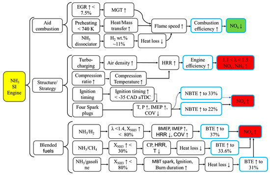
Figure 9.
Pathways to promote combustion and emission reduction in NH3 SI engines. ↓ and ↑ are down and up, respectively.
2.3. Exhaust Gas Aftertreatment to Minimize NOx Emissions from SI Engines
For traditional fuel SI engines, NOx emissions can meet relevant emission standards through some structural improvements and some operational strategy optimizations. For NH3 fuel engines, fuel–NOx is a major component of NOx emissions. It is necessary to adopt after-treatment of emissions similar to SCR systems to make NOx emissions meet emission standards [74]. Ammonia is a common reducing agent for NOx, so the presence of unburned ammonia fuel in the exhaust is beneficial to reducing NOx emissions. Studies show that rich conditions can lead to elevated ammonia levels, while nitrous oxide generation remains low in all circumstances [75]. In addition, in order to reduce the problem of low fuel utilization caused by rich combustion, Vitaly et al. used a lean SI engine to install an ammonia device that can store upstream generated ammonia on the original supporting aftertreatment system platform, thereby achieving the effect of reducing NOx emissions [76].
When pure NH3 or NH3 mixed with other active fuels is burned, NOx emissions increase significantly, but the advantage of ammonia as a nitrogen oxide reducing agent increases. Oh et al. [44] used the aftertreatment system of the original SI engine, including a selective catalytic reduction system and an ammonia oxidation catalyst, to study the characteristics of nitrogen oxides and residual ammonia before and after the exhaust flow through SCR under different air/fuel ratios and fuel mixing ratios, and found that as the ammonia energy fraction increased, the temperature during combustion decreased significantly. Although the fuel–NOx emissions increased, the NOx emissions after passing through the SCR system tended to be saturated. At the same time, it was found that the remaining ammonia can reduce the NO in the exhaust gas before passing through the SCR at a suitable temperature. When passing through the SCR system, the remaining ammonia will reduce the remaining NO again, and the final NO emission can be controlled within 10 ppm. Other NOx emissions are less than hundreds of ppm. After the remaining ammonia acts as a NOx-reducing agent repeatedly, the residual ammonia is within 10 ppm.
3. Ammonia Used in Compression Ignition Engines
The air injected into the cylinder undergoes compression to reach a specific temperature and pressure due to piston movement. Subsequently, fuels are introduced into the cylinder through atomization, ignition, and expansion [77]. For CI engines, the fuel must possess good auto-ignition performance and a short ignition delay period [78]. The challenging ignition characteristics of NH3 make its normal operation in CI engines more difficult than in SI engines.
NH3 has the most significant impact on improving the ignition delay period of diesel, while it has the smallest effect on improving Pmax and efficiency. Several potential strategies for using NH3 as a CI fuel include (a) blended fuel combustion [79], (b) high CR [80], and (c) injection strategies [81,82]. Overcoming the combustion challenges of NH3 fuel often requires a combination of these measures. An effective strategy to enhance the combustion performance of NH3 is to blend it with a more reactive fuel. Similar to SI engines, if the auto-ignition temperature of the fuel is higher than the cylinder temperature at the end of compression, it can be mixed with NH3 fuel and injected into the combustion chamber of the CI engine to mitigate the defects in the physical characteristics of NH3 fuel. The engine’s performance during combustion heavily depends on the cetane number (CN) of the mixed fuel, where a higher CN results in optimal performance with shorter ignition delays and optimum combustion efficiencies.
3.1. Mixing Fuels with Strong Activity
3.1.1. Combustion and Emission of NH3/Diesel CI Engines
Regardless of whether NH3 fuel is supplied to the engine in a liquid or gaseous state, it can meet typical engine load and thermal efficiency requirements through a blended fuel premix mode ignited by the pilot fuel [83]. The release of heat is faster in the case of liquid NH3, leading to higher cylinder pressure. Compared to liquid NH3, the HRR decreases by 50% and 25% and the pressure reduces by 6.5% and 11.5% under the energy supply of gaseous NH3 at 100% and 80%, respectively. Unfortunately, NOx emissions far exceed Tier III limits [83]. For achieving the same output power as diesel in CI engines, the intake manifold of a four-cylinder CI engine is slightly modified to be suitable for the direct NH3/diesel injection strategy. As the XNH3 increased, the CA corresponding to the Pmax in the cylinder also increased while the peak value gradually decreased (from 9.5 to 7.5 MPa). Additionally, the HRR showed a significant increase (from 0.04 to 0.1), and the emission of NO under blended-fuel operation (XNH3 < 40%) decreased significantly, resulting in lower thermal NO emissions but higher fuel–NO emissions (XNH3 > 60%) [84]. The performance of a CI engine fueled by a NH3–diesel blend as shown in Figure 10. By adopting a split diesel injection strategy (SODI), combustion thermal efficiency has been increased to 39.72% but also a resulting 83.5% decrease in unburned NH3 emissions, surpassing that of pure diesel [78]. Leveraging the advantages of the split fuel injection strategy, optimizations such as SODI-pre and SODI-main can be implemented [85]. By reasonably controlling the injection time of diesel and NH3, the NH3 combustion speed could be accelerated, maintaining liquid NH3 in a stable state throughout the entire combustion stage [86].
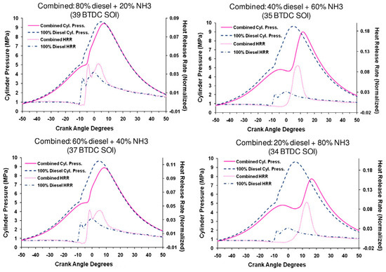
Figure 10.
The performance of a CI engine fueled by a NH3–diesel blend [84].
Achieving a high injection pressure is crucial to ensuring effective atomization of the fuel mixture [87]. Zhou et al. [88] developed a combustion model for a CI engine under the high-pressure direct fuel injection mode (HPDF). Compared to the commercial low-pressure, blended-fueled direct fuel injection mode (LPDF), this mode can reduce NOx emissions by approximately 47% while maintaining the same thermal efficiency. Utilizing the same spray device, Zhu et al. [89] determined that the NH3 addition threshold is unsuitable for exceeding 40%, considering the impact of NH3 addition on ignition delay, premixing efficiency, and NOx emissions [88]. CI ignited by the pilot fuels under two modes as shown in Figure 11.
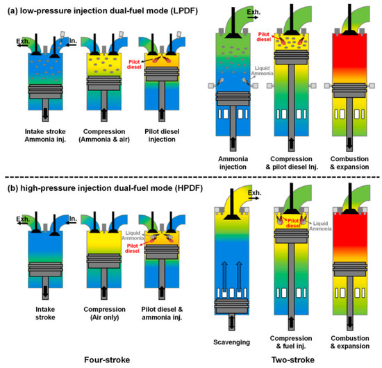
Figure 11.
CI ignited by the pilot fuels under two modes [88].
Numerical simulation results have successfully validated the feasibility of the new high-temperature cylinder gas recirculation (HTCGR) technology [88]. The new HTCGR technology as shown in Figure 12. Consequently, it is crucial to investigate the impact of mixing combustion-generated water with NH3 on engine combustion and emissions. Frost et al. [90] conducted combined numerical analysis and experimental research to explore the effects of different concentrations of NH4OH (ammonium hydroxide) on CI combustion under various workloads. At an IMEP of 4 bar, although the ignition delay time is longer than that of pure diesel, NH3 can be ignited and contribute 25% of the engine load. Increasing NH4OH concentration increases NOx emissions, as the elevated cylinder temperature during this stage is closely related to NOx emissions. After continuously increasing NH4OH concentration and contributing 20% to the engine load, NOx levels decrease. Excessive NH3 concentration increases combustion instability and lowers the in-cylinder temperature [91]. These findings align with results in the literature [92], where the addition of a NH3 solution reduces combustion pressure and HRR, increases engine diameter and ignition delay, reduces engine performance, and significantly decreases NOx emissions.

Figure 12.
The new HTCGR technology [81,88].
In addition to the NH3 energy ratio, factors such as engine speed and load also influence engine combustion and emissions. Shahin et al. [93] studied the impact of NH3 energy ratio, speed, and load on combustion and emissions. In the medium load range, total fuel consumption, as measured by specific fuel consumption, decreased with increasing load. Additionally, the presence of air fuel (NH3 injection in the air) resulted in an increase in total fuel consumption under slightly higher load conditions, with a similar trend observed for NOx emissions. Optimal outcomes regarding engine performance and exhaust emissions were observed for NH3 fumigation at 2600 rpm. Under 8 Nm and 2600 rpm, the maximum effective efficiency increased by 15.05% with an air/fuel ratio of 8.5% [93]. A mixture of 25% NH3 and 75% water solution was used and injected into the intake through a carburetor with an adjustable main nozzle. It was proven that NH3 can reduce NOx by more than 70% in the parameters analyzed, while the effect on brake-specific consumption is negligible. Compared to pure diesel CI, the mixture (with 10% H2 content) increased peak pressure by 5.3% and maximum temperature by 5.7% [94]. Combustion and emission of a NH3 CI engine with mixed fuel, as shown in Table 4.

Table 4.
Combustion and emission of a NH3 CI engine with mixed fuel.
3.1.2. Combustion and Emission of NH3/H2 CI Engines
The higher CR and intake pressure work together to assist NH3 combustion, reducing the required intake temperature, which is closely related to NOx emissions, thereby maximizing IMEP and efficiency. However, strategies are needed to recover the loss of combustion efficiency and to avoid N2O, which is prone to production below 1400 K [98]. To understand the feasibility of clean and efficient NH3 combustion, the CR of the HCCI test stand was modified to 22:1, increasing IMEP by 67% with varying levels of XNH3 from 0 to 95%. However, when the Pmax exceeds 10 bar/CAD, heat and friction losses sharply rise, ultimately limiting IMEP, indicating that NH3 inhibits the overall combustion rate [97]. By adjusting the CR and injection time of the NH3/H2-fueled CI engines, NOx emissions can be brought into compliance with Tier III emission standards while ensuring that the engine maintains sufficient power [61]. The best injection timing combination in the engine not only has optimum power and economy but also allows the engine’s NOx emissions to meet Tier II emission standards [99].
Building on these research results [61,99], Wang et al. [100,101] conducted a more detailed study on the influence of the NH3/H2 energy ratio on the pressure in the engine cylinder, power, and emissions. Mixing H2 from 0 to 30% increased the cylinder explosion pressure by 10.7% and power by 1.8% while reducing the fuel consumption rate and NH3 escape by 0.3% and 99.1%, respectively. Although NOx emissions increased by 58.8%, the comprehensive performance of the CI engine after H2 mixing combustion was improved. With the help of a small amount of diesel ignition, the engine adopted a direct injection method, and when using a mixture of NH3 and H2 as fuel, the optimal XH2 was found to be 30% [101]. Pathways to promote combustion and emission reduction in NH3 CI engines as shown in Figure 13.
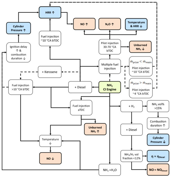
Figure 13.
Pathways to promote combustion and emission reduction in NH3 CI engines [102]. ↓ and ↑ are down and up respectively.
Due to the advantage of faster transmission speed that NH3/H2 combustion possesses and considering the convenience of energy transportation, NH3 decomposition mixed with H2 is an important measure to reduce the difficulty of H2 storage and transportation. Gill et al. [103] conducted experiments to study the combustion and emission properties of various fuel types, including diesel, pure NH3, pure H2, NH3/H2/N2 (1%, 75%, 24%), and NH3/H2/N2 (2%, 75%, 23%). The results showed that incorporating more H2 and NH3 had a negative impact on BTE at both loads compared to pure diesel. At high loads, BTE with pure NH3 was superior to BTE with added decomposition H2, which was similar at low loads. Upon reducing the cylinder pressure from 5 bar to 3 bar, the total COV decreased by approximately 50%, BTE decreased by around 26%, and emissions of NOx increased by about 27% [103].
3.1.3. Combustion and Emission of NH3/DME CI Engines
Dimethyl ether (DME) shares physical properties with liquefied petroleum gas, featuring a high CN and low ignition temperature [104]. When mixed with other fuels, DME can enhance the combustion of low-activity fuels [105]. The addition of DME increases the reactivity of NH3 and reduces ignition delay times, although this influence decreases with increasing DME, temperature, and pressure. This promotional effect is attributed to the increased formation rate and concentration of free radicals, especially OH [95].
Despite the inevitable increase in NOx emissions due to the nitrogen bound in NH3, improvements can be achieved under the same operating conditions by increasing the injection pressure. Using XNH3 (20% and 40%) results in an extended ignition delay time due to the elevated auto-ignition temperature and sluggish flame propagation speed, limiting the engine’s load output. Higher NH3 concentrations, coupled with higher injection pressures, can enhance the fuel–air mixture for better combustion and achieve a higher engine load output [106]. Given the high auto-ignition temperature of NH3, the optimal injection time needs to be advanced with the increase in XNH3. The suitable injection timing range for a DME/NH3 blend (40%/60%) was determined to be 90 to 340 °CA before top dead center (BTDC). This advanced injection timing resulted in the engine displaying HCCI combustion characteristics [96]. Combustion and emission of NH3 CI engines assisted by changing the structure and strategy as shown in Table 5.

Table 5.
Combustion and emission of NH3 CI engines assisted by changing the structure and strategy.
3.2. Exhaust Gas Aftertreatment to Minimize NOx Emissions from CI Engines
To address the NOx emission issue in NH3-fueled CI engines, the use of NH3 for the selective catalytic reduction (SCR) of NOx is prevalent. For safety considerations, vehicle aqueous urea was injected into the aftertreatment device as an NH3 carrier. However, the uneven distribution of aqueous urea can impact catalytic efficiency. In this context, researchers compared the impact of pressure-driven ejectors and air-assisted ejectors on the uneven distribution of aqueous urea [109]. The results indicate that air-assisted injection has clear advantages in both droplet size and injection speed. However, under the influence of airflow, aqueous urea is prone to solidify. In response, researchers designed I-type and L-type ejectors, influencing the amount and uniformity of NH3 injection, respectively [110].
To enhance the mixing ratio of vehicle urea and exhaust gas and improve volume utilization, the influence of mixing chambers and swirl mixers with NOx conversion was compared [111]. This comparison found that the NOx conversion efficiency can be increased by 61.3%, 76.2%, and 86.3%, respectively, by using the mixing chamber, the swirl mixer, and a combination of the two [111]. Ko et al. [112] observed that NH3 slip is inevitable in the process of NOx conversion, especially during engine start, where it is challenging to eliminate NH3 slip. However, Kuta et al. [92] discovered that NH3 slip provides the possibility to re-activate the SCR system and improve its effectiveness under different engine operating conditions. The key factor affecting effectiveness is temperature, which can be easily controlled by modifying the structure of the exhaust device. SCR systems as shown in Figure 14.

Figure 14.
SCR systems [110,112].
4. Ammonia Used in Gas Turbines
The gas turbine (GT) is an internal combustion power machine that utilizes high-pressure air compressed by the compressor and fuel injected into the combustion chamber. The mixture of air and fuel ignites, creating high-temperature gas. Subsequently, this gas expands, driving the turbine to work externally. Combustion stability is achieved when the flame propagation speed matches the mixture flow velocity. The GT imposes strict requirements on fuel performance due to its high inlet flow rate, which is essential for maintaining stable combustion.
The combustion chamber of the GT exhibits distinctive features. These include high temperatures, elevated airflow velocity (leading to unstable flames that are prone to extinguishing, making combustion completion challenging), heightened combustion intensity (requiring a large fuel supply per unit volume and high combustion speed, necessitating a uniform outlet temperature field), and a high excess coefficient. The latter is particularly notable in areas of poor combustion, where working conditions are variable. These characteristics are illustrated in Figure 15.
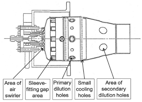
Figure 15.
Schematic diagram of combustion chamber structure for GTs [113].
Verkamp et al. [114] experimentally studied the performance of the burner, minimum ignition energy, quenching distance, flame stability limit, and other physical properties of a NH3/air mixture in a gas turbine burner. According to the existing combustion characteristics, it is predicted that pure NH3 cannot be used as an alternative fuel for fueling GT power devices [115] unless the energy of the ignition system is increased and the injection strategy is optimized. To understand the NH3 spray characteristics more comprehensively, Li et al. [115] established the relationship between superheat, fuel viscosity, temperature, ambient density, and NH3 spray characteristics in a constant volume chamber. These experimental data will provide basic information for understanding NH3 combustion. Based on the existing models of NH3 sprays, An et al. [116] compared the simulation results with the recently published experimental data of NH3 flash evaporation spray vaporization and discussed the effectiveness of the liquid NH3 phase transition model concerning penetration length, diameter, and spray morphology. Through model evaluation, it was found that combining and optimizing multiple evaporation models to match the actual evaporation characteristics of liquid NH3 would be an effective pathway.
4.1. Mixing Fuels with Strong Activity
4.1.1. Mixing NH3 with CH4
The low heat value and flame propagation speed of CH4 are higher than those of NH3. Adding CH4 proves advantageous in enhancing the combustion efficiency of NH3 [117]. Zhang et al. [118] discovered that incorporating CH4 can broaden the ignition threshold of NH3 flames. Additionally, the latent heat of CH4 evaporation is lower than that of NH3. The introduction of CH4 helps mitigate the inhomogeneity of fuel droplets, reducing heat transfer and minimizing NOx emissions and NH3 slip [119]. Consequently, increasing the inlet temperature of CH4/NH3 mixed fuel and minimizing heat loss from the combustion chamber wall can compensate for fuel droplet spray-induced heat transfer losses. This improves droplet spray combustion characteristics and further reduces pollutant emissions [120]. The GT operated stably until XNH3 reached 63% [121]. Beyond 22% XNH3, a noticeable drop in combustion efficiency and thermal efficiency occurred. A comparison between the NH3 flame and the mixed fuel flame containing 10% CH4, with different equivalence ratios, is illustrated in Figure 16.
For the multi-stage swirl combustor, an equivalence ratio of 1.2 is optimal for controlling minimum NO and NH3 emissions [122]. However, for a single-stage swirl combustor, the optimal equivalence ratio differs. Considering the relationship between NOx emissions and unburned fuel, an equivalence ratio of 1.06 is optimal when XNH3 is 70% [123]. Irrespective of the NH3 fraction, an equivalence ratio slightly greater than 1.05 is optimal for lower NO [124,125].
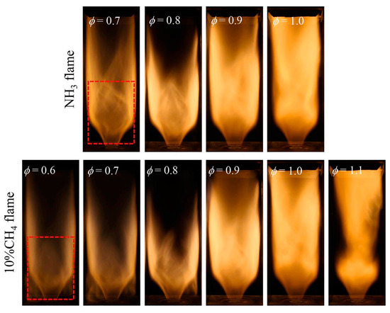
Figure 16.
Comparison of the NH3 flame and the mixed fuel flame containing 10% CH4 with different equivalence ratios [126].
4.1.2. Mixing NH3 with H2
It has been demonstrated that the combustion intensity of NH3/air can be enhanced by incorporating active fuels such as CH4 and H2. When a GT was fueled by NH3/H2/air and CH4/air, it became evident that the GT fueled by NH3/H2/air exhibited superior performance, with a 37% higher efficiency. However, this improvement comes at the cost of unsatisfactory NOx emissions. Zhang et al. [126] delved into the impact of CH4 and H2 on the emission characteristics of an NH3-fueled GT burner. At an equivalence ratio of 0.1, whether it was NH3/H2, NH3/CH4, or NH3 alone, the variations in NO and NO2 were similar [126]. As the mixing ratio exceeded 0.1, owing to the higher combustion temperature, NH3/CH4 demonstrated notable performance in NOx emissions. Utilizing the dynamic thickened flame model, it was verified that NH3 co-fired with 10% H2 is a promising mixture capable of enhancing combustion stability and maintaining NOx emissions within a controllable threshold [127]. However, focusing on NOx reduction alone results in lower efficiencies than CH4, emphasizing the urgent need for new injection and ignition technologies to simultaneously reduce nitrogen oxides and unburned NH3 emissions while maintaining power outputs [128]. Combustion techniques and combustor design for efficient combustion and low NOx emission from an ammonia MGT swirl combustor are proposed, NOx emission of 42 ppm was achieved [129]. Basic research parameters of a GT as shown in Figure 17.
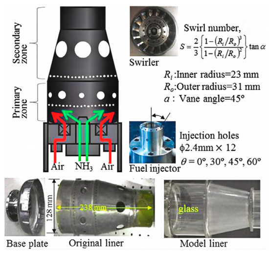
Figure 17.
Basic research parameters of a GT [129].
To achieve high efficiency, fuel steam is directly introduced into the combustion chamber. Combined with other energy-saving technologies, this approach can achieve a total efficiency of 59%, while emissions still comply with European NOx thresholds [130]. Lean premixed combustion technology, along with swirl-induced flame stabilization, represents one method for reducing NOx emissions in traditional GTs. This method demonstrates that NOx emissions remain below 30 ppm even when XNH3 reaches 40%, using air-staged combustion fueled by the NH3/CH4 mixture [131].
In the pursuit of understanding the NOx emission mechanism, researchers conducted studies on chemical kinetics models, incorporating actual NOx emission tests to validate and refine the model parameters, ensuring the reliability of model simulation. Xiao et al. [132] compared five different chemical kinetics models to evaluate their accuracy in representing reaction dynamics in real GT burner conditions. These chemical kinetic models can simulate and predict the chemical pathway of CH4 as an NH3 combustion enhancer and the key reactions leading to NOx emissions. Through the analysis of the chemical reaction pathway, it was observed that the addition of CH4 promoted the formation of OH radicals, subsequently enhancing NH3 conversion. Even in mixtures with lower NH3 content, free radicals generated in the CH4 oxidation pathway contributed to the formation of NOx [133].
Various combustion mechanisms suggest that during NH3/H2 premixed combustion, NO is primarily reduced to NNH [134]. When burning the NH3/H2 mixture mixed with steam, the decomposition of H2O promotes significant H, O, and OH radicals. While this hinders the formation of NO, the increased presence of OH radicals promotes the formation of NH2, subsequently leading to the formation of NO [135]. These findings have been confirmed in [128] on NH3/H2 lean premixed combustion in a swirl GT combustor. The change in NOx emissions aligns with the concentration pattern of OH radicals in the combustion chamber, underscoring the significance of OH radicals in fuel NOx [136]. The increase in pressure enhances the reaction of NH + NO = N2O + H, with higher pressure resulting in a lower NO fraction [137].
With a 40% increase in NH3 addition, the OH concentration consistently follows the temperature trend [138]. Analyzing the NO reaction pathway influenced by temperature reveals that the main factor affecting NO formation in the flame zone is HNO free radicals, while the primary factor influencing NO reduction in the post-flame zone is NHi free radicals [138]. The addition of H2 increases the concentrations of H, NH, and NH2 at the flame root, leading to increased NO consumption [127].
4.2. Structure Adjustment and Auxiliary Combustion Measures
Due to the significant advantages of plasma in enhancing the NH3 decomposition rate and laminar combustion rate, as illustrated in Figure 18, plasma-assisted combustion strategies are extensively employed in GT ignition systems [139]. Scientists utilize nanosecond plasma discharge to increase pulse energy density and have observed that the flame combustion rate (XH2 = 12%) remains consistent with conventional fuel [133].
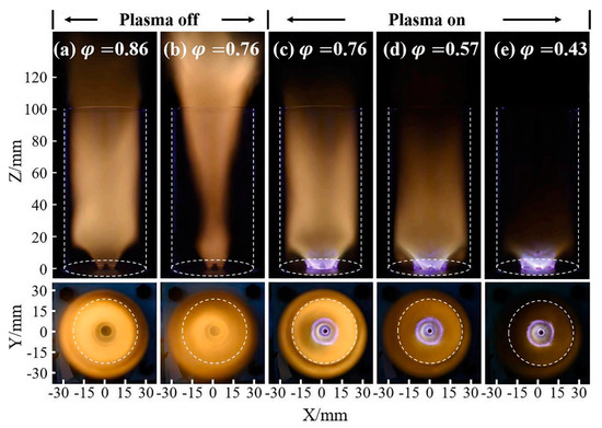
Figure 18.
The effects of plasma on a swirling NH3 flame [41,139].
To effectively reduce NOx emissions, it is recommended to employ the non-premixed injection mode and maintain an equivalence ratio of 0.9 to 1.2 when operating with a higher proportion of NH3 in the fuel mixture [140]. Kurata et al. [113] successfully developed a non-premixed combustion chamber suitable for NH3 combustion with low NOx emissions, capable of achieving a power output of up to 40 kW under pure NH3 combustion conditions, effectively demonstrating the potential of NH3 combustion to achieve dual carbon targets [141]. The lower swirl combustion burner exhibited a wider uniform reaction area, fewer hot spots in the reaction zone, and a more uniform temperature distribution. The maximum NOx concentration in the reaction zone with the higher swirl combustion burner was twice that of the lower swirl combustion burner [142].
Although a larger equivalence ratio contributes to lower NOx emissions, it also compromises the overall efficiency of the GT. Okafor et al. [121] determined that the optimal primary combustion zone for low NOx emissions corresponds to an equivalence ratio ranging from 1.30 to 1.35, depending on the ammonia mole fraction (XNH3). Lean-rich combustion of CH4/NH3 mixtures yielded lower NOx emissions compared to pure NH3 combustion due to the faster flame speed of CH4/NH3 mixtures, which reduced NOx formation in the secondary combustion zone [121]. Somarathne et al. [119] conducted a comparative analysis of combustion and emission characteristics of pure NH3 and CH4 in a combustor designed for a rich-lean GT. NO concentration was primarily influenced by local temperature. While cooling the combustor wall considerably impacted NH3 oxidation and NH3 slip, it also reduced NO emissions by lowering the concentration of OH radicals in the flame zone due to wall heat losses [119]. Lean premixed flames, a promising technique for hydrocarbon combustion, effectively comply with strict legislative regulations on emissions of combustion pollutants in GT combustion but lead to combustion instability. Lean-rich combustion systems can achieve minimal NO levels while producing zero unburnt NH3 emissions [113]. NOx emissions are significantly influenced by the mixture stoichiometry [143]. Moreover, with increasing XNH3, the decrease in NOx emissions becomes more pronounced as the equivalence ratio increases [129]. In summary, Figure 19 illustrates the technical approach for improving the combustion and emission performance of NH3-fueled GTs. NOx emissions and NH3 slip can be effectively reduced by optimizing the structure and strategy and incorporating auxiliary combustion measures. While blending highly active fuels can improve thermal efficiency, it is relatively easy to increase NOx emissions.
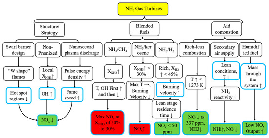
Figure 19.
Pathways to promote combustion and emission reduction in NH3 GTs. ↓, ↑, → are down, up, unchanged respectively.
5. NH3 Fuel Cells
5.1. Application of NH3 in FCs
The breakthrough in the research and development of NH3 FCs can be attributed to the large-scale production of fuel, application processes that significantly reduce carbon emissions, and other advantages [10,144]. NH3 FCs are classified based on different types of fuel supply and electrolytes [145], as illustrated in Figure 20. In the pursuit of higher power density, scholars have conducted studies on factors influencing the performance of NH3 FCs, including reaction temperature, electrolyte thickness, electrolyte type, and electrode type. The research results on the performance of NH3 FCs are combined, and different power segments are depicted, in Figure 21 [146].
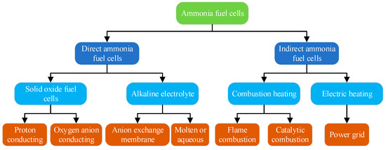
Figure 20.
Classification of NH3 FCs.
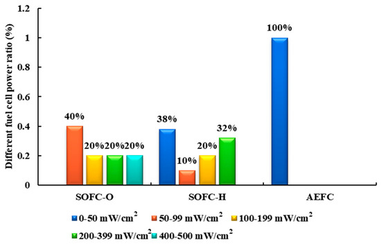
Figure 21.
Power interval distribution of direct NH3 FCs.
According to Figure 21, the solid oxide fuel cell (SOFC) fueled with NH3 demonstrates superior power output compared to the alkaline electrolyte fuel cell (AEFC). The highest power density reported for AEFC in [142] is only 467 mW/cm2, and the volume power density is a mere 8 kW/m3 [147].
Indirect ammonia FCs (IA-FCs) utilize H2 derived from the thermal decomposition of NH3 as fuel, offering a wider range of applications. Researchers have conducted preliminary studies on the performance of IA-FCs [147]. Although indirect ammonia–proton exchange membrane fuel cells (IA-PEMFC) exhibit slightly lower efficiency, they boast remarkable power density, with a volume power density approximately 15.5 times that of IA-AEFCs and 12.2 times that of SOFCs fueled with NH3 [146].
5.2. Research Routes of IA-PEMFCs
Research on IA-PEMFCs is progressively deepening, with three main research routes. Firstly, the issue of heat supply through electric heating emerges as a stable and easily adjustable heating technique [148]. However, the use of the end product, electricity, may inevitably reduce the overall power generation efficiency for FCs [149]. This method is primarily employed to provide a stable heat source for verifying the effectiveness of catalysts (such as zeolite-based [150], Mo2N [151], Ru-Al monoliths [152], nickel-based [153], and Ce-doped [154]) and other improvement measures for FCs [153]. Catalytic combustion, a flameless combustion mode, offers advantages such as high combustion efficiency, a stable and controllable process, and relatively uniform and stable combustion. The catalytic combustion heating mode can decompose NH3 to form an ideal exothermic and endothermic coupling system with high volume utilization efficiency. Currently, NH3 catalytic combustion is primarily utilized in power equipment with small power and strict volume requirements. Ongoing research focuses on catalysts to enhance catalytic combustion efficiency (including Mn/Bi/Al catalysts [155], platinum [156], Ru/Al2O3 [157], and Pt gauzes/oxide monolithic layers [158]) and reactor structure [159]. Flame combustion, on the other hand, is a simple, direct, and rough heating method with high combustion temperature but low combustion efficiency. Current research on NH3 flame combustion primarily concentrates on the stability of NH3 combustion (including pure NH3 combustion [55,160,161], mixed combustion [162,163,164], and auxiliary combustion [31,165]) and reducing NOx emissions [166,167,168,169]. The chemical reaction process in direct NH3 FCs and IA-PEMFCs is illustrated in Figure 22.
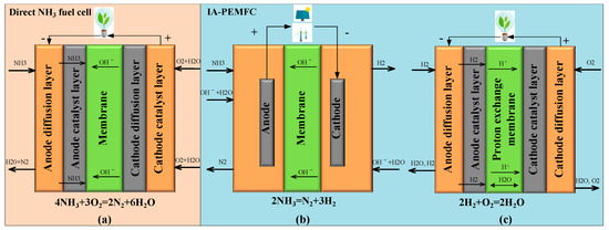
Figure 22.
Chemical reaction process in direct NH3 FCs (a) and IA-PEMFCs ((b) NH3 decomposition, (c) PEMFC).
The second research route involves purifying the gas resulting from NH3 decomposition. In an ideal state, the gas would be a 1:3 mixture of N2 and H2. However, achieving a 100% NH3 decomposition rate is highly unlikely, and the gas will inevitably contain some undecomposed NH3. Additionally, NH3 decomposition gas contains 25% N2, and the presence of N2 is ineffective, further reducing the mass transfer effect [170,171]. However, PEMFCs are highly sensitive to NH3 content, which needs to be below 0.1 ppm for optimal performance [172]. Therefore, to improve the service life and power generation efficiency of subsequent FCs, the purification of NH3 decomposition gas is of great significance [173]. Currently, the purification of NH3 decomposition gas is primarily studied in H2-selective membranes [174], membrane reactors [175,176,177], and the liquefaction of N2 [178].
The third research route involves developing a FC structure suitable for the mixture of N2 and H2. Zhao et al. [179] demonstrated through experiments that it was challenging for an air-cooled H2–air PEMFC to function properly when an N2 and H2 mixture was used as the anode fuel. Subsequent research by Zhao et al. [180] indicated that shortening the flow channel length could enhance the stability of PEMFCs using a N2 and H2 mixture as fuel, as revealed through simulation analysis. Building on this work, Hu et al. [181] further investigated the water–heat–gas distribution of NH3/H2 PEMFCs under parallel flow channels. They found that fuel dead zones tended to appear at the tail of long parallel flow channels, impacting the normal operation of the FC. Considering the mass transfer characteristics of the N2/H2 mixture, Hu et al. [147] employed biomimicry to construct a hedge-type triangular flow channel, optimizing it for N2/H2 mixture compatibility and determining size parameters for optimal output performance. These studies demonstrate that, by employing flow channel optimization and other measures, NH3 decomposition gas can be directly injected into PEMFCs after removing NH3, resulting in higher power density than conventional FCs.
Hunter et al. [182] explored the system efficiency of IA-PEMFCs by integrating an NH3 cracking system, a purification unit, and a small PEMFC. The integration of a complete system for NH3 decomposition and NH3 decomposition gas purification, based on light metal amide imide with a 100 W PEMFC, is a significant milestone for the promotion and application of indirect NH3 FCs. Ye et al. [148] used the heating method of NH3/H2 mixed flame combustion to heat NH3 decomposition gas and added a NOx emission reduction treatment device to analyze the fuel utilization efficiency of the indirect NH3 FC system. Compared with conventional fuel-oil engines, the fuel utilization efficiency of the IA-PEMFC system is higher than that of water taxis but lower than cargo ships [148]. Lin et al. [183] categorized the heat sources needed for NH3 decomposition in the IA-PEMFC system into three heating modes: electric heating, N2/H2 flame combustion, and PEMFC anode tail gas combustion. They then compared and analyzed the system efficiency under each mode. Among them, the IA-PEMFC system, where the combustion of NH3 decomposition gas provided heat for NH3 decomposition, had the highest efficiency, accounting for 56.6%. Building on the IA-PEMFC system, Zhao et al. [184] established a complete system that burned the anode tail gas of PEMFC to supply the heat required by the decomposer. When the heat from firing the anode tail gas is insufficient, fueling the NH3 gas to supply the required heat to the decomposer becomes a compensatory strategy. The system’s energy efficiency is found to be 45% through simulation analysis.
The optimization results of system efficiency in the IA-PEMFC system above are inevitably different, as shown in Figure 23, due to the varying catalyst activity, catalyst dose, regenerator efficiency, and other parameters used in the experiment and simulation. However, the successful integration of the IA-PEMFC system above fully demonstrates the feasibility of the system. This paves the way for the future advancement of IA-PEMFCs.
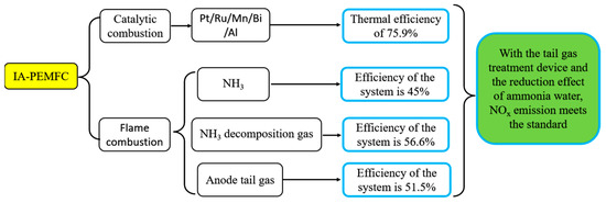
Figure 23.
Research routes of IA-PEMFCs.
5.3. NOx Emission and NH3 Slip in IA-PEMFCs
NH3, while not classified as a greenhouse gas, is considered toxic. Therefore, NH3 slip serves as an indicator of harmful emissions. NH3 slip primarily occurs in direct NH3 FCs and can be mitigated by factors such as purge strategy optimization of the flow channel structure, catalyst selection, or operating conditions. Additionally, water generation at the anode aids in NH3 absorption. Indirect NH3 FCs primarily emit NOx, mainly due to intermediate products generated by catalytic and flame combustion. Unlike GTs, which have a turbulent swirl parameter design, SI engines, which involve ignition time and flame diffusion combustion, or CI engines, which involve ignition time and premix combustion, NH3 flame combustion in IA-PEMFCs focuses primarily on flame stability. The relatively stable combustion environment and simple, controllable flame combustion in IA-PEMFCs necessitate NOx emission reduction measures distinct from those employed in other power equipment. Typically, slightly richer combustion conditions [185] or higher initial pressure [186] can effectively suppress NOx production in NH3-fueled combustion systems. Adding H2 can significantly enhance NH3 fuel combustion speed and improve the HRR to meet the heat requirement for NH3 decomposition [187]. However, the addition of H2 also leads to increased NOx emissions. Therefore, further research is warranted to investigate the interaction between NH3 and NO in the reduction region under humidification conditions [188]. The reaction of O + H2O = 2 OH reduces the concentration of O free radicals, limiting the reaction rate of N2 + O = NO + N [189]. Plasma ignition can effectively control NOx emissions while enhancing combustion intensity. This is attributed to the ability of plasma ignition to generate OH radicals, reduce flame stagnant time, hinder the NOx generation pathway, and accelerate the rate of NH3 combustion, directly generating N2 [190].
Under ideal conditions, the products of NH3 catalytic combustion are nitrogen and water. However, other reaction pathways may occur in the actual catalytic oxidation process, leading to the generation of NOx and NH3 slip. Wickham et al. [191] developed a selective catalyst combined with surface oxygen atom adsorption treatment technology, promoting the efficient and selective decomposition of NH3 into N2 and water. Noskov et al. [155] found that the Mn/Bi/Al catalyst exhibited a high selectivity to NOx, reaching up to 88% in a fluidized bed reactor test. In an oxygen/steam environment, Warner et al. [156] investigated 95% Pt/5% Rh gauze. Based on the influence of temperature and equivalence ratio on NOx formation, a selective formation mechanism model of NOx in the catalytic oxidation process of NH3 was established. This model provides a pathway for the selective formation of NOx in later catalytic oxidation processes [156,158]. To reduce NOx emissions, lowering the reactor temperature, utilizing N2 selective catalysts (such as Pt/Al2O3), or employing SCR technology are considered effective measures [192].
6. NOx Generation Mechanism Related to Ammonia Combustion
The mechanism of NOx formation during ammonia oxidation under low- and high-temperature conditions is shown in Figure 24 (left). Compared to low-temperature conditions, under high-temperature conditions, NH2 generates a new product, NH, under the action of OH radicals, which are reduced to NO through O2. At the same time, the new intermediate product H2NH increases the pathway of NO2 generation [193]. The changes in ammonia oxidation under different air/fuel ratios at the same temperature are shown in Figure 24 (right). The air/fuel ratio only affects the conversion rate of various products and does not affect the types of products produced during the ammonia oxidation process. From Figure 24 (right)., the air/fuel ratio is increased to 0.9, and the most significant factors affecting the conversion rate are NNH→HNO, NH2→HNO, and NO→NO2, which in turn affect the amount of NOx generated.
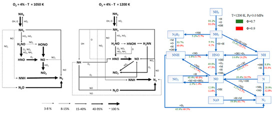
Figure 24.
The pathway of NOx formation under the influence of temperature with an equivalent air/fuel ratio (left); under the influence of the air/fuel ratio with equivalent pressure (right) [193,194].
Figure 25 shows the simulation results of the ammonia oxidation process, producing NO through two commonly used reaction mechanisms, Mei and CEU-NH3, under different combustion pressures. It can be seen from the figure that different reaction mechanism models correspond to different ammonia oxidation processes. In addition, all reactions involved in the oxidation of ammonia to NO gradually strengthen with the increase in combustion pressure, and the effect is significant.
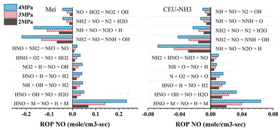
Figure 25.
NO formation pathways under the influence of combustion pressure for different mechanism models [36].
When burning an ammonia–hydrogen mixture, the mechanism of NOx generation with different energy ratios is shown in Figure 26. Changing the energy ratio of the mixed fuel not only affects the types of intermediate products but also affects the reaction pathways of different reactants. Among them, the newly added reactions are R178, R127, R173, R103, R123, R51, R50, and R105, and the more sensitive reactions were R20, R29, R53, and R49. When methane, DME, and traditional fuel are mixed with ammonia, their own products do not participate in the ammonia oxidation process. Therefore, when these fuels are mixed with ammonia, the actual influence is the ammonia oxidation reaction temperature and combustion chamber pressure, air/fuel ratio, energy ratio, etc. The influence of these factors on ammonia oxidation has been described above.
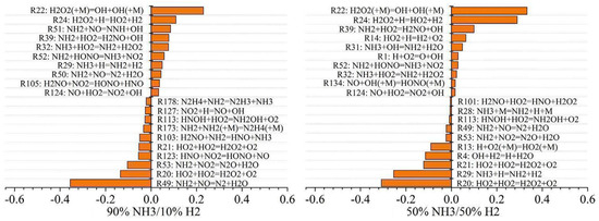
Figure 26.
The formation mechanism of NOx when burning an ammonia–hydrogen mixture with different energy ratios [195].
7. Conclusions
Based on the difference in the structure and working principle of different power equipment, this paper delves into the combustion and NOx emission characteristics of NH3 fuel in various power equipment, including SI, CI, and GT, from the perspectives of mixed fuel types and modes, structural design and operating strategies, and auxiliary combustion techniques. It also summarizes the current status of NH3-FC applications and elaborates on the different heat sources and NOx emissions associated with IA-PEMFCs.
With the comprehensive combination of mixed fuel, structural adjustment, auxiliary combustion, and other technologies, NH3 fuel can burn stably in ICE, and the power and NOx emissions are within the acceptable range. In addition to NH3/H2, NH3/CH4 and its mixture with gasoline can also be used in SI, NH3/DME and its mixture with diesel can also be used in CI, and NH3/CH4 and its mixture with kerosene can also be used in GT. Compared with CI, when SI uses a NH3/H2 mixture for combustion, due to the controllable CR and ignition energy, the amount of NH3 can be added in a wide range, while when NH3/H2 is used in GTs for combustion, the amount of NH3 added is not more than 55%. In addition, beyond 22% XNH3, a noticeable drop in combustion efficiency and thermal efficiency occurred, while the GT operated stably until XNH3 reached 63%.
Due to the high autogenous ignition temperature of NH3 fuel and the structural differences between SI and CI, the allowable CR of SI and CI are not more than 15 and 21.9, respectively. In addition, the combustion characteristics of NH3 fuel in SI can be improved by supercharging, increasing CR, prolonging ignition time, increasing the number of spark plugs, and other structure adjustment technologies, as well as the use of EGR, preheating, NH3 cracking, and other auxiliary combustion technologies. CI uses multiple fuel strategies and split diesel injection, while GT generally adopts structural strategies such as optimizing cyclones, non-premixed combustion, plasma discharge devices, and auxiliary combustion technologies such as rich lean combustion and secondary air supply.
Compared with DAFC systems, IAFC is the best option for train powertrains when considering storage space and fuel costs, but the high technology requirements of the purifier pose a challenge. Benefiting from the operating high temperature of DAFC, reducing the NH3 cracker and purifier of DAFC systems is still at the lab level.
Emission reduction technologies are mainly divided into SCR technology, staged combustion technology, and medium–low oxygen combustion technology. The research on SCR Technology is that the chemical adsorption of functional groups on the surface of carbon-based materials should be further studied due to the influence of other pollutants.
Funding
This study was supported by the Key Research and Development Project of Hubei Province (Grant No. 2022BID011) and the National Natural Science Foundation of China (Grant No. 51976235).
Acknowledgments
We gratefully acknowledge all the groups and individuals who have made outstanding contributions to this paper. We also extend our sincere gratitude to the editor for providing us with the opportunity to submit a revised version of our manuscript. We eagerly await the reviewers’ feedback, which will play a crucial role in shaping the future research direction of our group.
Conflicts of Interest
The authors declare no conflict of interest.
References
- WMO. Provisional State of the Global Climate in 2022; WMO: Geneva, Switzerland, 2022; Volume 26. [Google Scholar]
- International Renewable Energy Agency (IRENA). World Energy Transitions Outlook 2022; International Renewable Energy Agency: Abu Dhabi, United Arab Emirates, 2022. [Google Scholar]
- International Energy Agency. Net Zero by 2050: A Roadmap for the Global Energy Sector 2021; International Energy Agency: Paris, France, 2021; Volume 70. [Google Scholar]
- United Nations. SDGs Report 2023; United Nations: New York, NY, USA, 2023. [Google Scholar]
- Barnett, H. The European court of justice. In Constitutional & Administrative Law, 5th ed.; Routledge: London, UK, 2004. [Google Scholar] [CrossRef]
- IPCC. Strengthening and Implementing the Global Response; IPCC: Geneva, Switzerland, 2022. [Google Scholar] [CrossRef]
- IPCC. Impacts of 1.5 °C Global Warming on Natural and Human Systems; IPCC: Geneva, Switzerland, 2022. [Google Scholar] [CrossRef]
- Solomon, B.D. Energy carriers. In Dictionary of Ecological Economics: Terms for the New Millennium; Edward Elgar Publishing: Cheltenham, UK, 2023; p. 185. [Google Scholar] [CrossRef]
- Luo, Y.; Shi, Y.; Cai, N. Ammonia: A Clean and Efficient Energy Carrier for Distributed Hybrid System; Elsevier Inc.: Amsterdam, The Netherlands, 2021. [Google Scholar] [CrossRef]
- Lewis, J. Fuels without Carbon: Prospects and the Pathway Forward for Zero-Carbon Hydrogen and Ammonia Fuel; Ammonia Energy Association: Ashburn, VA, USA, 2018. [Google Scholar]
- Zamfirescu, C.; Dincer, I. Using ammonia as a sustainable fuel. J. Power Sources 2008, 185, 459–465. [Google Scholar] [CrossRef]
- By, I.; Vassiliadou, E.; Amirkhanian, S.N. Renewable Ammonia Generation, Transport, and Utilization in the Transportation Sector; Ammonia Energy Association: Ashburn, VA, USA, 2019; Volume 11, pp. 295–301. [Google Scholar]
- Faye, O.; Szpunar, J.; Eduok, U. A critical review on the current technologies for the generation, storage, and transportation of hydrogen. Int. J. Hydrogen Energy 2022, 47, 13771–13802. [Google Scholar] [CrossRef]
- Ezzat, M.F.; Dincer, I. Comparative assessments of two integrated systems with/without fuel cells utilizing liquefied ammonia as a fuel for vehicular applications. Int. J. Hydrogen Energy 2018, 43, 4597–4608. [Google Scholar] [CrossRef]
- Cui, J.; Aziz, M. Techno-economic analysis of hydrogen transportation infrastructure using ammonia and methanol. Int. J. Hydrogen Energy 2023, 48, 15737–15747. [Google Scholar] [CrossRef]
- Wang, W.; Herreros, J.M.; Tsolakis, A.; York, A.P.E. Ammonia as hydrogen carrier for transportation; Investigation of the ammonia exhaust gas fuel reforming. Int. J. Hydrogen Energy 2013, 38, 9907–9917. [Google Scholar] [CrossRef]
- Bartels, J.R. A Feasibility Study of Implementing an Ammonia Economy; Iowa State University: Ames, IA, USA, 2008; Volume 102. [Google Scholar]
- De Vries, N.; Okafor, E.C.; Gutesa-Bozo, M.; Xiao, H.; Valera-Medina, A. Use of Ammonia for Heat, Power and Propulsion; Elsevier Inc.: Amsterdam, The Netherlands, 2020. [Google Scholar] [CrossRef]
- Berwal, P.; Kumar, S.; Khandelwal, B. A comprehensive review on synthesis, chemical kinetics, and practical application of ammonia as future fuel for combustion. J. Energy Inst. 2021, 99, 273–298. [Google Scholar] [CrossRef]
- Olabi, A.; Abdelkareem, M.A.; Al-Murisi, M.; Shehata, N.; Alami, A.H.; Radwan, A.; Wilberforce, T.; Chae, K.-J.; Sayed, E.T. Recent progress in Green Ammonia: Production, applications, assessment; barriers, and its role in achieving the sustainable development goals. Energy Convers. Manag. 2023, 277, 116594. [Google Scholar] [CrossRef]
- MacFarlane, D.R.; Cherepanov, P.V.; Choi, J.; Suryanto, B.H.; Hodgetts, R.Y.; Bakker, J.M.; Vallana, F.M.F.; Simonov, A.N. A Roadmap to the Ammonia Economy. Joule 2020, 4, 1186–1205. [Google Scholar] [CrossRef]
- Valera-Medina, A.; Xiao, H.; Owen-Jones, M.; David, W.I.F.; Bowen, P.J. Ammonia for power. Prog. Energy Combust. Sci. 2018, 69, 63–102. [Google Scholar] [CrossRef]
- Egerer, J.; Grimm, V.; Niazmand, K.; Runge, P. The economics of global green ammonia trade “Shipping Australian wind and sunshine to Germany”. Appl. Energy 2023, 334, 120662. [Google Scholar] [CrossRef]
- Krishnamoorthi, M.; Malayalamurthi, R.; He, Z.; Kandasamy, S. A review on low temperature combustion engines: Performance, combustion and emission characteristics. Renew. Sustain. Energy Rev. 2019, 116, 109404. [Google Scholar] [CrossRef]
- Viggiano, A.; Magi, V. A Comprehensive Perspective on a Promising Fuel for Thermal Engines: Syngas and Its Surrogates; Elsevier Inc.: Amsterdam, The Netherlands, 2023. [Google Scholar] [CrossRef]
- Morlanés, N.; Katikaneni, S.P.; Paglieri, S.N.; Harale, A.; Solami, B.; Sarathy, S.M.; Gascon, J. A technological roadmap to the ammonia energy economy: Current state and missing technologies. Chem. Eng. J. 2021, 408, 127310. [Google Scholar] [CrossRef]
- Cornelius, W.; Huellmantel, L.W.; Mitchell, H.R. Ammonia as an Engine Fuel; SAE Technical Paper; SAE International: Warrendale, PA, USA, 1965. [Google Scholar] [CrossRef]
- Starkman, E.S.; James, G.E.; Newhall, H.K. Ammonia as a Diesel Engine Fuel: Theory and Application; SAE Technical Paper; SAE International: Warrendale, PA, USA, 1967. [Google Scholar] [CrossRef]
- Starkman, E.S.; Samuelsen, G.S. Flame-propagation rates in ammonia-air combustion at high pressure. Symp. Combust. 1967, 11, 1037–1045. [Google Scholar] [CrossRef][Green Version]
- Liu, Z.; Zhou, L.; Zhong, L.; Wei, H. Enhanced combustion of ammonia engine based on novel air-assisted pre-chamber turbulent jet ignition. Energy Convers. Manag. 2023, 276, 116526. [Google Scholar] [CrossRef]
- Grannell, S. The Operating Features of a Stoichiometric, Ammonia and Gasoline Dual Fueled Spark Ignition Engine. Ph.D. Thesis, University of Michigan, Ann Arbor, MI, USA, 2008. [Google Scholar]
- Wu, Y.; Zhang, Y.; Xia, C.; Chinnathambi, A.; Nasif, O.; Gavurová, B.; Sekar, M.; Anderson, A.; Chi, N.T.L.; Pugazhendhi, A. Assessing the effects of ammonia (NH3) as the secondary fuel on the combustion and emission characteristics with nano-additives. Fuel 2023, 336, 126831. [Google Scholar] [CrossRef]
- Li, T.; Duan, Y.; Wang, Y.; Zhou, M.; Duan, L. Research progress of ammonia combustion toward low carbon energy. Fuel Process. Technol. 2023, 248, 107821. [Google Scholar] [CrossRef]
- Li, H.; Xiao, H.; Sun, J. Laminar burning velocity, Markstein length, and cellular instability of spherically propagating NH3/H2/Air premixed flames at moderate pressures. Combust. Flame 2022, 241, 112079. [Google Scholar] [CrossRef]
- Cai, T.; Zhao, D.; Gutmark, E. Overview of fundamental kinetic mechanisms and emission mitigation in ammonia combustion. Chem. Eng. J. 2023, 458, 141391. [Google Scholar] [CrossRef]
- Liu, S.; Lin, Z.; Zhang, H.; Lei, N.; Qi, Y.; Wang, Z. Impact of ammonia addition on knock resistance and combustion performance in a gasoline engine with high compression ratio. Energy 2023, 262, 125458. [Google Scholar] [CrossRef]
- Westlye, F.R.; Ivarsson, A.; Schramm, J. Experimental investigation of nitrogen based emissions from an ammonia fueled SI-engine. Fuel 2013, 111, 239–247. [Google Scholar] [CrossRef]
- Kurien, C.; Mittal, M. Review on the production and utilization of green ammonia as an alternate fuel in dual-fuel compression ignition engines. Energy Convers. Manag. 2022, 251, 114990. [Google Scholar] [CrossRef]
- Wei, W.; Li, G.; Zhang, Z.; Long, Y.; Zhang, H.; Huang, Y.; Zhou, M.; Wei, Y. Effects of ammonia addition on the performance and emissions for a spark-ignition marine natural gas engine. Energy 2023, 272, 127092. [Google Scholar] [CrossRef]
- Zhang, R.; Chen, L.; Wei, H.; Li, J.; Chen, R.; Pan, J. Understanding the difference in combustion and flame propagation characteristics between ammonia and methane using an optical SI engine. Fuel 2022, 324, 124794. [Google Scholar] [CrossRef]
- Elbaz, A.M.; Wang, S.; Guiberti, T.F.; Roberts, W.L. Review on the recent advances on ammonia combustion from the fundamentals to the applications. Fuel Commun. 2022, 10, 100053. [Google Scholar] [CrossRef]
- Kurien, C.; Varma, P.S.; Mittal, M. Effect of ammonia energy fractions on combustion stability and engine characteristics of gaseous (ammonia/methane) fuelled spark ignition engine. Int. J. Hydrogen Energy 2023, 48, 1391–1400. [Google Scholar] [CrossRef]
- Huang, F.; Guo, S.; Wang, L.; Yang, Z.; Kong, W. Experimental and numerical study on the performances of a free-piston engine generator using ammonia and methane fuel mixtures. Fuel 2023, 341, 127654. [Google Scholar] [CrossRef]
- Oh, S.; Park, C.; Ahn, M.; Jang, H.J.; Kim, S. Experimental approach for reducing nitrogen oxides emissions from ammonia–natural gas dual-fuel spark-ignition engine. Fuel 2023, 332, 126065. [Google Scholar] [CrossRef]
- Oh, S.; Park, C.; Kim, S.; Kim, Y.; Choi, Y.; Kim, C. Natural gas–ammonia dual-fuel combustion in spark-ignited engine with various air–fuel ratios and split ratios of ammonia under part load condition. Fuel 2021, 290, 120095. [Google Scholar] [CrossRef]
- Mørch, C.S.; Bjerre, A.; Gøttrup, M.P.; Sorenson, S.C.; Schramm, J. Ammonia/hydrogen mixtures in an SI-engine: Engine performance and analysis of a proposed fuel system. Fuel 2011, 90, 854–864. [Google Scholar] [CrossRef]
- Zhang, J.; Luong, M.B.; Im, H.G. Detonation peninsula of different stoichiometric ammonia/hydrogen/air mixtures under engine-relevant conditions. Combust. Flame 2023, 253, 112793. [Google Scholar] [CrossRef]
- Li, J.; Zhang, R.; Pan, J.; Wei, H.; Shu, G.; Chen, L. Ammonia and hydrogen blending effects on combustion stabilities in optical SI engines. Energy Convers. Manag. 2023, 280, 116827. [Google Scholar] [CrossRef]
- Frigo, S.; Gentili, R. Analysis of the behaviour of a 4-stroke Si engine fuelled with ammonia and hydrogen. Int. J. Hydrogen Energy 2013, 38, 1607–1615. [Google Scholar] [CrossRef]
- Xin, G.; Ji, C.; Wang, S.; Hong, C.; Meng, H.; Yang, J. Experimental study on the effect of hydrogen substitution rate on combustion and emission characteristics of ammonia internal combustion engine under different excess air ratio. Fuel 2023, 343, 127992. [Google Scholar] [CrossRef]
- Lhuillier, C.; Brequigny, P.; Contino, F.; Mounaïm-Rousselle, C. Experimental study on ammonia/hydrogen/air combustion in spark ignition engine conditions. Fuel 2020, 269, 117448. [Google Scholar] [CrossRef]
- Lhuillier, C.; Brequigny, P.; Contino, F.; Mounaïm-Rousselle, C. Experimental investigation on ammonia combustion behavior in a spark-ignition engine by means of laminar and turbulent expanding flames. Proc. Combust. Inst. 2021, 38, 6671–6678. [Google Scholar] [CrossRef]
- Dinesh, M.H.; Pandey, J.K.; Kumar, G.N. Study of performance, combustion, and NOx emission behavior of an SI engine fuelled with ammonia/hydrogen blends at various compression ratio. Int. J. Hydrogen Energy 2022, 47, 25391–25403. [Google Scholar] [CrossRef]
- Elumalai, R.; Ravi, K. Strategy to reduce carbon emissions by adopting ammonia—Algal biodiesel in RCCI engine and optimize the fuel concoction using RSM methodology. Int. J. Hydrogen Energy 2022, 47, 39701–39718. [Google Scholar] [CrossRef]
- Chen, Y.; Zhang, B.; Su, Y.; Sui, C.; Zhang, J. Effect and mechanism of combustion enhancement and emission reduction for non-premixed pure ammonia combustion based on fuel preheating. Fuel 2022, 308, 9–11. [Google Scholar] [CrossRef]
- Ryu, K.; Zacharakis-Jutz, G.E.; Kong, S.C. Effects of gaseous ammonia direct injection on performance characteristics of a spark-ignition engine. Appl. Energy 2014, 116, 206–215. [Google Scholar] [CrossRef]
- Pandey, J.K.; Dinesh, M.H.; Kumar, G.N. A comparative study of NOx mitigating techniques EGR and spark delay on combustion and NOx emission of ammonia/hydrogen and hydrogen fuelled SI engine. Energy 2023, 276, 127611. [Google Scholar] [CrossRef]
- Xin, G.; Ji, C.; Wang, S.; Hong, C.; Meng, H.; Yang, J.; Su, F. Experimental study of the effect of variable valve timing on hydrogen-enriched ammonia engine. Fuel 2023, 344, 128131. [Google Scholar] [CrossRef]
- Xin, G.; Ji, C.; Wang, S.; Hong, C.; Meng, H.; Yang, J.; Su, F. Experimental study on the load control strategy of ammonia-hydrogen dual-fuel internal combustion engine for hybrid power system. Fuel 2023, 347, 128396. [Google Scholar] [CrossRef]
- Hong, C.; Ji, C.; Wang, S.; Xin, G.; Wang, Z.; Meng, H.; Yang, J. An experimental study of various load control strategies for an ammonia/hydrogen dual-fuel engine with the Miller cycle. Fuel Process. Technol. 2023, 247, 107780. [Google Scholar] [CrossRef]
- Wang, B.; Yang, C.; Wang, H.; Hu, D.; Duan, B.; Wang, Y. Study on injection strategy of ammonia/hydrogen dual fuel engine under different compression ratios. Fuel 2023, 334, 126666. [Google Scholar] [CrossRef]
- Pham, Q.; Park, S.; Agarwal, A.K.; Park, S. Review of dual-fuel combustion in the compression-ignition engine: Spray, combustion, and emission. Energy 2022, 250, 123778. [Google Scholar] [CrossRef]
- Kurien, C.; Mittal, M. Utilization of green ammonia as a hydrogen energy carrier for decarbonization in spark ignition engines. Int. J. Hydrogen Energy 2023, 48, 28803–28823. [Google Scholar] [CrossRef]
- Zhang, H.; Li, G.; Long, Y.; Zhang, Z.; Wei, W.; Zhou, M.; Belal, B.Y. Numerical study on combustion and emission characteristics of a spark-ignition ammonia engine added with hydrogen-rich gas from exhaust-fuel reforming. Fuel 2023, 332, 125939. [Google Scholar] [CrossRef]
- Raptotasios, S.I.; Sakellaridis, N.F.; Papagiannakis, R.G.; Hountalas, D.T. Application of a multi-zone combustion model to investigate the NOx reduction potential of two-stroke marine diesel engines using EGR. Appl. Energy 2015, 157, 814–823. [Google Scholar] [CrossRef]
- Ivanič, Ž.; Ayala, F.; Goldwitz, J.; Heywood, J.B. Effects of Hydrogen Enhancement on Efficiency and NOx Emissions of Lean and EGR-Diluted Mixtures in a SI Engine; SAE Technical Paper; SAE International: Warrendale, PA, USA, 2005. [Google Scholar] [CrossRef]
- Dhyani, V.; Subramanian, K.A. Control of backfire and NOx emission reduction in a hydrogen fueled multi-cylinder spark ignition engine using cooled EGR and water injection strategies. Int. J. Hydrogen Energy 2019, 44, 6287–6298. [Google Scholar] [CrossRef]
- Ezzat, M.F.; Dincer, I. Development and assessment of a new hybrid vehicle with ammonia and hydrogen. Appl. Energy 2018, 219, 226–239. [Google Scholar] [CrossRef]
- Uddeen, K.; Tang, Q.; Shi, H.; Magnotti, G.; Turner, J. A novel multiple spark ignition strategy to achieve pure ammonia combustion in an optical spark-ignition engine. Fuel 2023, 349, 128741. [Google Scholar] [CrossRef]
- Liu, Z.; Zhou, L.; Wei, H. Experimental investigation on the performance of pure ammonia engine based on reactivity controlled turbulent jet ignition. Fuel 2023, 335, 127116. [Google Scholar] [CrossRef]
- Koike, M.; Suzuoki, T.; Takeuchi, T.; Homma, T.; Hariu, S.; Takeuchi, Y. Cold-start performance of an ammonia-fueled spark ignition engine with an on-board fuel reformer. Int. J. Hydrogen Energy 2021, 46, 25689–25698. [Google Scholar] [CrossRef]
- Ryu, K.; Zacharakis-Jutz, G.E.; Kong, S.C. Performance enhancement of ammonia-fueled engine by using dissociation catalyst for hydrogen generation. Int. J. Hydrogen Energy 2014, 39, 2390–2398. [Google Scholar] [CrossRef]
- Comotti, M.; Frigo, S. Hydrogen generation system for ammonia-hydrogen fuelled internal combustion engines. Int. J. Hydrogen Energy 2015, 40, 10673–10686. [Google Scholar] [CrossRef]
- Oh, S.; Park, C.; Oh, J.; Kim, S.; Kim, Y.; Choi, Y.; Kim, C. Combustion, emissions, and performance of natural gas–ammonia dual-fuel spark-ignited engine at full-load condition. Energy 2022, 258, 124837. [Google Scholar] [CrossRef]
- Bermúdez, V.; Ruiz, S.; Sanchis, E.J.; Conde, B. Assessment of exhaust raw emissions and aftertreatment performance in a retrofitted heavy duty-spark ignition engine operating with liquefied petroleum gas. J. Clean. Prod. 2024, 434, 140139. [Google Scholar] [CrossRef]
- Prikhodko, V.Y.; Pihl, J.A.; Toops, T.J.; Thomas, C.R.; Parks, J.E. Effects of including a NOx storage component on a TWC when using a lean spark ignition gasoline engine combined with a passive SCR system. Appl. Energy Combust. Sci. 2023, 14, 100150. [Google Scholar] [CrossRef]
- Gainey, B.; Gohn, J.; Hariharan, D.; Rahimi-Boldaji, M.; Lawler, B. Assessing the impact of injector included angle and piston geometry on thermally stratified compression ignition with wet ethanol. Appl. Energy 2020, 262, 114528. [Google Scholar] [CrossRef]
- Xu, L.; Treacy, M.; Zhang, Y.; Aziz, A.; Tuner, M.; Bai, X.S. Comparison of efficiency and emission characteristics in a direct-injection compression ignition engine fuelled with iso-octane and methanol under low temperature combustion conditions. Appl. Energy 2022, 312, 118714. [Google Scholar] [CrossRef]
- Dimitriou, P.; Javaid, R. A review of ammonia as a compression ignition engine fuel. Int. J. Hydrogen Energy 2020, 45, 7098–7118. [Google Scholar] [CrossRef]
- Sun, W.; Zeng, W.; Guo, L.; Zhang, H.; Yan, Y.; Lin, S.; Zhu, G.; Jiang, M.; Yu, C.; Wu, F. An optical study of the combustion and flame development of ammonia-diesel dual-fuel engine based on flame chemiluminescence. Fuel 2023, 349, 128507. [Google Scholar] [CrossRef]
- Lu, Z.; Ye, J.; Gui, Y.; Lu, T.; Shi, L.; An, Y.; Wang, T. Numerical study of the compression ignition of ammonia in a two-stroke marine engine by using HTCGR strategy. Energy 2023, 276, 127578. [Google Scholar] [CrossRef]
- Yousefi, A.; Guo, H.; Dev, S.; Lafrance, S.; Liko, B. A study on split diesel injection on thermal efficiency and emissions of an ammonia/diesel dual-fuel engine. Fuel 2022, 316, 123412. [Google Scholar] [CrossRef]
- Liu, L.; Wu, Y.; Wang, Y. Numerical investigation on the combustion and emission characteristics of ammonia in a low-speed two-stroke marine engine. Fuel 2022, 314, 122727. [Google Scholar] [CrossRef]
- Reiter, A.J.; Kong, S.C. Combustion and emissions characteristics of compression-ignition engine using dual ammonia-diesel fuel. Fuel 2011, 90, 87–97. [Google Scholar] [CrossRef]
- Yousefi, A.; Guo, H.; Dev, S.; Liko, B.; Lafrance, S. Effects of ammonia energy fraction and diesel injection timing on combustion and emissions of an ammonia/diesel dual-fuel engine. Fuel 2022, 314, 122723. [Google Scholar] [CrossRef]
- Zhang, Z.; Long, W.; Dong, P.; Tian, H.; Tian, J.; Li, B.; Wang, Y. Performance characteristics of a two-stroke low speed engine applying ammonia/diesel dual direct injection strategy. Fuel 2023, 332, 126086. [Google Scholar] [CrossRef]
- Liu, L.; Wu, Y.; Wang, Y.; Wu, J.; Fu, S. Exploration of environmentally friendly marine power technology—Ammonia/diesel stratified injection. J. Clean. Prod. 2022, 380, 135014. [Google Scholar] [CrossRef]
- Zhou, X.; Li, T.; Wang, N.; Wang, X.; Chen, R.; Li, S. Pilot diesel-ignited ammonia dual fuel low-speed marine engines: A comparative analysis of ammonia premixed and high-pressure spray combustion modes with CFD simulation. Renew. Sustain. Energy Rev. 2023, 173, 113108. [Google Scholar] [CrossRef]
- Zhu, J.; Zhou, D.; Yang, W.; Qian, Y.; Mao, Y.; Lu, X. Investigation on the potential of using carbon-free ammonia in large two-stroke marine engines by dual-fuel combustion strategy. Energy 2023, 263, 125748. [Google Scholar] [CrossRef]
- Frost, J.; Tall, A.; Sheriff, A.M.; Schönborn, A.; Hellier, P. An experimental and modelling study of dual fuel aqueous ammonia and diesel combustion in a single cylinder compression ignition engine. Int. J. Hydrogen Energy 2021, 46, 35495–35510. [Google Scholar] [CrossRef]
- Al-Dawody, M.F.; Al-Obaidi, W.; Aboud, E.D.; Abdulwahid, M.A.; Al-Farhany, K.; Jamshed, W.; Eid, M.R.; Raizah, Z.; Iqbal, A. Mechanical engineering advantages of a dual fuel diesel engine powered by diesel and aqueous ammonia blends. Fuel 2023, 346, 128398. [Google Scholar] [CrossRef]
- Kuta, K.; Przybyła, G.; Kurzydym, D.; Żmudka, Z. Experimental and numerical investigation of dual-fuel CI ammonia engine emissions and after-treatment with V2O5/SiO2–TiO2 SCR. Fuel 2023, 334, 126523. [Google Scholar] [CrossRef]
- Şahin, Z.; Ziya Akcanca, İ.; Durgun, O. Experimental investigation of the effects of ammonia solution (NH3OH) on engine performance and exhaust emissions of a small diesel engine. Fuel 2018, 214, 330–341. [Google Scholar] [CrossRef]
- Lamas, M.I.; Rodriguez, C.G. Numerical model to analyze NOx reduction by ammonia injection in diesel-hydrogen engines. Int. J. Hydrogen Energy 2017, 42, 26132–26141. [Google Scholar] [CrossRef]
- Jin, Y.; Li, X.; Wang, X.; Ma, Z.; Chu, X. Effect of dimethyl ether on ignition characteristics of ammonia and chemical kinetics. Fuel 2023, 343, 127885. [Google Scholar] [CrossRef]
- Ryu, K.; Zacharakis-Jutz, G.E.; Kong, S.C. Performance characteristics of compression-ignition engine using high concentration of ammonia mixed with dimethyl ether. Appl. Energy 2014, 113, 488–499. [Google Scholar] [CrossRef]
- Pochet, M.; Jeanmart, H.; Contino, F. A 22:1 Compression Ratio Ammonia-Hydrogen HCCI Engine: Combustion, Load, and Emission Performances. Front. Mech. Eng. 2020, 6, 43. [Google Scholar] [CrossRef]
- Pochet, M.; Truedsson, I.; Foucher, F.; Contino, F.; Brussel, V.U. Ammonia-Hydrogen Blends in Homogeneous-Charge Compression-Ignition Engine; SAE Technical Paper No. 2017-24-0087; SAE International: Warrendale, PA, USA, 2017. [Google Scholar] [CrossRef]
- Wang, H.; Wang, B.; Yang, C.; Hu, D.; Duan, B.; Wang, Y. Study on dual injection strategy of diesel ignition ammonia/hydrogen mixture fuel engine. Fuel 2023, 348, 128526. [Google Scholar] [CrossRef]
- Wang, B.; Wang, H.; Duan, B.; Yang, C.; Hu, D.; Wang, Y. Effect of ammonia/hydrogen mixture ratio on engine combustion and emission performance at different inlet temperatures. Energy 2023, 272, 127110. [Google Scholar] [CrossRef]
- Wang, B.; Yang, C.; Wang, H.; Hu, D.; Wang, Y. Effect of Diesel-Ignited Ammonia/Hydrogen mixture fuel combustion on engine combustion and emission performance. Fuel 2023, 331, 125865. [Google Scholar] [CrossRef]
- Chiong, M.-C.; Chong, C.T.; Ng, J.-H.; Mashruk, S.; Chong, W.W.F.; Samiran, N.A.; Mong, G.R.; Valera-Medina, A. Advancements of combustion technologies in the ammonia-fuelled engines. Energy Convers. Manag. 2021, 244, 114460. [Google Scholar] [CrossRef]
- Gill, S.S.; Chatha, G.S.; Tsolakis, A.; Golunski, S.E.; York, A.P.E. Assessing the effects of partially decarbonising a diesel engine by co-fuelling with dissociated ammonia. Int. J. Hydrogen Energy 2012, 37, 6074–6083. [Google Scholar] [CrossRef]
- Arcoumanis, C.; Bae, C.; Crookes, R.; Kinoshita, E. The potential of di-methyl ether (DME) as an alternative fuel for compression-ignition engines: A review. Fuel 2008, 87, 1014–1030. [Google Scholar] [CrossRef]
- Chen, Z.; Qin, X.; Ju, Y.; Zhao, Z.; Chaos, M.; Dryer, F.L. High temperature ignition and combustion enhancement by dimethyl ether addition to methane-air mixtures. Proc. Combust. Inst. 2007, 31, 1215–1222. [Google Scholar] [CrossRef]
- Gross, C.W.; Kong, S.C. Performance characteristics of a compression-ignition engine using direct-injection ammonia-DME mixtures. Fuel 2013, 103, 1069–1079. [Google Scholar] [CrossRef]
- Bro, K.; Pedersen, P.S. Alternative Diesel Engine Fuels: An Experimental Investigation of Methanol, Ethanol, Methane and Ammonia in a D.I. Diesel Engine with Pilot Injection; SAE Technical Paper; SAE International: Warrendale, PA, USA, 1977. [Google Scholar] [CrossRef]
- Wang, Y.; Zhou, X.; Liu, L. Feasibility study of hydrogen jet flame ignition of ammonia fuel in marine low speed engine. Int. J. Hydrogen Energy 2023, 48, 327–336. [Google Scholar] [CrossRef]
- Spiteri, A.; Eggenschwiler, P.D.; Liao, Y.; Wigley, G.; Michalow-Mauke, K.A.; Elsener, M.; Kröcher, O.; Boulouchos, K. Comparative analysis on the performance of pressure and air-assisted urea injection for selective catalytic reduction of NOx. Fuel 2015, 161, 269–277. [Google Scholar] [CrossRef]
- Khristamto Aditya Wardana, M.; Lim, O. Investigation of ammonia homogenization and NOx reduction quantity by remodeling urea injector shapes in heavy-duty diesel engines. Appl. Energy 2022, 323, 119586. [Google Scholar] [CrossRef]
- Sung, Y.; Choi, M.; Park, T.; Choi, C.; Park, Y.; Choi, G. Synergistic effect of mixer and mixing chamber on flow mixing and NOx reduction in a marine urea-SCR system. Chem. Eng. Process. Process Intensif. 2020, 150, 107888. [Google Scholar] [CrossRef]
- Ko, A.; Woo, Y.; Jang, J.Y.; Jung, Y.; Pyo, Y.D.; Jo, H.; Lim, O.; Lee, Y.J. Availability of NH3 adsorption in vanadium-based SCR for reducing NOx emission and NH3 slip. J. Ind. Eng. Chem. 2019, 78, 433–439. [Google Scholar] [CrossRef]
- Kurata, O.; Iki, N.; Inoue, T.; Matsunuma, T.; Tsujimura, T.; Furutani, H.; Kawano, M.; Arai, K.; Okafor, E.C.; Hayakawa, A.; et al. Development of a wide range-operable, rich-lean low-NOx combustor for NH3 fuel gas-turbine power generation. Proc. Combust. Inst. 2019, 37, 4587–4595. [Google Scholar] [CrossRef]
- Verkamp, F.J.; Hardin, M.C.; Williams, J.R. Ammonia combustion properties and performance in gas-turbine burners. Symp. Combust. 1967, 11, 985–992. [Google Scholar] [CrossRef]
- Li, S.; Li, T.; Wang, N.; Zhou, X.; Chen, R.; Yi, P. An investigation on near-field and far-field characteristics of superheated ammonia spray. Fuel 2022, 324, 124683. [Google Scholar] [CrossRef]
- An, Z.; Xing, J.; Kurose, R. Numerical study on the phase change and spray characteristics of liquid ammonia flash spray. Fuel 2023, 345, 128229. [Google Scholar] [CrossRef]
- Kurata, O.; Iki, N.; Matsunuma, T.; Inoue, T.; Tsujimura, T.; Furutani, H.; Kobayashi, H.; Hayakawa, A. Performances and emission characteristics of NH3-air and NH3-CH4-air combustion gas-turbine power generations. Proc. Combust. Inst. 2017, 36, 3351–3359. [Google Scholar] [CrossRef]
- Zhang, M.; Wei, X.; Wang, J.; Huang, Z.; Tan, H. The blow-off and transient characteristics of co-firing ammonia/methane fuels in a swirl combustor. Proc. Combust. Inst. 2021, 38, 5859–5868. [Google Scholar] [CrossRef]
- Somarathne, K.D.K.A.; Okafor, E.C.; Hayakawa, A.; Kudo, T.; Kurata, O.; Iki, N.; Kobayashi, H. Emission characteristics of turbulent non-premixed ammonia/air and methane/air swirl flames through a rich-lean combustor under various wall thermal boundary conditions at high pressure. Combust. Flame 2019, 210, 247–261. [Google Scholar] [CrossRef]
- Okafor, E.C.; Kurata, O.; Yamashita, H.; Inoue, T.; Tsujimura, T.; Iki, N.; Hayakawa, A.; Ito, S.; Uchida, M.; Kobayashi, H. Liquid ammonia spray combustion in two-stage micro gas turbine combustors at 0.25 MPa; Relevance of combustion enhancement to flame stability and NOx control. Appl. Energy Combust. Sci. 2021, 7, 100038. [Google Scholar] [CrossRef]
- Okafor, E.C.; Yamashita, H.; Hayakawa, A.; Somarathne, K.K.A.; Kudo, T.; Tsujimura, T.; Uchida, M.; Ito, S.; Kobayashi, H. Flame stability and emissions characteristics of liquid ammonia spray co-fired with methane in a single stage swirl combustor. Fuel 2021, 287, 119433. [Google Scholar] [CrossRef]
- Somarathne, K.D.K.A.; Hatakeyama, S.; Hayakawa, A.; Kobayashi, H. Numerical study of a low emission gas turbine like combustor for turbulent ammonia/air premixed swirl flames with a secondary air injection at high pressure. Int. J. Hydrogen Energy 2017, 42, 27388–27399. [Google Scholar] [CrossRef]
- Zhang, M.; An, Z.; Wang, L.; Wei, X.; Jianayihan, B.; Wang, J.; Huang, Z.; Tan, H. The regulation effect of methane and hydrogen on the emission characteristics of ammonia/air combustion in a model combustor. Int. J. Hydrogen Energy 2021, 46, 21013–21025. [Google Scholar] [CrossRef]
- Viswamithra, V.; Gurunadhan, M.; Menon, S. Expanding swirl combustor operability on methane-ammonia-air mixtures using a distributed fuel injection technique and inlet air preheating. Int. J. Hydrogen Energy 2023, 48, 1189–1201. [Google Scholar] [CrossRef]
- Mikulčić, H.; Baleta, J.; Wang, X.; Wang, J.; Qi, F.; Wang, F. Numerical simulation of ammonia/methane/air combustion using reduced chemical kinetics models. Int. J. Hydrogen Energy 2021, 46, 23548–23563. [Google Scholar] [CrossRef]
- Khateeb, A.A.; Guiberti, T.F.; Zhu, X.; Younes, M.; Jamal, A.; Roberts, W.L. Stability limits and NO emissions of technically-premixed ammonia-hydrogen-nitrogen-air swirl flames. Int. J. Hydrogen Energy 2020, 45, 22008–22018. [Google Scholar] [CrossRef]
- Wei, X.; Zhang, M.; Wang, J.; Huang, Z. Investigation on lean blow-off characteristics and stabilization mechanism of premixed hydrogen enhanced ammonia/air swirl flames in a gas turbine combustor. Combust. Flame 2023, 249, 112600. [Google Scholar] [CrossRef]
- Valera-Medina, A.; Gutesa, M.; Xiao, H.; Pugh, D.; Giles, A.; Goktepe, B.; Marsh, R.; Bowen, P. Premixed ammonia/hydrogen swirl combustion under rich fuel conditions for gas turbines operation. Int. J. Hydrogen Energy 2019, 44, 8615–8626. [Google Scholar] [CrossRef]
- Okafor, E.C.; Somarathne, K.K.A.; Hayakawa, A.; Kudo, T.; Kurata, O.; Iki, N.; Kobayashi, H. Towards the development of an efficient low-NOx ammonia combustor for a micro gas turbine. Proc. Combust. Inst. 2019, 37, 4597–4606. [Google Scholar] [CrossRef]
- Guteša Božo, M.; Mashruk, S.; Zitouni, S.; Valera-Medina, A. Humidified ammonia/hydrogen RQL combustion in a trigeneration gas turbine cycle. Energy Convers. Manag. 2021, 227, 113625. [Google Scholar] [CrossRef]
- Li, S.; Zhang, S.; Zhou, H.; Ren, Z. Analysis of air-staged combustion of NH3/CH4 mixture with low NOx emission at gas turbine conditions in model combustors. Fuel 2019, 237, 50–59. [Google Scholar] [CrossRef]
- Xiao, H.; Valera-Medina, A.; Marsh, R.; Bowen, P.J. Numerical study assessing various ammonia/methane reaction models for use under gas turbine conditions. Fuel 2017, 196, 344–351. [Google Scholar] [CrossRef]
- Ariemma, G.B.; Sorrentino, G.; Ragucci, R.; de Joannon, M.; Sabia, P. Ammonia/Methane combustion: Stability and NOx emissions. Combust. Flame 2022, 241, 112071. [Google Scholar] [CrossRef]
- Wu, Z.; Lv, J.; Liu, X.; Wu, W.; Zhou, S.; Yan, B.; Chen, G. Adiabatic laminar burning velocities and NO generation paths of NH3/H2 premixed flames. J. Energy Inst. 2023, 108, 101225. [Google Scholar] [CrossRef]
- Guteša Božo, M.; Vigueras-Zuniga, M.O.; Buffi, M.; Seljak, T.; Valera-Medina, A. Fuel rich ammonia-hydrogen injection for humidified gas turbines. Appl. Energy 2019, 251. [Google Scholar] [CrossRef]
- Okafor, E.C.; Somarathne, K.K.A.; Ratthanan, R.; Hayakawa, A.; Kudo, T.; Kurata, O.; Iki, N.; Tsujimura, T.; Furutani, H.; Kobayashi, H. Control of NOx and other emissions in micro gas turbine combustors fuelled with mixtures of methane and ammonia. Combust. Flame 2020, 211, 406–416. [Google Scholar] [CrossRef]
- Cai, Z.; Huang, M.; Wei, G.; Liu, Z.; Fang, H.; Song, Y.; Zhang, M.; Wang, W.; Ming, Z.; Wang, J.; et al. Numerical study of the effect of pressure on the combustion characteristics of ammonia/coal-derived syngas mixture under gas turbine operating conditions. Fuel 2023, 347, 128463. [Google Scholar] [CrossRef]
- Somarathne, K.D.K.A.; Okafor, E.C.; Sugawara, D.; Hayakawa, A.; Kobayashi, H. Effects of OH concentration and temperature on NO emission characteristics of turbulent non-premixed CH4/NH3/air flames in a two-stage gas turbine like combustor at high pressure. Proc. Combust. Inst. 2021, 38, 5163–5170. [Google Scholar] [CrossRef]
- Tang, Y.; Xie, D.; Shi, B.; Wang, N.; Li, S. Flammability enhancement of swirling ammonia/air combustion using AC powered gliding arc discharges. Fuel 2022, 313, 122674. [Google Scholar] [CrossRef]
- Vijrumbana, Y.; Singh, A.S.; Vakamalla, T.R.; Mahendra Reddy, V. A chemical kinetic analysis: Influence of post-flame chemistry, combustion pressure, premixing degree (fully premixed to non-premixed), and secondary air supply on NOx emissions from NH3/CH4-air combustion. Therm. Sci. Eng. Prog. 2023, 40, 101750. [Google Scholar] [CrossRef]
- Shahsavari, M.; Konnov, A.A.; Bai, X.S.; Valera-Medina, A.; Li, T.; Jangi, M. Synergistic effects of nanosecond plasma discharge and hydrogen on ammonia combustion. Fuel 2023, 348, 128475. [Google Scholar] [CrossRef]
- Belal, B.Y.; Li, G.; Zhang, Z.; El-Batsh, H.M.; Moneib, H.A.; Attia, A.M.A. The effect of swirl burner design configuration on combustion and emission characteristics of lean pre-vaporized premixed flames. Energy 2021, 228, 120622. [Google Scholar] [CrossRef]
- Mashruk, S.; Okafor, E.; Kovaleva, M.; Alnasif, A.; Pugh, D.; Hayakawa, A.; Valera-Medina, A. Evolution of N2O production at lean combustion condition in NH3/H2/air premixed swirling flames. Combust. Flame 2022, 244, 112299. [Google Scholar] [CrossRef]
- Ouyang, W.; Zheng, S.; Wu, C.; Hu, X.; Chen, R.; Zhuo, L.; Wang, Z. Dynamic ammonia adsorption by FAU zeolites to below 0.1 ppm for hydrogen energy applications. Int. J. Hydrogen Energy 2021, 46, 32559–32569. [Google Scholar] [CrossRef]
- Dincer, I.; Siddiqui, O. Types of fuels. In Ammonia Fuel Cells; Elsevier: Amsterdam, The Netherlands, 2020. [Google Scholar] [CrossRef]
- Dincer, I.; Siddiqui, O. Ammonia fuel cells. In Ammonia Fuel Cells; Elsevier: Amsterdam, The Netherlands, 2020; Volume 4. [Google Scholar] [CrossRef]
- Hu, J.; Liang, Q.; He, X.; Xia, S.; Liu, Y. Bio-inspired design of a fence-type triangular flow channel for ammonia-hydrogen fuel cells. Int. J. Hydrogen Energy 2023, 52, 799–815. [Google Scholar] [CrossRef]
- Ye, M.; Sharp, P.; Brandon, N.; Kucernak, A. System-level comparison of ammonia, compressed and liquid hydrogen as fuels for polymer electrolyte fuel cell powered shipping. Int. J. Hydrogen Energy 2022, 47, 8565–8584. [Google Scholar] [CrossRef]
- Zhong, C.; Hu, W.B.; Cheng, Y.F. Recent advances in electrocatalysts for electro-oxidation of ammonia. J. Mater. Chem. A 2013, 1, 3216–3238. [Google Scholar] [CrossRef]
- El-Shafie, M.; Kambara, S.; Hayakawa, Y. Development of zeolite-based catalyst for enhancement hydrogen production from ammonia decomposition. Catal. Today 2022, 397–399, 103–112. [Google Scholar] [CrossRef]
- Wang, Z.; Zhang, H.; Ye, Z.; He, G.; Liao, C.; Deng, J.; Lei, G.; Zheng, G.; Zhang, K.; Gou, F.; et al. H2 production from ammonia decomposition with Mo2N catalyst driven by dielectric barrier discharge plasma. Int. J. Hydrogen Energy 2023, 49, 1375–1385. [Google Scholar] [CrossRef]
- Armenise, S.; Cazaña, F.; Monzón, A.; García-Bordejé, E. In situ generation of COx-free H2 by catalytic ammonia decomposition over Ru-Al-monoliths. Fuel 2018, 233, 851–859. [Google Scholar] [CrossRef]
- Seyfeli, R.C.; Varisli, D. Performance of microwave reactor system in decomposition of ammonia using nickel based catalysts with different supports. Int. J. Hydrogen Energy 2022, 47, 15175–15188. [Google Scholar] [CrossRef]
- Wang, X.; Zhang, Z.; Zhou, G.; Zhang, Y.; Zhao, X.; Han, D.; Chen, T.; Huang, Z.; Lin, H. Synergistic effect between electric field and Ce-doped catalysts to promote hydrogen production from ammonia decomposition. Fuel 2023, 351, 128796. [Google Scholar] [CrossRef]
- Noskov, A.; Zolotarskii, I.; Pokrovskaya, S.; Kashkin, V.; Slavinskaya, E.; Mokrinskii, V.; Korotkikh, V. Ammonia oxidation into nitrous oxide over Mn/Bi/Al catalyst: II. Fluidized bed reactor experiments. Chem. Eng. J. 2005, 107, 79–87. [Google Scholar] [CrossRef]
- Warner, M.; Haynes, B.S. Formation of N2 and N2O in industrial combustion of ammonia over platinum. Proc. Combust. Inst. 2015, 35, 2215–2222. [Google Scholar] [CrossRef]
- Chiuta, S.; Everson, R.C.; Neomagus, H.W.J.P.; Bessarabov, D.G. Hydrogen production from ammonia decomposition over a commercial Ru/Al2O3 catalyst in a microchannel reactor: Experimental validation and CFD simulation. Int. J. Hydrogen Energy 2016, 41, 3774–3785. [Google Scholar] [CrossRef]
- Vernikovskaya, N.V.; Pinaeva, L.G.; Isupova, L.A. Oxidation of ammonia to NOx in a two bed reactor (Pt gauzes+oxide monolytic layer): Experimental studies and mathematical modelling. Chem. Eng. J. 2014, 238, 140–147. [Google Scholar] [CrossRef]
- Chiuta, S.; Bessarabov, D.G. Design and operation of an ammonia-fueled microchannel reactor for autothermal hydrogen production. Catal. Today 2018, 310, 187–194. [Google Scholar] [CrossRef]
- He, X.; Liu, Z.; Jiang, H.; Yang, Q.; Jiang, Z.; Feng, G.; Zhao, C. Super adiabatic flame temperature phenomenon for NH3/O2/N2 mixtures. Fuel 2023, 346, 128264. [Google Scholar] [CrossRef]
- Ilbas, M.; Kekul, O.; Bektas, A.; Karyeyen, S. Oxidizer effects on ammonia combustion using a generated non-premixed burner. Int. J. Hydrogen Energy 2022, 47, 12317–12337. [Google Scholar] [CrossRef]
- Yang, W.; Ranga Dinesh, K.K.J.; Luo, K.H.; Thevenin, D. Direct numerical simulation of turbulent premixed ammonia and ammonia-hydrogen combustion under engine-relevant conditions. Int. J. Hydrogen Energy 2022, 47, 11083–11100. [Google Scholar] [CrossRef]
- Scharl, V.; Lackovic, T.; Sattelmayer, T. Characterization of ammonia spray combustion and mixture formation under high-pressure, direct injection conditions. Fuel 2023, 333, 126454. [Google Scholar] [CrossRef]
- Zhu, S.; Xu, Q.; Tang, R.; Gao, J.; Wang, Z.; Pan, J.; Zhang, D. A comparative study of oxidation of pure ammonia and ammonia/dimethyl ether mixtures in a jet-stirred reactor using SVUV-PIMS. Combust. Flame 2023, 250, 112643. [Google Scholar] [CrossRef]
- Ju, R.; Wang, J.; Zhang, M.; Mu, H.; Zhang, G.; Yu, J.; Huang, Z. Stability and emission characteristics of ammonia/air premixed swirling flames with rotating gliding arc discharge plasma. Energy 2023, 277, 127649. [Google Scholar] [CrossRef]
- Vijrumbana, Y.; Shankar Singh, A.; Jik Lee, B.; Mahendra Reddy, V. Chemical kinetic analysis to study the potential of fuel staging in reducing the emissions from NH3/CH4-air combustion at different pressures. Fuel 2023, 339, 127404. [Google Scholar] [CrossRef]
- Mashruk, S.; Kovaleva, M.; Alnasif, A.; Chong, C.T.; Hayakawa, A.; Okafor, E.C.; Valera-Medina, A. Nitrogen oxide emissions analyses in ammonia/hydrogen/air premixed swirling flames. Energy 2022, 260, 125183. [Google Scholar] [CrossRef]
- Tomidokoro, T.; Yokomori, T.; Im, H.G. Numerical study on propagation and NO reduction behavior of laminar stratified ammonia/air flames. Combust. Flame 2022, 241, 112102. [Google Scholar] [CrossRef]
- Bykov, V.; Stein, M.; Maas, U. Study of mechanism of ammonia decomposition and oxidation: From NOx reduction to ammonia auto-ignition problem. Proc. Combust. Inst. 2023, 39, 4267–4275. [Google Scholar] [CrossRef]
- Yu, J.; Jiang, Z.; Hou, M.; Liang, D.; Xiao, Y.; Dou, M.; Shao, Z.; Yi, B. Analysis of the behavior and degradation in proton exchange membrane fuel cells with a dead-ended anode. J. Power Sources 2014, 246, 90–94. [Google Scholar] [CrossRef]
- Siegel, J.B.; Bohac, S.V.; Stefanopoulou, A.G.; Yesilyurt, S. Nitrogen Front Evolution in Purged Polymer Electrolyte Membrane Fuel Cell with Dead-Ended Anode. J. Electrochem. Soc. 2010, 157, B1081. [Google Scholar] [CrossRef]
- Du, Z.; Liu, C.; Zhai, J.; Guo, X.; Xiong, Y.; Su, W.; He, G. A review of hydrogen purification technologies for fuel cell vehicles. Catalysts 2021, 11, 393. [Google Scholar] [CrossRef]
- Lin, L.; Tian, Y.; Su, W.; Luo, Y.; Chen, C.; Jiang, L. Techno-economic analysis and comprehensive optimization of an on-site hydrogen refuelling station system using ammonia: Hybrid hydrogen purification with both high H2 purity and high recovery. Sustain. Energy Fuels 2020, 4, 3006–3017. [Google Scholar] [CrossRef]
- Patki, N.S.; Lundin, S.T.B.; Way, J.D. Apparent activation energy for hydrogen permeation and its relation to the composition of homogeneous PdAu alloy thin-film membranes. Sep. Purif. Technol. 2018, 191, 370–374. [Google Scholar] [CrossRef]
- Zhang, Z.; Liguori, S.; Fuerst, T.F.; Way, J.D.; Wolden, C.A. Efficient Ammonia Decomposition in a Catalytic Membrane Reactor to Enable Hydrogen Storage and Utilization. ACS Sustain. Chem. Eng. 2019, 7, 5975–5985. [Google Scholar] [CrossRef]
- Cechetto, V.; Struijk, C.L.; Di Felice, L.; de Leeuw den Bouter, A.W.N.; Gallucci, F. Adsorbents development for hydrogen cleanup from ammonia decomposition in a catalytic membrane reactor. Chem. Eng. J. 2023, 455, 140762. [Google Scholar] [CrossRef]
- Cerrillo, J.L.; Morlanés, N.; Kulkarni, S.R.; Realpe, N.; Ramírez, A.; Katikaneni, S.P.; Paglieri, S.N.; Lee, K.; Harale, A.; Solami, B.; et al. High purity, self-sustained, pressurized hydrogen production from ammonia in a catalytic membrane reactor. Chem. Eng. J. 2022, 431, 134310. [Google Scholar] [CrossRef]
- Makhloufi, C.; Kezibri, N. Large-scale decomposition of green ammonia for pure hydrogen production. Int. J. Hydrogen Energy 2021, 46, 34777–34787. [Google Scholar] [CrossRef]
- Zhao, J.F.; Liang, Y.F.; Liang, Q.C.; Li, M.J.; Hu, J.Y. Experimental and Simulation Study of PEMFC based on Ammonia Decomposition Gas as Fuel. J. Electrochem. Sci. Technol. 2022, 13, 63–70. [Google Scholar] [CrossRef]
- Zhao, Y.; Setzler, B.P.; Wang, J.; Nash, J.; Wang, T.; Xu, B.; Yan, Y. An Efficient Direct Ammonia Fuel Cell for Affordable Carbon-Neutral Transportation. Joule 2019, 3, 2472–2484. [Google Scholar] [CrossRef]
- Hu, J.; Liang, Q.; Li, M.; He, X.; Zhao, J.; Liu, Z.; Xia, S. Numerical simulation of gas–heat–water distribution characteristics of Ammonia–Hydrogen fuel cell. Energy Rep. 2022, 8, 9787–9804. [Google Scholar] [CrossRef]
- Hunter, H.M.; Makepeace, J.W.; Wood, T.J.; Mylius, O.S.; Kibble, M.G.; Nutter, J.B.; Jones, M.O.; David, W.I. Demonstrating hydrogen production from ammonia using lithium imide—Powering a small proton exchange membrane fuel cell. J. Power Sources 2016, 329, 138–147. [Google Scholar] [CrossRef]
- Lin, L.; Zhang, L.; Luo, Y.; Luo, J.; Chen, C.; Jiang, L. Highly-integrated and Cost-efficient Ammonia-fueled fuel cell system for efficient power generation: A comprehensive system optimization and Techno-Economic analysis. Energy Convers. Manag. 2022, 251, 114917. [Google Scholar] [CrossRef]
- Zhao, J.; Liang, Q.; Liang, Y.; Hu, J. Experimental and 3D simulation study of a nitrogen-hydrogen fueled PEMFC. Int. J. Electrochem. Sci. 2022, 17, 220313. [Google Scholar] [CrossRef]
- Woo, M.; Choi, B.C. Numerical study on fuel-NO formation characteristics of ammonia-added methane fuel in laminar non-premixed flames with oxygen/carbon dioxide oxidizer. Energy 2021, 226, 120365. [Google Scholar] [CrossRef]
- Cai, T.; Zhao, D.; Wang, B.; Li, J.; Guan, Y. NOx emission and thermal performances studies on premixed ammonia-oxygen combustion in a CO2-free micro-planar combustor. Fuel 2020, 280, 118554. [Google Scholar] [CrossRef]
- Ilbas, M.; Alemu, M.A.; Cimen, F.M. Comparative performance analysis of a direct ammonia-fuelled anode supported flat tubular solid oxide fuel cell: A 3D numerical study. Int. J. Hydrogen Energy 2022, 47, 3416–3428. [Google Scholar] [CrossRef]
- Feng, G.; Chen, J.; Fan, W.; Wang, X. Study of the interaction between NH3 and NO in the reduction zone of air-staged ammonia combustion under high moisture atmosphere. J. Clean. Prod. 2023, 409, 137218. [Google Scholar] [CrossRef]
- Sun, Z.; Xu, J.; Su, S.; Qing, M.; Wang, L.; Cui, X.; Mostafa, M.E.; Zhang, C.; Hu, S.; Wang, Y.; et al. Formation and reduction of NO from the oxidation of NH3/CH4 with high concentration of H2O. Fuel 2019, 247, 19–25. [Google Scholar] [CrossRef]
- Choe, J.; Sun, W.; Ombrello, T.; Carter, C. Plasma assisted ammonia combustion: Simultaneous NOx reduction and flame enhancement. Combust. Flame 2021, 228, 430–432. [Google Scholar] [CrossRef]
- Wickham, D.T.; Lind, J. Catalysts for the Selective Oxidation of Ammonia to Nitrogen and Water; SAE Technical Paper; SAE International: Warrendale, PA, USA, 2003. [Google Scholar] [CrossRef]
- Engelbrecht, N.; Chiuta, S.; Bessarabov, D.G. A highly efficient autothermal microchannel reactor for ammonia decomposition: Analysis of hydrogen production in transient and steady-state regimes. J. Power Sources 2018, 386, 47–55. [Google Scholar] [CrossRef]
- Stagni, A.; Cavallotti, C.; Arunthanayothin, S.; Song, Y.; Herbinet, O.; Battin-Leclerc, F.; Faravelli, T. An experimental, theoretical and kinetic-modeling study of the gas-phase oxidation of ammonia. React. Chem. Eng. 2020, 5, 696–711. [Google Scholar] [CrossRef]
- Meng, X.; Zhao, C.; Cui, Z.; Zhang, X.; Zhang, M.; Tian, J.; Long, W.; Bi, M. Understanding of combustion characteristics and NO generation process with pure ammonia in the pre-chamber jet-induced ignition system. Fuel 2023, 331, 125743. [Google Scholar] [CrossRef]
- Wang, Y.; Zhou, X.; Liu, L. Study on the mechanism of the ignition process of ammonia/hydrogen mixture under high-pressure direct-injection engine conditions. Int. J. Hydrogen Energy 2021, 46, 38871–38886. [Google Scholar] [CrossRef]
Disclaimer/Publisher’s Note: The statements, opinions and data contained in all publications are solely those of the individual author(s) and contributor(s) and not of MDPI and/or the editor(s). MDPI and/or the editor(s) disclaim responsibility for any injury to people or property resulting from any ideas, methods, instructions or products referred to in the content. |
© 2024 by the authors. Licensee MDPI, Basel, Switzerland. This article is an open access article distributed under the terms and conditions of the Creative Commons Attribution (CC BY) license (https://creativecommons.org/licenses/by/4.0/).