Article

Development and Implementation of a Smart Charging System for Electric Vehicles Based on the ISO 15118 Standard

by
Jóni B. Santos
1,*,
André M. B. Francisco
2,
Cristiano Cabrita
2,3,
Jânio Monteiro
2,3,*,
André Pacheco
1 and
Pedro J. S. Cardoso
3,4
1
Centre for Marine and Environmental Research—CIMA, Universidade do Algarve, 8005-139 Faro, Portugal
2
Centro de Investigação em Sistemas Ciberfísicos do Algarve—CISCA, Universidade do Algarve, 8005-139 Faro, Portugal
3
Instituto Superior de Engenharia, Universidade do Algarve, 8005-139 Faro, Portugal
4
NOVA LINCS, Universidade do Algarve, 8005-139 Faro, Portugal
*
Authors to whom correspondence should be addressed.
Energies 2024, 17(12), 3045; https://doi.org/10.3390/en17123045
Submission received: 30 April 2024 / Revised: 11 June 2024 / Accepted: 17 June 2024 / Published: 20 June 2024

Abstract

:
There is currently exponential growth in the electric vehicle market, which will require an increase in the electrical grid capacity to meet the associated charging demand. If, on the one hand, the introduction of energy generation from renewable energy sources can be used to meet that requirement, the intermittent nature of some of these sources will challenge the mandatory real-time equilibrium between generation and consumption. In order to use most of the energy generated via these sources, mechanisms are required to manage the charging of batteries in electric vehicles, according to the levels of generation. An effective smart charging process requires communication and/or control mechanisms between the supply equipment and the electric vehicle, enabling the adjustment of the energy transfer according to the generation levels. At this level, the ISO 15118 standard supports high-level communication mechanisms, far beyond the basic control solutions offered through the IEC 61851-1 specification. It is, thus, relevant to evaluate it in smart charging scenarios. In this context, this paper presents the development of a charge emulation system using the ISO 15118 communication protocol, and it discusses its application for demand response purposes. The system comprises several modules developed at both ends, supply equipment and electric vehicles, and allows the exchange of data during an emulated charging process. The system also includes human interfaces to facilitate interactions with users at both ends. Tests performed using the implemented system have shown that it supports a demand response when integrated with a photovoltaic renewable energy source. The dynamic adjustment to charging parameters, based on real-time energy availability, ensures efficient and sustainable charging processes, reducing the reliance on the grid and promoting the use of renewable energy.

1. Introduction

Introduced as a clean energy initiative due to their CO2 emissions (relatively low or null) [1], electric vehicles (EVs) support a new paradigm of sustainable mobility. At a global level, taking into account the average carbon emissions used for electricity generation (518 g of carbon dioxide equivalent per kilowatt-hour [518 g CO2-eq/kWh]) [2], an EV emits a smaller amount of greenhouse gases when compared with the average internal combustion vehicles. In 2023, the total number of EVs on the roads reached 40 million globally [3]; however, the uncontrolled charging requirements of this growing fleet represent a major challenge for the electrical grid, especially if the charging demand from EVs coincides with the peak consumption periods already existing in the grid, which can lead to its overload [4,5,6].
The two main solutions to this challenge could be, on the one hand, to introduce renewable energy sources (RESs), and particularly those that are generated at the distribution level, reducing the need for conventional energy sources, and, on the other hand, the introduction of demand response mechanisms that allow for adjusting the charging power of EVs according to the power output from these RESs. Through this mechanism, known as smart charging, EVs can minimize the requirements they place on electrical grids by shaping their demand pattern, varying their power intensity and charging periods [4,5,6]. At this level, EVs can be thought of as additional storage units either for the sole purpose of mobility or to support vehicle-to-grid (V2G) energy transfers [2]. In both cases, interoperability mechanisms between an EV and electric vehicle supply equipment (EVSE) are needed. One of the challenges associated with the implementation of grid-to-vehicle and V2G energy transfers is the limited capacity for exchanging information between the EV and the EVSE. Currently, most of this information exchange is performed via low-level control mechanisms (IEC 61851-1 [7]), through the control pilot and proximity pilot-signaling pins. Mostly used in the alternating current (AC) power transfer mode, the signaling carried out through these pins only indicates when the EV is connected to the EVSE and what the available electrical current that the supply equipment can supply to the vehicle is. That reduced set of control options limits the implementation of smart charging solutions [1,5,6].
In order to optimize charge management, improved interoperability between the EVSE and the EV is necessary. Information such as the state of charge (SoC) and its power limits are crucial to performing charge scheduling. Thus, there is a clear need for bidirectional communication between them, much beyond the control-level solutions offered through the IEC 61851-1 standard.
In this context, this work describes the development of a system that emulates a charging process between an EV and EVSE, and it uses the ISO 15118 [8] digital communication protocol. Its development required a comprehensive analysis of the ISO 15118 protocol, culminating in the design and implementation of the charging emulation system. Key steps included the following: (1) the characterization of system parameters; (2) architectural design; and (3) the development of human–machine interfaces (HMIs) for both EVs and EVSE (these interfaces play an important role in the process of demonstrating the system implemented). Two microcomputers were used to implement the communication between the Supply Equipment Communication Controller (SECC) and the Electric Vehicle Communication Controller (EVCC). Communication controllers were implemented to establish dynamic communication sessions, and they were developed using the open-source library RISE V2G [9]. Each controller (at the EVSE and EV) implemented a specific program/mechanism that managed a charge emulation process, while task-scheduling algorithms ensured a synchronized information exchange between EVs and the EVSE.
The system’s performance was validated through the testing of the emulator when applying charging techniques. The results show that it realistically approximates the behavior of an actual direct-current (DC) charging process. Also, tests were performed to evaluate its adaptability to varying levels of power, such as those that occur in demand response scenarios. These tests, using data from a photovoltaic generation unit, show that the system reacts quickly to power changes from intermittent photovoltaic generation, resulting in a low percentual mismatch between generation power and charging power.
The rest of this work is structured as follows. Section 2 describes the state of the art, including the ISO 15118 standard and the RISE V2G library. In Section 3, a description is provided of the development of the charging emulator system, including its characterization, architecture, and task-scheduling algorithms. Section 4 presents the obtained system and an evaluation. Finally, Section 5 concludes this work, discussing future developments.

2. State of the Art

The increasing adoption of EVs presents a challenge to electrical grids due to the surge in demand that occurs during charging times. While RESs can offer a sustainable solution, their intermittent nature requires a method to balance grid load with generation. Smart charging, which benefits from communication mechanisms between EVs and charging stations, is a promising approach to optimizing energy consumption and integrating EVs seamlessly into the grid. The ISO 15118 standard provides a robust communication protocol for this purpose, enabling features beyond the basic control offered through previous standards.
This section explores the current literature on smart charging systems for EVs, focusing on their application in demand response and their alignment with the ISO 15118 standard. In Section 2.1, relevant studies in the area are analyzed and compared. Then, in Section 2.2, the ISO 15118 V2G protocol is described. Finally, in Section 2.3, the RISE V2G library is presented.

2.1. Literature Review

As EVs become more prevalent, their integration into the existing power grid becomes a critical issue. To create truly effective smart charging systems, a multifaceted approach is required that includes communication protocols, demand response functionalities, energy management strategies, and RES integration.
Recent works in this area delve into the critical role of smart charging in facilitating grid integration and promoting sustainable energy practices. The authors in [10] provide a comprehensive analysis of advances in smart grids, highlighting smart charging as a key enabler of the integration of intermittent RESs, such as solar and wind power. This emphasis on grid integration and sustainability is also highlighted in [11], where the potential of smart charging for managing peak demand periods and facilitating the integration of RES is explored. Smart charging provides benefits that go beyond individual EVs. In fact, as stated in [12], EVs can provide auxiliary services to distribution system operators (DSOs) through smart charging or smart charging and discharging (also known as Two-Way V2G).
The potential of the ISO 15118 standard for integrating electric vehicles (EVs) into the smart grid is described in [13]. The standard is considered crucial for enabling V2G applications, enabling a secure data exchange between EVs and charging stations.
At this level, several studies have investigated smart charging systems for EVs, exploring the ISO 15118 integration and/or system implementations. In [14], the authors propose a communication simulator, based on the ISO 15118 standard, applied in MATLAB and using Simulink toolboxes, that mimics the interactions between EVs, charging stations, and the grid, enabling demand response functionalities. In [15], a prototypical implementation of an ISO 15118 wireless V2G-based communication system is presented. The system enables EVs to act both as suppliers and consumers, contributing to demand response efforts. The work in [16] describes an experimental platform to evaluate and emulate V2G communication, the platform uses a Raspberry Pi for wireless communication and Texas Instruments development kits for processing analog signals (such as battery parameters). In [17], a simulator is proposed that leverages V2G communication (based on the ISO 15118 and OCPP 2.0 standards [18]). This approach aims to reduce stress on the grid during charging, especially when integrating variable RES. The study in [19] implements the ISO 15118 communication standard, combining it with an OBD-II interface. This integration allows EVs to respond to grid signals and optimize charging patterns. In [20], a simulation environment is developed that combines hardware and software components to simulate the interaction between EVs, charging infrastructure, and the grid. The study in [21] focuses on implementing the HomePlug Green PHY standard (based on ISO 15118) into EVSE. This integration improves communication performance and enables advanced features for smart charging systems. Expanding on the concept of V2G communication, the work in [22] proposes a novel approach to wireless authentication in ISO-15118-compliant systems. Their work allows for establishing a secure and efficient communication channel between EVs and charging stations, facilitating the two-way flow of energy and data.
In Table 1, a comparative analysis is made of the previously referenced studies, highlighting the different approaches employed, in terms of the following classifiers: (1) using the ISO 15118 standard; (2) considering demand response measures; (3) considering RES integration; (4) performing system emulation; and (5) performing system simulation.
By examining and comparing these relevant studies, we can gain valuable insights into areas where further research is needed.

2.2. ISO 15118 V2G Messages

The ISO 15118 standard plays a critical role in facilitating V2G communication between EVs and EVSE. It defines not only general information about the charging infrastructure but also communication protocols used during the charging process. The standard establishes a communication architecture with two endpoints: (1) the SECC located at the EVSE and (2) the EVCC within the EV. When connecting, these controllers establish a data link communication that supports the exchange of high-level messages. This communication facilitates the exchange of information for managing the charging process, including the initiation and ending of charging sessions, mutual authentication, and the utilization of security protocols [23].
Communication in the ISO 15118 standard follows a client–server model through request–response message pairs, as shown in Figure 1.
Each V2G message contains detailed information that depends on its type to satisfy its own purpose, ensuring efficient data exchange for various functionalities. Table 2 lists different V2G message types and its associated action, and the applicable power transfer modes (AC or DC) for each type. These message types are defined in the ISO 15118 standard for conductive charging, and can be exchanged by the EVCC and SECC during a V2G communication session, as illustrated in Figure 2 [24,25].

2.3. RISE V2G Open-Source Library

The RISE V2G library [9] has emerged as a prominent, open-source tool for simulating communication systems between the EVCC and the SECC, implementing the ISO 15118-2 protocol. This Java-coded library enables the modeling of communication scenarios during an EV charging process, based on configuration files. These configuration files hold parameters such as the network interface through which the messages will be exchanged, the supported power transfer modes for conductive charging (AC and/or DC), and the payment options allowed, among a list of many others.
Using this library, the implemented communication controllers (SECC and EVCC) can exchange messages in the same machine or in separate ones. In this work, the communication controllers are implemented on separate machines.
In a practical charging situation where communication is set via V2G messages, while the EV is charging, the communication controllers must exchange the V2G messages referring to the charging loop during a certain period. A charging loop refers to the sequence of operations and communications that occur between an EV and a charging station during the charging process. This loop ensures that the vehicle and the charging infrastructure can negotiate and manage the charging session effectively and safely. The period corresponds to the time it takes for the EV battery to charge. Thus, the communication controllers must exchange the V2G messages referring to both the loop and the charging time.
Although the RISE V2G library implements communication through V2G messages according to the ISO 15118 standard, the parameters exchanged through the payload of these messages remain static during the communication session. In other words, this mechanism does not allow varying parameters like the SoC, charging current, or tension.
Before starting the communication session, the parameters must be configured, and the number of charge loops intended to be simulated must be defined a priori. Then, the communication session starts and ends a few seconds later. All messages exchanged via the communication controllers in these seconds are displayed in the console of a JAVA IDE. When observing these messages, it is possible to verify that the values of the parameter defined at the beginning of the communication session remain the same during the entire session. To overcome these limitations and create a platform capable of emulating the charging process through the ISO 15118 communication protocol, the implementation of changes to the source code of the RISE V2G library is required, as well as the development of additional code blocks. That process is described in the next section.

3. Charging Emulation System

After analyzing the ISO 15118 communication protocol and designing a solution for its implementation, the next step was to develop the charging emulation system between the EVSE and the EV. Figure 3 presents the general scheme of the implemented system, including the required interfaces for the EV user and the person responsible for the operation of the charging infrastructure (charge point operator, CPO).

3.1. Characterization

The main objective of the charging emulation system is to monitor and manage the parameters exchanged during the charging process, according to the ISO 15118 digital communication protocol. This is done based on the open-source library RISE V2G.
According to ISO 15118 standard, the communication is performed through power-line communication over the control pilot line. However, the RISE V2G library does not implement or restrict the physical and data link layers that support the ISO 15118 standard, so any local communication network can be used as the interconnection medium between the SECC and the EVCC. In this work, the communication between both endpoints is done through a Wi-Fi wireless network.
In the implemented system, there is no real power transfer; i.e., the system only emulates the communication during the charging process between the EV and the EVSE. However, the selection of a power transfer mode is required to implement the communication through the corresponding V2G messages. Since this system was specified in the follow-up of a project, only the DC power transfer mode was chosen because the number of parameters exchanged between the EVSE and EV in this mode is wider, allowing better charge management. As a payment method, certificates were chosen since they were already implemented in the RISE V2G library and also because they offer greater security to the system. In this context, when the system starts, a communication session is established, followed by the V2G messages presented in a continuous black line in the flowchart of Figure 2.
In order to register the data exchanged during the charging process, a local Internet-of-Things (IoT) platform was integrated in the implemented system.

3.2. Architecture

The charging emulation system is divided into two main modules represented in Figure 4, the EVSEpi on the left side and the EVpi on the right side. Each one of these modules is divided into four sub-modules that support the implementation of similar functions at both ends, namely the communication controller, the parameter file, the management code, and the HMI. Each module was implemented on a dedicated Raspberry Pi (version 3—Model B).

3.2.1. Communication Controllers

The communication controllers in both modules aim to establish the communication session through an internet protocol connection, allowing the dynamic exchange of the charging parameters of the system. Without modification, the RISE V2G library only allows the exchange of static parameters. To overcome this characteristic of the RISE V2G library, firstly, the most relevant parameters of a communication session running on DC power transfer mode were selected. Then, these parameters were changed from static to a value that is read from the parameter file of the respective module. The values of the parameter file are updated every five seconds via the management code of the respective module. These communication controllers are handled via the management code of their respective modules and have an associated log file, which stores their communication records individually.

3.2.2. Parameter Files

The main purpose of the parameter files is to serve as an interface between the communication controller and the management code that exist in each module. Each file has its respective parameter list, with each parameter having its associated unit and type. The labeling is important because the communication controllers, implemented through the RISE V2G library, only allow the exchange of parameters if they are in accordance with a specific unit and, more importantly, with their specific type of variable. For successful communication, the names, units, and types of all parameters must be identical in both the management code and the communication controller.
In addition to the parameters of the ISO 15118 communication protocol, the parameter file also contains local interaction indicators (flags) so that the communication controller and the management code of the same module can synchronize (this will be further described in the next sections). Variables defined as flags are of a Boolean type with their initial value set to “False”.

3.2.3. Management Codes

The management codes were developed in the JAVA programming language, and their main objective is to control the charging process, the communication controller, and the information processed on the HMI of the respective module. Each management code is implemented according to its respective finite state machine, in which each state is responsible for a certain set of tasks of the respective code.
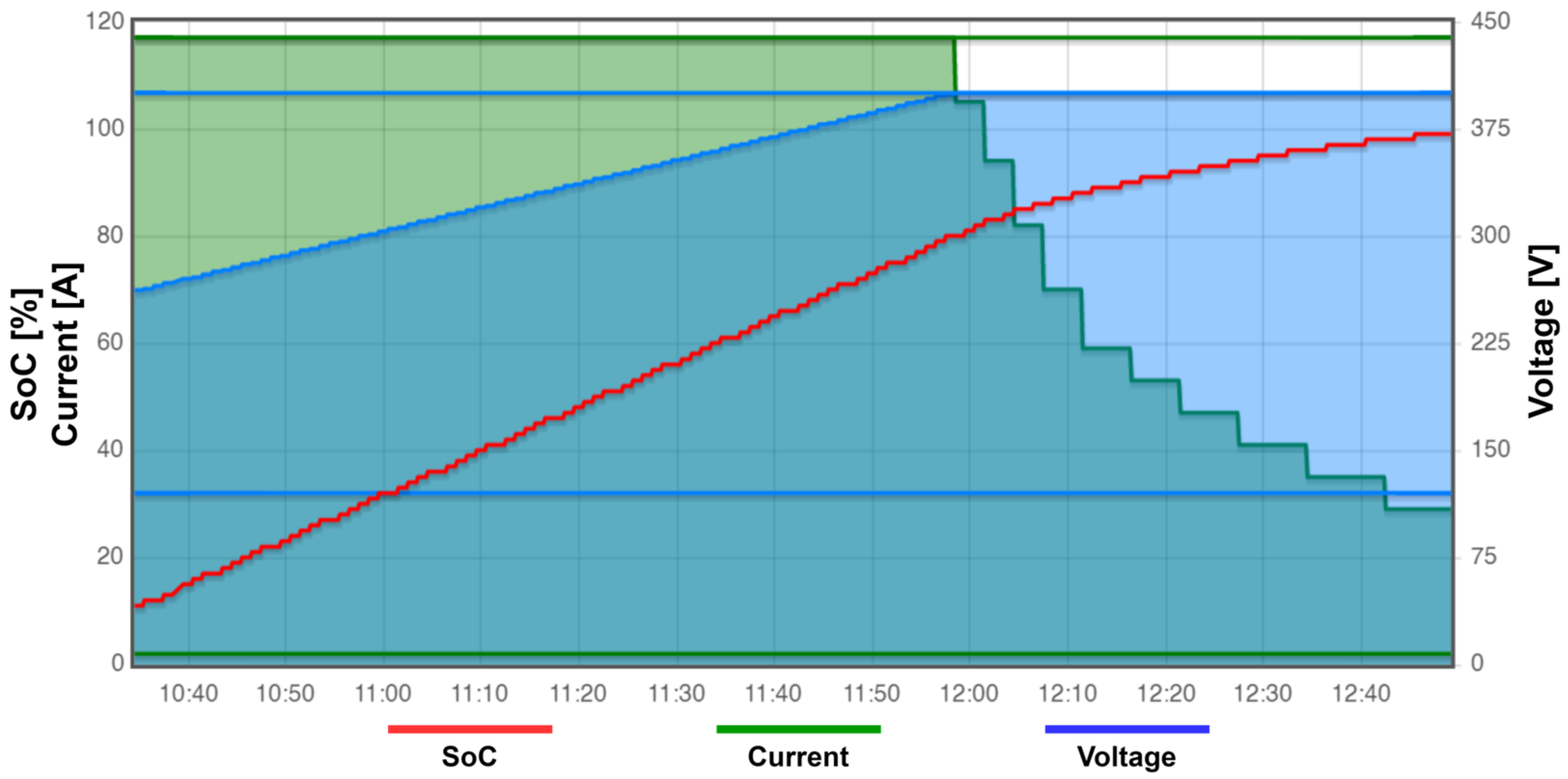
One of the main objectives of the EVpi management code is to control the charging process of the EV battery. This approach allows for the definition of batteries with different characteristics in the EVpi management code. The charging process of an EV Li-ion battery applies both the constant-current (CC) and constant-voltage (CV) charging techniques, known as the CC-CV strategy. The CC-CV strategy consists of dividing the charging process into the two charging techniques [26,27]. Graph A of Figure 5 illustrates the voltage and current behavior during a full charge over time using the CC-CV charging strategy.
Since this work focuses on the communication between the EV and the EVSE, and to emulate the CC-CV strategy, a simplified model of the Li-ion battery was implemented. This model is fundamental to support the exchange of parameters between the controllers and emulate the typical functioning of the charging process of an EV, generating the corresponding curves, and bringing the developed system closer to a real charging process. Nonetheless, some influencing behaviors, such as temperature and cell balance, were set aside. To implement this model, the EVpi management code was adapted regarding the following approaches: (1) It was defined that the change from the CC to the CV charging technique would be performed when the EV battery was at 80% of its SoC. At that instant, the voltage reaches its maximum charging voltage, and the current begins to drop from its maximum value. Basically, the CC charging technique is used while the EV battery SoC remains in range [0, 79], and the CV charging technique is used from 80% upwards; (2) it is assumed that the voltage curve in the CC charging technique is linear, i.e., it can be approximated by a straight line; and (3) it was defined that the electrical current curve in the CV charging technique was also approximated, but in this case, another approach was used. The range [80, 100] is divided into 10 sub-ranges, where each sub-range represents 2% of the battery SoC. In these sub-ranges, the maximum current is multiplied by the corresponding coefficient, reducing the electrical current value, similar to a sequence of decreasing steps, whilst the battery SoC increases. When implementing these approximations, the current and voltage behavior during the charging process of the EV’s virtual battery for the system follows the representation plotted in graph B of Figure 5. The characteristics of the Li-ion battery considered in Figure 5 and used in this work are represented in Table 3.
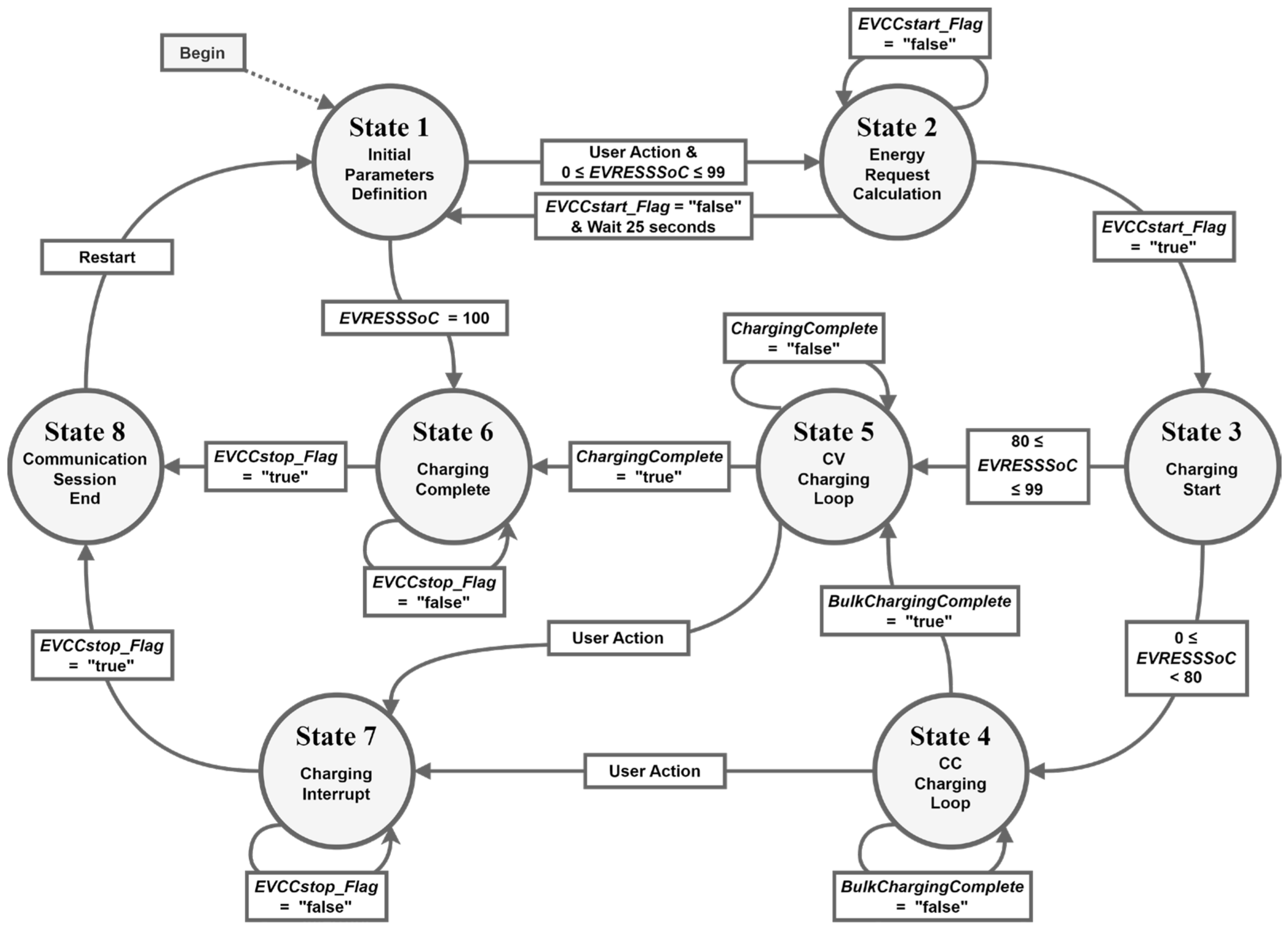
The EVpi management code implements a finite state machine consisting of eight states, as shown in the diagram represented in Figure 6. These states are described in the following passage.
The EVpi State 1, named Initial Parameters Definition, translates the condition where the user of the vehicle starts defining, through the EV HMI, the limits of the current and voltage supported by the vehicle. The user can also define the initial state of charge of the EV for the subsequent charging emulation. The EVpi management code, in this state, is only responsible for accepting these values. To obtain a more realistic charge emulation, these values should be introduced according to the values of the virtual battery implemented in the management code. After having the initial parameters defined, the user allows the EVpi management code to change its state through interaction with the EV’s HMI. If the vehicle battery is fully charged, the EVpi management code changes its state to number 6. Else if the vehicle battery needs to be charged, the EVpi management code changes to State 2.
At EVpi State 2, named Energy Request Calculation, the EVpi management code computes the amount of energy required to reach an SoC of 100%. It then gives the order to the EVCC to start the communication session. Through the EVCC start flag, the management code checks whether the EVCC has been able to establish the communication session with the SECC. In the case of success, the EVpi management code changes its state to State 3. After 25 s, if the EVpi management code is not able to establish a communication with the EVSEpi, the algorithm returns to State 1.
In EVpi State 3, named Charging Start, the charging parameters are exchanged before the charging of an EV takes place. In other words, the EVpi management code sends the EV parameters to its own communication controller and receives the EVSE parameters from it. The parameters sent via the EVCC are as follows: (1) the EVCC identifier, (2) the values of the maximum current and voltage supported for the EV, and (3) the EV SoC. The parameters received at the EVCC are as follows: (1) the communication session identifier, (2) the EVSE identifier, (3) the values of the maximum current, voltage, and power supported for the EVSE, and (4) the minimum values of the current and voltage supported for the EVSE. After this exchange of information, the current, voltage, and power limits are defined for the charging process, respecting the limits of the EV and the supply equipment. Once these limits are established, the charging emulation process is initiated by sending the “Start” value through the charge progress parameter. Also, if the SoC of the vehicle is below 80%, the state changes from State 3 to State 4 or to State 5 if the SoC is already above or equal to 80%. This change in state that depends on the SoC results from the different charging techniques previously described and used in each of the next states.
EVpi States 4 and 5, respectively named CC Charging Loop and CV Charging Loop, translate the CC and CV charging techniques. In these states, the EVpi management code defines the target current and voltage values to charge the EV battery, according to the associated charging technique. These values are sent to the SECC via the EVCC so that the supply equipment can meet the vehicle’s needs. In these states, the values of the EV SoC and the remaining time to reach a full charge level are also computed, according to the current and voltage that the EVSE supports. While the EVpi management code remains in one of these two states, the parameters mentioned above are constantly changing and updating, with a periodicity of 5 s. The transition between these states can be performed in two different ways, either as a result of the EV’s user intervention through the vehicle’s HMI or as a result of the EV’s SoC. When the transition occurs due to the user’s action, both states transition to State 7. This user action results from pressing the stop button on the EV’s HMI. On the other hand, when a threshold value is reached for the EV’s SoC, different situations occur in each of these two states. In State 4, when the vehicle’s SoC reaches 80%, the value of the bulk (or fast)-charge-complete indicator is changed to “true”, and the EVpi management code goes to State 5. This translates the change in the charging technique from CC to CV. In State 5, when the vehicle SoC reaches 100%, the value of the full-charge-complete indicator is changed to “true”, and the EVpi management code goes to State 6.
States 6 and 7 of the EVpi respectively correspond to the Charging Complete and Charging Interrupt conditions, representing the last 5 s of the charging loop and, consequently, the stopping of charging. In State 6, the stopping results from the fully charged status of the EV, while in State 7, the stopping results from the interruption of the charging process via the vehicle’s user. In these states, the EVpi management code is responsible for setting the EV target current and voltage values to zero, as well as the parameter charge progress value to “Stop”. Through the charge progress parameter, the EVCC informs the SECC that a charging stoppage has been requested, thus ending the exchange of the V2G message related to the charging loop and starting the exchange of V2G messages responsible for terminating the communication session. Once the communication session is ended, the EVpi management code sets the EVCC end flag as “true” and transitions to State 8.
In EVpi State 8, named Communication Session End, the main task of the EVpi management code is to reset variables and terminate processes that were started during the previous communication session so that a new communication session can be started. After this update, the management code waits 10 s and transitions to State 1 (i.e., its initial state), when a new charge emulation can be started.
The main objective of the EVSEpi management code is to control the EVSE’s charging process. To do so, it requires access to the voltage and current limits. Under real circumstances, these values are restricted due to the power limits of the electrical grid, or when there is no connection to the electrical grid, due to the power limits of the battery system. In a smart charging scenario, local generation from renewable energy sources should be used to modulate these values. In the charge emulator system, these limits are predefined by the CPO through the HMI of the EVSE. The EVSEpi management code is also responsible for calculating the energy transferred during each charging period and the associated cost, according to energy tariffs. It is also responsible for sending this information to an IoT platform.
The IoT platform used in this system is Emoncms [28]. Besides storing data, it also allows for generating dashboards and graphs of the charging parameters over time. These temporal graphs are extremely important for the CPO, as they can monitor all the information that was and is being processed during the charging processes.
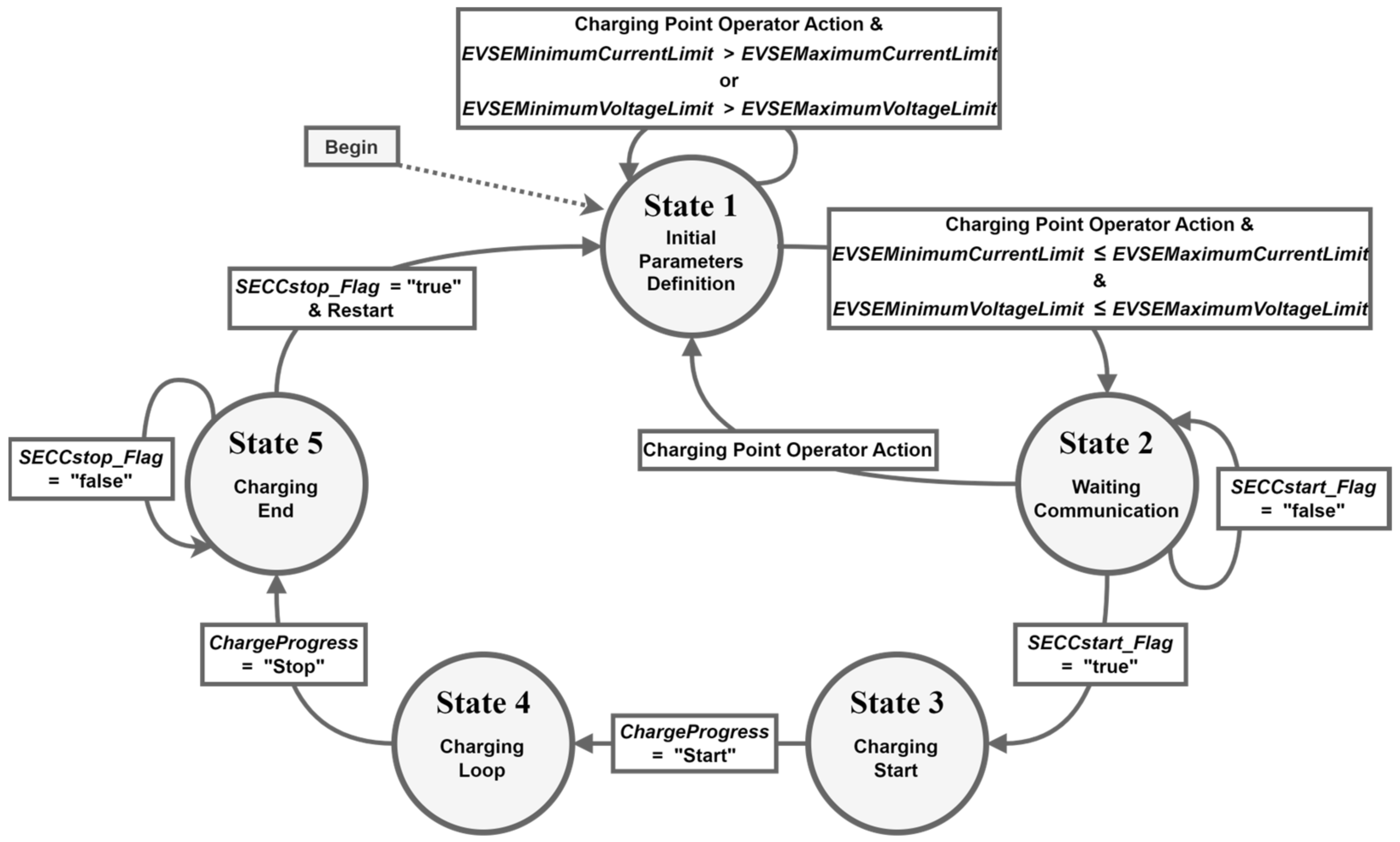
The EVSEpi management code implements a finite state machine consisting of five states and is shown in the diagram in Figure 7. These states are presented in the following passages.
EVSEpi State 1, named Initial Parameters Definition, is where the CPO starts by defining, through the supply equipment’s HMI, the maximum and minimum current and voltage values supported for the EVSE. After validating the entered parameters, the EVSEpi management code transitions to State 2.
In EVSEpi State 2, called Waiting Communication, the EVSEpi management code activates the SECC so that it waits for a connection from the EVCC. If a new communication session is detected, the SECC signals the EVSEpi management code through the “true” value of SECC start flag, which causes a transition to State 3. The EVSEpi management code can be kept in State 2 for an undefined time while waiting for communication establishment. However, the CPO can interrupt it through a stop button at the HMI of the EVSE, causing the management code to return to its initial state (State 1).
EVSEpi State 3, named Charging Start, functions similarly to the EVpi’s State 3. The charging parameters are exchanged between the SECC and the SECC before the beginning of the power transfer. The parameters sent via the SECC are as follows: (1) the communication session identifier; (2) the EVSE identifier; (3) the maximum current, voltage, and power limits supported for the EVSE; and (4) the minimum current and voltage limits supported for the EVSE. The parameters received via the SECC are as follows: (1) the EVCC identifier; (2) the current and voltage limits supported for the EV; and (3) its SoC. This allows for the definition of the current, voltage, and power limits of the charging process, as well as its length and associated cost. This information is sent via the EVSEpi management code to the IoT platform. After completing this set of tasks, the EVSEpi management code checks the state of the progress parameter value. If its value is “start”, then the charge emulation begins, as does the exchange of V2G messages related to the charging loop. This leads to the transition to State 4.
In EVSEpi State 4, called Charging Loop, the EVSEpi management code receives from the EVCC the values of the remaining time to reach a full charge, the target current and voltage to use in the charging process, and the EV’s SoC. The management code then defines the values of the EVSE’s electrical current and voltage, according to the power available from the electrical grid, renewable energy sources, and/or local batteries. In this state, the EVSEpi management code also sets up parameter values that are not part of the ISO 15118 communication protocol, such as the EVSE present power, the charge energy, and the charge energy cost. These parameters are updated at every charging loop. In State 4, the EVSEpi management code is also responsible for sending the charge information to the IoT platform. This information is sent with a periodicity of 1 min (i.e., every 12 charging loops). The EVSEpi management code transitions to State 5 only when the charging process ends, that is, when the charge progress parameter becomes equal to “Stop”.
In EVSEpi State 5, named Charging End, the EVSEpi management code ensures that the EVSE’s values of current, voltage, and power are zero. Thereafter, the connection between the communication controllers is finished, and the final information about the charge is sent for the last time to the IoT platform. Finally, the EVSEpi management code checks the value of the SECC’s end flag to ascertain whether the communication session has ended. Once the communication session finishes, it resets the local variables, waits for 10 s, and returns to its initial state (State 1).
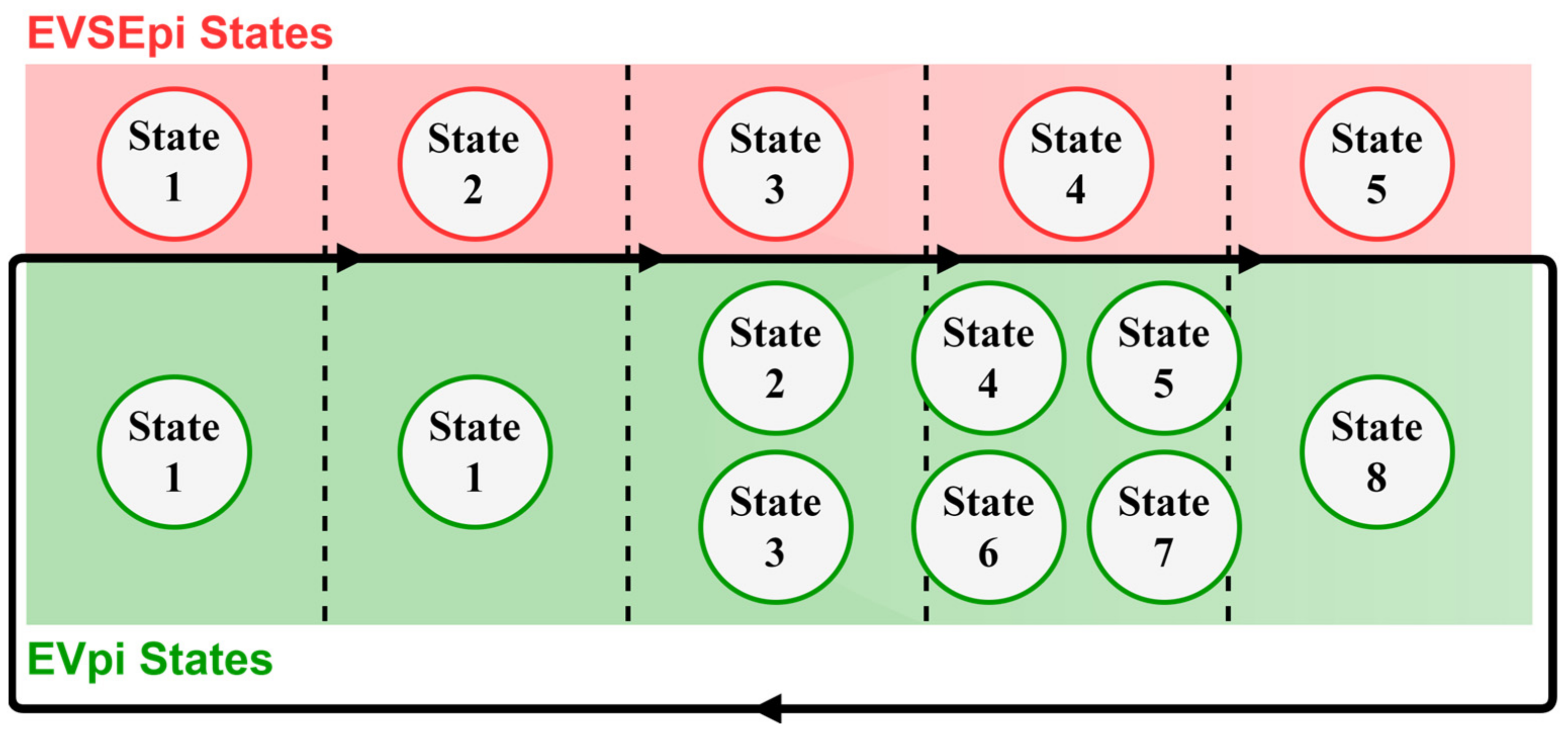
Figure 8 illustrates how the states of each module (EVpi and EVSEpi) are combined to make the implemented system work. During the system’s operation, each EVSEpi state is associated with one or more states at the EVpi. However, at any given instant, only a one-by-one association might exist. For example, State 4 of the EVSEpi is related to States 4, 5, 6, and 7 of the EVpi, but no more than one of these four states can exist at the same time. So, if the EV is charging using the CC charging-loop technique, both the EVpi and the EVSEpi should be in State 4.
It should be noted that, for the system to operate correctly, the EVSEpi management code must be in State 2 before the EVpi management code transitions from State 1 to State 2, as shown in the diagram in Figure 8.

3.2.4. Human–Machine Interfaces

The HMIs of the EV and EVSE allow for defining the limits of the voltage and current supported for each device before the communication session starts. This way, the system allows different charging scenarios to be emulated. These interfaces also provide information about the EV’s charging status that is updated every 5 s. The HMIs were developed in the JAVA programming language with the aid of the Swing graphical user interface tool of the Netbeans IDE, and they are controlled using the associated management codes. In the following passages, we describe each one of these interfaces in the EVpi and EVSEpi.
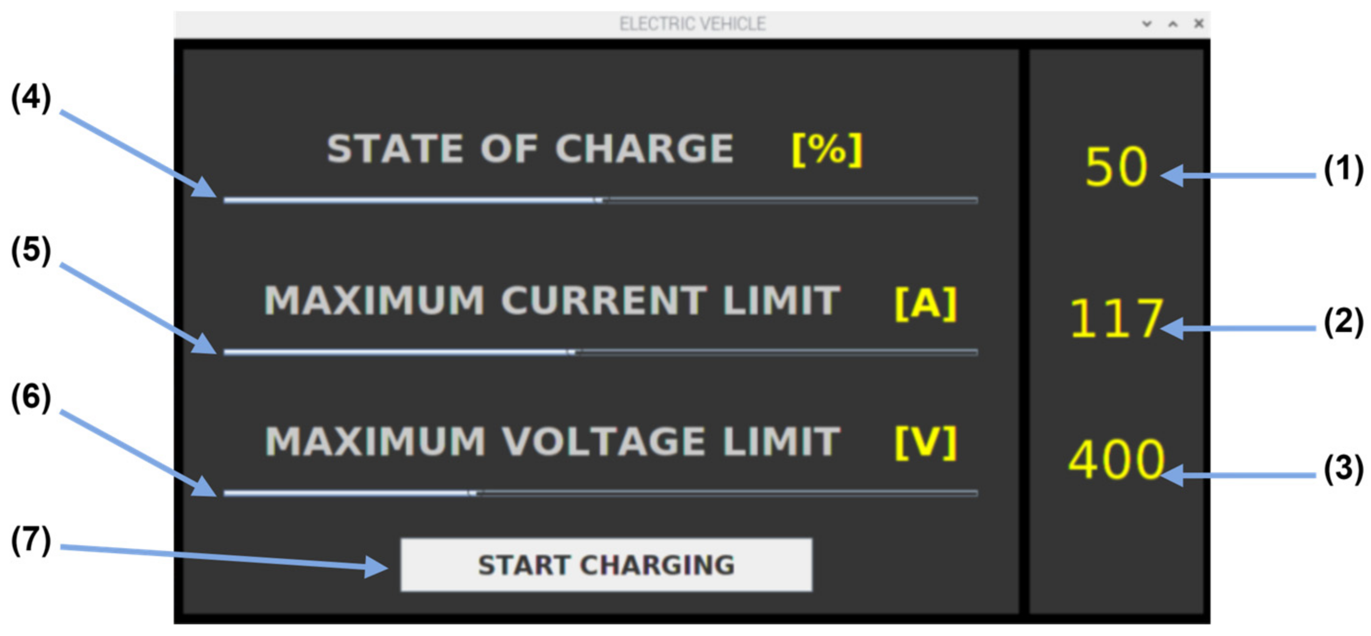
The HMI of the electric vehicle (EV HMI) allows the initial configuration (as shown in Figure 9), which corresponds to the behavior of State 1 of the EVpi management code.
When button (7) in Figure 9 is pressed, the EV’s HMI presents a new interface with the EV’s charging screen (shown in Figure 10). This interface allows for the monitoring of all the parameters of the EVpi management code states (except for the first state). In it, the user can observe the information associated with the status of both the charging process and the communication session.
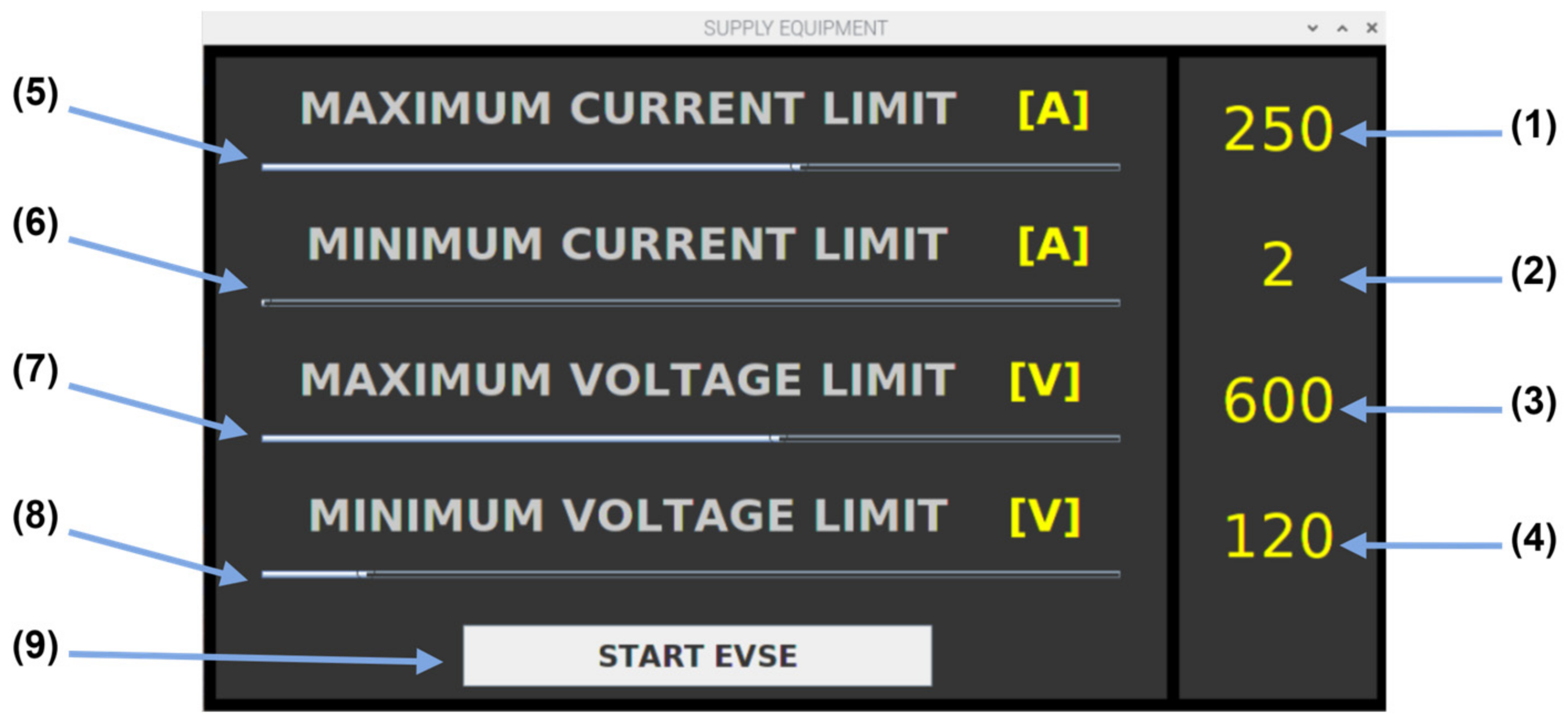
The HMI at the supply equipment (EVSE HMI) has a structure that is similar with that of the EV’s HMI but adapted to the charging station’s requirements. In its initial screen, this interface displays the EVSE’s initial parameterization screen, as shown in Figure 11.
After the definition of the maximum and minimum limits of both the current and tension, the EVSE’s HMI displays the charging screen shown in Figure 12. The charging screen allows for the monitoring of all states of the EVSEpi management code except the first one. It also allows for monitoring information about the charging process, as well as the communication session. Different from the charging screen of the EV’s HMI, the EVSE’s HMI screen is made available before the communication session starts.

3.3. Task-Scheduling Algorithm

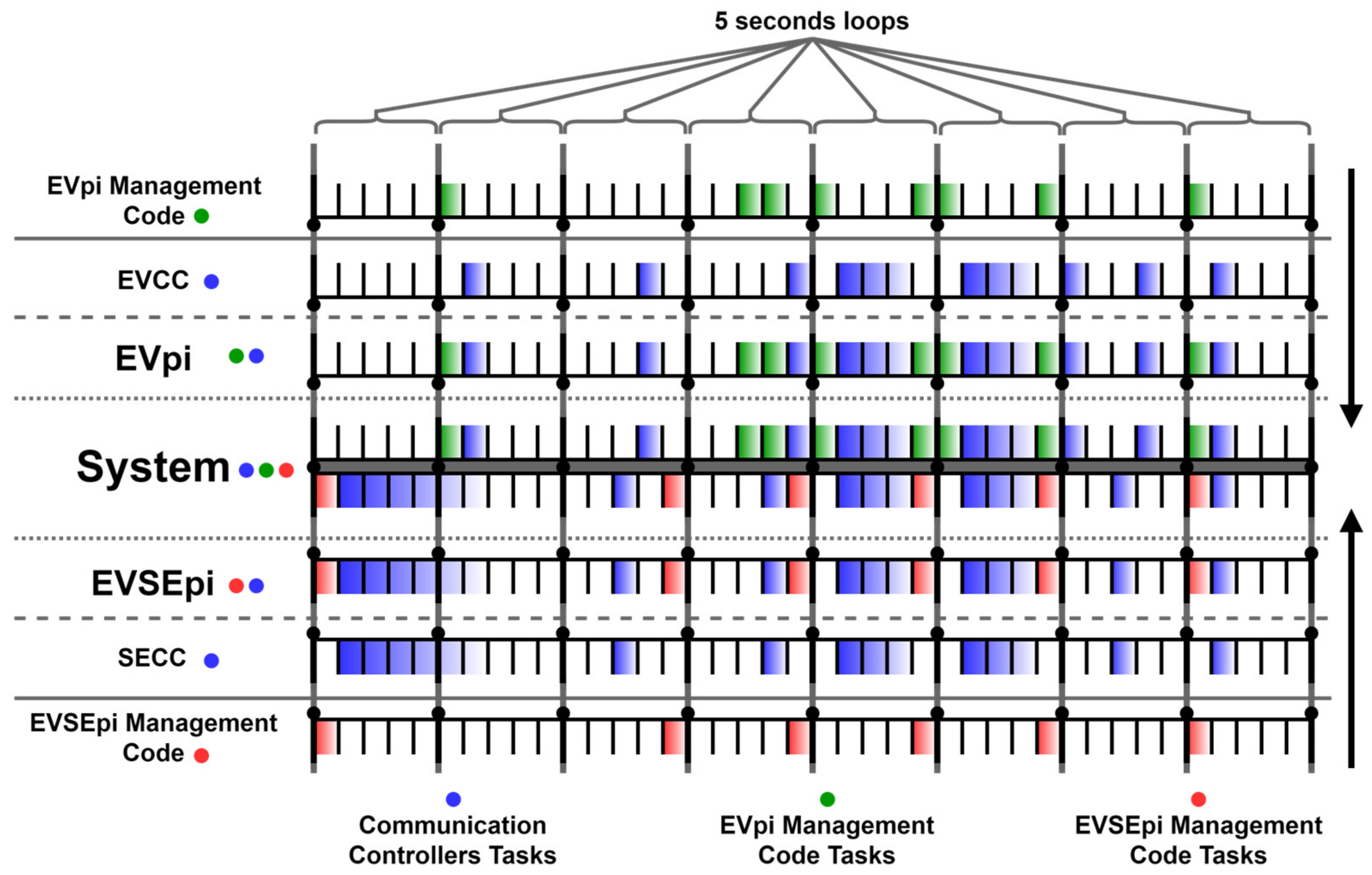
The charging emulation system implements a task-scheduling algorithm to ensure a synchronized information flow, preventing failures or collisions. This algorithm enhances the system’s performance by reducing the processing load and avoiding collisions when accessing the parameter file in each module. The set of tasks performed in the system is decomposed by the tasks performed via the EVpi and EVSEpi. The set of tasks performed via the EVpi result from the tasks performed via the EVpi management code and the EVCC. In turn, the set of tasks performed via the EVSEpi results from the tasks performed via the EVSEpi management code and the SECC. Figure 13 presents the task scheduling at both ends.
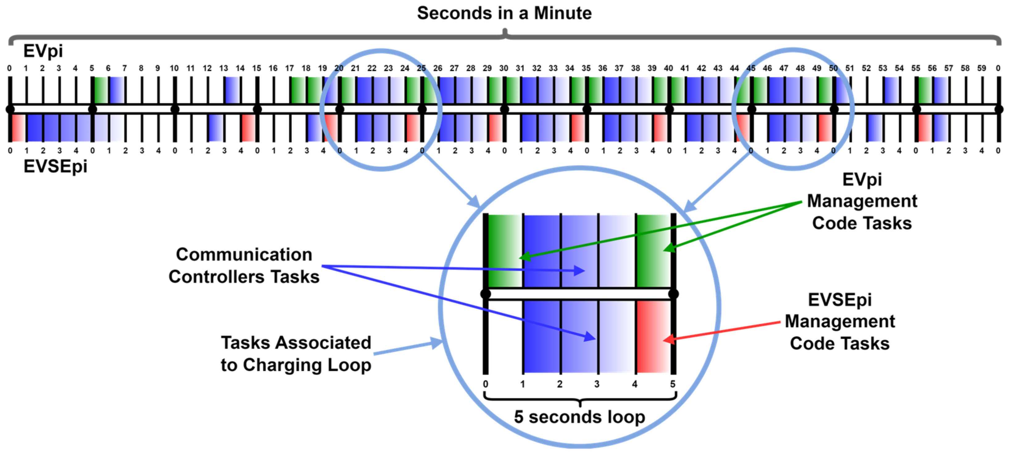
The scheduling algorithm operates in 5-s loops in which each second corresponds to a set of tasks that do not compromise the information flow, as can be seen in Figure 14. This cyclic approach maintains the integrity and efficiency of the emulation system.
The tasks are separated by 1-s intervals and have a running time of less than 1 s. However, a second is reserved for each set of tasks, reducing the system load. The scheduling of each of these tasks is repeated with a periodicity of 5 s. For instance, if a given task runs in the time interval between 0 and 1 s, the algorithm repeats this task in multiples of 5 s; i.e., the task can be started at seconds 0, 5, 10, 15, 20, 25, and so on, as exemplified in Figure 15.
The EVCC adopts the same temporization pattern as the SECC, making it possible to synchronize the processes during the communication session. The adoption of the 5-s loops resulted from the analysis of the number of tasks that the modules can perform without compromising the system’s operability. Since each module is implemented in a Raspberry Pi 3—Model B microcomputer, and the controllers communicate through wireless networks, 3 s were reserved for the communication part. The remaining 2 s of the 5-s of the loop were reserved for the tasks of the management code at each module, including analyzing and updating charging parameters and updating their respective HMI.
One of the scenarios that led to the development of the charge-emulating system was its evaluation in contexts where renewable energy sources are integrated in, or close to, the charging infrastructure. The implementation of charge-responsive systems requires a continuous information exchange between both ends. To this end, in the following passages, we present how the charge parameters are exchanged between the EVPi and the EVSEPi.

3.4. Parameter Exchange during the Charging Process

The scheme represented in Figure 16 illustrates how the system parameters are exchanged during a charging emulation session. The CurrentDemand V2G message is used in the DC charging loop to illustrate the exchange of information between the EV (EVPi) and the EVSE (EVSEPi).
The numbering (1) to (12) in Figure 16 represents the key steps in the parameter exchange process:
  • The EVpi management code generates the updated values of vehicle parameters and sends them to the register list of the parameters file;
  • The EVCC, when preparing to send the request message (CurrentDemandReq), sends the updated values to the register list of the vehicle parameters file;
  • The EVCC sends the CurrentDemandReq to the SECC, containing in its body the vehicle’s parameters;
  • The SECC, upon receiving the CurrentDemandReq, sends the vehicle parameters to the register list of the supply equipment parameters file;
  • The EVSEpi management code obtains the values of the parameters from the vehicle via the parameters file of the supply equipment. These parameters are used with the EVSE for the processing of the charging level, tariff calculation, and data monitoring via the CPO. It also allows applies scheduling algorithms (not used in this system);
  • The EVSEpi management code, after receiving the vehicle’s parameters and processing them, makes this information available to its HMI;
  • According to the available power, the EVSEpi management code generates the updated values of the parameters at the supply’s equipment and sends them to the register list of its parameter file;
  • After receiving the request message (CurrentDemandReq) from the EVCC, the SECC creates the response message (CurrentDemandRes). It uses the updated values of the EVSE parameters through the list of registers in its parameter file;
  • The SECC sends the response message (CurrentDemandRes) to the EVCC, containing in its body the EVSE parameters;
  • The EVCC, upon receiving the CurrentDemandRes, sends the EVSE parameters to the register list of the parameters file on the EV side;
  • The EVpi management code obtains the values of the EVSE parameters via the EV parameter file. These parameters are used via the vehicle for charge processing;
  • The EVpi management code, after receiving the parameters from the EVSE and processing them, makes the resulting information available to its HMI.
Figure 16 highlights the continuous loop of communication and adjustment between the EV and EVSE during a charging session.

4. Resulting System and Demand Response Evaluation

This section starts by describing the implemented ISO 15118 EVSE and EV emulator system. It then evaluates the system’s capability of supporting demand response when integrated with a photovoltaic renewable energy source.

4.1. Results of an Emulated Charging Process

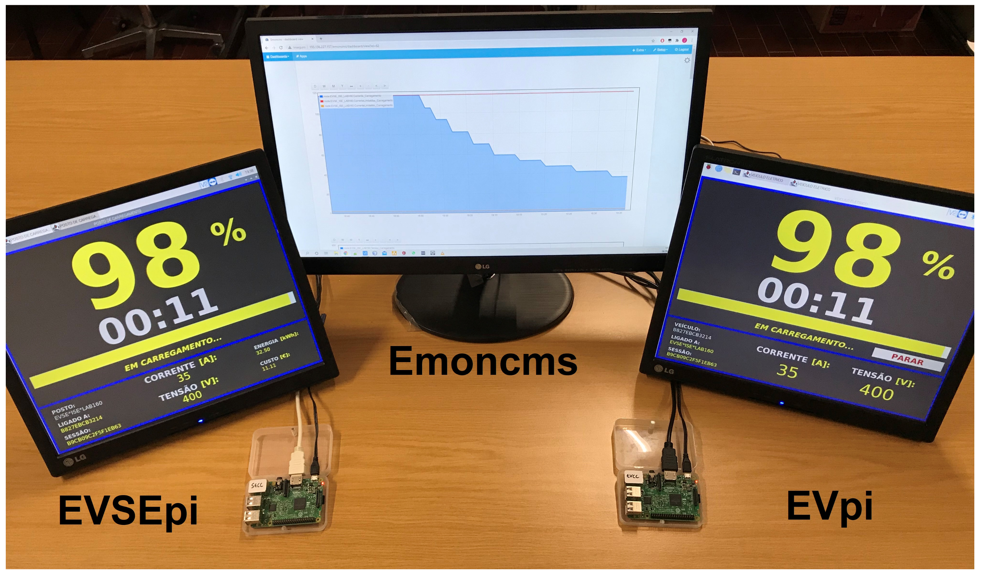
Figure 17 shows the final product of the charging emulation system resulting from the architecture presented in the previous section.
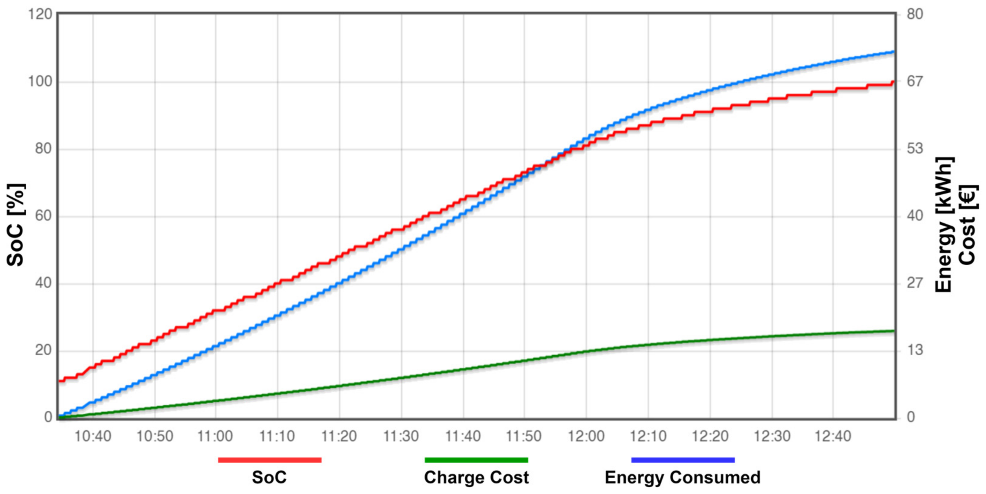
The information shown in the charts of the IoT platform reflects the performed charge emulation. In each charge emulation, graphs are created in the IoT platform, with data from both the EV and EVSE. These data are sent to the IoT platform with a periodicity of 1 min via the EVSE. This allows for the monitoring of the parameters exchanged via the ISO 15118 communication protocol during the charging emulation process. Two of these graphs are presented in Figure 18 and Figure 19, translating into an emulated charge with the initial conditions presented in Table 4.
Figure 18 and Figure 19 illustrate the temporal evolution of the key parameters during a charging emulation session. The graph shown in Figure 18 illustrates the values of the current, voltage, and SoC variables during the charging emulation process. The graph in Figure 19 illustrates the values of the energy consumed and its associated cost during the charging emulation process. These graphs are generated based on the data sent to the IoT server (Emoncms) every minute. The graphs display the changing values of the current, voltage, state of charge, energy consumed, and cost over time, reflecting the dynamic nature of the charging process and the interaction between the EV and EVSE.
With the information in these graphs, it is possible to verify that the EV starts the charging emulation with a SoC of 10%, around 10:34 h and ends it, with a SoC of 100%, around 12:49 h. During these 2 h and 15 min, the EV charges 90% of its battery, with an energy transfer of approximately 72.7 kWh. This emulation was performed in a time period in which electricity had its highest cost (peak hours), so the 72.7 kWh was transferred from the electricity grid to the EV battery, resulting in a charging cost of 17.30 EUR, according to the tariff applied at the EVSE.

4.2. Evaluation of the Responsiveness of the System for Demand Response Purposes

Since the energy generated from some renewable energy sources can be highly intermittent, the system should be able to adapt swiftly to power variations. In the following, we evaluate its responsiveness to varying generation levels.
To evaluate the system’s capability of supporting demand response, it was integrated with a photovoltaic RES. The system’s performance was analyzed based on its ability to align the charging process with the availability of renewable energy, thereby minimizing reliance on the grid and optimizing the use of green energy. The responsiveness of the system in a demand response scenario was evaluated, focusing on the periodicity between SECC and EVCC transmissions. During the development of the system, a periodicity of 5 s was selected. However, it is important to assess whether this value is adequate in terms of: (1) the difference between charging power and generation power and (2) the number of packets per second it requires.
To perform this assessment, an energy generation dataset from a high-definition sampling of a photovoltaic unit was considered [29]. The dataset includes power output per square meter collected via a unit of photovoltaic panels over nearly 11 h of daylight on a cloudy day with high intermittency levels.
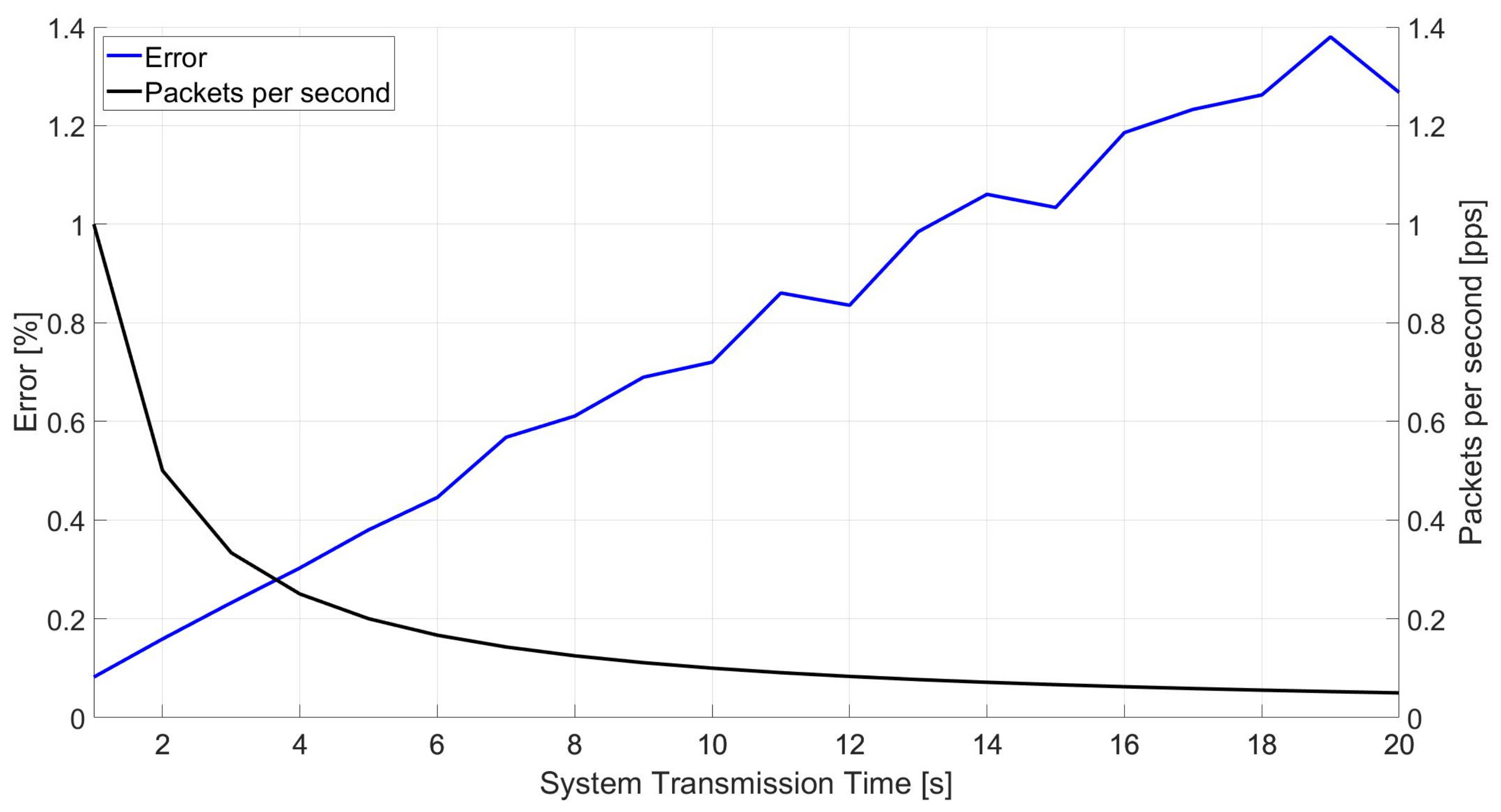
In order to evaluate the mismatch between generation levels and charging levels, the system’s responsiveness was simulated with different communication intervals between the SECC and the EVCC. It was considered that the photovoltaic generation levels were transmitted to the SECC every 100 milliseconds. The transmission periodicity between controllers was then altered from 1 to 20 s. For each of these values, the percentual error between the generation power and the charging power was measured, as well as the number of packets per second required in each scenario. Figure 20 shows the associated results, highlighting that, as the communication interval increases, the percentual error between the generation and charging powers also increases, closely linearly. On the contrary, the number of packets per second decreases exponentially.
From the graph of Figure 20, it is evident that a 5-s communication interval used in the task management algorithm can be seen as a compromise, providing a relatively low percentual error between generation and charging levels (0.3798%) and maintaining a manageable number of packets per second (0.2 packets per second). This periodicity ensures that the system remains responsive to changes in the generation levels, thereby supporting an efficient demand response mechanism.
Considering a periodicity of communications between SECC and EVCC of 5 s, Figure 21 plots the difference between generation and charging levels. The values transmitted via the photovoltaic panel unit and the values transmitted between the communication controllers are very close throughout the daily sample. In light of these results, the utilization of the 5 s periodicity between transmissions in the setup for the task-scheduling algorithm is justified.

5. Discussion, Conclusions, and Future Developments

The developed system successfully emulated a charging system using the ISO 15118 communication protocol between two microcomputers, providing a platform to observe the dynamic behavior of exchanged parameters throughout the communication session, mimicking real-world charging interactions. The implementation involved the development of management codes for both endpoints, i.e., the EV and EVSE. Within the EV module, a virtual Li-ion battery was implemented to emulate changes in charging parameters, employing CC and CV charging techniques to realistically approximate actual charging behavior. In the EVSE module, charging tariffs were implemented alongside a connection to an IoT platform, enabling the storage and future analysis of all emulation data. This enables researchers to observe how the system adjusts to real-time changes in energy availability, which is crucial for integrating RES into EV charging infrastructure. The emulation system also allows for the testing of different charging scenarios, providing a platform for optimizing algorithms and improving the overall efficiency of the charging process. Additionally, HMIs were developed, facilitating the interaction between an EV user and a CPO while providing real-time visualization of dynamic charging parameters.
A key finding of this work is the system’s ability to adjust the charging parameters through the V2G communication interface in response to limitations on the electrical grid, a crucial feature for implementing charging stations that integrate RES. In scenarios where RES are utilized, the EVSE can dynamically communicate the available power limit to the EV, based on the generated power. The implemented system serves as an important tool for the testing and validating of the ISO 15118 protocol in a controlled environment. Ensuring a real-time data exchange between the EV and EVSE is crucial.
The use of Wi-Fi for communication, while convenient, may not fully replicate the power-line communication used in some EV charging systems. Future developments should consider implementing power-line communication over the control pilot line. Also, although the battery model implemented in this work effectively emulates real charging behavior, incorporating more complex models, such as the one used in [30], could enhance the system’s realism even further.
Transitioning from the current emulation system to a real-world implementation poses several challenges and considerations. While the emulation system effectively mimics the behavior of an EV charging system using the ISO 15118 communication protocol, real-world deployment requires addressing factors such as scalability, interoperability with existing infrastructure, and user acceptance. Ensuring seamless integration with the diverse range of EV models and charging stations currently in use will be critical. Additionally, the infrastructure must support various communication protocols and adapt to the unique requirements of different regions and regulatory environments.
Future developments will focus on addressing the transition from controlled emulation to real-world implementation. Key areas for further research and development include the following: (1) scalability: extending the system to a more comprehensive framework that allows for testing V2G communication dynamics in larger and more complex scenarios, which includes scaling up the number of EVs and EVSEs to evaluate system performance under higher loads and more varied conditions; (2) physical system integration: integrating the EVpi and EVSEpi modules into a physical system that includes RES and batteries, building upon the digital twin introduced in previous research [30], which will involve testing the system’s interoperability with actual hardware and ensuring that it meets real-world performance standards; and (3) renewable energy communities: applying the system within the context of renewable energy communities and extending it to also consider electric boats, as explored in previous research on Culatra Island [31,32], which involves assessing the system’s effectiveness in supporting sustainable energy practices and community-based energy management.
While the developed emulation system provides a robust platform for testing and optimizing EV charging processes using the ISO 15118 protocol, several challenges remain before a real-world implementation can be achieved. Addressing scalability, interoperability, user acceptance, and regulatory constraints will be crucial for successful deployment. Additionally, overcoming technical hurdles and ensuring accurate real-time data management will enhance the system’s reliability and effectiveness. Future research should focus on bridging the gap between controlled emulation and practical application, ensuring the system’s readiness for real-world use and its contribution to sustainable energy solutions.

Author Contributions

Validation, P.J.S.C.; Investigation, J.B.S.; Writing—original draft, A.M.B.F., C.C. and A.P.; Project administration, J.M. All authors have read and agreed to the published version of the manuscript.

Funding

This work was supported by the Portuguese Foundation for Science and Technology (FCT) through the following individual research grants: 2021.08721.BD and 2021.08754.BD. The work was also supported by Project AGERAR+, Almacenamiento y Gestión de Energía Renovable para el fomento de la participación de pequeños y medianos prosumidores en redes eléctricas inteligentes (Project ID 0091_AGERAR_PLUS_6_E), funded by the European Union under the FEDER (Fundo Europeu de Desenvolvimento Regional) and INTERREG programs.

Data Availability Statement

The original contributions presented in the study are included in the article, further inquiries can be directed to the corresponding authors.

Conflicts of Interest

The authors declare no conflict of interest.

List of Abbreviations

ACAlternate current
CCConstant current
CPOCharge point operator
CVConstant voltage
DCDirect current
EVElectric vehicle
EVCCElectric vehicle communication controller
EVSEElectric vehicle supply equipment
HMIHuman–machine interface
IoTInternet of Things
RESRenewable energy sources
SECCSupply equipment communication controller
SoCState of charge
V2GVehicle-to-grid

References

  1. Szumska, E.M. Electric Vehicle Charging Infrastructure along Highways in the EU. Energies 2023, 16, 895. [Google Scholar] [CrossRef]
  2. International Energy Agency. Global EV Outlook 2019. Available online: https://www.iea.org/reports/global-ev-outlook-2019 (accessed on 25 April 2024).
  3. International Energy Agency. Global EV Outlook 2024. Available online: https://www.iea.org/reports/global-ev-outlook-2024 (accessed on 25 April 2024).
  4. Lopes, J.A.P.; Soares, F.J.; Almeida, P.M.R. Integration of Electric Vehicles in the Electric Power System. Proc. IEEE 2011, 99, 168–183. [Google Scholar] [CrossRef]
  5. de Hoog, J.; Thomas, D.A.; Muenzel, V.; Jayasuriya, D.C.; Alpcan, T.; Brazil, M.; Mareels, I. Electric vehicle charging and grid constraints: Comparing distributed and centralized approaches. In Proceedings of the 2013 IEEE Power & Energy Society General Meeting, Vancouver, BC, Canada, 21–25 July 2013. [Google Scholar] [CrossRef]
  6. Momoh, K.; Zulkifli, S.A.; Korba, P.; Sevilla, F.R.S.; Afandi, A.N.; Velazquez-Ibañez, A. State-of-the-Art Grid Stability Improvement Techniques for Electric Vehicle Fast-Charging Stations for Future Outlooks. Energies 2023, 16, 3956. [Google Scholar] [CrossRef]
  7. International Electrotechnical Commission (IEC). IEC 61851-1: Electric vehicle conductive charging system—Part 1: General requirements. 2017. Available online: https://webstore.iec.ch/publication/33644 (accessed on 9 February 2024).
  8. ISO 15118; Road Vehicles—Vehicle to Grid Communication Interface (Parts 1–20). International Organization for Standardization (ISO): Geneva, Switzerland, 2022.
  9. SwitchEV. RISE-V2G. Available online: https://github.com/SwitchEV/RISE-V2G (accessed on 14 April 2024).
  10. Alotaibi, I.; Abido, M.A.; Khalid, M.; Savkin, A.V. A Comprehensive Review of Recent Advances in Smart Grids: A Sustainable Future with Renewable Energy Resources. Energies 2020, 13, 6269. [Google Scholar] [CrossRef]
  11. Sadeghian, O.; Oshnoei, A.; Mohammadi-ivatloo, B.; Vahidinasab, V.; Anvari-Moghaddam, A. A comprehensive review on electric vehicles smart charging: Solutions, strategies, technologies, and challenges. J. Energy Storage 2022, 54, 105241. [Google Scholar] [CrossRef]
  12. Ohanu, C.P.; Rufai, S.A.; Oluchi, U.C. A comprehensive review of recent developments in smart grid through renewable energy resources integration. Heliyon 2024, 10, e25705. [Google Scholar] [CrossRef] [PubMed]
  13. Mültin, M. ISO 15118 as the Enabler of Vehicle-to-Grid Application. In Proceedings of the 2018 International Conference of Electrical and Electronic Technologies for Automotive, Milan, Italy, 9–11 July 2018. [Google Scholar] [CrossRef]
  14. Madhusudhanan, S.; Sivraj, P. Development of Communication Simulator for Electric Vehicle Charging following ISO 15118. In Proceedings of the 2022 IEEE North Karnataka Subsection Flagship International Conference, Vijaypur, India, 20–21 November 2022. [Google Scholar] [CrossRef]
  15. Sayed, N.E. A Prototypical Implementation of an ISO-15118-Based Wireless Vehicle to Grid Communication for Authentication over Decoupled Technologies. In Proceedings of the 2019 AEIT International Conference of Electrical and Electronic Technologies for Automotive, Turin, Italy, 2–4 July 2019. [Google Scholar] [CrossRef]
  16. Oulcaid, M.; El Fadil, H.; Njili, S.; Zytoune, O.; Bajit, A. Experimental Implementation of a Wireless Communication System for Electric Vehicle WPT Charger. In Proceedings of the 10th International Conference on Innovation, Modern Applied Science & Environmental Studies, Istanbul, Turkey, 12–14 May 2022. [Google Scholar] [CrossRef]
  17. Wellisch, D.; Lenz, J.; Faschingbauer, A.; Pöschl, R.; Kunze, S. Vehicle-to-Grid AC Charging Station: An Approach for Smart Charging Development. IFAC-PapersOnLine 2015, 48, 55–60. [Google Scholar] [CrossRef]
  18. OCPP 2.0.1; Open Charge Point Protocol (OCPP). Open Charge Alliance (OCA): Arnhem, The Netherlands, 2020.
  19. Oumaima, B.; Hassan, E.F.; El Jeilani, S.; Halima, H.; Abdelaziz, K. Integration of Communication Between EV and EVSE Based on ISO 15118 with an OBD-II System. In Lecture Notes in Electrical Engineering; Springer: Berlin/Heidelberg, Germany, 2024. [Google Scholar] [CrossRef]
  20. Stahleder, D. Hardware-in-the-Loop Co-Simulation Environment for Testing Grid Integration of Electric Mobility with Precise Charging Models. Master’s Thesis, Technische Universität Wien, Vienna, Austria, 2018. [Google Scholar] [CrossRef]
  21. Pallander, R. Implementation of HomePlug Green Phy standard (ISO15118) into Electric Vehicle Supply Equipment (Dissertation). Luleå University of Technology 2021. Available online: https://urn.kb.se/resolve?urn=urn:nbn:se:ltu:diva-83881 (accessed on 9 February 2024).
  22. Jakó, Z.; Knapp, Á.; El Sayed, N. Wireless Authentication Solution and TTCN-3 based Test Framework for ISO-15118 Wireless V2G Communication. Infocommunications J. 2019, 11, 39–47. [Google Scholar] [CrossRef]
  23. International Organization for Standardization (ISO). ISO 15118-1:2019. Available online: https://www.iso.org/standard/69113.html (accessed on 25 April 2024).
  24. Ju, S.-H.; Lee, I.-H.; Song, S.-H.; Seo, H.-S. Communication Interoperability between EV Charging Infrastructure and Grid. Int. J. Eng. Technol. 2018, 7, 215–221. [Google Scholar]
  25. International Organization for Standardization (ISO). ISO 15118-2:2014. Available online: https://www.iso.org/standard/55366.html (accessed on 25 April 2024).
  26. Thomson, S.J.; Thomas, P.A.R.; Rajan, E. Design and Prototype Modelling of a CC/CV Electric Vehicle Battery Charging Circuit. In Proceedings of the 2018 International Conference on Circuits and Systems in Digital Enterprise Technology, Kottayam, India, 21–22 December 2018. [Google Scholar] [CrossRef]
  27. Shen, W.; Vo, T.T.; Kapoor, A. Charging algorithms of lithium-ion batteries: An overview. In Proceedings of the 2012 7th IEEE Conference on Industrial Electronics and Applications, Singapore, 18–20 July 2012. [Google Scholar] [CrossRef]
  28. Emoncms.org. Emoncms. Available online: https://emoncms.org/ (accessed on 14 April 2024).
  29. Government of Canada. High-Resolution Solar Radiation Datasets. Available online: https://natural-resources.canada.ca/energy/renewable-electricity/solar-photovoltaic/18409 (accessed on 14 April 2024).
  30. Francisco, A.M.B.; Monteiro, J.; Cardoso, P.J.S. A Digital Twin of Charging Stations for Fleets of Electric Vehicles. IEEE Access 2023, 11, 125664–125683. [Google Scholar] [CrossRef]
  31. Santos, J.; Pacheco, A.; Monteiro, J. Implementation Process of a Local Energy Community in Portugal—The Case of Culatra Island. In INCREaSE 2023—Advances in Sustainability Science and Technology; Springer: Cham, Switzerland, 2023. [Google Scholar] [CrossRef]
  32. Pacheco, A.; Monteiro, J.; Santos, J.; Sequeira, C.; Nunes, J. Energy transition process and community engagement on geographic islands: The case of Culatra Island (Ria Formosa, Portugal). Renew. Energy 2022, 184, 700–711. [Google Scholar] [CrossRef]
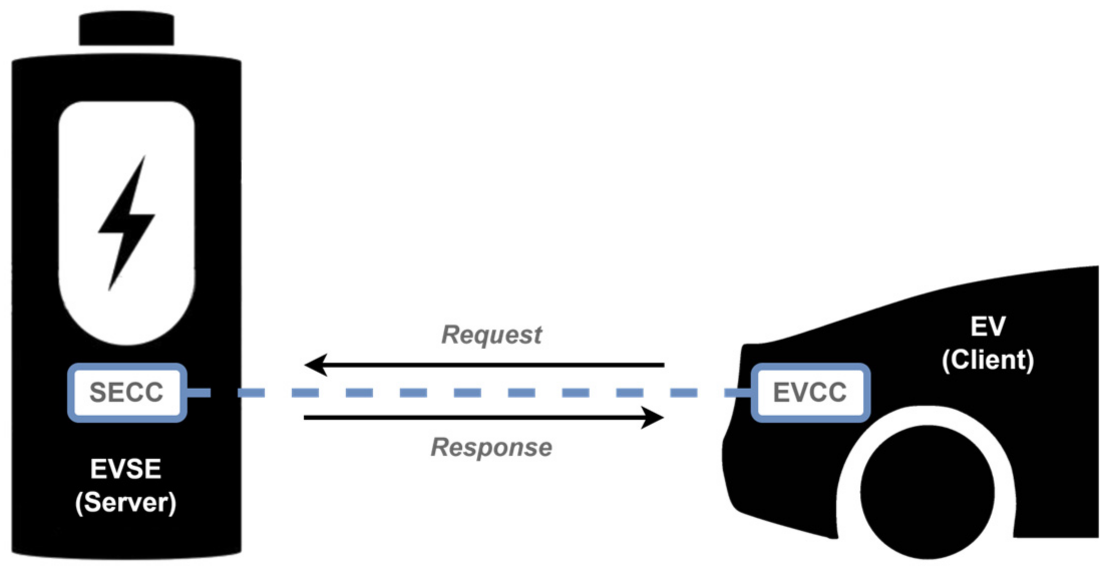
Figure 1. ISO 15118 client–server communication model between the SECC and the EVCC. For each type of V2G message, the client, on the EVCC side, sends a request message to which the server, on the SECC side, answers with a response message.
Energies 17 03045 g001
Figure 2. Flowchart of the types of V2G messages. In this flowchart, it is possible to see how the different types of V2G messages are used, depending on the power transfer modes (AC or DC), payment options (certificates and EIM), value-added services, metering receipt request, and charging progress (“Start”, “Stop”, or “Renegotiate”). The continuous black lines represent the V2G message flow implemented in the system that was developed in this work during a charging communication session.
Energies 17 03045 g002
Figure 3. General structure of the implemented charging emulation system, comprising the vehicle endpoint, the supply equipment, and the required interfaces for the user of the EV and for the charging point operator, together with the communication infrastructure at both ends.
Energies 17 03045 g003
Figure 4. Architecture of the implemented system, comprising two modules. On the left side, the EVSEpi module is composed of the SECC, the EVSE parameter file, the EVSEpi management code, and the EVSE HMI. On the right side, the EVpi module is composed of the EVCC, the EV parameter file, the EVpi management code, and the EV HMI. Together, these eight sub-modules allow the implementation of the proposed charging emulation system according to the ISO 15118 standard, as well as the interaction with the charge point operator and the user and interfacing with the Internet-of-Things (IoT) platform.
Energies 17 03045 g004
Figure 5. Graphs of the CC-CV charging strategies. (A) The left side represents the conventional behavior of the electrical current and voltage curves during the charging of a Li-ion battery using the constant-current (CC) and constant-voltage (CV) techniques. (B) The right side represents the approach made in this work to approximate the behavior of the virtual battery, implemented in the EVPi management code, to the behavior of a conventional Li-ion battery.
Energies 17 03045 g005
Figure 6. Finite state machine diagram of the EVpi management code, consisting of eight states.
Energies 17 03045 g006
Figure 7. Finite state machine diagram of the EVSEpi management code, consisting of five states.
Energies 17 03045 g007
Figure 8. Articulation of states between the EVpi and EVSEpi. In order for the system to work, each state in the EVpi needs to have a corresponding state at the EVSEpi.
Energies 17 03045 g008
Figure 9. Initial configuration screen for the EV. In this interface, the values of the EV SoC (1) and the maximum limits of the current (2) and voltage (3) supported for the EV can be defined. These parameters are defined individually, respectively, through sliders (4), (5), and (6). The range of values of each slider can be changed in the source code. Once the initial parameters have been defined, button (7) initiates the transmission of the information to the EVpi management code, allowing the start of the communication session that will lead to the emulated charging of the EV.
Energies 17 03045 g009
Figure 10. Charging screen of the EV. When the charging process has not yet started, only some information is made available at the charging screen (A), such as the numerical value of the EV’s SoC (1), the level of the SoC (2), the information bar (3), and the EVCC identifier (4). When the charging process starts, the charging screen displays the remaining information (B), including the time left to reach the full charge (5) presented in an hour:minute format (hh:mm), the EV target current (7), the EV target voltage (8), the EVSE identifier (9), and the communication session identifier (10). While charging, the user can still request the charge to stop using the stop button (6) that is available in this interface.
Energies 17 03045 g010
Figure 11. Initial parameterization screen of the EVSE. This screen allows for the definition of the maximum current (1), the minimum current (2), the maximum voltage (3), and the minimum voltage (4) supported for the EVSE. These parameters are individually adjustable, respectively, through sliders (5), (6), (7), and (8). Once the initial parameters have been defined, button (9) is responsible for initiating the transmission of the associated information to the EVSEpi management code.
Energies 17 03045 g011
Figure 12. EVSE’s charging screen. When the charging process has not yet started, only some information is made available at the EVSE charging screen (A), such as the information bar (1) and the EVSE identifier (2). It also includes a stop button (3) that can be used by the CPO only during this stage, allowing the EVSE HMI to get back to the initial parameterization screen, canceling the wait for the establishment of a new communication session. Once the charging process starts (B), the remaining information on the charging screen is made available, such as the EV’s SoC (4), the time left to a full charge (5) displayed in an hour:minute format (hh:mm), the SoC level (6), the charged energy (7), the associated cost (8), the EVSE’s charging current (9) and voltage (10), the EVCC identifier (11), and the communication session identifier (12).
Energies 17 03045 g012
Figure 13. Task scheduling of the charge emulation system. In this figure, the tasks performed via the EVpi management code are represented in green, and the tasks performed via the EVSEpi are represented in red. The tasks performed via the communication controllers (EVCC and SECC), although implemented on separate machines, are represented with the same color (blue) because these tasks are performed together during the communication session. No task is overlapped between the SECC and EVSEpi management code or between the EVCC and the EVCC management code.
Energies 17 03045 g013
Figure 14. Loops of the task-scheduling algorithm. The 60 s of a minute are divided into 12 loops of 5 s. Each 5-s loop corresponds to a charging loop of the respective management code. Each interval of 1 s in a 5-s loop allows for the execution of a set of tasks associated with that charging loop.
Energies 17 03045 g014
Figure 15. Task-scheduling algorithm. When a given task is executed, the algorithm repeats that same task with a periodicity of 5 s; e.g., if it is executed for the first time in the interval between 3 to 4, it will be repeated at 3 s, 8 s, 13 s, 18 s, 23 s, 28 s, etc.
Energies 17 03045 g015
Figure 16. Parameter exchange in a charging emulation session between the EVSE (EVSEPi) and the EV (EVPi). In this figure, the flow of the CurrentDemand V2G message is depicted, showcasing the interaction between the EV and the EVSE during a DC charging session.
Energies 17 03045 g016
Figure 17. Implemented system. On the left side, the EVSE’s HMI is shown, and close to it is the EVSEpi’s microcomputer, responsible for the execution of the associated management code and the SECC source code. On the right side is the EV’s HMI. A little further down is the microcontroller (EVpi) responsible for the execution of its management code and the EVCC source code. In the center of the figure, a chart from the IoT platform (Emoncms) is presented to illustrate the information logged during an emulated charging process.
Energies 17 03045 g017
Figure 18. Chart of the electrical current, voltage, and SoC variables during an emulated charging process. The red line represents the SoC as a percentage, the green line represents the charging current in amperes, and the blue line represents the voltage of charging in volts. The top and bottom straight green lines represent the maximum and minimum currents that the charging process can reach. The top and bottom straight blue lines represent the maximum and minimum voltage that the charging process can reach.
Energies 17 03045 g018
Figure 19. Graph of the energy and cost values during an emulated charging process. The red line represents the SoC in a percentage, the green line represents the charge cost in EUR, and the blue line represents the energy consumed during the charging in kilowatts hour.
Energies 17 03045 g019
Figure 20. Power mismatch between charging and generation power. The blue line represents the percentual error between the generation power and the charging power, as the transmission periodicity is changed between 1 s and 20 s. The black line represents the rate of packets per second in the same conditions.
Energies 17 03045 g020
Figure 21. Power levels from the photovoltaic unit versus charging levels. The black line represents the photovoltaic unit transmission values, and the red lines represents the communication system transmission values. The excerpt, representing around 15 min, illustrates that the difference between the charging and generation levels is low.
Energies 17 03045 g021
Table 1. Comparative review of key references considering the primary topics of this work.
Ref.ISO
15118
Demand
Response
RES
Integration
EmulationSimulation
[14]
[15]
[16]
[17]
[19]
[20]
[21]
[22]
This work
Table 2. ISO 15118 different V2G message types and their associated actions.
V2G Message TypesAssociated Action
SessionSetup
[AC & DC]
Establish the V2G communication session
ServiceDiscovery
[AC & DC]
EVSE makes available all its services to an EV (e.g., charging services and payment options)
ServiceDetail
[AC & DC]
An EV gets more information about an additional EVSE service
PaymentServiceSelection
[AC & DC]
An EV chooses which services to use, as provided via EVSE previously
PaymentDetails
[AC & DC]
Exchange details when certificates are chosen as a payment option (e.g., e-mobility account identifier)
Authorization
[AC & DC]
EVSE allows, or not, the EV to have access to its energy, depending on the validation of the payment option
ChargeParameterDiscovery
[AC & DC]
An EV and EVSE negotiate charging parameters (e.g., current, voltage, and power limits)
PowerDelivery
[AC & DC]
EVSE supplies power to its outlet terminals so the EV can charge its battery
CertificateUpdate
[AC & DC]
An EV requests a new certificate when it is about to expire
CertificateInstallation
[AC & DC]
An EV requests a new certificate when it does not have a valid one; SECC may have to request this certificate from a secondary actor
SessionStop
[AC & DC]
Finish the V2G communication session
MeteringReceipt
[AC & DC]
EVSE digitally signs the charging energy metering information
ChargingStatus
[AC]
Responsible for the charging loop in AC power transfer mode; EV verifies and validates the power consumed via EVSE
CableCheck
[DC]
Checks whether the connector is locked and whether the EV is ready for charge
PreCharge
[DC]
Adjust EVSE voltage to EV battery voltage
CurrentDemand
[DC]
Responsible for charging loop in DC power transfer mode; control parameters are exchanged
WeldingDetection
[DC]
Safety-checks the electrical contacts after the power transfer derived from charging
Table 3. Characteristics of the virtual battery implemented in the EVPi management code.
Total
Capacity
Maximum
Current
Maximum
Voltage
Minimum
Voltage
Nominal
Voltage
235 Ah117 A400 V240 V350 V
Table 4. Charging emulation initial conditions.
EVSE Maximum Current Limit250 AEV State of Charge10%
EVSE Minimum Current Limit2 AEV Maximum Current Limit117 A
EVSE Maximum Voltage Limit600 VEV Maximum Voltage Limit400 V
EVSE Minimum Voltage Limit120 VTariff PeriodPeak
Disclaimer/Publisher’s Note: The statements, opinions and data contained in all publications are solely those of the individual author(s) and contributor(s) and not of MDPI and/or the editor(s). MDPI and/or the editor(s) disclaim responsibility for any injury to people or property resulting from any ideas, methods, instructions or products referred to in the content.