Abstract
This study analyzes the effect of the temperature coefficient of electric resistance on the thermal performance of a film heater for satellite applications. A heating element in the film heater was fabricated using silver paste and screen-printing technology. The temperature distributions of the film heater were numerically simulated on the basis of the heat transfer equation. The temperature coefficient of resistance was evaluated by measuring the film-heater temperature at various voltages using a forward-looking infrared (FLIR) camera. The results showed that the electric resistance linearly increased with a temperature variation. By considering the temperature coefficient of electric resistance, the error of numerical simulation decreased from 22.5% to 10%. The voltage required to reach the maximum allowable temperature at a given sink temperature was higher than the design voltage when the temperature coefficient was not considered. This indicated that greater power would be required to operate the film heater in real satellite applications.
1. Introduction
Technological advancements in the aerospace sector are considered to be a critical determinant of the success and failure of space missions. Satellites serve various purposes, including communication, exploration, and meteorological forecasting. The success of space missions significantly impacts many aspects of our lives over the long term. Spacecrafts, similar to satellites, are subjected to extreme environments—vacuums, cryogenics, and extremely high temperatures—making the selection of materials and temperature control imperative. Temperature regulation must maintain stable operation over extended periods. Attaching metal film heaters to substrates is one of several available thermal management techniques [1]. The advantages of film heaters include their customizability into desired shapes and their thin, flexible nature, which reduces constraints on placement locations. Furthermore, film heaters are electrically controlled, which simplifies operation. Because of these benefits, extensive research has been conducted on film heaters. Moore [2] introduced the etched metal foil heater as an innovative heating method, which has enabled product enhancement and novel ideas.
Film heaters predominantly comprise a metal heating element sandwiched between the insulating films. The European Space Components Coordination (ESCC) provides the standard for the production and performance indicators of film heaters for satellite applications [3]. This standard covers detailed information on film heaters, including materials, specifications, and manufacturing. A very small number of companies produce film heaters for satellites according to this standard. Commercially available products used in satellites include those from Minco Co., Ltd. (Fridley, MN, USA) and Rica Co., Ltd. (Stuttgart, Germany) and use a polyimide film and an alloy predominantly comprising nickel as the heating element [4]. The manufacturing process involves etching, delamination, and cleaning to create a heating-element pattern on the film. This method is analogous to semiconductor fabrication, necessitating elaborate and intricate technology. Alternatively, screen-printing and gravure-printing techniques can be applied to fabricate film-heater elements. Paru Printed Electronics Co., Ltd. (Suncheon, Republic of Korea) manufactures its film heaters by printing silver paste onto polyimide films, followed by a heat-treatment process [5]. The film heater has shown equivalent performance through strict tests. This approach is simpler and more cost- and time-efficient than previous methods. Zhao et al. [6] experimentally demonstrated the thermal and mechanical stability of conductive silver paste. Its high viscosity allows for application across various curvatures and ensures a robust coating because of its flexibility. Moreover, it supports high-temperature outputs at low voltages with rapid thermal response times.
Thermal design for film heaters is conducted by experiments and simulations. The thermal-design method using experiments involves iterative testing with prototypes until optimal performance is achieved. However, the number of iterations can be significantly reduced using simulation-based analyses [4]. Reliable simulations enable the modification of film-heater designs and the prediction of their performance. Rapolu et al. [7] identified and resolved hotspot issues in Kapton RS flexible heaters using predictive simulations. Kim et al. [8] presented performance curves for silver-paste film heaters based on the sink temperature from simulation results. Furthermore, thermal-design research using a film heater attached to a substrate was also conducted. The panel structure of satellites mainly comprises aluminum. Recently, the use of carbon-fiber-reinforced plastic (CFRP), which is lightweight and durable, has increased [9]. Schlitt et al. [10] measured limiting the power density by increasing the power after attaching a film heater from Minco Co., Ltd. to CFRP and aluminum substrates. Choi et al. [11] developed a simulation technique to analyze the heat transfer characteristics of film heaters attached to CFRP or Al 6061 and the power-density requirements for stable heater operation under vacuum conditions.
Metal heating elements generally have a temperature coefficient of resistance. It means that the heating power changes due to a change in electric resistance, depending on the temperature for a given voltage. Ji et al. [12] analyzed the performance of silver nanowire film heaters and adjusted the convective heat transfer coefficient while considering the temperature coefficient of resistance. In addition, research is actively underway to analyze the changes in metal resistance that depend on temperature and to consider these changes in experimental measurements. Park [13] applied the temperature coefficient of resistance to calculate the theoretical temperature of a thin-film heater patterned using platinum. Scorzoni et al. [14] calculated the theoretical resistance of a thin-film heater on a glass substrate by applying the temperature coefficient of resistance. Jakubowska et al. [15] provided the temperature coefficient of resistance for a new thick-film material based on nanoscale silver paste. The temperature coefficient of resistance is crucial for the performance, input values, and design of film heaters, significantly influencing these aspects. Nevertheless, there is a lack of research analyzing the thermal performance of silver-paste film heaters by incorporating the temperature coefficient of resistance into thermal analysis simulations.
Consequently, this study analyzed the effect of the temperature coefficient of electric resistance on the thermal performance of a film heater for satellite applications. This study aimed to experimentally determine how the resistance of the film heater could change with an increase in temperature. By examining the correlation between temperature and resistance, the temperature coefficient of resistance for silver paste was calculated and applied to thermal analysis simulations to observe fluctuations in simulation errors. Through this simulation technique, the output of the film heater was predicted in a vacuum and various external temperature environments (space environments), and the effect of the temperature coefficient of resistance was analyzed. Furthermore, the effect of the temperature coefficient of resistance on substrate temperature predictions when the film heater was mounted on a substrate was investigated.
2. Materials and Methods
Figure 1 shows the external appearance and dimensions of the film heater for satellite applications used in this study. The film heater measured 152.4 × 25.4 mm, with a thickness of 0.14 mm. Silver paste was printed onto a polyimide film insulator using gravure-printing technology. The silver paste served as the heating element and was densely arranged in curves. The heating element was designed to be 1 mm wide and 1817 mm long, excluding the connectors. This specification is a commonly used size. When printed using screen-printing technology, the designed thickness of the silver paste ranged from 1 to 5 μm. Because of its extremely thin profile, the thickness was measured using scanning electron microscopy (SEM) after sectioning the sample. These measured specifications of the film heater facilitated the development of a three-dimensional (3D) model for the thermal analysis simulation.

Figure 1.
Appearance and dimensions of film heater developed using silver printing.
A thermal analysis was performed using an Ansys 18.2 thermal–electric model under steady-state conditions. Figure 2 shows the boundary conditions of the thermal simulation. When electrical energy was applied to the heating element, it was converted to thermal energy. The generated heat was transferred by conduction through the polyimide film and then exited via convection and radiation heat transfer at the external surface. The vertical thermal resistance of the film heater is shown in Figure 2. Here, denotes thermal conductivity, denotes the emissivity of the material, denotes the Stefan–Boltzmann constant, denotes the surface temperature, denotes the ambient temperature, and denotes the convective heat transfer coefficient, where subscript 1 denotes the polyimide film and subscript 2 denotes CFRP and Al 6061. The atmospheric boundary condition was that convection and radiation heat transfer only occurred outside the film heater. The mesh size of the heating element was 0.3 mm, that of the external film was 0.7 mm, and the total number of elements was 132,982. The space-environment boundary conditions simulated the actual application of the film heater on a satellite. The heater was modeled on a substrate measuring 250 × 250 mm, with a thickness of 2 mm. The mesh size of the substrate was 0.001 m and the total element count was 261,934. In satellite applications, no convection occurs and thermal radiation exists at the surface. The thermal contact resistance due to the adhesive (t,c) was obtained from previous studies [11]. t,c was m2K/W when the film heater was attached to CFRP or m2K/W when the film heater was attached to Al 6061. The material properties of all substances are listed in Table 1. However, the resistivity of the silver paste was inputted using varying values, depending on the temperature and based on experimental results.
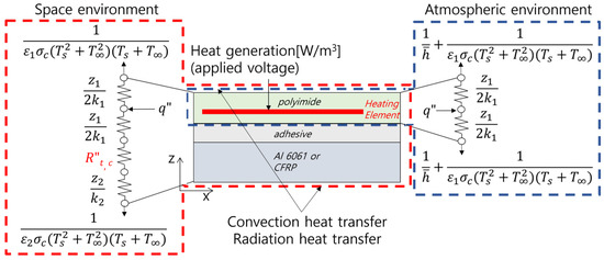
Figure 2.
Boundary conditions of thermal simulations. There are two boundary conditions, atmospheric and space environments.

Table 1.
Material properties.
Figure 3 is a cross-sectional image of a film heater captured via SEM alongside a graph displaying the thickness data of the silver paste in a box-plot format. The sample preparation involved sectioning the cross-section of the heater, followed by stabilization through cold mounting. Subsequent grinding and polishing were performed until the heating element was exposed. Figure 3a shows a cross-sectional image of one of the several film-heater samples, where the darker area represents the polyimide film and the brighter area denotes the silver paste. The measurements were focused on well-sectioned areas, recording heating-element thicknesses of 2.97 and 3.69 μm. Figure 3b shows the thickness data of 26 heating elements in a box plot; the median was 3.33 μm, the first quartile (Q1) was 2.11 μm, and the third quartile (Q3) was 4.54 μm. The average thickness of the silver paste was 3.5 μm, which was within the design thickness range and was used as the thickness of the heating element during 3D modeling.
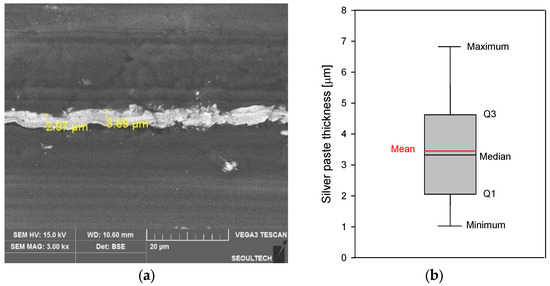
Figure 3.
Cross-sectional image of film heater captured via SEM alongside a graph displaying the thickness data of silver paste in box-plot format: (a) film heater cross-sectional SEM image; (b) box plot of data for 26 heating-element thicknesses.
Figure 4 shows the mesh validation for the 3D model of the film heater. The maximum temperature of the heater at a mesh number of 132,982 changed by less than 1% as the mesh number increased. Therefore, increasing the mesh number over 132,982 did not significantly affect the results.
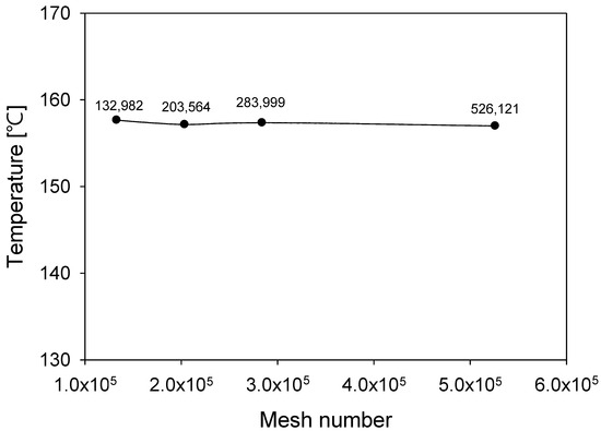
Figure 4.
Maximum temperature change of film heater depending on mesh qulity in steady stae. The applied voltage is 70 V and the ambient temperature is 25 °C.
To accurately determine the temperature coefficient of resistance of a film heater, it is essential to establish the exact relationship between the heater resistance and operating temperature.
Equation (1) represents the relationship between resistance and temperature, where represents the resistance, denotes the reference resistance, represents the temperature, denotes the reference temperature, and represents the temperature coefficient of resistance [16]. The temperature coefficient of resistance quantifies the extent to which the resistance of a specific material changes with temperature, relative to its reference temperature and resistance. This coefficient is expressed in units of . Resistance can be described using Equation (2) as a function of the resistivity of material ( as well as the length (, width (), and thickness (). Variations in resistance and resistivity do not introduce errors into Equation (1), which can also be expressed using Equation (3). Equation (4) rearranges the temperature coefficient of resistance to the left, intuitively representing its meaning.
The thermal analysis modeling of the film heater involved heat generation, heat conduction, convection, and radiation of the resistor and used joule heating and heat transfer equations.
Equation (5) expresses the Joule heating formula, where represents the heat energy generated by the resistor, represents time, represents power, represents voltage, and represents the current. The heat generated per unit time can be expressed as the power converted from electrical energy to thermal energy. In addition, power can be represented as the product of the applied voltage and current, and can be transformed using Ohm’s law. The differential form of Joule heating is given by Equation (6). This represents the power per unit volume, where denotes the volume of the heating element, represents the current density, represents the electric field, represents the DC power per unit volume, and represents the electrical conductivity. and have a reciprocal relationship. Conductive materials satisfy Equations (7) and (8), resulting in the power per unit volume being the product of the square of the current density and resistivity.
The heat generated by a heating element is transferred to the surroundings. Within a film heater, heat conduction is dominant and follows the transient heat conduction equation, as described by Equation (9). Here, denotes the density, denotes specific heat, denotes the Kronecker symbol, and represents each region under consideration. represents polyimide and (= 2) represents silver paste. Because the film heater was vertically mounted for the experiment, the free convection equation for a vertical plate was used.
Equation (10) represents Newton’s law of cooling, where denotes the heat-flux density. The convective heat transfer coefficient was defined as shown in Equation (11), where denotes the Nusselt number, represents the thermal conductivity of the fluid (air), represents the characteristic length, which corresponded with the length of the film heater (152.4 mm). For free convection over a vertical plate, the Nusselt number follows Equation (12) [17]. Here, denotes the Rayleigh number, and the onset of transition in free convection is typically associated with this dimensionless number. The critical Rayleigh number for free convection on a vertical plate is 109. This dimensionless number is the product of the Grashof number (), which represents the ratio of buoyancy to viscosity forces, and the Prandtl number (), which represents the ratio of momentum diffusion to thermal diffusion. Details are provided in Equation (13), where represents the gravitational acceleration, denotes the coefficient of thermal expansion, represents the kinematic viscosity, and denotes the thermal diffusivity. The properties of the fluid change with temperature and the temperature variation within the thermal boundary layer near the heater surface were significant. Therefore, the average temperature between the heater surface and the ambient temperature was used to determine the fluid properties.
Figure 5 shows the variations in the convective heat transfer coefficient with the temperature difference between the heater-surface and ambient temperatures. These coefficients were calculated using Equations (11)–(13). The temperature difference, denoted as , was defined by . Because of free convection, the range of these coefficients did not exceed 25 W/(m2K) [18]. The ambient temperature was calculated at six points, ranging from −100 C to 100 C. The ranges of the temperature differences varied with the ambient temperature. Considering the durability of the film heater, calculations for heater-surface temperatures above 250 C were not performed. The convective heat transfer coefficient nonlinearly increased with the temperature difference. This coefficient rapidly rose at lower temperature differences and was less affected by the external temperature, resulting in closely packed values. As the temperature difference increased, the rate of increase in the convective heat transfer coefficient gradually decreased and the influence of the external temperature became more significant. Consequently, as the external temperature increased, the convective heat transfer coefficient decreased. This phenomenon was due to the variation in the average temperature that determined the fluid properties (viscosity, thermal conductivity, etc.), which was the mean of the heater-surface and external temperatures.
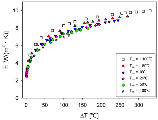
Figure 5.
Variations in the convective heat transfer coefficient and temperature difference ( between heater-surface and ambient temperatures across six ambient temperature settings.
Equation (14) represents the radiation heat transfer, which, similar to convection, occurs outside a film heater. Here, denotes the surrounding temperature. The emissivity of polyimide was 0.74 and 0.85 for CFRP and 0.1 for Al 6061 [19,20,21].
To measure the temperature coefficient of resistance, the resistance and temperature of the film heater were first measured at an arbitrary reference voltage. As the voltage increased, the resistance of the heater was measured and the temperature coefficient of resistance could be calculated using Equation (1). Figure 6 shows a schematic of the experimental setup used to measure the temperature coefficient of resistance of the heater. The experiments were conducted in a room measuring 8 × 8 m and 3 m in height. The initial temperature was 25 C. The experimental space maintained still-air conditions. The film heater was vertically mounted using clamps. A DC power supply was used to energize the film heater, starting at 20 V and increasing in increments of 10 V. The heater temperature was monitored using an FLIR camera (FLUKE-TiS75+, Fluck Corporation, Everett, WA, USA) after allowing the temperature to stabilize for 10 min following each voltage application. The experiment concluded when the maximum heater temperature approached 200 C, with a final voltage of 105.2 V. The resistance at each voltage level was calculated using the voltage and current displayed on the DC power supply, following Ohm’s Law.
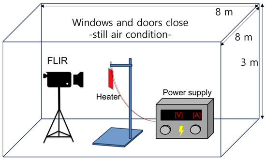
Figure 6.
Schematic of the experimental setup used to measure the temperature coefficient of resistance of a heater.
3. Results and Discussion
Figure 7 and Figure 8 show the thermal images captured using an FLIR camera and the corresponding maximum temperature changes of the film heater and applied voltages, respectively. Figure 7 includes thermal images of the film heater at applied voltages of (a) 20 V, (b) 50 V, (c) 80 V, and (d) 105.2 V. The maximum temperatures of the heater at these voltages were 39.1 , 87.5, 145.5 , and 196.2 , respectively. Conversely, the minimum temperatures remained close to the ambient temperature (25 C), similar to the nonheating sections of the film heater, because of the low thermal conductivity of the polyimide film. The maximum temperatures of the film heater were used as the temperature data to calculate the temperature coefficient of resistance. Figure 8 shows the variation in the maximum temperatures of the film heater and the voltage. A linear curve fit was applied, yielding an value of 0.9973. The curve-fitting results indicated that the maximum temperature of the film heater linearly increased with the voltage.
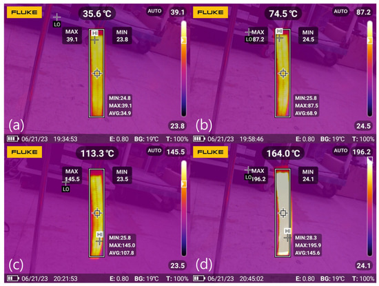
Figure 7.
Thermal images of a film heater captured using an FLIR camera at applied voltages of (a) 20 V, (b) 50 V, (c) 80 V, and (d) 105.2 V.
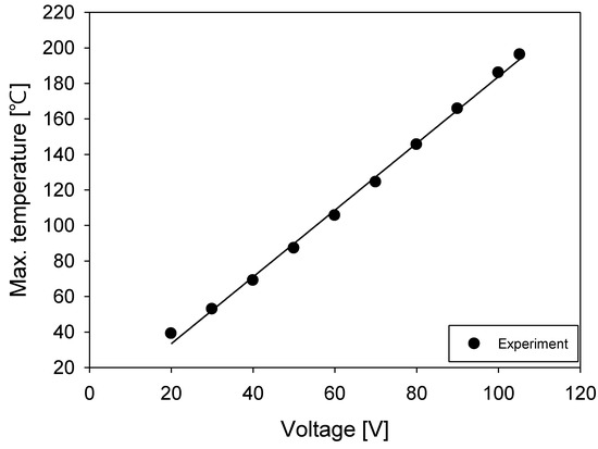
Figure 8.
Change in maximum temperatures of a film heater with voltage.
Figure 9 shows the change in resistivity and the maximum temperature of the film heater. The resistance of the heating element was first calculated and then resistivity was determined using Equation (2). A linear curve fit was applied, with an value of 0.9989. The curve-fitting results indicated that the resistivity of the heating element linearly increased; at a maximum temperature of 39.1 (with 20 V applied), the resistivity was , and at 196.2 (with 105.2 V applied), it was . The resistivity of the heating element increased by 32.98% as the voltage increased from 20 to 105.2 V. The resistivity presented in this figure was used to calculate the material properties of the silver paste in the thermal analysis simulations. To calculate the temperature coefficient of resistance using Equation (3), the reference resistivity and temperature must be established. The point at which the lowest voltage of 20 V was applied was chosen as the reference. The calculated temperature coefficient of resistance for the silver paste was .
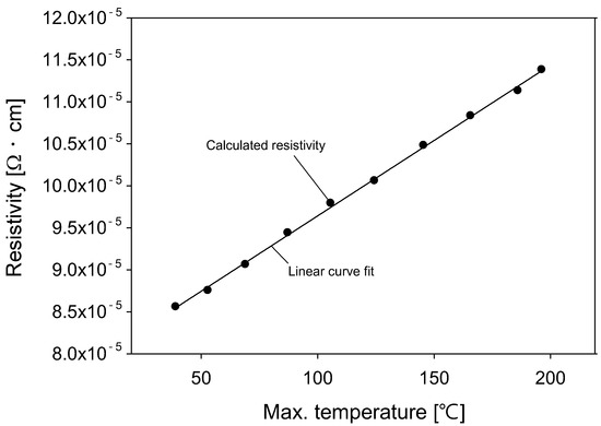
Figure 9.
Change in resistivity with maximum temperature of a film heater.
To investigate the effect of the temperature coefficient of resistance in thermal analysis simulations, two simulations were performed: one with the temperature coefficient applied and the other without. Figure 10 shows the temperature distributions of the film heater for both simulations. The simulations used the atmospheric boundary conditions shown in Figure 2. The ambient temperature was 25 , which was identical to the experimental setup. The voltage was incrementally increased from 20 V in 10 V steps to a final voltage of 105.2 V. The convective heat transfer coefficients were obtained from the data presented in Figure 5 at an external temperature of 25 . Detailed values are presented in Table 2. Figure 10a shows the temperature distribution without the application of the temperature coefficient of resistance and Figure 10b shows it with the temperature coefficient of resistance. The edges of the heater and areas without heating elements maintained lower temperatures, which was consistent with the experimental results. However, the temperature distribution without the temperature coefficient of resistance (Figure 10a) exhibited larger variations with an increase in voltage than that with the temperature coefficient of resistance (Figure 10b). For a quantitative assessment, the maximum temperatures of the film heater were compared.
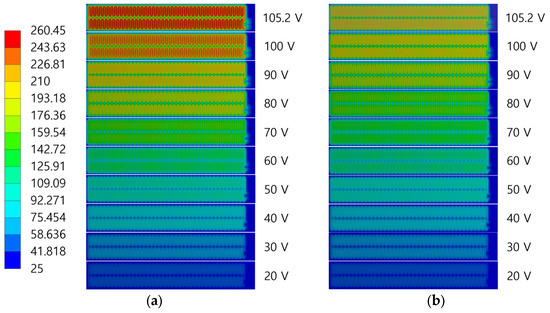
Figure 10.
Temperature contours of a film heater for simulations under atmospheric environment boundary conditions: (a) without temperature coefficient of resistance applied; (b) with temperature coefficient of resistance applied. Unit of temperature is C.

Table 2.
Convective heat transfer coefficients at an external temperature of 25 (Figure 5).
Figure 11 shows the maximum temperatures of the film heater and the applied voltages depicted for the experiment (black), the simulation with the temperature coefficient of resistance applied (blue), and the simulation without the temperature coefficient of resistance applied (red). The experimental data were obtained from Figure 8. Typically, the maximum temperature of the film heater linearly increased with the voltage, even though differences in the slopes were observed. The results with the temperature coefficient of resistance applied showed a smaller slope than those without. Even if the same voltage was applied, the resistance of the heater increased because of the temperature coefficient of resistance and, finally, the output (heater temperature) decreased. Therefore, these results were consistent with the experimental results. When comparing the simulation results with the temperature coefficient of resistance and the experimental data, the temperature differences were 2.54 °C at 20 V and 19.34 °C at 105.2 V. Conversely, when comparing the simulation without the temperature coefficient of resistance with the experiment, the temperature differences were 2.86 °C at 20 V and 62.4 °C at 105.2 V. The application of the temperature coefficient of resistance reduced the simulation error from 22.5% to 10.0%. This demonstrates the necessity of using the temperature coefficient of resistance in the thermal simulations of electrical heaters.
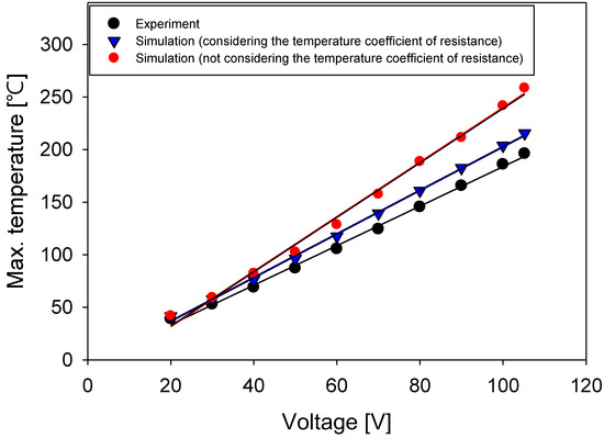
Figure 11.
Maximum temperatures of a film heater with voltage under atmospheric environment boundary conditions.
Simulations can predict the output of film heaters based on the use environment. However, as shown in Figure 11, neglecting the temperature coefficient of resistance can lead to significant simulation errors, potentially resulting in the following scenarios: the film heater could fail because of an overload caused by an incorrect design voltage; critical damage could occur to components; or the internal equipment could fail because of exposure to low temperatures caused by an insufficient output. Therefore, this study analyzed the effect of the temperature coefficient of resistance on predicting the output of film heaters in a space environment. The space environment was assumed to be a vacuum at various sink temperatures of 25 , 0 , −25 , −50 , −75 , and −100 . Figure 12 shows the maximum temperature changes of the film heater and the applied voltage. These changes were the results of simulations under space-environment boundary conditions with the temperature coefficient of resistance applied (blue) and not applied (red). In the space environment, convective heat transfer conditions were omitted and the film heater existed in isolation. The maximum temperature of the film heater linearly increased with the voltage. As the sink temperature decreased, the maximum temperature of the film heater decreased at the same voltage. However, the rate of decrease was not constant and it diminished. In extremely cold regions, the sink temperature had less of an effect on the maximum temperature of the film heater. The rate of increase in the maximum temperature was smaller for the simulation with the temperature coefficient of resistance applied than that without because an increase in resistivity with temperature led to a lower output. At a voltage of 57.5 V, the expected maximum temperature of the heater was, on average, 11.54% higher when the temperature coefficient of resistance was not applied. Not considering the temperature coefficient of resistance could lead to an underestimation of the output of a heater during the thermal-design stage, potentially failing to maintain the proper temperature of electronic devices. The voltages required to reach the control temperature at different sink temperatures was calculated, as shown in Figure 12. The control temperature was set to 150 C, indicated by a red line in the figure. The intersection points on the x-axis (voltage) of the maximum temperature data and the control temperature indicate the voltages required to achieve the control temperature at each sink temperature.
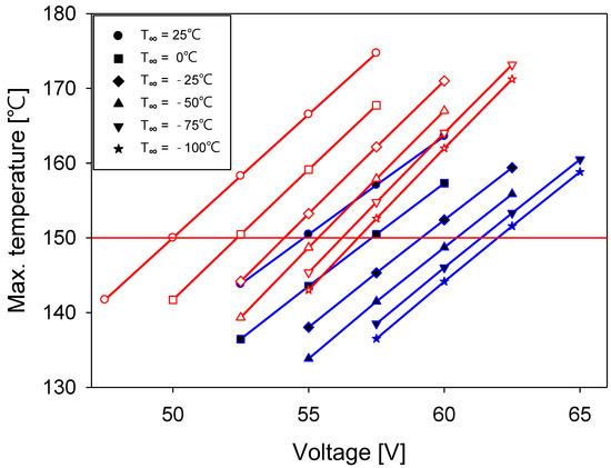
Figure 12.
Maximum temperature changes for a film heater in a space-environment simulation as a function of applied voltage at six sink temperatures. Two simulations were performed: one with the temperature coefficient of resistance applied (blue) and the other without (red).
Figure 13 shows the voltage change of the film heater that was required to reach the control temperature at different sink temperatures. The operational conditions for the film heater included a vacuum and radiation heat transfer typical of a space environment. The voltage required was compared with (blue) and without (red) the temperature coefficient of resistance. A commonality observed was that the voltage required nonlinearly decreased with an increase in sink temperature and sharply dropped to 0 V when the control and sink temperatures equalized. A notable difference was that the voltage required without the application of the temperature coefficient of resistance was, on average, 8.54% lower than that with. When the temperature coefficient of resistance was not considered, the resistance of the heater remained constant. A lower voltage was sufficient to reach the control temperature compared with the case in which the temperature coefficient of resistance was applied. Therefore, if a required voltage without a temperature coefficient of resistance is used when a film heater is mounted on a substrate and in operation, it may result in insufficient heating. In this study, simulations were performed with the film heater attached to a substrate, applying both the required voltages with and without the temperature coefficient of resistance to compare the temperature distributions across the substrates. The substrates used were CFRP and Al 6061, which are commonly used in satellites.
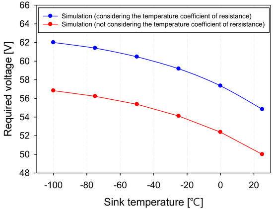
Figure 13.
Required voltage change of a film heater to reach control temperature at different sink temperatures.
Figure 14 shows the temperature contours obtained from a simulation in which the film heater was attached to a CFRP substrate. The boundary conditions were adopted from the space environment shown in Figure 2, with a sink temperature of 0 C. The applied voltage was set according to the required voltage at a sink temperature of 0 C, as shown in Figure 13. Figure 14a shows the temperature contour with an applied voltage of 52.38 V, which did not consider the temperature coefficient of resistance. Figure 14b shows the temperature contour with an applied voltage of 57.35 V, which considered the temperature coefficient of resistance. Because of the low thermal conductivity of CFRP, there was a significant temperature variation; areas near the film heater were significantly hotter, whereas regions farther away closely matched the sink temperature. The maximum temperature of the film heater without the temperature coefficient of resistance was 56.202 C, whereas it was 65.796 C with the temperature coefficient of resistance applied, indicating that the differences in heater output were due to the varying required voltages. The maximum temperatures of a film heater and the substrate may differ; thus, quantitative analyses of the temperature of the substrate are necessary.
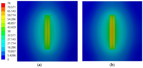
Figure 14.
Temperature contours obtained from space-environment boundary-condition simulation in which a film heater was attached to a CFRP substrate: (a) without temperature coefficient of resistance applied; (b) with temperature coefficient of resistance. Unit of temperature is C.
Figure 15 shows the temperature distribution of CFRP and the distance from the center of the substrate, extracted from the data presented in Figure 14. The temperatures were measured along a line perpendicular to the heater, starting at the center of the heater (distance: 0 mm). Because of the low thermal conductivity of CFRP, the temperature profile followed a Gaussian distribution. Comparisons between the temperature distributions with (blue) and without (red) the application of the temperature coefficient of resistance showed differences in the maximum temperatures of CFRP. With the temperature coefficient of resistance applied, the maximum temperature of CFRP was 42.607 C, whereas the maximum temperature was 36.535 C without it applied. Because of the low thermal conductivity of CFRP, the temperature difference was largest at 0 mm and decreased with an increase in distance from the heater.
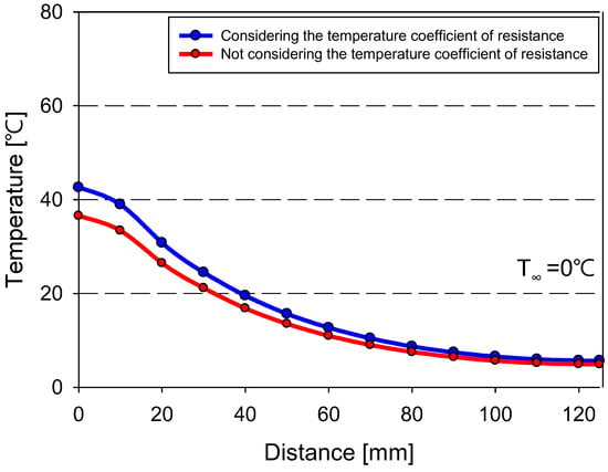
Figure 15.
Temperature distribution of CFRP and distance from the center of the substrate.
Figure 16 shows the temperature contours obtained from a simulation in which the film heater was attached to an Al 6061 substrate. The boundary conditions and sink temperature were the same as those used in Figure 14. Figure 16a shows the temperature contour with an applied voltage of 52.38 V, which did not consider the temperature coefficient of resistance. Figure 16b shows the temperature contour with an applied voltage of 57.35 V, which considered the temperature coefficient of resistance. Because of the higher thermal conductivity of Al 6061 than CFRP, the temperature variation was less pronounced. The temperatures across the film heater and substrate were more uniform, with the maximum and minimum temperature differences not exceeding 8 C. The maximum temperature of the film heater without the temperature coefficient of resistance was 67.07 C, whereas it was 75.954 C with the coefficient applied, indicating that the differences in heater output were due to the varied applied voltages. Similar to CFRP, the maximum temperatures of a film heater and an Al 6061 substrate may differ. Therefore, the substrate temperature was separately analyzed.
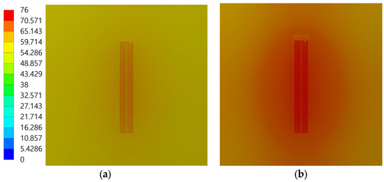
Figure 16.
Temperature contours from a space-environment boundary-condition simulation in which a film heater was attached to an Al 6061 substrate: (a) without temperature coefficient of resistance applied; (b) with temperature coefficient of resistance. Unit of temperature is C.
Figure 17 shows the temperature distribution of Al 6061 and the distance from the center of the substrate, extracted from the data presented in Figure 16. The location for temperature extraction was the same as that in Figure 15. Because of the high thermal conductivity of Al 6061, the temperature variation was minimal. When the temperature coefficient of resistance was used (blue), the maximum temperature of Al 6061 was 71.553 C compared with 63.328 C obtained when the coefficient was not used (red). Unlike CFRP, the temperature difference between the conditions with and without the temperature coefficient of resistance applied remained constant regardless of the distance from the center. The higher the thermal conductivity of the substrate, the greater the effect of the temperature coefficient of resistance on the substrate temperature predictions. At a sink temperature of 0 C, the difference between the control temperature of the film heater and the maximum temperature of the substrate was 107.4 C for CFRP and 78.5 C for Al 6061. However, if the temperature coefficient of resistance was not considered, this temperature difference became even larger, significantly complicating the prediction of substrate temperatures.
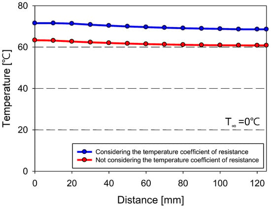
Figure 17.
Temperature distribution of Al 6061 and distance from the center of the substrate.
4. Conclusions
In this study, the effect of the temperature coefficient of electric resistance on the thermal performance of film heaters was investigated. A film heater was subjected to gradually increased voltages whilst being monitored using an FLIR camera. To calculate the temperature coefficient of resistance, the resistance changes of the heating element were analyzed at various applied voltages and heater temperatures. The effect of the temperature coefficient of resistance on the thermal performance predictions for heater and satellite applications (attached to CFRP and Al 6061 substrates) was analyzed using numerical simulations.
The results confirmed that the heater resistance linearly increased with temperature, allowing the calculation of an effective temperature coefficient of resistance (). Applying this coefficient in thermal simulations reduced the simulation error from 22.5% to 10%. At the same voltage, the heater temperature was higher when the temperature coefficient of resistance was not applied. The voltage required to reach the control temperature (150 °C) without the temperature coefficient of resistance applied was, on average, 8.54% lower than that with it applied.
Simulations with the film heater attached to CFRP and Al 6061 substrates at the required voltages revealed significant differences. The CFRP substrate, which had a lower thermal conductivity, showed smaller substrate temperature differences between the cases with and without the temperature coefficient of resistance applied. On the other hand, the Al 6061 substrate, which had a higher thermal conductivity, exhibited larger differences. This indicates that a substrate of higher thermal conductivity amplifies the effect of the temperature coefficient of resistance on temperature predictions. Without considering the temperature coefficient of resistance, the disparity between the control temperature and the maximum substrate temperature would increase in real satellite applications.
Author Contributions
Conceptualization, J.C., J.S. and J.H.K.; methodology, J.C. and J.S.; software, J.C.; validation, J.C. and J.S.; formal analysis, J.C.; investigation, J.C.; data curation, J.C.; writing—original draft preparation, J.C.; writing—review and editing, J.S. and J.H.K.; supervision, J.S.; funding acquisition, J.S. All authors have read and agreed to the published version of the manuscript.
Funding
This research received no external funding.
Institutional Review Board Statement
Not applicable.
Informed Consent Statement
Not applicable.
Data Availability Statement
The original contributions presented in the study are included in the article; further inquiries can be directed to the corresponding author.
Acknowledgments
We thank for Paru Printed Electronics Co., Ltd. providing the film heaters used in our experiments.
Conflicts of Interest
The authors declare no conflicts of interest.
Nomenclature
| ESCC | European Space Components Coordination | |
| CFRP | Carbon-fiber-reinforced plastic | |
| SEM | Scanning electron microscopy | |
| FLIR | Forward-looking infrared | |
| Thermal conductivity | [W/(mK)] | |
| Emissivity | [-] | |
| Stefan–Boltzmann constant | [W/(m2K4)] | |
| Surface temperature | [C] | |
| Ambient temperature | [C] | |
| Convective heat transfer coefficient | [W/(m2K)] | |
| t,c | Thermal contact resistance | [m2K/W] |
| Q1 | First quartile of box plot | |
| Q3 | Third quartile of box plot | |
| Resistance | [] | |
| Reference resistance | [] | |
| Temperature | [C] | |
| Reference temperature | [C] | |
| Temperature coefficient of resistance | [] | |
| Resistivity | [] | |
| Reference resistivity | [] | |
| Length of heating element | [mm] | |
| Width of heating element | [mm] | |
| Thickness of heating element | [mm] | |
| Heat energy | [J] | |
| Time | [s] | |
| Power | [W] | |
| Voltage | [V] | |
| Current | [A] | |
| Volume | [m3] | |
| Current density | [A/m2] | |
| Electric field | [V/m] | |
| Electrical conductivity | [S/cm] | |
| Density | [kg/m3] | |
| Specific heat at constant pressure | [J/(g] | |
| DC power per unit volume | [W/m3] | |
| Heat-flux density | [W/m2] | |
| Nusselt number | ||
| Characteristic length of film heater | [m] | |
| Rayleigh number | ||
| Grashof number | ||
| Prandtl number | ||
| Gravitational acceleration | [m/s2] | |
| Coefficient of thermal expansion | [] | |
| Kinematic viscosity | [m2/s] | |
| Thermal diffusivity | [m2/s] | |
| Surrounding temperature | [C] | |
| Each region under consideration of film heater | ||
| Kronecker symbol |
References
- Gilmore, D.G.; Lyra, J.C.; Stultz, J.W. Heaters. In Spacecraft Thermal Control Handbook, 2nd ed.; Gilmore, D.G., Ed.; The Aerospace Press: El Segundo, CA, USA, 2002; Volume 1, pp. 223–245. [Google Scholar]
- Moore, B.N. Etched foil elements: A new approach to uniform appliance heating. IEEE Trans. Ind. Appl. 1975, IA-11, 222–225. [Google Scholar] [CrossRef]
- ESCC Detail Specification No. 4009/002. Available online: https://escies.org/specfamily/view (accessed on 14 October 2023).
- Minco’s Thermal Solutions Design Guide Updated for 2019. Available online: https://www.minco.com/mincos-thermal-solutions-design-guide-updated-for-2019/ (accessed on 1 June 2023).
- PARU Printing Electronics Co., Ltd. Available online: http://www.parupe.com/sub/prod/flex/02.asp?scrID=0000000350 (accessed on 2 June 2023).
- Zhao, S.; Li, B.; Li, T.; Deng, C. Facile preparation of wearable heater based on conductive silver paste with low actuation voltage and rapid response. SN Appl. Sci. 2020, 2, 2021. [Google Scholar] [CrossRef]
- Rapolu, K.; Dugan, S.; Manelis, M.; Weldon, J.; Wessel, R. Kapton RS flexible heaters—Design and applications. In Proceedings of the 2018 17th IEEE Intersociety Conference on Thermal and Thermomechanical Phenomena in Electronic Systems (ITHERM), San Diego, CA, USA, 29 May–1 June 2018. [Google Scholar]
- Kim, J.H.; Choi, J.; Sung, J.; Lee, G.; Kim, M.; Cho, Y.-J. Thermal analysis of film heaters with a silver-paste heating element fabricated using screen printing process for satellite applications. J. Korean Soc. Manuf. Technol. Eng. 2021, 30, 495–504. [Google Scholar] [CrossRef]
- Kim, T.-Y.; Lee, J.-H. Electromagnetic shielding effectiveness of CFRP panels, MLI, and RF screens for spacecraft applications. J. Korean Inst. Electromagn. Eng. Sci. 2020, 31, 947–955. [Google Scholar] [CrossRef]
- Schlitt, R.; Kuhlmann, S.-A.; Sander, B.C.; Neustadt, S. Assessment of the rules on heater de-rating. In Proceedings of the ESA Space Passvie Component Days, Noordwijk, The Netherlands, 12–14 October 2016. [Google Scholar]
- Choi, J.; Sung, J.; Kim, J.H. Performance and temperature change characteristics of a film heater attached to substrates for satellite applications. J. Korean Soc. Manuf. Technol. Eng. 2023, 32, 274–282. [Google Scholar] [CrossRef]
- Ji, S.; He, W.; Wang, K.; Ran, Y.; Ye, C. Thermal response of transparent silver nanowire/PEDOT:PSS film heaters. Small 2014, 10, 4951–4960. [Google Scholar] [CrossRef] [PubMed]
- Park, H.-S. Measurement of thermal characteristics of thin film patterned heating heater on silicon semiconductor substrate. J. Korea Acad.-Ind. Coop. Soc. 2019, 20, 9–13. [Google Scholar] [CrossRef]
- Scorzoni, A.; Tavernelli, M.; Placidi, P.; Zampolli, S. Thermal modeling and characterization of a thin-film heater on glass substrate for lab-on-chip applications. IEEE Trans. Instrum. Meas. 2015, 64, 1215–1222. [Google Scholar] [CrossRef]
- Jakubowska, M.; Jarosz, M.; Kiełbasinski, K.; Młożniak, A. New conductive thick-film paste based on silver nanopowder for high power and high temperature applications. Microelectron. Reliab. 2011, 51, 1235–1240. [Google Scholar] [CrossRef]
- Schafft, H.A.; Suehle, J.S. The measurement, use and interpretation of the temperature coefficient of resistance of metallizations. Solid-State Electroncis 1992, 35, 403–410. [Google Scholar] [CrossRef]
- Incropera, F.P.; DeWitt, D.P.; Bergman, T.L.; Lavine, A.S. Principles of Heat and Mass Transfer, 8th ed.; Wiley: Hobken, NJ, USA, 2017; pp. 527–565. [Google Scholar]
- Kosky, P.; Balmer, R.; Keat, W.; Wise, G. Exploring Engineering, 3rd ed.; Academic Press: Cambridge, MA, USA, 2013; pp. 259–281. [Google Scholar]
- Adibekyan, A.; Kononogova, E.; Monte, C.; Hollandt, J. Review of PTB measurements on emissivity, reflectivity and transmissivity of semitransparent fiber-reinforced plastic composites. Int. J. Thermophys. 2019, 40, 36. [Google Scholar] [CrossRef]
- Okada, T.; Ishige, R.; Ando, S. Analysis of thermal radiation properties of polyimide and polymeric materials based on ATR-IR spectroscopy. J. Photopolym. Sci. Technol. 2016, 29, 251–254. [Google Scholar] [CrossRef]
- Weng, K.-H.; Wen, C.-D. Effect of oxidation on aluminum alloys temperature prediction using multispectral radiation thermometry. Int. J. Heat Mass Transf. 2011, 54, 4834–4843. [Google Scholar] [CrossRef]
Disclaimer/Publisher’s Note: The statements, opinions and data contained in all publications are solely those of the individual author(s) and contributor(s) and not of MDPI and/or the editor(s). MDPI and/or the editor(s) disclaim responsibility for any injury to people or property resulting from any ideas, methods, instructions or products referred to in the content. |
© 2024 by the authors. Licensee MDPI, Basel, Switzerland. This article is an open access article distributed under the terms and conditions of the Creative Commons Attribution (CC BY) license (https://creativecommons.org/licenses/by/4.0/).