Article

Electrode Materials with High Performance of Nickel Sulfide/Titanium Nitride@Co-Based Metal–Organic Frameworks/Nickel Foam for Supercapacitors

1
State Key Laboratory of Complex Nonferrous Metal Resources Clean Utilization, Kunming University of Science and Technology, Kunming 650093, China
2
Faculty of Metallurgical and Energy Engineering, Kunming University of Science and Technology, Kunming 650093, China
3
Researcher Center for Analysis and Measurement, Kunming University of Science and Technology, Kunming 650093, China
*
Authors to whom correspondence should be addressed.
Energies 2024, 17(11), 2788; https://doi.org/10.3390/en17112788
Submission received: 18 March 2024 / Revised: 3 May 2024 / Accepted: 3 June 2024 / Published: 6 June 2024
(This article belongs to the Section D2: Electrochem: Batteries, Fuel Cells, Capacitors)

Abstract

:
The metal–organic framework (MOF) materials with significant steadiness and a large specific surface area have been popular with supercapacitor material in recent years. However, its application in supercapacitors is restricted due to the low specific capacitance and poor conductivity. Herein, sulfur compounds with a high theoretical specific capacitance and highly conductive titanium nitride (TiN) were introduced into Co-based metal–organic frameworks/nickel foam (Co-MOF/NF) through a two-step hydrothermal technique (nickel sulfide/titanium nitride@ Co-based metal–organic frameworks/nickel foam). In detail, the fabricated nickel sulfide/titanium nitride@Co-based metal–organic frameworks/nickel foam (Ni3S2/TiN@Co-MOF/NF) electrode material exhibits a markedly high specific capacitance (2648.8 F g−1) at 1 A g−1, compared with that (770 F g−1) of the precursor Co-MOF/NF. And its mass specific capacitance is retained 88.3% (8 A g−1) after 5000 cycles. Furthermore, a non-symmetrical supercapacitor (ASC) composed of Ni3S2/TiN@Co-MOF/NF and AC exhibits excellent power density (801.8 W kg−1) and energy density (97.8 W h kg−1). Therefore, Ni3S2/TiN@Co-MOF/NF with excellent electrochemical properties and stability provides new ideas for the development of excellent supercapacitor electrode materials.

1. Introduction

At present, with the increasing exhaustion of finite resources, including petroleum, methane, coal, etc., and severe air pollution, it is urgent to fully use and exploit the potential sources of renewable energy and transform them into convenient, efficient, and low-cost energy storage devices [1,2,3]. Energy storage devices include lithium batteries, fuel cells, supercapacitors, etc. Thus, supercapacitors, as a means to store energy technology, attract much consideration due to the advantages of high-power density, excellent cycling performance, safety, eco-friendliness, etc. Yet, its developments have been rendered since the low energy density [4,5]. One of the effective strategies is to create electrode materials with superior specific capacitance and expanded voltage windows [6]. Unlike expanding the voltage window, acquiring a material with a significant specific capacitance for electrode application is now more feasible [7]. Most of the previous research focuses on the improvement of the energy density by sacrificing the power density. Therefore, the crucial issue lies in increasing the supercapacitor’s energy density by opening up electrode materials possessing a high specific capacitance without sacrificing the power density [8,9]. Electrode materials can be categorized into two distinct groups: electric double-layer materials and pseudocapacitance materials [10,11]. Compared with electric double-layer materials, pseudocapacitance materials achieve energy storage through the redox reactions, while electric double-layer capacitance electrode materials achieve it through simple charge transfer. So, pseudocapacitance materials-based capacitors own a higher specific capacitance [12,13,14].
Pseudocapacitance materials include metal–organic frameworks (MOF), transition metal compounds, conductive polymers, etc. Metal–organic frameworks (MOFs) possess facile structural manipulation, huge specific surface area, more possible potential active sites, and a straightforward synthesis process, which make them receive escalating attention in the realm of supercapacitors [15]. MOFs are mainly composed of transition metal ions and organic ligands (such as Zn-MOF, Fe-MOF, Co-MOF, etc.) [16,17]. For example, Yue et al. constructed a heterojunction structure by using an amine-immobilized MXene thin film for in situ immobilization of bimetallic MOFs. The obtained electrode exhibited an impressively elevated specific capacitance of 1924 F g−1 at 0.5 A g−1 [18]. In situ growth of Ni-MOF directly on NiO nanoflakes (tagged as NiO/Ni-MOF-25) showed a specific capacitance of 1176.6 F g−1 (1 A g−1) [19]. However, the key drawback of MOFs is poor conductivity, resulting in slow ion transport and low theoretical specific capacitance that hinders their development [20]. Therefore, an effective solution is building a conducive and stable network framework inside the electrode material, along with the incorporation of substances with higher theoretical specific capacitance such as introducing a stable matrix (titanium nitride, carbon nanotubes, conductive carbon, and so forth) and transition metal compounds (Ni3S2, Ni12P5, NiSe, etc.) [21]. Nickel sulfide has a high theoretical specific capacitance, high specific surface area, good chemical stability, and other advantages [22,23]. It has a wide range of applications in the manufacture of batteries, alloys, catalysts, and so on. Titanium nitride has the advantages of high conductivity, good stability, and corrosion resistance. It has a wide range of applications in energy storage, automobiles, aviation, and so on. Titanium nitride nano-arrays coated in Ni foam (NF) through a simple multi-arc ion coating process showed an excellent stability of 88.1% after GCD cycling [24]. Qu et al. created Mn-NiS/C electrode material using Mn-doped NiS/C layered structure, which, after assembly, has a specific capacitance of 1832 F g−1 at 1 A g−1 and an energy density of 60.91 W h kg−1 [25]. Peng et al. Prepared the MoOx/TiN composite electrode by a simple and efficient deposition method. The composite electrode not only has high conductivity since the introduction of TiN but also has A unique multi-space double-layer structure. The specific capacitance is up to 323 F g−1 (1 A g−1), and the magnification performance is 60% (20 A g−1) [26]. Zhang et al. using Ni-BTC as the precursor and Na2S as the sulfur source, successfully prepared Ni-MOF@NiS2 nanosheet electrodes with an excellent specific capacitance of 1128 F g−1 at 2 A g−1 due to the presence of many active sites [27].
Employing a two-step hydrothermal technique, the study successfully synthesized nickel sulfide/titanium nitride@Co-based metal–organic frameworks/nickel foam (Ni3S2/TiN@Co-MOF/NF) electrodes, characterized by an advantageous electrochemical profile and a porous, layered structure. The electrode demonstrated a capacitance value of 2648.8 F g−1 under a current density of 1 A g−1 and an impressive multiplicative efficiency of 86.5%, possessing an electrical current density of 10 A g−1. The electrodes were amalgamated with activated carbon (AC) to form Ni3S2/TiN@Co-MOF/NF//AC asymmetric supercapacitors (ASC). The ASC demonstrated a power density measuring 801.8 W kg−1 and an energy density of 97.8 W h kg−1.

2. Materials and Methods

2.1. Substances and Chemical Agents

The experimental chemicals used were cobalt nitrate (Co(NO3)2, 99%), trimesic acid (H3BTC, 98%) produced by Aladdin (Shanghai, China), methanol (CH3OH, AR) produced by Chengdu Cologne Chemical Co., Ltd. (Chengdu, China), thiourea (H2NCSNH2, 98%) and nickel chloride hexahydrate (NiCI2·6H2O, 98%) produced by Tianjin Wind Balloon Chemical Reagent Technology Co., Ltd. (Tianjin, China), nano titanium nitride (TiN) produced by McKinley (Shanghai, China), and hydrochloric acid produced by Tianjin Chemical Chemical Reagent Co., Ltd. (Tianjin, China); the Cyber Electrochemical Materials website supplied Polyvinylidene fluoride (PVDF, 99%), acetylene black (99%), activated carbon, N-methyl-2-pyrrolidone (NMP, 99%), and nickel foam (NF). During the experiment, every necessary chemical was employed in a condition of analytical purity, eliminating the need for further purification or refinement.

2.2. Electrode Material Preparation

The study employed a two-step hydrothermal method for producing Ni3S2/TiN@Co-MOF/NF substances. In the hydrothermal method, the solution is used as a solvent, and carried out in a sealed pressure vessel, through high-temperature and high-pressure conditions, to promote the dissolution and recrystallization of materials preparation technology; compared with other methods, the crystal morphology can be better controlled.
Initially, the NF was sliced into pieces measuring 1 cm by 1 cm. Subsequently, it underwent ultrasonic sonication using alcohol and HCL, was cleansed with deionized water, and then vacuum-dried.
Around 1.47 g Co(NO3)2 and 0.536 g H3BTC were added to 100 mL of methanol and stirred until completely dissolved. The mixed solution and NF were put into the reaction kettle, heated at 150 °C for ten h, and naturally chilled to 25 °C. The NF was taken out and rinsed, rows of Co-based metal–organic frameworks/nickel foam (Co-MOF/NF) precursor, and vacuum-dried for spare. The active substance loading of Co-based metal–organic frameworks (Co-MOF) precursor was about 7.3 mg cm−2.
To create the Ni3S2/TiN@Co-MOF/NF electrode material, 0.084 g of H2NCSNH2, 0.116 g of NiCI2·6H2O, and 100 mL deionized water were blended with 0.619 g of TiN, and completely dissolved. Subsequently, the mixed solutions and Co-MOF/NF precursor were introduced into a reaction still and heated at 130 °C for ten hours, then chilled to ambient temperature, and vacuum-dried. The Ni3S2/TiN@Co-MOF/NF electrode had an active material load of about 8.7 mg cm−2.

2.3. Preparation of ASC

The dimensions of both the positive and negative electrodes measure 1 × 1 cm2. Ni3S2/TiN@Co-MOF/NF formed the composition of the positive electrode. Activated carbon (AC) and PVDF with acetylene black in an 8:1:1 ratio were dropped into the NMP and ground, and then completely coated with NF as the negative electrode. The electrodes are integrated into the Ni3S2/TiN@Co-MOF/NF//AC asymmetric supercapacitor (ASC). The harmful electrode materials need to be adjusted through the charge matching before assembly to adjust the negative electrode material loading; the optimal negative electrode loading after the matching was 16.7 mg cm−2.

2.4. Structural Characterization

The infrared spectra (FTIR, ALPHA, BRUKER, Billerica, MA, USA) and X-ray diffraction (XRD, D/Max2200, Rigaku Corporation, Tokyo, Japan) were utilized to examine the sample’s material makeup. To analyze the sample’s structure, the Nova Nano SEM 450 (FEI Nova, Kansas, MO, USA), a scanning electron microscope that operates based on field emission (FE-SEM), was emplohangyed. Additionally, the fundamental elemental composition of the samples was investigated through energy-dispersive X-ray Spectrometry (EDS). Transmission electron microscopy (TEM) and high-resolution transmission electron microscopy (HRTEM) were applied for a thorough examination of their micro-morphological features. The samples’ valence states and composition were analyzed using X-ray photoelectron spectroscopy (also known as XPS, PHI 5500, Rigaku Corporation, Tokyo, Japan), while the BELSORP mini-II (Ankersmid, Shanghai, China) adsorption analyzer (BEL) assessed the nitrogen adsorption–desorption isotherms. The method employed was the Tecnai G2 F30 (Ankersmid, Shanghai, China). The exact size of the sample surfaces was ascertained through the application of the Brunauer–Emmett–Teller (BET) algorithm. The Barrett–Joyner–Halenda (BJH) method was employed to measure the sample pores’ sizes, while a standard four-point probe (ST-2258C, Four probe technology, Guangzhou, China) was used to evaluate their electrical conductivity.

2.5. Electrochemical Measurements

Electrochemical data for the experiment were gathered utilizing a three-electrode setup and a workstation designed for electrochemistry (CHI 760E, Chenhua Instrument Co., Ltd., Shanghai, China). Within the electrolyte, a 3.0 M KOH solution was contained. The generated electrode material served the role of the working electrode in the investigations, while the reference and counter electrodes have been a Ag/AgCl reference electrode and a Pt sheet. Electrochemical impedance spectroscopy (EIS), galvanostatic charge/discharge test (GCD), and cyclic voltammetry (CV) were the methodologies employed in the examinations. The performance characteristics of the material were ascertained using the following formulas [28,29,30]:
E i n t = I × t ( V m i n ) t ( V m a x ) U ( t ) d t
C m = 2 × E i n t / V m a x 2
C m = ( I × Δ t ) / ( m × Δ V )
Within this formula, Eint (C) stands for discharge energy, t(Vmax) (s) and t(Vmin) (s) represent the current at the maximum and minimum voltage, Cm (F g−1) represents the specific capacitance, I (A) signifies the discharge current, Δt (s) stands for the discharge time, ΔV (V) indicates the voltage window, and m (g) symbolizes the chemical mass.
For the accurate construction of the ASC, it is essential to ascertain the ideal load-to-mass ratio for both positive and negative substances. As per the provided equation for balancing charges, represented as Q+ = Q, the positive and negative terminals’ electrical charges are denoted by Q+ and Q, respectively [31]:
m / m + = ( C + × Δ V + ) / ( C × Δ V )  
The notation ‘ΔV+’ and ‘ΔV’ signifies the range of voltage encompassing the negative and positive electrodes. The terms ‘C+’ and ‘C’ are used to denote the specific capacitance values of the positive and negative electrodes, respectively, while ‘m+’ and ‘m’ refer to the respective masses loading of these electrodes. By applying these formulas, the ASC’s specific mass capacitance values of Cm (F g−1), power density P (W kg−1), and energy density E (W h kg−1) were ascertained as follows [32,33]:
E i n t = I × t ( V m i n ) t ( V m a x ) U ( t ) d t
C s = 2 × E i n t / V m a x 2
E = ( C s × Δ V ) / ( 2 × 3.6 )
P = ( E × 3600 ) / Δ t

3. Results and Discussion

3.1. Characterizing Structure

The two-step hydrothermal technique used in this plan to manufacture the Ni3S2/TiN@Co-MOF/NF materials is depicted in Scheme 1. According to the relevant literature reports, the equations involved in the processes related to the preparation of the samples are shown below [34,35,36,37]:
2Co(NO3)2 → 2CoO + 4NO2 + O2
2CoO + 2 H3BTC → 2Co-MOF + 2H2O + H2
SC(NH2)2 + H2O → CO2 + 2NH3 + H2S
NH3 + H2O → NH4+ + OH
H2S + OH → S2− + H2O
Ni2+ + 4NH3 → [Ni(NH3)4]2+
X[Ni(NH3)4]2+ + XS2− → Ni3S2 + XNH3
OH + Ni2+ + S2− → Ni3S2 + H2O + O2
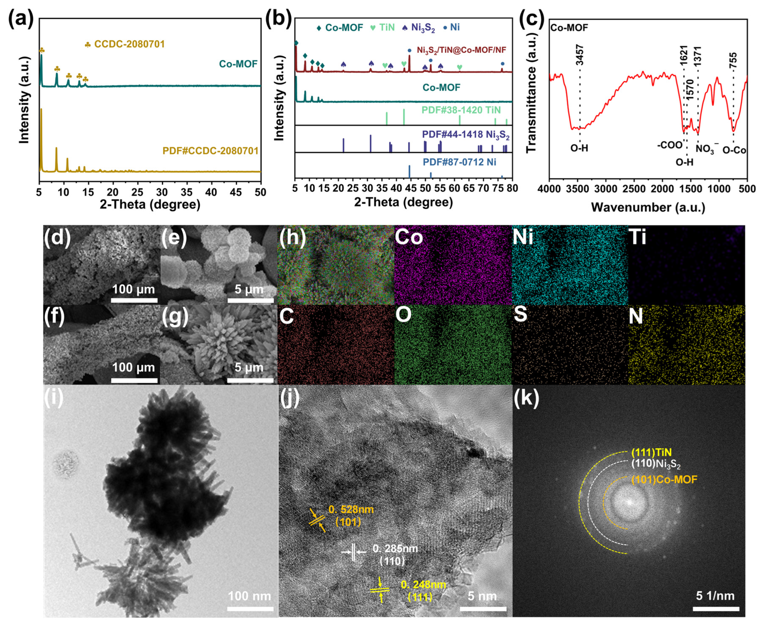
The samples Co-MOF and Ni3S2/TiN@Co-MOF/NF were tested by X-ray diffraction (XRD), as illustrated in Figure 1a. The Co-MOF samples were obtained by scraping the Co-MOF/NF samples, and the X-ray diffraction of the Co-MOF sampled at 5.40°, 8.50°, 10.68°, 13.10°, and 14.18° had obvious diffraction peaks. The diffraction angles of the sample were consistent with those of Co-MOF (CCDC-2080701), which correspond to the (101), (201), (321), (420), and (431) crystal planes of Co-MOF, respectively [38]. Diffraction peaks could be seen, as shown in the XRD diffraction pattern for the specimen depicted in Figure 1b at 44.51°, 51.84°, and 76.36°. These diffraction angles matched those of the nickel monomers (PDF# 87-0712), which correspond to (110), (200), and (220). Diffraction peaks were present at 21.71°, 31.12°, 38.33°, 49.72°, 50.14°, and 55.11°, and diffraction angles were consistent with those of Ni3S2 (PDF# 44-1418), which were related to the crystal planes designated as (101), (110), (021), (113), (211), and (122) [39]. The peaks were present at 29.81°, 33.42°, and 78.63°, with diffraction angles consistent with those of TiN (PDF#38-1420), which corresponded to the diffraction angles of TiN (PDF# 38-1420) at (111), (200), and (222) crystal planes, respectively. The results of XRD refinement of Co-MOF/NF and Ni3S2/TiN@Co-MOF/NF electrode materials show that after refinement, the fit is good (Figure S1), which also proves that the electrode materials have been successfully prepared, and the cell parameter data of the two are also obtained (Table S1).
For a more thorough investigation into the samples’ chemical bonding characteristics, Figure 1c displays the FTIR spectra for the Co-MOF/NF specimen. The spectral examination revealed distinct bands near 1570 cm−1 and 3457 cm−1, signifying the existence of O-H, and indicating that water molecules were present in the Co-MOF samples. The observation of a distinct band at 1371 cm−1 suggests erratic oscillations of NO3. This was further evidenced by the pronounced characteristics of the sample’s spectrum. The absorption band observed at 755 cm−1, which was more pronounced, was ascribed to the elongating vibrations of O-Co. Additionally, the maximum absorption peak observed at 1621 cm−1 aligns with -COO. This was further explained as resulting from the displacement of H3BTC’s proton by Co ions with -COO, culminating in the replacement of -COOH [40].
The samples underwent SEM and EDS examinations, focusing on their form and elemental configuration. Figure 1d along with Figure 1e illustrate the structure of the Co-MOF/NF substance, and in comparison to NF, it displays a consistent coating of spherulites on the surface. Figure 1f,g exhibit SEM pictures of Ni3S2/TiN@Co-MOF/NF. Compared with Co-MOF/NF, the surface was loaded with a more uniform layer of nanoflower-like material. This particular porous multilevel structure provided an expanded surface area [41]. Figure 1h exhibits the EDS images of Ni3S2/TiN@Co-MOF/NF samples, which could clearly demonstrate that the components of C, Co, O, Ni, S, Ti, and N are evenly dispersed. The specific content of each element is shown in Figure S2.
In an attempt to further investigate the microscopic morphology of Ni3S2/TiN@Co-MOF/NF, the materials were subjected to TEM tests. As shown in Figure 1i,j, the nanoflowers Ni3S2 and TiN were uniformly loaded on the spherical Co-MOF/NF, which formed an excellent porous multilevel structure, in addition to the good electrical conductivity of TiN, which further facilitated the ionic transport. HRTEM is shown in Figure 1k. The (101) crystalline surface [42] of Co-MOF, the (110) crystalline surface [43] of Ni3S2, and the (111) crystalline surface [44] of TiN all had clear debrided lattice edges, and the corresponding lattice spacings of the three sets of crystalline surfaces were d = 0.528 nm, d = 0.285 nm, and d = 0.248 nm, respectively.
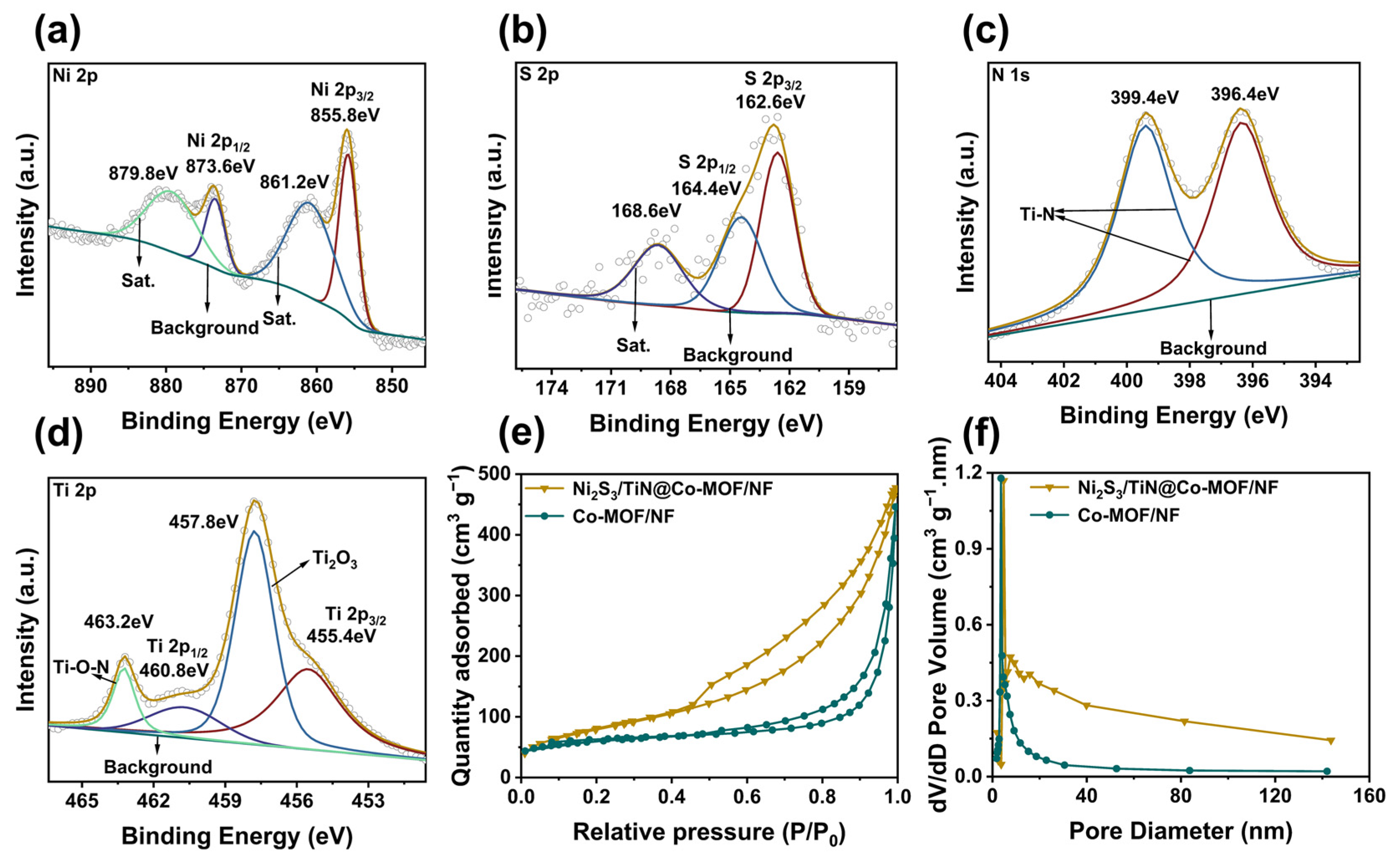
Figure S3a displayed the XPS for Co-MOF/NF, consisting of Co, C, and O. The XPS energy spectrum for Co 2p reveals that, respectively, the presence of Co3+ and Co2+ was suggested amidst the summits observed at 781.2 eV and 784.6 eV in Co 2p3/2; the detection of peaks at 797 eV and 801.8 eV also suggested the presence of Co3+ and Co2+ within Co 2p1/2, as illustrated in Figure S3b. In the energy spectrum, there were two peaks from satellites located at energies of 788.2 eV and 804.8 eV [45]. The BTC backbone, Co-MOF material, and COO-Co groups were responsible for the peaks in Figure S3c’s C 1s energy spectrum, which were positioned at energy levels of 284.6 eV, 286.4 eV, and 288.6 eV, respectively; the detected peaks matched up with the C=C, C-C, and O-C=O groups, indicating their presence [46]. It was evident through Figure S3d that the summits situated at 530.8 eV, 532.2 eV, and 533.6 eV in the energy spectrum of O 1s correspond to Ni-OH/C=O, O=N-O, and O=C-OH/C-OH functional groups, which was due to the metal–oxygen bonding, NO3 from the feedstock, and water molecules [47]. The XPS of Ni3S2/TiN@Co-MOF/NF was shown in Figure S4, containing elements Co, C, O, Ni, S, Ti, and N. From Figure 2a, evidently, the Ni 2p3/2 was identified by the peak at 855.8 eV, while the Ni 2p1/2 is marked by the 873.6 eV peak. Additionally, the satellite peaks were represented by the 861.2 eV and 879.8 eV peaks. As illustrated in Figure 2b, the XPS energy spectra of S 2p prominently displayed three distinct peaks. The energy levels were as follows: 162.6 eV corresponded to S 2p3/2, 164.4 eV corresponded to S 2p1/2, and 168.6 eV corresponded to satellite peaks [48]. In the energy spectrum of N 1S (Figure 2c), peaks noted were found at the binding energy locations of 396.4 eV and 399.4 eV, which were a result of the Ti-N bond [49]. The Ti 2p energy spectrum (Figure 2d) had four peaks: the energies 455.4 eV and 460.8 eV were associated with Ti 2p3/2 and Ti 2p1/2, respectively, while the values 457.8 eV and 463.2 eV were indicative of Ti2O3 and the Ti-O-N compound, which was due to the oxidation of TiN [50,51,52,53]. In summary, as shown above, Co-MOF/NF and Ni3S2/TiN@Co-MOF/NF were successfully prepared by combining the results of XRD, FTIR, SEM, EDS, TEM, and XPS analyses.
To obtain a more thorough understanding with reference to unique surface area and pore size features, the specimens underwent nitrogen adsorption and desorption examination. Furthermore, the Co-MOF/NF and Ni3S2/TiN@Co-MOF/NF exhibited N2 adsorption–desorption isotherms, as shown in Figure 2e, and typical type IV isotherms, with obvious capillary coalescence at higher P/P0. The desorption isotherms were located above the adsorption isotherms, which appeared as a hysteresis phenomenon. The desorption isotherm and adsorption isotherm did not overlap, resulting in the formation of hysteresis loops, which proves the existence of mesopores. The pore diameters of Co-MOF/NF and Ni3S2/TiN@Co-MOF/NF range from 5 nm to 140 nm, according to the pore size distributions with regard to the two materials (Figure 2f), and the average pore sizes were, respectively, 11.44 nm and 26.46 nm. Sufficient mesopores were highly favorable for electrolyte-to-electrode transport. The Co-MOF/NF and Ni3S2/TiN@Co-MOF/NF possess a porosity characterized by a unique surface area and porosities, with a surface area measuring 135.73 m2 g−1, and porosities measuring 0.33 cm3 g−1. Compared to Co-MOF/NF, Ni3S2/TiN@Co-MOF/NF demonstrates an extraordinary specific surface area and higher porosities, specifically 168.48 m2 g−1 and 0.42 cm3 g−1. Theoretically, this increase in surface area and porosity augments the number of reachable active sites, potentially owing to the incorporation of Ni3S2 and TiN to diminish the material’s natural agglomeration [54]. The investigation into the materials’ ability to conduct electricity involved testing them (referenced in Figure S5), revealing their conductivities to be 4.8 S cm−1 and 8.1 S cm−1, respectively, which is predominantly attributable to the introduction of TiN for the enhancement with regard to the material’s electrical conductivity. The enhancement in conductivity also improves electron movement during charging and discharging [55].

3.2. Assessment of Electrochemical Properties

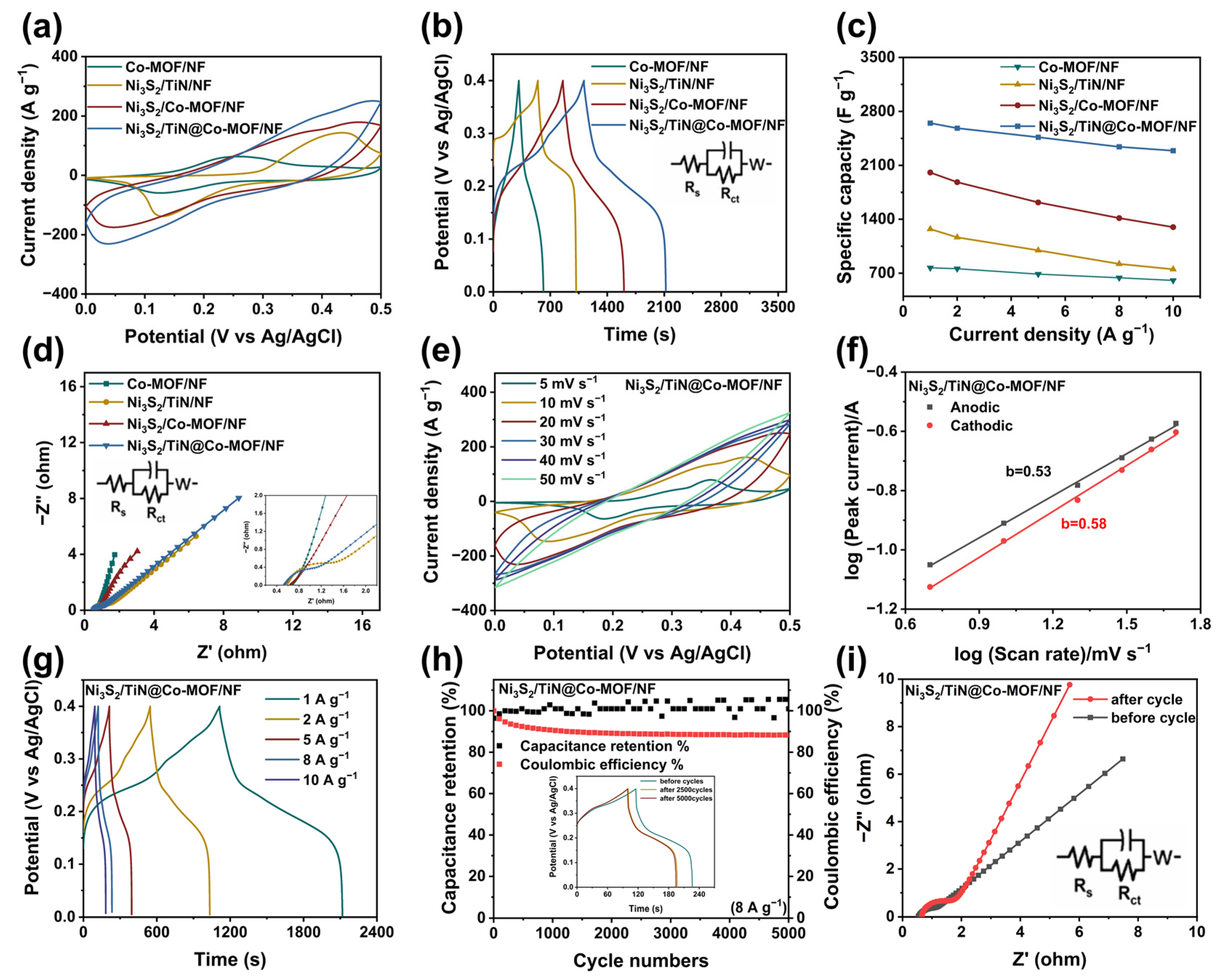
Pertaining to examining the electrochemical properties of Ni3S2/TiN@Co-MOF/NF composites, CV, GCD, and EIS tests were executed within the configuration of three electrodes. Figure 3a represents the four kinds of Co-based metal–organic frameworks/nickel foam (Co-MOF/NF) nickel sulfide/titanium nitride/nickel foam (Ni3S2/TiN/NF), nickel sulfide/Co-based metal–organic frameworks/nickel foam (Ni3S2/Co-MOF/NF), and nickel sulfide/titanium nitride@Co-based metal–organic frameworks/nickel foam (Ni3S2/TiN@Co-MOF/NF) operating during a scanning speed of 20 mV s−1. Material CV curve observations revealed that the CV curve for Ni3S2/TiN@Co-MOF/NF encompasses the most substantial area, which was preliminarily inferred as Ni3S2/TiN@Co-MOF/NF exhibiting a higher specific capacitance. Each curve exhibited a distinct redox peak, a result of the redox reaction involving the reactive substance regarding the electrode material. The emergence of the redox peak could be attributed to the ensuing reaction, leading to the deduction that the electrode substance was a pseudocapacitance material [56,57]:
Ni3S2 + OH ↔ Ni3S2OH + e
Co(II)-MOF + OH ↔ Co(III)-(OH)MOF + e
Figure 3b’s presentation of the GCD test further reinforces the derived conclusion. The GCD graph for Ni3S2/TiN@Co-MOF/NF also supported this. The most extended durations for discharging was combined with the greatest specific capacitance in cases where the density of the current was 1 A g−1. The specific capacitances of Co-MOF/NF, Ni3S2/TiN/NF, Ni3S2/Co-MOF/NF, and Ni3S2/TiN@Co-MOF/NF were 770.1 F g−1, 1272.3 F g−1, 2007.8 F g−1, and 2648.8 F g−1. The energy efficiency of the Ni3S2/TiN@Co-MOF/NF electrode material is 91% (1 A g−1). Figure 3c displays performance graphs for the magnification of the four substances at varying current densities. When operating with a current density of 10 A g−1, the observed specific capacitance measurements were 606.3 F g−1, 751.2 F g−1, 1297.1 F g−1, and 2290.5 F g−1, which were observed to retain 78.1%, 59.7%, 64.6%, and 86.5% of their original capacity, respectively. In a relative sense, a high specific capacitance belonging to the Ni3S2/TiN@Co-MOF/NF, even at high current densities, indicated that the material performs well electrochemically [58]. In an effort to be able to better investigate the microscopic particle dynamics of composite materials, EIS tests were carried out on four materials within the range of frequencies extending from 1 Hz to 100 KHz. The EIS trajectories depicted in Figure 3d show two distinct categories, a semicircle and a rectilinear line, where the half-circle symbolizes the high-frequency area and the rectilinear line denotes the low-frequency zone. The magnitude of the equivalent series resistance (Rs) was indicated by the horizontal axis’s coordinate at the curve’s first point of intersection, primarily linked to electrode material and solution resistance, while the semicircle’s width signified the resistance to transfer of charge (Rct); this primarily refers to the opposition encountered in the transfer of charge during redox processes [59]. The analysis showed that the Rs for the four materials were 0.681, 0.566, 0.615, and 0.526; the corresponding Rct numerals are 4.62, 0.54, 0.91, and 0.31, respectively. Reduced Rs and Rct numerically in Ni3S2/TiN@Co-MOF/NF suggested an enhanced charge movement between the electrode and electrolyte solutions. This might stem from Ni3S2/TiN@Co MOF/NF’s distinct shape and TiN’s effective electrical conductivity. Lower Rct values also contributed to the electrode material’s redox reaction, enhancing its electrochemical efficiency.
To investigate the electrochemical properties of Ni3S2/TiN@Co-MOF/NF more deeply, the electrode materials underwent CV experiments at varying scanning rates, which span from 5 mV s−1 to 50 mV s−1, as depicted in Figure 3e; clearly, accompanied by an increase in the rate of scanning, the redox peaks of the CV curves moved [60,61]. The cause was the hastened rate of scanning on the exterior layer of the electrode substances; the redox reaction could not sufficiently occur, and the current growth rate increased while the redox reaction rate was relatively slow. The redox peaks shifted because the materials could not be transformed in time [62]. The pseudocapacitance energy storage mechanism was separated into surface control and diffusion control. Surface control refers to the electrode material’s capacity to absorb and release charge, while diffusion control involves the process of reversible oxidation at the active site through charge movement. As depicted in Figure 3f, graphs depicting scan rates and peak current were produced through the analysis of the CV curves for Ni3S2/TiN@Co-MOF/NF materials, aiming to understand how both control mechanisms affect charge storage capacity. The correlation between the scanning speed (v) and the peak current (i) was i = avb (a and b are constants) and taking the logarithm of both sides at the same time yields Iog(i) = blog(v) + log(a); when b=0.5 was the diffusion control and when b=1 was the surface control. The material’s predicted oxidation peak was observed at b equal to 0.53, and the reduction peak occurred at a value of 0.53 for b, which was closer to 0.5, suggesting that the material’s charge storage had primarily been regulated by diffusion [63,64].
Figure 3g illustrates the curves of Ni3S2/TiN@Co-MOF/NF GCD at different electrical densities. By modifying the current intensities to levels (1 A g−1–10 A g−1), the distinct specific capacitances for the electrode material were 2648.8 F g−1, 2582 F g−1, 2465.5 F g−1, 2340.3 F g−1, and 2290.9 F g−1. Results from the 2290.9 F g−1 research indicated that increased current densities maintained an elevated specific capacitance. The steadiness of Ni3S2/TiN@Co-MOF/NF following multiple charging and discharging phases was assessed through a steady current charging and discharging experiment conducted over 5000 rotations when the current density reached 8 A g−1. The examination resulted in a distinct rate at which capacitance was retained at 88.3%, as depicted in Figure 3h. The Coulomb efficiency after the cycle is close to 101% (8 A g−1). The degradation of electrochemical properties post-cycle could be ascribed to the shedding and reduction of active materials. From Figure 3i, after the cycle test, it was evident that the material’s charge transfer resistance (Rct) increased, which might further demonstrate that the material’s performance had declined [65]. Compared with the materials in Table S2, Ni3S2/TiN@Co-MOF/NF materials had better specific capacity and cycling stability.

3.3. Electrochemical Measurements of Non-Symmetrical Supercapacitor (ASC)

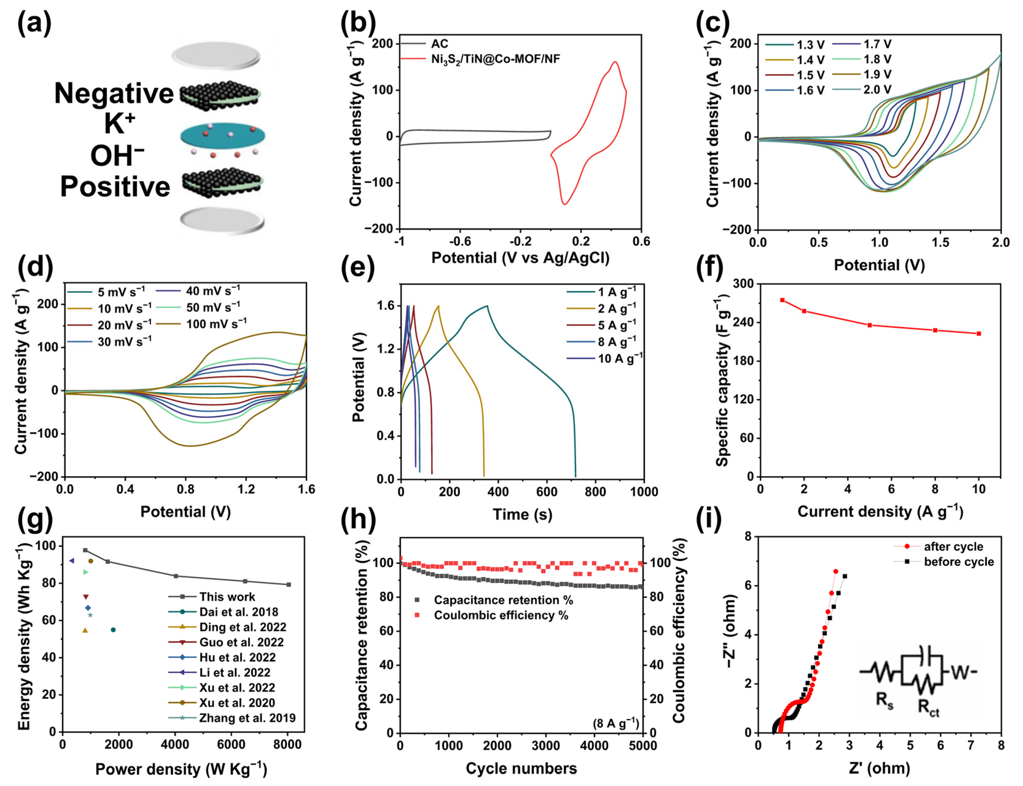
In Ni3S2/TiN@Co-MOF/NF supercapacitors (Figure 4a), the positive electrode was Ni3S2/TiN@Co-MOF/NF, and the AC in the capacitor served as the negative electrode, while the electrolyte consisted of 3 M KOH, it assembled into Ni3S2/TiN@Co-MOF/NF//AC asymmetric supercapacitors (ASCs). Using different materials for the capacitor’s electrodes, both positive and negative, could effectively enhance its electrochemical performance.
Testing of the AC electrode material through CV, GCD, and EIS involved a tri-electrode system, utilizing a 3 M KOH solution for electrolytes, Ag/AgCl as the benchmark electrode, platinum sheeted for counter electrodes, and AC for the working electrode. Figure S6a exhibits CV display curves at varying scanning speeds. Evidently, the curves did not have prominent redox peaks, which can be judged as a typical electric double-layer capacitance behavior. The GCD curves in Figure S6b also proved this point of view because the curves did not display straightforward charging and discharging platforms, which were approximated as triangles. Moreover, the recorded specific capacitances for activated carbon were as follows: with a current density of 1 A g−1, the figure stands at 128.8 F g−1; at 2 A g−1, it decreases slightly to 122.6 F g−1, further diminishing to 113.5 F g−1 at 5 A g−1; and it continues to drop to 109.3 F g−1 at 8 A g−1, and ultimately arches a current density of 10 A g−1 at 106.9 F g−1. This sequence demonstrates how specific capacitance varies with increasing current densities. The findings in Figure S6c displayed in the magnification performance curves signify that the AC material exhibits a minor reduction in specific capacitance, demonstrated by maintaining 82.8% (10 A g−1) of the capacitance. This suggests the material’s ability to retain a significant portion of its capacitance under high-current conditions and its excellent stability. Figure S6d shows the EIS curve, which indicates that the Rs of the AC is 0.32 and Rct is 0.17, which offered good conductivity performance and helped in electron transfer.
Figure 4b illustrates the cyclic voltammograms of both Ni3S2/TiN@Co-MOF/NF and activated carbon, configured within a trio of electrodes system, and captured using a scanning velocity of 10 mV s−1. This suggests that the voltage span extends between 0 V and 0.5 V for Ni3S2/TiN@Co-MOF/NF and from −1 V to 0 V for AC. Figure 4c illustrates that, over the interval where the voltage fluctuated within a range of 0 V to 1.6 V, the rate at which scanning was conducted was 50 mV s−1; there was no apparent polarization phenomenon, and when it was 1.7 V–2.0 V, the polarization phenomenon was gradually evident, and so to avoid the occurrence of the polarization phenomenon, the ideal voltage range of 1.6 V was chosen as the value.
To conduct the CV experiment for the ASC inside the optimal voltage spectrum of 1.6 V, various scan speeds were applied (as shown in Figure 4d). Elevating the scanning velocity to 100 mV s−1 seemed to have a lesser impact on the curve shapes. The stability was maintained well. It was evident from the data presented. Figure 4e displays the GCD graphs for various current densities. This encompasses capacities such as 1 A g−1–10 A g−1. The ASC demonstrates specific capacitances measured at values of 275.7 F g−1, 258.4 F g−1, 236.2 F g−1, 228.9 F g−1, and 222.7 F g−1. The energy efficiency of the ASC is 102% (1 A g−1). Additionally, these measurements were taken at an elevated current density measured at 10 A g−1. It displayed notably impressive results, retaining 81% of its performance, as shown in Figure 4f. This was illustrated in the context of the ASC’s Ragone plot (Figure 4g) as measuring power and energy densities was vital for assessing supercapacitors’ efficacy in practical scenarios. The outcomes presented an energy density of 97.8 W h kg−1 at 801.8 W kg−1 and 79.3 W h kg−1 at 8041.6 W kg−1. This marks a notable enhancement compared to the two essential parameters of supercapacitor power density and energy density mentioned in pertinent studies [66,67,68,69,70,71,72,73]. Figure 4h displays the ASC’s charge/discharge cycle test graph. The current’s density was measured at 8 A g−1. Clearly, after undergoing a total of 5000 cycles that include processes of both charging and draining, the ASC maintained a specific capacitance of 85.87%, showcasing its remarkable stability. The Coulomb efficiency after the cycle was close to 99%. Figure 4i shows the EIS curves before and after 5000 charge/discharge cycles, which shows that compared to before cycling, the Rs and Rct after cycling become more extensive, which may be caused by the structural changes due to the reduction of active substances after cycling [74]. In order to verify the practical application effect of ACS, the assembled ACS device lit up the red light-emitting diode (LED) and maintained a high brightness after 120 s (Figure S7a). After the red LED was lit, the GCD charging test was carried out on the ASC and it was found that it could still reach the level of 1.6V, which demonstrates its good voltage-holding ability (Figure S7b).

4. Conclusions

In this paper, the Ni3S2/TiN@Co-MOF/NF electrode was prepared by a bi-step hydrothermal technique. The specific capacitance and conductivity of the Co-MOF/NF electrode were significantly improved after the introduction of Ni3S2 and TiN. The electrode material composed of Ni3S2/TiN@Co-MOF/NF exhibited outstanding electrochemical properties: the specific capacitances were 2648.8 F g−1 and 2290.9 F g−1 at the current densities of 1 A g−1 and 10 A g−1, respectively. Moreover, it displayed a notably high rate of performance (retaining 86.5%). Interestingly, the assembled ASC retained 85.87% of its specific capacitance after 5000 cycles, indicating its excellent cycle stability. It displayed a measurement of energy density at 97.8 W h kg−1 and a power density of 801.8 W kg−1. Therefore, the work presents a simple strategy for the fabrication of electrodes in supercapacitor practical applications.

Supplementary Materials

The following supporting information can be downloaded at: https://www.mdpi.com/article/10.3390/en17112788/s1, Figure S1. (a,b) XRD refinement of Co-MOF/NF and Ni3S2/TiN@Co-MOF/NF. Figure S2. Tomic percentage (%) for Ni3S2/TiN@Co-MOF/NF. Figure S3. XPS of Co-MOF/NF. (a) Total Spectrum. (b) Co. (c) C. (d) O. Figure S4. total spectrum of XPS of Ni3S2/TiN@Co-MOF/NF. Figure S5. electrical conductivity of Ni3S2/TiN@Co-MOF/NF. Figure S6. (a) CV of AC. (b) GCD of AC (c) Specific capacity retention of AV. (d) Nernquist curves of AC. Figure S7. (a) A red led powered by the assembled ASC device lights up the photo for 120 s. (b) GCD curves for the charging of the ACS device. Table S1. Cell parameters of Co-MOF/NF and Ni3S2/TiN@Co-MOF/NF. Table S2. Comparison of the performance of different electrodes under three electrode systems. References [75,76,77,78,79,80,81,82,83,84] are cited in the supplementary materials.

Author Contributions

N.Z.: Drafted and edited manuscripts, conducted experiments, processed and analyzed data. J.W. and S.W.: data analysis, article review, and material characterization. Q.K. and Z.L.: data analysis, idea discussion, and paper review. X.T.: data analysis and paper review. R.X. and L.Y.: talking about study of ideas, editing process, and assessing manuscript. All authors have read and agreed to the published version of the manuscript.

Funding

The authors gratefully acknowledge the National Natural Science Foundation of China (Project Nos. 22262017) and the Yunnan Fundamental Research Projects (Grant no. 202301AT070399).

Data Availability Statement

The raw data supporting the conclusions of this article will be made available by the authors on request.

Conflicts of Interest

The authors declare no conflict of interest.

References

  1. Libich, J.; Sedlaříková, M.; Máca, J.; Čudek, P.; Kazda, T.; Fafilek, G.; Rodríguez; Batteries, J.J.S. Supercapacitors vs. Lithium-ion Batteries: Properties and Applications. Chem. Ing. Tech. 2023, 29, 279–285. [Google Scholar] [CrossRef]
  2. Pameté, E.; Köps, L.; Kreth, F.A.; Pohlmann, S.; Varzi, A.; Brousse, T.; Balducci, A.; Presser, V. The Many Deaths of Supercapacitors: Degradation, Aging, and Performance Fading. Adv. Energy Mater. 2023, 13, 2301008. [Google Scholar] [CrossRef]
  3. Zhou, T.; Cheng, Q. Chemical Strategies for Making Strong Graphene Materials. Angew. Chem. Int. Ed. 2021, 60, 18397–18410. [Google Scholar] [CrossRef] [PubMed]
  4. Ramachandran, T.; Sana, S.S.; Kumar, K.D.; Kumar, Y.A.; Hegazy, H.H.; Kim, S.C. Asymmetric supercapacitors: Unlocking the energy storage revolution. J. Energy Storage 2023, 70, 109096. [Google Scholar] [CrossRef]
  5. Shah, S.S.; Niaz, F.; Ehsan, M.A.; Das, H.T.; Younas, M.; Khan, A.S.; Rahman, H.U.; Nayem, S.M.A.; Oyama, M.; Aziz, M.A. Advanced strategies in electrode engineering and nanomaterial modifications for supercapacitor performance enhancement: A comprehensive review. J. Energy Storage 2024, 79, 110152. [Google Scholar] [CrossRef]
  6. Pandey, D.; Kumar, K.S.; Thomas, J. Supercapacitor electrode energetics and mechanism of operation: Uncovering the voltage window. Prog. Mater. Sci. 2024, 141, 101219. [Google Scholar] [CrossRef]
  7. Benjamin, M.; Manoj, D.; Karnan, M.; Saravanakumar, D.; Thenmozhi, K.; Ariga, K.; Sathish, M.; Senthilkumar, S. Switching the solubility of electroactive ionic liquids for designing high energy supercapacitor and low potential biosensor. J. Colloid Interface Sci. 2021, 588, 221–231. [Google Scholar] [CrossRef] [PubMed]
  8. Dong, W.; Xie, M.; Zhao, S.; Qin, Q.; Huang, F. Materials design and preparation for high energy density and high power density electrochemical supercapacitors. Mater. Sci. Eng. R Rep. 2023, 152, 100713. [Google Scholar] [CrossRef]
  9. Meena, D.; Kumar, R.; Gupta, S.; Khan, O.; Gupta, D.; Singh, M. Energy storage in the 21st century: A comprehensive review on factors enhancing the next-generation supercapacitor mechanisms. J. Energy Storage 2023, 72, 109323. [Google Scholar] [CrossRef]
  10. Khan, A.J.; Gao, L.; Sajjad, M.; Khan, S.; Mateen, A.; Ghaffar, A.; Malik, I.A.; Liao, X.; Zhao, G. Synthesis of heterostructured ZnO-CeO2 nanocomposite for supercapacitor applications. Inorg. Chem. Commun. 2024, 159, 111794. [Google Scholar] [CrossRef]
  11. Khan, A.J.; Sajjad, M.; Khan, S.; Khan, M.; Mateen, A.; Shah, S.S.; Arshid; Gao, Z. Telluride-Based Materials: A Promising Route for High Performance Supercapacitors. Chem. Rec. 2024, 24, e202300302. [Google Scholar] [CrossRef] [PubMed]
  12. Lamba, P.; Singh, P.; Singh, P.; Singh, P.; Bharti; Kumar, A.; Gupta, M.; Kumar, Y. Recent advancements in supercapacitors based on different electrode materials: Classifications, synthesis methods and comparative performance. J. Energy Storage 2022, 48, 103871. [Google Scholar] [CrossRef]
  13. Molahalli, V.; Chaithrashree, K.; Singh, M.K.; Agrawal, M.; Krishnan, S.G.; Hegde, G. Past decade of supercapacitor research—Lessons learned for future innovations. J. Energy Storage 2023, 70, 108062. [Google Scholar] [CrossRef]
  14. Shaheen, I.; Hussain, I.; Zahra, T.; Javed, M.S.; Shah, S.S.A.; Khan, K.; Hanif, M.B.; Assiri, M.A.; Said, Z.; Arifeen, W.U.; et al. Recent advancements in metal oxides for energy storage materials: Design, classification, and electrodes configuration of supercapacitor. J. Energy Storage 2023, 72, 108719. [Google Scholar] [CrossRef]
  15. Du, W.; Bai, Y.-L.; Xu, J.; Zhao, H.; Zhang, L.; Li, X.; Zhang, J. Advanced metal-organic frameworks (MOFs) and their derived electrode materials for supercapacitors. J. Power Sources 2018, 402, 281–295. [Google Scholar] [CrossRef]
  16. Senthil, R.A.; Osman, S.; Pan, J.; Liu, X.; Wu, Y. Recent progress on porous carbon derived from Zn and Al based metal-organic frameworks as advanced materials for supercapacitor applications. J. Energy Storage 2021, 44, 103263. [Google Scholar]
  17. Akkinepally, B.; Kumar, G.D.; Reddy, I.; Rao, H.; Nagajyothi, P.C.; Alothman, A.A.; Alqahtani, K.N.; Hassan, A.M.; Javed, M.S.; Shim, J. Investigation of Supercapacitor Electrodes Based on MIL-101(Fe) Metal-Organic Framework: Evaluating Electrochemical Performance through Hydrothermal and Microwave-Assisted Synthesis. Crystals 2023, 13, 1547. [Google Scholar] [CrossRef]
  18. Yue, L.; Chen, L.; Wang, X.; Lu, D.; Zhou, W.; Shen, D.; Yang, Q.; Xiao, S.; Li, Y. Ni/Co-MOF@aminated MXene hierarchical electrodes for high-stability supercapacitors. Chem. Eng. J. 2023, 451, 138687. [Google Scholar]
  19. Wang, G.; Yan, Z.; Wang, N.; Xiang, M.; Xu, Z. NiO/Ni Metal–Organic Framework Nanostructures for Asymmetric Supercapacitors. ACS Appl. Nano Mater. 2021, 4, 9034–9043. [Google Scholar] [CrossRef]
  20. Ajdari, F.A.; Kowsari, E.; Shahrak, M.N.; Ehsani, A.; Kiaei, Z.; Torkzaban, H.; Ershadi, M.; Eshkalak, S.K.; Haddadi-Asl, V.; Chinnappan, A.; et al. A review on the field patents and recent developments over the application of metal organic frameworks (MOFs) in supercapacitors. Coord. Chem. Rev. 2020, 422, 213441. [Google Scholar] [CrossRef]
  21. Qin, P.; Huang, C.; Gao, B.; Pi, C.; Fu, J.; Zhang, X.; Huo, K.; Chu, P.K. Ultrathin carbon layer-encapsulated TiN nanotubes array with enhanced capacitance and electrochemical stability for supercapacitors. Appl. Surf. Sci. 2020, 503, 144293. [Google Scholar] [CrossRef]
  22. Zhao, F.; Gong, Q.; Traynor, B.; Zhang, D.; Li, J.; Ye, H.; Che, F.; Han, N.; Wang, Y.; Sun, X.; et al. Stabilizing nickel sulfide nanoparticles with an ultrathin carbon layer for improved cycling performance in sodium ion batteries. Nano Res. 2016, 9, 3162–3170. [Google Scholar] [CrossRef]
  23. Kim, J.; Ahn, H.; Ryu, H.; Kim, D.; Cho, G.; Kim, K.; Nam, T.; Ahn, J.H. The discharge properties of Na/Ni3S2 cell at ambient temperature. J. Power Sources 2008, 178, 852–856. [Google Scholar] [CrossRef]
  24. Li, J.; Deng, Z.; Liu, C.; Rong, H.; Zeng, Z. TiN nano arrays on nickel foam prepared by multi-arc ion plating for fast-charging supercapacitors. Appl. Surf. Sci. 2022, 593, 153360. [Google Scholar] [CrossRef]
  25. Qu, Y.; Sun, L.; Xie, F.; Hu, J.; Tan, H.; Qian, J.; Shi, X.; Zhang, Y. Tuning the crystal structure of NiS/carbon by Mo doping for asymmetric supercapacitor application. Mater. Today Chem. 2022, 26, 101188. [Google Scholar] [CrossRef]
  26. Peng, X.; Huo, K.; Fu, J.; Gao, B.; Wang, L.; Hu, L. Porous Dual-Layered MoOx Nanotube Arrays with Highly Conductive TiN Cores for Supercapacitors. ChemElectroChem 2015, 2, 512–517. [Google Scholar] [CrossRef]
  27. Zhang, J.; Li, Y.; Han, M.; Xia, Q.; Chen, Q.; Chen, M. Constructing ultra-thin Ni-MOF@NiS2 nanosheets arrays derived from metal organic frameworks for advanced all-solid-state asymmetric supercapacitor. Mater. Res. Bull. 2021, 137, 111186. [Google Scholar] [CrossRef]
  28. Bhagwan, J.; Han, J.I. Formation of MWCNT/LiCo2O4 nanoplates and their application for hybrid supercapacitor. Ceram. Int. 2024, 50, 10676–10687. [Google Scholar] [CrossRef]
  29. Li, K.; Li, S.; Huang, F.; Lu, Y.; Wang, L.; Chen, H.; Zhang, H. Hydrothermally formed three-dimensional hexagon-like P doped Ni(OH)2 rod arrays for high performance all-solid-state asymmetric supercapacitors. Appl. Surf. Sci. 2018, 428, 250–257. [Google Scholar] [CrossRef]
  30. Arbizzani, C.; Yu, Y.; Li, J.; Xiao, J.; Xiao, Y.; Yang, Y.; Santato, C.; Raccichini, R.; Passerini, S. Good practice guide for papers on supercapacitors and related hybrid capacitors for the Journal of Power Sources. J. Power Sources 2020, 450, 227636. [Google Scholar] [CrossRef]
  31. Hu, C.; Miao, L.; Yang, Q.; Yu, X.; Song, L.; Zheng, Y.; Wang, C.; Li, L.; Zhu, L.; Cao, X.; et al. Self-assembly of CNTs on Ni foam for enhanced performance of NiCoO2@CNT@NF supercapacitor electrode. Chem. Eng. J. 2021, 410, 128317. [Google Scholar] [CrossRef]
  32. Huang, C.; Lv, S.; Gao, A.; Ling, J.; Yi, F.; Hao, J.; Wang, M.; Luo, Z.; Shu, D. Boosting the energy density of supercapacitors by designing both hollow NiO nanoparticles/nitrogen-doped carbon cathode and nitrogen-doped carbon anode from the same precursor. Chem. Eng. J. 2022, 431, 134083. [Google Scholar] [CrossRef]
  33. Ren, F.; Lu, Z.; Liu, X.; Wang, T.; Huang, X.; Dou, J.; Wu, D.; Yu, J.; Chen, X. Lewis acid-etched MXene self-assembled with reduced graphene oxide for symmetrical supercapacitors with liquid/ solid electrolytes. J. Alloys Compd. 2024, 978, 173480. [Google Scholar] [CrossRef]
  34. Chen, F.; Liu, C.; Cui, B.; Dou, S.; Xu, J.; Liu, S.; Zhang, H.; Deng, Y.; Chen, Y.; Hu, W. Regulated synthesis of Eutectic Ni3S2/NiS nanorods for quasi-solid-state hybrid supercapacitors with high energy density. J. Power Sources 2021, 482, 228910. [Google Scholar] [CrossRef]
  35. Phonsuksawang, P.; Khajondetchairit, P.; Ngamchuea, K.; Butburee, T.; Sattayaporn, S.; Chanlek, N.; Suthirakun, S.; Siritanon, T. Enhancing performance of NiCo2S4/Ni3S2 supercapacitor electrode by Mn doping. Electrochim. Acta 2021, 368, 137634. [Google Scholar] [CrossRef]
  36. Wang, J.; Chao, D.; Liu, J.; Li, L.; Lai, L.; Lin, J.; Shen, Z. Ni3S2@MoS2 core/shell nanorod arrays on Ni foam for high-performance electrochemical energy storage. Nano Energy 2014, 7, 151–160. [Google Scholar] [CrossRef]
  37. Yue, H.; Du, H.; Ma, X.; Zhang, X. Honeycomb-like Ni3(NO3)2(OH)4@Ni/Co-BTC composites as electrode materials for high performance supercapacitors. Mater. Sci. Eng. B 2021, 268, 115136. [Google Scholar] [CrossRef]
  38. Liu, Q.; Zhang, L.; Bao, Y.; Zhang, N.; Zhang, J.; Xing, Y.; Deng, W.; Liu, Z. Structures and catalytic oxidative coupling reaction of four Co-MOFs modified with R-isophthalic acid (R=H, OH and COOH) and trigonal ligands. CrystEngComm 2021, 23, 7590–7601. [Google Scholar] [CrossRef]
  39. Liu, X.; Wang, J.; Hu, N.; Liao, J.; Zong, N.; Wei, J.; Li, M.; Wang, L.; Xu, R.; Yang, L. Facile synthesis of neuronal nickel–cobalt manganese sulfide for asymmetric supercapacitors with excellent energy density. J. Electroanal. Chem. 2023, 932, 11726. [Google Scholar] [CrossRef]
  40. Zhao, T.; Jiang, H.; Ma, J. Surfactant-assisted electrochemical deposition of α-cobalt hydroxide for supercapacitors. J. Power Sources 2011, 196, 860–864. [Google Scholar] [CrossRef]
  41. Ren, C.; Jia, X.; Zhang, W.; Hou, D.; Xia, Z.; Huang, D.; Hu, J.; Chen, S.; Gao, S. Hierarchical Porous Integrated Co1−xS/CoFe2O4@rGO Nanoflowers Fabricated via Temperature-Controlled In Situ Calcining Sulfurization of Multivariate CoFe-MOF-74@rGO for High-Performance Supercapacitor. Adv. Funct. Mater. 2020, 30, 2004519. [Google Scholar] [CrossRef]
  42. Gurav, S.R.; Chodankar, G.R.; Sawant, S.A.; Shembade, U.V.; Moholkar, A.V.; Sonkawade, R.G. Exploring the potential of simultaneous nanoarchitectonics and utilization of Co-MOFs electrode as well as powder for aqueous supercapacitors. J. Energy Storage 2023, 73, 109254. [Google Scholar] [CrossRef]
  43. Qian, H.; Wu, B.; Nie, Z.; Liu, T.; Liu, P.; He, H.; Wu, J.; Chen, Z.; Chen, S. A flexible Ni3S2/Ni@CC electrode for high-performance battery-like supercapacitor and efficient oxygen evolution reaction. Chem. Eng. J. 2021, 420, 127646. [Google Scholar] [CrossRef]
  44. Feng, S.; Yang, L.; Deng, P.; Wang, J.; Xu, R.; Liu, X.; Wang, W.; Tian, X.; Wu, Z. Hierarchical self-supported NiSe2/TiN@Ni12P5 on nickel foam for the urea oxidation reaction. Int. J. Hydrog. Energy 2022, 47, 36814–36822. [Google Scholar] [CrossRef]
  45. Ko, S.; Tang, X.; Gao, F.; Wang, C.; Liu, H.; Liu, Y. Selective catalytic reduction of NOx with NH3 on Mn, Co-BTC-derived catalysts: Influence of thermal treatment temperature. J. Solid State Chem. 2022, 307, 122843. [Google Scholar] [CrossRef]
  46. Zha, X.; Shi, L.; Yang, Y. In situ vertically growth of 2D NiCo-BTC nanosheet arrays for binder-free flexible wearable energy storage devices. J. Energy Storage 2023, 60, 106578. [Google Scholar] [CrossRef]
  47. Rong, H.; Chen, T.; Shi, R.; Zhang, Y.; Wang, Z. Hierarchical NiCo2O4@NiCo2S4 Nanocomposite on Ni Foam as an Electrode for Hybrid Supercapacitors. ACS Omega 2018, 3, 5634–5642. [Google Scholar] [CrossRef] [PubMed]
  48. Tao, K.; Gong, Y.; Lin, J. Epitaxial grown self-supporting NiSe/Ni3S2/Ni12P5 vertical nanofiber arrays on Ni foam for high performance supercapacitor: Matched exposed facets and re-distribution of electron density. Nano Energy 2019, 55, 65–81. [Google Scholar] [CrossRef]
  49. Le, T.-L.T.; Nguyen, L.T.; Nguyen, H.-H.; Nghia, N.V.; Vuong, N.M.; Hieu, H.N.; Thang, N.V.; Le, V.T.; Nguyen, V.H.; Lin, P.-C.; et al. Titanium Nitride Nanodonuts Synthesized from Natural Ilmenite Ore as a Novel and Efficient Thermoplasmonic Material. Nanomaterials 2021, 11, 76. [Google Scholar]
  50. Guo, D.; Wan, Z.; Li, Y.; Xi, B.; Wang, C. TiN@Co5.47N Composite Material Constructed by Atomic Layer Deposition as Reliable Electrocatalyst for Oxygen Evolution Reaction. Adv. Funct. Mater. 2021, 31, 2008511. [Google Scholar] [CrossRef]
  51. Han, M.; Yang, J.; Jiang, J.; Jing, R.; Ren, S.; Yan, C. Efficient tuning the electronic structure of N-doped Ti-based MXene to enhance hydrogen evolution reaction. J. Colloid Interface Sci. 2021, 582, 1099–1106. [Google Scholar] [CrossRef]
  52. Shi, H.; Zhang, H.; Chen, Z.; Wang, T.; Wang, L.; Zeng, W.; Zhang, G.; Duan, H. Synthesis of TiN nanostructures by Mg-assisted nitriding TiO2 in N2 for lithium ion storage. Chem. Eng. J. 2018, 336, 12–19. [Google Scholar] [CrossRef]
  53. Sun, N.; Zhou, D.; Shi, S.; Liu, F.; Liu, W.; Chen, Q.; Zhao, P.; Li, S.; Wang, J. Superior-performance TiN films sputtered for capacitor electrodes. J. Mater. Sci. 2019, 54, 10346–10354. [Google Scholar] [CrossRef]
  54. Sun, J.; Gao, W.; Fei, H.; Zhao, G. Efficient and selective electrochemical reduction of nitrate to N2 by relay catalytic effects of Fe-Ni bimetallic sites on MOF-derived structure. Appl. Catal. B Environ. 2022, 301, 120829. [Google Scholar] [CrossRef]
  55. Wu, Y.; Hu, H.; Yuan, C.; Song, J.; Wu, M. Electrons/ions dual transport channels design: Concurrently tuning interlayer conductivity and space within re-stacked few-layered MXenes film electrodes for high-areal-capacitance stretchable micro-supercapacitor-arrays. Nano Energy 2020, 74, 104812. [Google Scholar] [CrossRef]
  56. Qin, Y.; Lyu, Y.; Chen, M.; Lu, Y.; Qi, P.; Wu, H.; Sheng, Z.; Gan, X.; Chen, Z.; Tang, Y. Nitrogen-doped Ni2P/Ni12P5/Ni3S2 three-phase heterostructure arrays with ultrahigh areal capacitance for high-performance asymmetric supercapacitor. Electrochim. Acta 2021, 393, 139059. [Google Scholar] [CrossRef]
  57. Yu, Q.; Gong, J.; Kong, W.; Long, Y.; Chen, J.; Pu, L.; Zhang, H.; Dai, Y. Preparation of NiAl LDH@Mn3O4@Co-MOF ternary composites using MOFs as a framework for high-performance asymmetric supercapacitors. Electrochim. Acta 2022, 428, 140913. [Google Scholar] [CrossRef]
  58. Khadka, A.; Samuel, E.; Pradhan, S.; Joshi, B.; Aldalbahi, A.; El-Newehy, M.; Lee, H.-S.; Yoon, S.S. Hydrothermal growth of FeMoO4 nanosheets on electrospun carbon nanofibers as freestanding supercapacitor electrodes. Ceram. Int. 2024, 50, 9398–9406. [Google Scholar] [CrossRef]
  59. Ramesh, S.; Bathula, C.; Ahmed, A.T.A.; Haldorai, Y.; Vijay, K.; Karthikeyan, C.; Selvaraj, M.; Shin, K.; Lee, Y.J.; Kim, H.-S.; et al. Nanostructurally fabrication of nickel oxide-interfaced carbon nanotubes for supercapacitors and exploration of electrochemical correlation via computer vision techniques and artificial intelligence. J. Energy Storage 2024, 82, 110429. [Google Scholar] [CrossRef]
  60. Zhao, F.; Zhang, S.; Wong, S.; Andrei, C.; Yuan, H.; Zhou, J.; Wang, J.; Zhuo, Z.; Zhong, Y.; Su, H.; et al. Revealing unprecedented cathode interface behavior in all-solid-state batteries with oxychloride solid electrolytes†. Energy Environ. Sci. 2024. [Google Scholar] [CrossRef]
  61. Zhao, F.; Wang, Y.; Xu, X.; Liu, Y.; Song, R.; Lu, G.; Li, Y. Cobalt Hexacyanoferrate Nanoparticles as a High-Rate and Ultra-Stable Supercapacitor Electrode Material. ACS Appl. Mater. Interfaces 2014, 6, 11007–11012. [Google Scholar] [CrossRef] [PubMed]
  62. Babu, C.R.; Avani, A.V.; Xavier, T.S.; Tomy, M.; Shaji, S.; Anila, E.I. Symmetric supercapacitor based on Co3O4 nanoparticles with an improved specific capacitance and energy density. J. Energy Storage 2024, 80, 110382. [Google Scholar] [CrossRef]
  63. Liu, H.; Yao, Z.; Liu, Y.; Diao, Y.; Hu, G.; Zhang, Q.; Li, Z. In situ synthesis of nitrogen site activated cobalt sulfide@N, S dual-doped carbon composite for a high-performance asymmetric supercapacitor. J. Colloid Interface Sci. 2021, 585, 30–42. [Google Scholar] [CrossRef] [PubMed]
  64. Mohan, V.V.; Mohan, M.; Rakhi, R.B. High performance supercapacitors based on WS2 nanoflower electrodes with commercial-level mass-loading. Surf. Interfaces 2023, 42, 103496. [Google Scholar] [CrossRef]
  65. Varghese, S.M.; Mohan, V.V.; Suresh, S.; Gowd, E.B.; Rakhi, R.B. Synergistically modified Ti3C2Tx MXene conducting polymer nanocomposites as efficient electrode materials for supercapacitors. J. Alloys Compd. 2024, 973, 172923. [Google Scholar] [CrossRef]
  66. Dai, S.; Liu, Z.; Zhao, B.; Zeng, J.; Hu, H.; Zhang, Q.; Chen, D.; Qu, C.; Dang, D.; Liu, M. A high-performance supercapacitor electrode based on N-doped porous graphene. J. Power Sources 2018, 387, 43–48. [Google Scholar] [CrossRef]
  67. Ding, S.; An, J.; Ding, D.; Zou, Y.; Zhao, L. Micron-sized NiMn-glycerate solid spheres as cathode materials for all-solid-state asymmetric supercapacitor with superior energy density and cycling life. Chem. Eng. J. 2022, 431, 134100. [Google Scholar] [CrossRef]
  68. Guo, Y.; Wang, Y.; Zhang, Y.; Zhai, Y.; Cai, W. Functional sulfur-doped zinc-nickel-cobalt oxide nanorods materials with high energy density for asymmetric supercapacitors. J. Alloys Compd. 2022, 896, 163053. [Google Scholar] [CrossRef]
  69. Hu, C.; Gong, J.; Wang, J.; Zhou, T.; Xie, M.; Wang, S.; Dai, Y. Composites of NiMoO4@Ni-Co LDH@NiCo2O4 on Ni foam with a rational microscopic morphology for high-performance asymmetric supercapacitors. J. Alloys Compd. 2022, 902, 163749. [Google Scholar] [CrossRef]
  70. Li, Q.; Liu, M.; Huang, F.; Zuo, X.; Wei, X.; Li, S.; Zhang, H. Co9S8@MnO2 core–shell defective heterostructure for High-Voltage flexible supercapacitor and Zn-ion hybrid supercapacitor. Chem. Eng. J. 2022, 437, 135494. [Google Scholar] [CrossRef]
  71. Xu, L.; Xi, Y.; Li, W.; Hua, Z.; Peng, J.; Hu, J.; Zhou, J.-J.; Zhang, P.; Wang, J.; Wang, W.; et al. 3D frame-like architecture of N-C-incorporated mixed metal phosphide boosting ultrahigh energy density pouch-type supercapacitors. Nano Energy 2022, 91, 106630. [Google Scholar] [CrossRef]
  72. Xu, X.; Yang, J.; Zhou, X.; Jiang, S.; Chen, W.; Liu, Z. Highly crumpled graphene-like material as compression-resistant electrode material for high energy-power density supercapacitor. Chem. Eng. J. 2020, 397, 125525. [Google Scholar] [CrossRef]
  73. Zhang, S.-W.; Yin, B.-S.; Liu, X.-X.; Gu, D.-M.; Gong, H.; Wang, Z.-B. A high energy density aqueous hybrid supercapacitor with widened potential window through multi approaches. Nano Energy 2019, 59, 41–49. [Google Scholar] [CrossRef]
  74. Pan, Y.; Yan, S.; Liu, Y.; Tian, Z.; Li, D.; Chen, Y.; Guo, L.; Wang, Y. Significantly enhanced electrochemical performance of 2D Ni-MOF by carbon quantum dot for high-performance supercapacitors. Electrochim. Acta 2020, 422, 140560. [Google Scholar] [CrossRef]
  75. Zhao, L.; Meng, F.; Zhang, W. Fabrication of 3D micro-flower structure of ternary Ni-Co-Cu hydroxide based on Co-MOF for advanced asymmetric supercapacitors. Electrochim. Acta 2023, 461, 142656. [Google Scholar] [CrossRef]
  76. Salunkhe, A.D.; Pawar, P.S.; Pagare, P.K.; Torane, A.P. Facile solvothermal synthesis of Ni-Co MOF/rGO nanoflakes for high-performance asymmetric supercapacitor. Electrochim. Acta 2024, 477, 143745. [Google Scholar] [CrossRef]
  77. Rajasekaran, S.; Devi, S.; Reghunath, B.S.; Saravanakumar, B.; William, J.J.; Pinheiro, D. Sm-MOF/rGO/PANI composite as an electrode material for supercapacitor applications. Electrochim. Acta 2023, 467, 143031. [Google Scholar] [CrossRef]
  78. Liu, K.; Zhang, W.; Tang, M.; Wang, Z.; Yang, Y.; Li, S.; Long, H. NiCo2O4 nanosheet stereostructure with N-doped carbon/Co array supports derived from Co-MOF for asymmetric supercapacitor. J. Electroanal. Chem. 2022, 923, 116818. [Google Scholar] [CrossRef]
  79. Zhu, M.; Cai, W.; Wang, H.; He, L.; Wang, Y. Rational construction of MOF-derived Zn-Co-O/NiCo-LDH core/shell nanosheet arrays on nickel foam for high-performance supercapacitors. J. Alloys Compd. 2021, 884, 160931. [Google Scholar] [CrossRef]
  80. Darsara, S.A.; Seifi, M.; Askari, M.B.; Osquian, M. Hierarchical 3D starfish-like Ni3S4–NiS on reduced graphene oxide for high-performance supercapacitors. Ceram. Int. 2021, 47, 20992–20998. [Google Scholar] [CrossRef]
  81. Shwetha, K.P.; Kamath, M.S.; Athreya, Y.N.; Rastogi, C.K.; Nagaraju, K.; Khosla, A.; Manjunatha, C. Development of NiS@f-MWCNT nanocomposite-based high-performance supercapacitor coin cell prototype device. J. Energy Storage 2024, 75, 109404. [Google Scholar] [CrossRef]
  82. Wu, D.; Xie, X.; Zhang, J.; Ma, Y.; Hou, C.; Sun, X.; Yang, X.; Zhang, Y.; Kimura, H.; Du, W. Embedding NiS nanoflakes in electrospun carbon fibers containing NiS nanoparticles for hybrid supercapacitors. Chem. Eng. J. 2022, 446, 137262. [Google Scholar] [CrossRef]
  83. Wang, Y.T.; He, X.F.; Chen, X.M.; Zhang, Y.; Li, F.T.; Zhou, Y.; Meng, C. Laser synthesis of cobalt-doped Ni3S4-NiS/Ni as high-efficiency supercapacitor electrode and urea oxidation electrocatalyst. Appl. Surf. Sci. 2022, 596, 153600. [Google Scholar] [CrossRef]
  84. Subhash, K.G.; Benoy, M.D.; Duraimurugan, J.; Prabhu, S.; Siranjeevi, R.; Ramesh, R.; Kumar, G.S.; Shkir, M. Synergistic effect of NiS/g-C3N4 nanocomposite for high-performance asymmetric supercapacitors. Inorg. Chem. Commun. 2022, 142, 109719. [Google Scholar]
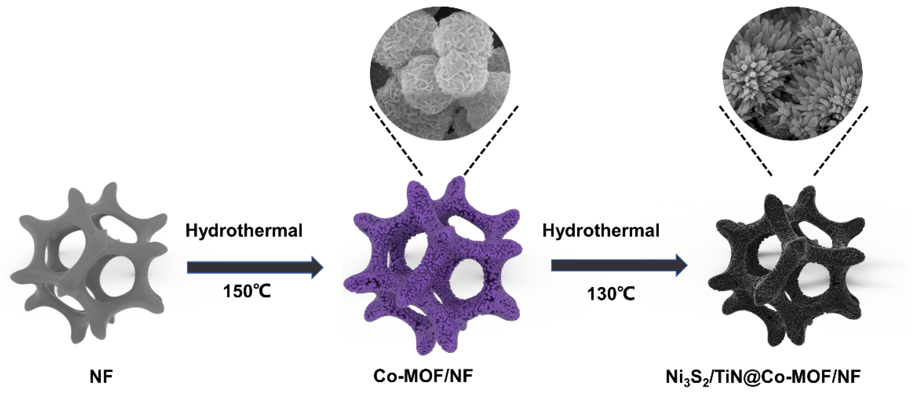
Scheme 1. A diagrammatic representation showing how the produced Ni3S2/TiN@Co-MOF/NF electrode was made.
Energies 17 02788 sch001
Figure 1. (a,b) XRD of Co-MOF and Ni3S2/TiN@Co-MOF/NF. (c) FTIR of Co-MOF/NF. (d,e) SEM of Co-MOF/NF. (f,g) SEM of Ni3S2/TiN@Co-MOF/NF. (h) EDS of Ni3S2/TiN@Co-MOF/NF. (i,j) TEM of Ni3S2/TiN@Co-MOF/NF. (k) HRTEM of Ni3S2/TiN@Co-MOF/NF.
Energies 17 02788 g001
Figure 2. XPS of Ni3S2/TiN@Co-MOF/NF. (a) Ni (b) S (c) N (d) Ti. Co-MOF/NF, Ni3S2/TiN@Co-MOF/NF (e) Nitrogen adsorption–desorption (f) porosity.
Energies 17 02788 g002
Figure 3. (a) CV for Co-MOF/NF, Ni3S2/TiN/NF, Ni3S2/Co-MOF/NF, and Ni3S2/TiN@Co-MOF/NF. (b) GCD for Co-MOF/NF, Ni3S2/TiN/NF, Ni3S2/Co-MOF/NF, and Ni3S2/TiN@Co-MOF/NF. (c) Specific capacitance retention in Co-MOF/NF, Ni3S2/TiN/NF, Ni3S2/Co-MOF/NF, and Ni3S2/TiN@Co-MOF/NF. (d) Nyquist curves for Ni3S2/TiN/NF, Ni3S2/Co-MOF/NF, and Ni3S2/TiN@Co-MOF/NF. (e) CV of Ni3S2/TiN@Co-MOF/NF with varying scan rates. (f) Relationship between Ni3S2/TiN@Co-MOF/NF’s peak current and scan rate. (g) GCD of Ni3S2/TiN@Co-MOF/NF with varying current densities. (h) Test of cyclic stability over 5000 turns, featuring power density of 8 A g−1. (i) Energyquist curve prior to and subsequent to cyclic stability test of 5000 turns.
Energies 17 02788 g003
Figure 4. (a) ASC schematic diagram. (b) CV of AC and Ni3S2/TiN@Co-MOF/NF. (c) CV at various ASC voltages. (d) CV for varied ASC scan rates. (e) GCD under varying current densities within ASC. (f) ASC of magnification performance. (g) ASC’s Ragone plan [66,67,68,69,70,71,72,73]. (h) ASC’s cyclic stability test. (i) Nyquist curve both prior to and after ASC’s cyclic stability test.
Energies 17 02788 g004
Disclaimer/Publisher’s Note: The statements, opinions and data contained in all publications are solely those of the individual author(s) and contributor(s) and not of MDPI and/or the editor(s). MDPI and/or the editor(s) disclaim responsibility for any injury to people or property resulting from any ideas, methods, instructions or products referred to in the content.