Abstract
A series of experiments were carried out to investigate the performance of a WEC rotor with platform motion. To achieve platform motion, a forced motion device with a rotor was installed in the Ocean Engineering Basin. In this study, the rotor’s performance was examined at various phase stages between incoming waves at three wave heights, and compared to a rotor without a PTO system. The phase stage where the rotor exhibited the largest pitch motion was identified, and the efficiencies of the rotor with the PTO system were analyzed during this stage. Without the PTO system, the rotor experienced its largest pitch motion when the rotating center was positioned at the zero-up crossing point of the incoming waves at three different wave heights. Furthermore, it was observed that in the optimal phase, the rotor’s efficiency increased with relatively large platform motion. These findings provide fundamental data for rotor design.
1. Introduction
Regarding environmental problems, renewable energy has become increasingly important. It is well known that renewable energy systems utilize wind, sunlight, ocean waves, etc. Among these, ocean wave energy, with its high density, is regarded as a promising environmental resource. A Wave Energy Converter (WEC) system is essential for harnessing this ocean energy. WEC systems can be classified into various types, with the oscillating water column type (OWC) and the floating body type being the most prevalent. In the case of the OWC type, oscillating water in a chamber pushes air, and a turbine in the OWC generates energy by rotating due to the air movement. Consequently, the OWC has maintenance advantages as it does not come into contact with seawater. Energy can be directly captured from wave-induced motions in the case of the floating body type. The energy absorption is relatively large near the resonance period of the floating body type. Additionally, the floating body type has a relatively simple shape, and manufacturing costs are low due to its relatively small size.
To design the floating body type of WEC, conventional design tools for ships and offshore structures can be utilized. Both frequency domain analysis and time domain analysis are widely employed in the design process. Frequency domain analysis is utilized to study hydrodynamic coefficients and the power extraction of vertical cylinders and spherical bodies for floating-body-type WECs [1,2,3]. Time domain analysis, using Cummins’s equation [4], allows for the evaluation of performance factors such as control mechanisms and the non-linearities of power take-off (PTO) systems. This method is extensively used in WEC system design. For instance, the performance of a heaving body with a PTO system, incorporating a high-pressure hydraulic circuit and a gas accumulator, was investigated [5]. A performance evaluation of Wavestar using time domain analysis was also conducted, with direct comparison to experimental results [6]. Additionally, time domain analysis and experimentation were conducted on a hemispherical floating body with varying slope angles [7]. In another study, time domain analysis was employed to design the submerged part of an axisymmetric floating body under irregular wave conditions, comparing hydrodynamic coefficients with changes in the submerged part’s shape [8]. Numerous researchers have utilized both frequency domain and time domain analyses in the design of floating-body-type WECs. Salter’s duck is a well-known floating-body-type WEC. It was first introduced in [9], and demonstrated 90% efficiency during the resonance period. The hydrodynamic performance of the Salter’s duck rotor was evaluated in [10] with varying geometric shapes. More recently, the WEPTOS WEC, developed by the Aalborg University Group, has gained attention. This WEC features an A-shaped floating body with multiple rotors inspired by Salter’s duck. Time domain analysis for the WEPTOS rotor was conducted in [11], and the results were directly compared to the experimental findings in [12]. Additionally, a modified WEC rotor inspired by Salter’s duck was designed in [13]. Computational Fluid Dynamics (CFD) analysis was employed in [14] to evaluate its performance, and attempts to increase power absorption by altering the metacentric height (GM) were explored in [15]. In [16], the power absorption of the WEPTOS rotor with two different configurations—2 and 4 WEPTOS—was evaluated with two different rotor widths. Recently, research has been conducted on a wind–wave hybrid system integrating multiple Salter’s ducks with FOWT platform pontoons [17].
In this study, experiments were conducted to assess the performance of a Salter-duck-type rotor under platform motion. A forced motion device was utilized to induce horizontal and vertical movements in order to simulate the platform motion. Additionally, various phases between incoming waves and the rotor were taken into account, as the waves approaching the rotors could vary in phase, particularly in the case of arrayed rotors. Three different wave heights were applied during the experiments to account for the non-linearity of rotor motion. Both no-load conditions and load conditions with a PTO system were tested.
2. Experimental Set-Up
2.1. Experimental Model
In this study, experiments were conducted to assess the performance of a Salter-duck-type rotor under platform motion. Figure 1 shows the experimental set-up, with model tests conducted at a 1/5.5 scale ratio in the Ocean Engineering Basin of the Korea Research Institute of Ships and Ocean Engineering (KRISO). During the experiment, a forced motion device was installed on the carriage rail within the Ocean Engineering Basin. Horizontal and vertical motion data were obtained from the platform motion data in [18]. The horizontal forced motion corresponded to the surge motion of the platform, while the vertical forced motion combined the heave and pitch motions of the platform. As shown in Figure 1c, the model tests incorporated a coulomb-damping-type power take-off (PTO) system installed on the forced motion device. Coulomb damping was achieved using a motor, with torque measured by a torque sensor. The rotor’s pitch motion was directly measured using a potentiometer connected to a timing belt. Table 1 summarizes the principal dimensions of the full-scale rotor, while Figure 2 shows the relative distance between the rotor and pontoon, along with the pontoon’s size. Pontoon locations and sizes were determined based on research from [18]. In this study, directional motions other than pitch motion were fixed during rotor motion.
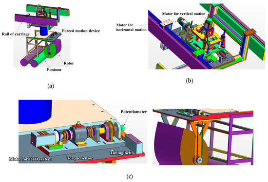
Figure 1.
Experimental set-up: (a) total system; (b) forced motion device; (c) system for PTO system and motion measurement.

Table 1.
Principal dimensions of the full-scale rotor.
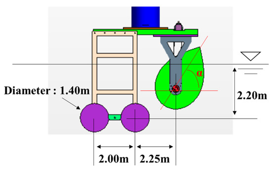
Figure 2.
Dimensions for model set-up.
2.2. Characteristics of Experimental Rotor Model
2.2.1. Without PTO Damping
The model tests without platform motion were conducted initially, followed by experiments with platform motion. Figure 3 shows the motion Response Amplitude Operators (RAOs) corresponding to different wave heights. The experimental data were directly compared with the results of the frequency domain analysis, which is denoted as AdFLOW and was developed as a potential-based program at KRISO. As shown in Figure 3, with an increase in wave height, the resonance periods of the rotor shift towards shorter wave periods, and the magnitudes of the motion RAOs decrease. This phenomenon occurs because the restoring moment of the rotor can vary based on the pitch angles of the rotor [19]. Consequently, conducting forced motion tests with increasing wave heights becomes necessary.
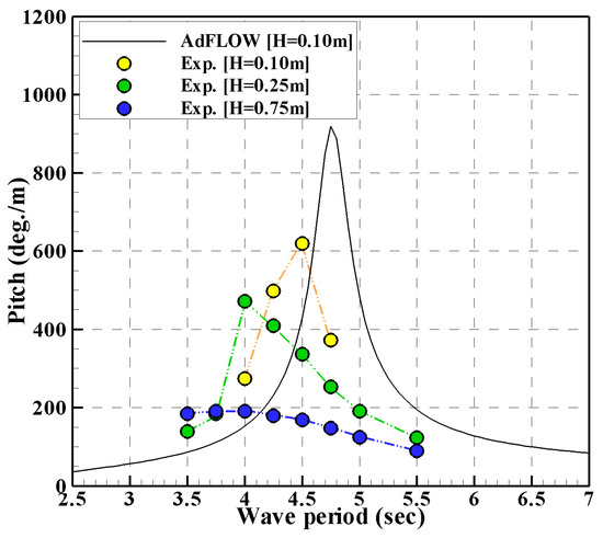
Figure 3.
Motion RAOs in relation to wave height.
2.2.2. With PTO Damping
Figure 4 shows the efficiencies of the rotor according to the PTO damping. As shown in Figure 3, the resonance period of the rotor under a wave height of 0.25 m aligns closely with a wave period of 4.00 s. It is widely recognized that the maximum efficiency of a WEC occurs during its resonance period. However, in the experiments, the highest efficiency of the rotor was observed at a different wave period near the resonance period, as shown in Figure 4. Therefore, forced motion tests with PTO damping were conducted at a wave period of 4.25 s.
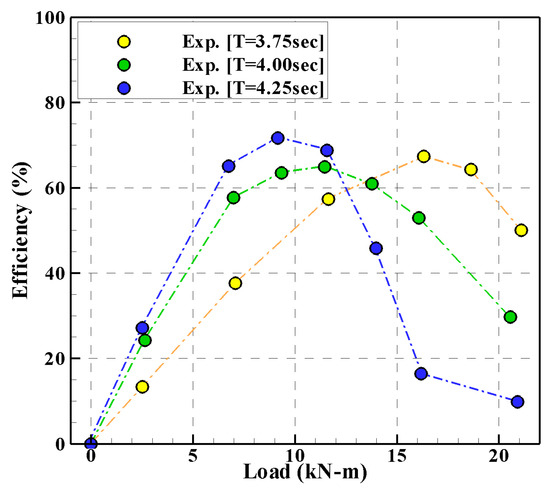
Figure 4.
Efficiency of the rotor in relation to PTO damping (H = 0.25 m).
2.3. Wave Conditions
Table 2 summarizes the wave conditions used in the experiments. For the wave conditions, a wave period of 4.75 s was selected to reflect the characteristic waves of Jeju Island, Republic of Korea [20]. The average wave height for Jeju Island is 0.75 m, but wave heights of 0.10 m and 0.25 m were chosen based on the linear wave theory. The experiments were conducted under these wave conditions without PTO damping. For experiments with PTO damping, a wave period of 4.25 s and a wave height of 0.25 m were selected for the tests conducted without platform motion. A wave height of 0.25 m was chosen to effectively evaluate the PTO damping effect in the forced motion tests. Model tests both without PTO damping and with PTO damping conditions were conducted with a wave heading of 180 degrees. Additionally, a coulomb damping type was utilized for the PTO damping.

Table 2.
Wave conditions.
2.4. Definition of Phase
To explain the phase difference between the rotor and the incoming waves, Figure 5 shows the WEPTOS WEC, equipped with 20 rotors. Each rotor can operate at different phases relative to one another, assuming the platform experiences surge motion exclusively, with no other directional movement. This phenomenon can also occur in the vertical motion of the platform. Hence, to investigate the performance characteristics of the rotor at different phases, forced motion tests were conducted across various phases. To manipulate the phases, the starting times of the forced motion device were adjusted, ensuring consistency within the same wave conditions. Furthermore, the durations of movement in both the horizontal and vertical directions of the forced motion device were assumed to match the wave period of the incoming waves.

Figure 5.
WEPTOS WEC [16].
Figure 6 defines the phases concerning the starting time of the forced motion device. During the model tests, the wave periods of the incoming waves were divided into eight equal parts. For instance, during the Phase 4 stage, the forced motion device commenced when the rotating center of the rotor was positioned at the zero-up crossing point of the incoming wave.

Figure 6.
Definition of the phases (T = 4.75 s, H = 0.75 m).
2.5. Forced Motion Conditions
To determine the magnitudes of the horizontal and vertical motions of the forced motion device, motion tests were conducted on the moored platform using a soft mooring system and regular waves with varying wave periods and wave heights.
As shown in Figure 7, it is evident that the platform motions exhibit linearity across the three different wave heights. Particularly noteworthy is the observation that platform motions are relatively minimal within wave periods ranging from 4.25 s to 4.75 s.
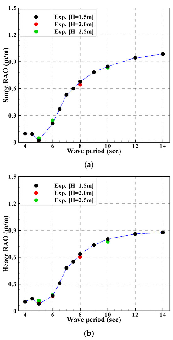

Figure 7.
Motion RAOs of the platform: (a) surge RAOs; (b) heave RAOs; (c) pitch RAOs.
Figure 8 shows the time–history graphs of the surge, heave, and pitch motions of the platform during a wave period of 4.50 s. As shown in Figure 8a, the surge motion of the platform exhibits periodic motion due to the incoming wave, along with longer periodic motion caused by the mooring lines. Similarly, Figure 8b shows the periodic motions of the platform’s heave and pitch motions induced by the incoming wave. In this study, the magnitude of the horizontal motion of the forced motion device was determined based on the surge Response Amplitude Operator (RAO), considering the wave heights of the incoming waves. Additionally, the magnitude of the vertical motion was initially determined based on the heave and pitch RAOs, taking into account the wave heights of the incoming waves and the phase difference between the heave and pitch motions. Furthermore, to obtain the vertical motion of the forced motion device, the obtained vertical motion was converted to the vertical motion of the rotor.

Figure 8.
Time–history graphs for the surge, heave, and pitch motions of the platform in the wave period of 4.50 s: (a) time–history graph for surge motion; (b) time–history graph for heave and pitch motions.
Table 3 summarizes the horizontal and vertical motions of the forced motion device. In the case of the test without PTO damping, the horizontal motion of the forced motion device is relatively small compared to the horizontal motion of the forced motion device with PTO damping. Additionally, the trend of the vertical motion of the forced motion device is opposite to the trend of the horizontal motion of the forced motion device.

Table 3.
Horizontal and vertical motions of the forced motion device.
3. Experimental Results
3.1. Without PTO Damping
In this study, experiments were conducted to investigate the pitch motions of the rotor under conditions without PTO damping. Figure 9 shows representative snapshots of the experiments under both the fixed and forced motion conditions of the forced motion device, with a wave height of 0.75 m. It can be observed that there are slight differences in the pitch motions of the rotor between the fixed and forced motion conditions of the forced motion device. Thus, the platform motion can influence the pitch motion of the rotor even in small motion regions, as shown in Figure 7.

Figure 9.
Representative snapshots for the experiments in the conditions of fixed motion and forced motion of the forced motion device (H = 0.75 m): (a) fixed motion test; (b) forced motion test (Phase 4 stage) [21].
Figure 10 shows the results of the fixed motion tests with increasing wave heights. The pitch motions of the rotor and the wave heights of the incoming waves were normalized by the respective wave heights, and the time–history results were also normalized by the wave period of 4.75 s. As shown in Figure 7, it is evident that the normalized pitch motions of the rotor decrease as the wave heights increase. Additionally, the pitch motions of the rotor are in phase with the incoming waves as a function of wave height.

Figure 10.
Results from the fixed motion tests on the forced motion device: (a) H = 0.10 m; (b) H = 0.25 m; (c) H = 0.75 m.
Figure 11, Figure 12 and Figure 13 show the time–history graphs for the results of the forced motion tests in Phases 1, 4, and 7. It is apparent that the phases between the incoming waves and the motions of the forced motion device vary according to the phase stages. Additionally, the pitch motions of the rotor decrease with increasing wave heights. In the case of a wave height of 0.10 m, the pitch motions of the rotor in the forced motion tests were relatively small compared to the pitch motion of the rotor in the fixed motion tests. However, in the Phase 4 stage under relatively high wave heights, the pitch motions of the rotor are slightly larger than those in the fixed motion tests. Furthermore, for the three different wave heights, the pitch motions of the rotor in the Phase 7 stage are relatively small compared to the results in other conditions. Therefore, it can be observed that the pitch motions of the rotor change according to the phase stages, and the variations in the pitch motions of the rotor in accordance with the phase stages for the three different wave heights differ from each other.
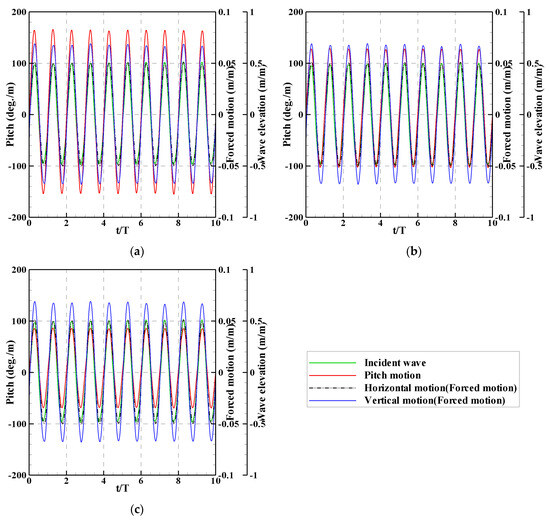
Figure 11.
Results from the forced motion tests in Phase 1 stage: (a) H = 0.10 m; (b) H = 0.25 m; (c) H = 0.75 m.
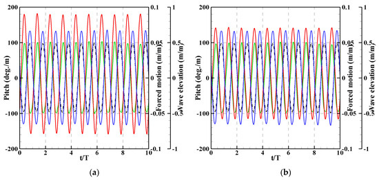

Figure 12.
Results from the forced motion tests in Phase 4 stage: (a) H = 0.10 m; (b) H = 0.25 m; (c) H = 0.75 m.

Figure 13.
Results from the forced motion tests in Phase 7 stage: (a) H = 0.10 m; (b) H = 0.25 m; (c) H = 0.75 m.
Figure 14 shows the ratios of the amplitudes and magnitudes of the pitch motions. The ratio for the pitch motion was defined as the relation between the pitch motions in the fixed motion and forced motion tests, with the ratios of the pitch motions in the fixed motion tests set to 1. Additionally, the results in Figure 14 represent the average values for 10 periods. As shown in Figure 14a, all positive and negative amplitudes of the pitch motions in the forced motion tests are relatively small compared to the results in the fixed motion tests. Notably, only in the forced motion test cases, the positive and negative amplitudes of the pitch motions in the Phase 4 stage are relatively large compared to the results in the other phase stages. Therefore, the pitch motion of the rotor can increase when the zero-up crossing of the incoming wave is located at the rotating center of the rotor during forced motion tests. Furthermore, the positive and negative amplitudes of the rotor increase from the Phase 1 stage to the Phase 4 stage and decrease again from the Phase 5 stage to the Phase 8 stage. As shown in Figure 14b,c, the trends of the positive and negative amplitudes of the rotor at the wave heights of 0.25 m and 0.75 m exhibit similar trends as at the wave height of 0.10 m. Additionally, under a wave height of 0.25 m, the positive amplitude of the rotor in the Phase 4 stage is relatively large compared to the fixed motion tests, whereas the negative amplitude in the forced motion tests is relatively small. In the forced motion tests under a wave height of 0.75 m, both the positive and negative amplitudes of the rotor increase, indicating that the amplitudes of the rotor in the forced motion tests can increase with increasing wave heights. Furthermore, as shown in Figure 14d, the magnitudes of the rotor pitch motions increase with increasing wave heights, with the magnitudes of the rotor pitch motions in the forced motion tests under a wave height of 0.75 m being relatively large compared to those in the fixed motion tests. Additionally, in the forced motion tests, the magnitude of the rotor pitch motion in the Phase 4 stage is the largest among the results. Depending on the wave height, different increases and decreases in the pitch amplitudes of the rotor for each wave condition can occur due to changes in the added mass or GM in the pitch direction caused by the platform motion.
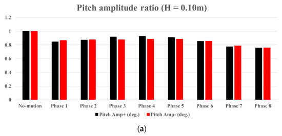

Figure 14.
Comparisons for the ratios of the amplitudes and magnitudes of the pitch motions: (a) ratio of the pitch amplitudes (H = 0.10 m); (b) ratio of the pitch amplitudes (H = 0.25 m); (c) ratio of the pitch amplitudes (H = 0.75 m); (d) ratio of the pitch magnitudes.
Table 4 summarizes the relative variances in the pitch motions of the rotor in the forced motion tests compared to the results of the fixed motion tests. In the Phase 4 stage, the pitch motions of the rotor with platform motion are relatively large compared to the pitch motions of the rotor in the other phase stages. Additionally, the pitch motions of the rotor with platform motion increase with increasing wave height. At the wave height of 0.75 m, the increase in the pitch motion of the rotor with platform motion is about 7%. Specifically, the increases in the positive and negative amplitudes of the rotor are about 9% and 5%, respectively.

Table 4.
Relative variances in the pitch motions of the rotor in the forced motion tests (yellow: <90%; green: 90% ≤ 100%; red: 100%<).
3.2. With PTO Damping
In this study, experiments were conducted in the Phase 4 stage with the PTO damping condition using a wave period of 4.25 s and a wave height of 0.25 m. The optimal PTO damping, approximately 9 kN-m, was determined for the incoming wave condition, as shown in Figure 6. Figure 15 shows representative snapshots of the experiments with PTO damping (9 kN-m). It is evident that the maximum negative amplitude of the rotor in the fixed motion test is relatively large compared to the maximum negative amplitude of the rotor in the forced motion test. Therefore, the absorbed power can be influenced by the platform motion.
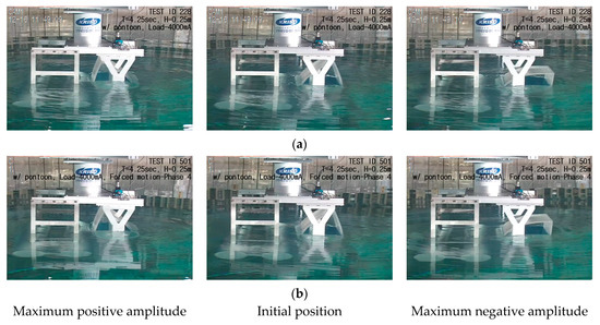
Figure 15.
Representative snapshots of the experiments in the conditions of fixed motion and forced motion of the forced motion device with PTO damping (9 kN-m): (a) fixed motion test; (b) forced motion test (Phase 4 stage).
Figure 16 shows the time–history graphs for the experimental results, including the Phase 4 stage in the forced motion test. As shown in Figure 16a,b, the phase between the pitch motion of the rotor and the incoming wave slightly changes due to the PTO damping. Additionally, the pitch motion of the rotor significantly decreases due to the PTO damping, with a further slight decrease caused by the platform motion. Furthermore, as shown in Figure 16b,c, the phase between the pitch motion of the rotor and the incoming wave is minimally affected by the platform motion. Therefore, the platform motion only affects the magnitude of the pitch motion of the rotor.
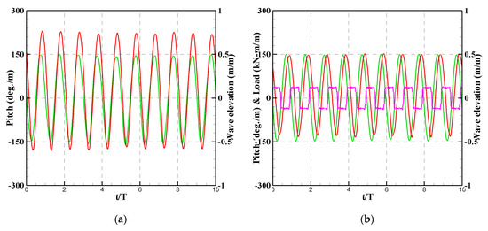

Figure 16.
Time–history graphs for the experimental results: (a) without PTO damping; (b) fixed motion test; (c) forced motion test in Phase 4 stage.
The experimental results from the fixed motion test and the forced motion test, which are averaged over 10 periods, are shown in Figure 17. As mentioned earlier, the pitch motion of the rotor in the forced motion test decreases compared to the pitch motion of the rotor in the fixed motion test due to the platform motion. Consequently, the pitch velocity of the rotor in the forced motion test is relatively small compared to the fixed motion test. Furthermore, under the same PTO damping, the efficiency of the rotor with the platform motion decreases by about 7% compared to the efficiency of the rotor without the platform motion. The platform motion can alter the added moment or GM of the rotor, potentially leading to changes in the optimal PTO damping. Therefore, the performance of the rotor is influenced by the platform motion, highlighting the importance of evaluating rotor performance with platform motion during the design phase.
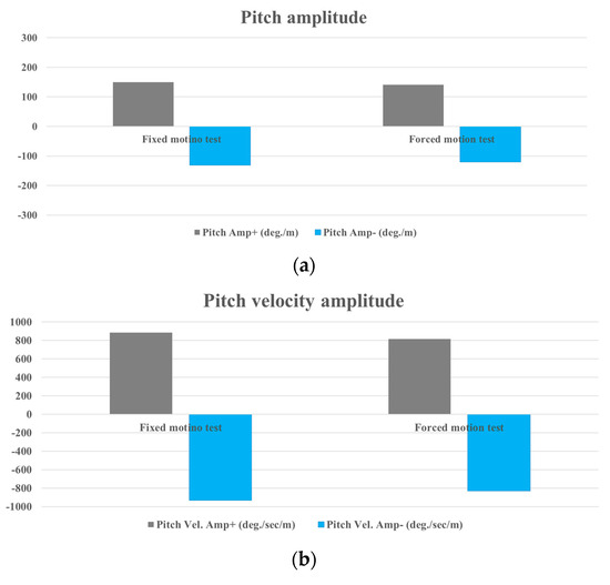
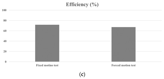
Figure 17.
Comparison of results from the fixed motion test and forced motion test in Phase 4 stage: (a) pitch amplitude; (b) pitch velocity amplitude; (c) rotor efficiency.
3.3. Additional Experiment on Large Motion of Platform
In this study, additional experiments were conducted in the Phase 4 stage to investigate the changes in the rotor’s performance under large platform motion. The maximum amplitudes of the forced motion device in the horizontal and vertical directions were 0.1 m each. Therefore, the experiments were conducted at both the maximum amplitudes and half of the maximum amplitudes of the forced motion device. Figure 18 shows representative snapshots of the experiments conducted without the PTO system. It is observed that significant slamming phenomena occur, and the rotating angles of the rotor do not differ significantly from those in Figure 9b. Due to the buoyancy of the rotor in the positive and negative directions, the increase in the rotating angle of the rotor during large motion of the platform may be limited. As shown in Figure 19, the magnitudes of the pitch motions of the rotor at half of the maximum amplitude and the maximum amplitude of the forced motion device are similar, despite significant differences in the magnitudes of platform motion. Additionally, these magnitudes are similar to the magnitude of the pitch motion of the rotor in Figure 12c.

Figure 18.
Representative snapshots of the experiments without the PTO system under the condition of the forced motion of the forced motion device (T = 4.75 s, H = 0.75 m, Phase 4 stage): (a) half of the maximum amplitude of the forced motion device; (b) maximum amplitude of the forced motion device.

Figure 19.
Results from the forced motion tests with large motion of the platform in Phase 4 stage: (a) half of the maximum amplitude of the forced motion device; (b) maximum amplitude of the forced motion device.
The magnitudes of the pitch motions in each wave height condition are summarized in Figure 20. Here, the normalized positive and negative amplitudes of the rotor by wave height are presented according to the normalized vertical motion of the platform by wave height. In the case of the wave height of 0.10 m, the pitch motion of the rotor decreases when the platform motion occurs, while the pitch motions of the rotor slightly increase when the platform motion occurs in the case of the other wave height conditions. As mentioned previously, the trends of the pitch motions of the rotor in each wave height condition can vary due to changes in the added moment or GM caused by the platform motion. Therefore, in order to investigate these physical phenomena, it is necessary to conduct numerical studies using a CFD tool. In the results for the wave height of 0.75 m, due to the limitations of the positive and negative amplitudes of the rotor due to buoyancy, it is observed that the trend of the pitch motion of the rotor appears to converge with increasing vertical motions of the platform.
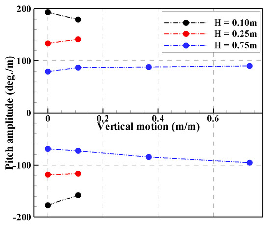
Figure 20.
Comparison of the pitch amplitude of the rotor with platform motion in Phase 4 stage.
Figure 21 shows representative snapshots of the experiments with the PTO system under the forced motion condition of the forced motion device in the Phase 4 stage. The pitch motions of the rotor during large platform motions are relatively large compared to those in Figure 15b. The significant pitch motion of the rotor can be attributed to the inertia of the rotor, even when the PTO damping acts on the rotor at relatively small wave heights. As shown in Figure 17c, the rotor efficiency may decrease during small platform motions, while it may increase as larger platform motions occur. Additionally, as shown in Figure 22, the pitch motions of the rotor significantly increase due to large platform motions compared to the pitch motions of the rotor in Figure 16c. However, the pitch motion of the rotor at the maximum amplitude of the forced motion device only slightly increases compared to the pitch motion of the rotor at half of the maximum amplitude of the forced motion device. This is because the positive and negative amplitudes of the rotor approach the limitation of the rotating angle imposed by the buoyancy of the rotor at the maximum amplitude of the forced motion device.
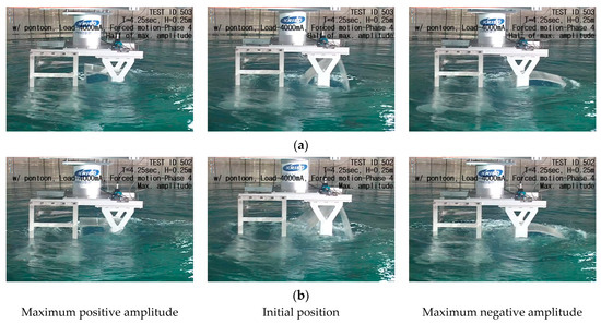
Figure 21.
Representative snapshots of the experiments with the PTO system under the condition of the forced motion of the forced motion device (T = 4.25 s, H = 0.25 m, Phase 4 stage): (a) half of the maximum amplitude of the forced motion device; (b) maximum amplitude of the forced motion device.

Figure 22.
Results from the forced motion tests with large motions of the platform in the Phase 4 stage: (a) half of the maximum amplitude of the forced motion device; (b) maximum amplitude of the forced motion device.
The performance of the rotor corresponding to the magnitude of platform motion is summarized in Figure 23. As shown in Figure 23a, the pitch motion of the rotor decreases during the smallest motion of the platform, compared to the pitch motion of the rotor in the fixed platform condition. This reduction is attributed to changes in the added moment or GM of the rotor due to the platform motion. However, the pitch motion of the rotor significantly increases at half of the maximum amplitude of the forced motion device due to the rotor’s inertia when the platform is moved. In the case of the largest platform motion, the pitch motion of the rotor increases slightly compared to the pitch motion of the rotor at half of the maximum amplitude of the platform, owing to the buoyancy of the rotor. Additionally, the trend of pitch velocity mirrors that of pitch motion, as shown in Figure 23b.
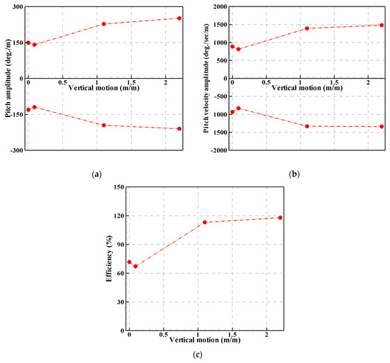
Figure 23.
Comparison of the performance of the rotor in accordance with the platform motion in the Phase 4 stage: (a) pitch amplitude; (b) pitch velocity amplitude; (c) rotor efficiency.
In this study, the same PTO damping was applied to the rotor for each condition, so the efficiency of the rotor increased when the pitch velocity of the rotor increased. As shown in Figure 23c, the efficiency of the rotor decreased by about 7% with the smallest motion of the platform compared to the efficiency of the rotor in the fixed platform condition. However, under the same PTO damping, the efficiency of the rotor increased by about 48% with half of the maximum amplitude of the forced motion device compared to the efficiency with the smallest motion of the platform. Additionally, the efficiency of the rotor increased by about 4% at the maximum amplitude of the forced motion device compared to the efficiency at half of the maximum amplitude of the forced motion device. Nevertheless, it is important to note that the optimal PTO damping may change due to variations in the added moment or GM of the rotor when the platform experiences significant movement. Moreover, increasing the motion of the platform could potentially enhance the absorbed power of the rotor.
4. Conclusions
An experiment was conducted to investigate the performance of a WEC rotor. From a series of experiments, the following conclusions are drawn:
- (1)
- In the absence of a PTO system, the largest pitch motion of the rotor with platform motion occurred during the Phase 4 stage across all wave heights. However, with the smallest wave height, the pitch motion of the rotor with platform motion was relatively small compared to that of the rotor without platform motion, while for other wave heights, the pitch motions of the rotor with platform motion increased compared to those without platform motion. The resulting variation in pitch motions could be attributed to changes in the added moment or GM of the rotor across different wave heights. This finding is consistent with [21].
- (2)
- In relation to the pitch motion of the rotor under significant platform motion, the trend of the rotor’s pitch motion at the wave height of 0.75 m seems to converge with increasing vertical motions of the platform. This convergence may be attributed to the limitation of the rotor’s rotating angle in both positive and negative directions, imposed by its buoyancy.
- (3)
- In the presence of a PTO system, the efficiency of the rotor decreased with platform motion compared to the experiments without platform motion. The movement of the platform could alter the magnitude of the rotor’s pitch motion due to variations in the added moment or GM of the rotor. Consequently, the optimal PTO damping for a moving platform may differ from that for a stationary platform.
- (4)
- In the case of significant platform motion, the rotor’s efficiency increased due to the rotor’s inertia. Therefore, increasing the platform’s motion could be a viable method to enhance the absorbed power of the rotor during the design phase of a WEC rotor. Particularly, for the maximum platform motion, the rotor’s efficiency showed a slight increase compared to that at half the maximum platform motion.
In the future, additional research is planned to conduct model tests incorporating actual platforms and multiple rotors with applied PTO systems, referencing this study. The research will aim to scrutinize the effects of phase difference and platform motion more closely.
Author Contributions
Investigation, writing—original draft preparation, Y.-J.H.; investigation, formal analysis, C.-H.L.; supervision, S.-H.S.; investigation, writing—review and editing, J.-Y.P. All authors have read and agreed to the published version of the manuscript.
Funding
This research was supported by the Korea Research Institute of Ships and Ocean Engineering, a grant from the Endowment Project “Development of Smart Sensor Technology for Underwater Environment Monitoring” funded by the Ministry of Oceans and Fisheries (PES5192).
Data Availability Statement
The original contributions presented in the study are included in the article, further inquiries can be directed to the corresponding author.
Conflicts of Interest
The authors declare no conflicts of interest.
References
- Yeung, R.W. Added Mass and Damping of a Vertical Cylinder in Finite-depth Waters. Appl. Ocean Res. 1981, 3, 119–133. [Google Scholar] [CrossRef]
- Evans, D.V.; Mciver, P. Added Mass and Damping of a Sphere Section in Heave. Appl. Ocean Res. 1984, 6, 45–53. [Google Scholar] [CrossRef]
- Budal, K.; Falnes, J. Wave Power Conversion by Point Absorbers: A Norwegian Project. Int. J. Ambient Energy 1982, 3, 59–67. [Google Scholar] [CrossRef]
- Cummins, W.E. The Impulse Response Function and Ship Motions. Schiffstechnik 1962, 47, 101–109. [Google Scholar]
- Falcão, A.F.O. Modelling and Control of Oscillating-body Wave Energy Converters with Hydraulic Power Take-off and Gas Accumulator. Ocean Eng. 2007, 34, 2021–2032. [Google Scholar] [CrossRef]
- Zurkinden, A.S.; Ferri, F.; Beatty, S.; Kofoed, J.P.; Kramer, M.M. Non-linear Numerical Modeling and Experimental Testing of a Point Absorber Wave Energy Converter. Ocean Eng. 2014, 78, 11–21. [Google Scholar] [CrossRef]
- Do, H.T.; Dinh, Q.T.; Nguyen, M.T.; Phan, C.B.; Dang, T.D.; Lee, S.; Park, H.G.; Ahn, K.K. Effects of Non-vertical Linear Motions of a Hemispherical-float Wave Energy Converter. Ocean Eng. 2015, 109, 430–438. [Google Scholar] [CrossRef]
- Gao, H.; Liang, R. Performance Analysis of Axisymmetric Floating Energy Harvesters and Influences of Parameters and Shape Variation. Int. J. Energy Res. 2018, 43, 2057–2074. [Google Scholar] [CrossRef]
- Salter, S.H. Wave Power. Nature 1974, 249, 720–724. [Google Scholar] [CrossRef]
- Mynett, A.E.; Serman, D.D.; Mei, C.C. Characteristics of Salter’s Cam for Extracting Energy from Ocean Waves. Appl. Ocean Res. 1979, 1, 13–20. [Google Scholar] [CrossRef]
- Rapuc, S. Numerical Study of the WEPTOS Single Rotor. Master Thesis, Aalborg University, Aalborg, Denmark, 2012. [Google Scholar]
- Pecher, A.; Kofoed, J.P.; Marchalot, T. Experimental Study on a Rotor for WEPTOS; Aalborg University DCE Contract Report No. 110; Aalborg University: Aalborg, Denmark, 2011. [Google Scholar]
- Poguluri, S.K.; Bae, Y.H. A Study on Performance Assessment of WEC Rotor in the Jeju Western Waters. Ocean Syst. Eng. 2018, 8, 361–380. [Google Scholar]
- Ko, H.S.; Kim, D.E.; Cho, I.H.; Bae, Y.H. Numerical and Experimental Study for Nonlinear Dynamic Behavior of an Asymmetric Wave Energy Converter. In Proceedings of the International Society of Offshore and Polar Engineering, Honolulu, HI, USA, 16–21 June 2019. [Google Scholar]
- Ha, Y.J.; Park, J.Y.; Shin, S.H.; Bae, Y.H. Evaluation of Generating Power in Low Wave Height for Asymmetric Rotor using Frequency Domain Analysis. J. Korean Soc. Mar. Environ. Energy 2019, 22, 253–261. [Google Scholar] [CrossRef]
- Margheritini, L.; Kofoed, J.P. WEPTOS Wave Energy Converters to Cover the Energy Needs of a Small Island. Energies 2019, 12, 423. [Google Scholar] [CrossRef]
- Yazdi, H.; Ghafari, H.R.; Ghassemi, H.; He, G.; Karimirad, M. Wave Power Extraction by Multi-Salter’s Duck WECs Arrayed on the Floating Offshore Wind Turbine Platform. Energy 2023, 278, 127930. [Google Scholar] [CrossRef]
- Park, J.Y.; Nam, B.W.; Shin, S.H.; Park, I.B.; Won, Y.U.; Oh, Y.J.; Roh, C.; Cho, S.J. An Experimental Study on the Wave Response of Arrayed-buoy Wave Energy Converter Changing Platform Included Angle. In Proceedings of the Autumn Meetings of Korean Society for Marine Environmental and Energy, Yeosu, Republic of Korea, 22 November 2018. [Google Scholar]
- Ha, Y.J.; Park, J.Y.; SHIN, S.H. Numerical Study on Non-linear Dynamic Behavior of an Asymmetric Rotor for Wave Energy Converter in Regular Waves. Processes 2021, 9, 1477. [Google Scholar] [CrossRef]
- Hong, K.Y.; Ryu, H.J.; Shin, S.H.; Hong, S.W. Wave Energy Distribution at Jeju Sea and Investigation of Optimal Sites for Wave Power Generation. J. Ocean Eng. Technol. 2004, 18, 8–15. [Google Scholar]
- Ha, Y.J.; Park, J.Y.; Rho, C.; Shin, S.H. An Experimental Study for the Non-linear Motion Characteristics of an Asymmetric Rotor by Pontoons. J. Korean Soc. Mar. Environ. Energy 2020, 23, 192–202. [Google Scholar] [CrossRef]
Disclaimer/Publisher’s Note: The statements, opinions and data contained in all publications are solely those of the individual author(s) and contributor(s) and not of MDPI and/or the editor(s). MDPI and/or the editor(s) disclaim responsibility for any injury to people or property resulting from any ideas, methods, instructions or products referred to in the content. |
© 2024 by the authors. Licensee MDPI, Basel, Switzerland. This article is an open access article distributed under the terms and conditions of the Creative Commons Attribution (CC BY) license (https://creativecommons.org/licenses/by/4.0/).