1. Introduction
Wireless power transfer (WPT) technology provides an alternative method of energy transmission without cords and the corresponding limitations [
1,
2,
3,
4]. The technology provides high convenience and increased safety, which makes it beneficial for further integration in automotive and consumer electronics. However, to integrate the technology, we need a comprehensive analysis of such systems in terms of efficiency, safety, integration cost, etc. Understanding the challenges and limitations will lead to the possibility of extracting the full potential of this energy delivery technology.
The variety of utilization is wide. Such technologies can also be used in medical applications [
5,
6]. WPT proposes revolutionary methods of medical implant integration and utilization. One of them is pacemaker charging, where the pacemaker can be recharged in a non-invasive way without any damage to the human body. Another application is wheelchair charging, which makes it more convenient for people with physical limitations to use such equipment without the necessity to connect a wheechair via wired connection for battery recharging.
The widespread integration of WPT technology requires careful consideration of various aspects and tradeoffs [
7,
8,
9,
10,
11,
12]. The first concern comes from the nature of WPT technology, which implies a gap between the receiver and the transmitter (usually the air gap) [
13]. This distance causes losses in efficiency, and with an increase in the distance, the efficiency continues to fall [
14,
15]. Additionally, any objects situated near the power transmission path can also influence the efficiency. In addition to efficiency degradation, depending on the material, these objects can be heated by the transmitted energy (caused by eddy currents in metal, etc.). In this case, additional foreign object detection units should be integrated in order to not damage the energy transmission system and omit any dangerous results.
Another concern is exposure to the electromagnetic field, which can influence humans or animals. As scooters operate at comparably low power ratings (hundreds of watts) and with a relatively small distance between the primary and the secondary side, the influence of the electromagnetic field is relatively small.
Nevertheless, in a very general case, the influence of the human body should be carefully analyzed in the case of a human body with medical implants [
16,
17,
18]. To decrease the effects of the electromagnetic field on the human body and implanted medical devices, additional passive or active methods of shielding are applied. In simple solutions, additional metal shields or pot cores are used to concentrate the field and to omit leakage of the field, and they are strongly concentrated between the transmitter and the receiver coils.
Another point is providing compatibility with existing wired and non-wired infrastructure in terms of various standards, which makes widespread adoption of the technology challenging. The standards of wireless energy transmission [
19,
20,
21,
22] and interoperability must be comprehensively analyzed in order to be deployed in everyday usage. Also, for a particular group of applications, there are ranges and frequency groups that are standardized. The operating frequency for the wireless charging of light-duty electric vehicles is 81–90.00 kHz, which is regulated by the Society of Automotive Engineers (SAE) Task Force’s J2954 standard. It is recommended to set it to 85 kHz for electric vehicle (EV) applications [
9].
Despite these limitations, the technology of wireless charging is becoming more popular. With the development of new materials, some of the limitations have disappeared (like inverter operation frequency limitations caused by metal shields composed of metal plates instead of the currently used ferromagnetic materials), which has opened up new possibilities for research in the last few decades.
In the conditions of increased urbanization, today’s research into the application fields has proposed optimistic outcomes in terms of investments covering the wireless charging of small-scale vehicles like scooters, electric bicycles, etc.
A common diagram of such an infrastructure is shown in
Figure 1. The transmitter (blue color) rectifies the grid voltage via utilization of a high-frequency inverter, and the transmitter delivers energy to the receiver coil. This high-frequency energy is rectified to charge the battery of the vehicle.
The technology of WPT is well established and has been tested for high-power applications [
23,
24,
25,
26], but the economic aspect is a bottleneck for mass implementation and should be taken into careful consideration. One of the main points is the costs related to WPT infrastructure development.
The purpose of this paper is to analyze the possibility of integrating WPT technology into scooters based on the case study analysis. Our focus is on the optimal design and the limitations of inductive coupling technology as well as on the possible solutions that can be applied to make the technology of WPT viable and competitive against conventional wired charging solutions.
2. Topology and Selection of the Compensation Method
To select a proper converter topology along with the compensation circuit, we need the scooter parameters. For this purpose, solutions of scooters available on the current (2024) market were analyzed statistically to evaluate the preferred parameters of the solution that would be competitive in the near future and can be used as an object of wireless power transfer technology integration. In our analysis, we used a freely available dataset “
https://freshlycharged.com/” (accessed on 20 May 2024) of available solutions, which contains more than 500 solutions operating in various domains.
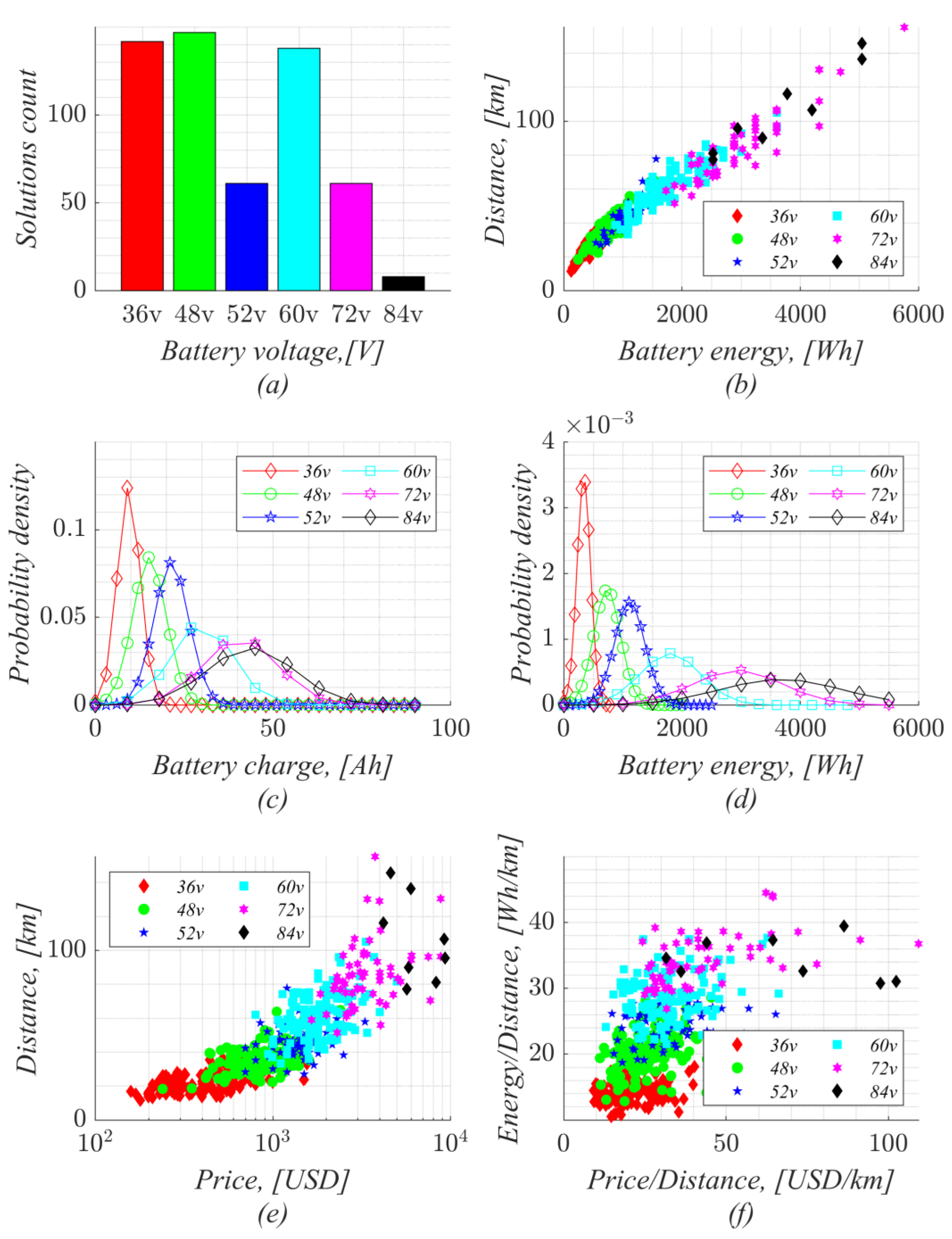
Figure 2a shows the number of solutions for the main operating voltages of the batteries (a few solutions with an operating voltage differing from those listed are not shown, as only one to three solutions of a particular voltage are available currently). As can be seen, the main interest (in terms of the number of available solutions) is in the solutions at the operating voltages of 36, 48, and 60 V.
The outdoor usage of the vehicles and limited space for battery integration provides a list of constraints. The first constraint is the operating voltage. Outdoor operation makes it impossible to perform any operation at a high voltage rating due to safety constraints, which is a concern in places with high humidity and mechanical interactions.
The second limitation is the size of the battery. In order to be competitive in terms of convenience, the tradeoff between the battery capacity (and corresponding size) and the distance that can be covered by one battery charge should be found (
Figure 2b). Under these considerations, available solutions can be divided into two domains: compact solutions with middle traveling distance capacity and bulky solutions with high traveling distance capacity. Solutions in the first domain are convenient for use in a city where the demand on the travel distance capacity is mostly covered by 20–40 km on one charge. These solutions are mostly covered by operating voltages of 36 and 48 V. Solutions in the second domain are convenient for use on terrain where the vehicles can be equipped with big wheels and have a travel distance demand of at least 30 km. These solutions need operating voltages of 60 and 72 V.
The statements above can be further verified by the analysis of battery charge (
Figure 2c) and battery capacity (
Figure 2d). For this purpose, the probability density was built for this parameter for each of the main battery operating voltages. It can be seen that low-voltage solutions are equipped with batteries of low capacity (a few hundred Wh), while high-voltage solutions (related to the distribution of current solutions) are equipped with battery capacities of up to thousands of Wh.
It should also be pointed out that with the increase in distance and operating voltage, the price of the scooter drastically increases (
Figure 2e). For better representation of this steep relationship, the scale for the price was chosen to be logarithmic. As can be seen, the price of the scooter can reach nearly USD 10,000.
For clarity, in the analysis of the scooter design in terms of cost, the price of the scooter per distance and energy per distance was determined (
Figure 2f). The x axis denotes the amount of money from the price of the scooter spent to obtain 1 km of travel distance. This criterion shows the level of optimization achieved to make a cheap solution with a long travel distance.
On the other hand, as the battery energy is proportional to the price of a charged battery with a constant tariff, there is a possibility to use the scooter energy and the maximum travel distance to estimate how efficiently the energy (and, correspondingly, the money during each charge) is used. The only omission in this analysis is related to the lack of information about the scooter charging stations. Thus, the efficiency of the charging station attached to each scooter was chosen to be the same.
The scatter plot of all solutions shows that the most optimized scooter designs in terms of scooter price per kilometer operate with voltages of 36 and 48 V, while the worst scooter optimization in terms of this criterion are scooters at the operating voltages of 72 and 84 V. The best solution in terms of energy (charging cost) per distance is at the operating voltage of 36 V.
Unfortunately, the dataset lacks information about the battery type and corresponding charging operation parameters (charging type, charging power). A few solutions were further investigated in terms of battery type and other related parameters.
Table 1 shows the summary of the parameters of the popular wireless scooter charging solutions currently available on the market. As can be seen, in the popular solutions in the range of 36–48 V, the charging power varies from 50 to 100 W (average 90 W). The charging time varies in the range of 5–10 h, with an average of 7.5 h.
Considering these aspects, the results of the available commercial and non-commercial solutions and scooter charging stations in cities as the main interest for a wireless power transfer technology indicate that the battery voltage range for most scooters varies in the range of 36–48 V. Regarding the constraints concerning a decrease in the battery lifetime related to charging at high power ratings, the maximum charging power should not exceed 500 W. As 36 V batteries are commonly charged at ratings of hundreds of W and any increase in the charging power can cause battery lifetime decrease concerns, it can be stated that the delivery of 100 W of wireless power transfer energy seems to be a reasonable tradeoff. It covers most of the existing low-power scooters while keeping the charging speed comparably equivalent to conventional contact charging.
WPT technology, particularly inductive coupling technology, utilizes a high diversity of inverter topologies and types of compensation to satisfy the chosen application requirements.
To increase the power transfer capabilities of inductive coupling technology and the overall system efficiency, the coupled coils are compensated by the reactive elements or a combination (usually single capacitors). These capacitors are tuned to work at resonance with the coupled coils at the inverter switching frequency. Compensation capacitors can be connected in series or in parallel with each of the coupled coils. For the case of a single transmitter and a single receiver, there are four solutions: SS (series–series), SP (series–parallel), PS (parallel–series), and PP (parallel–parallel).
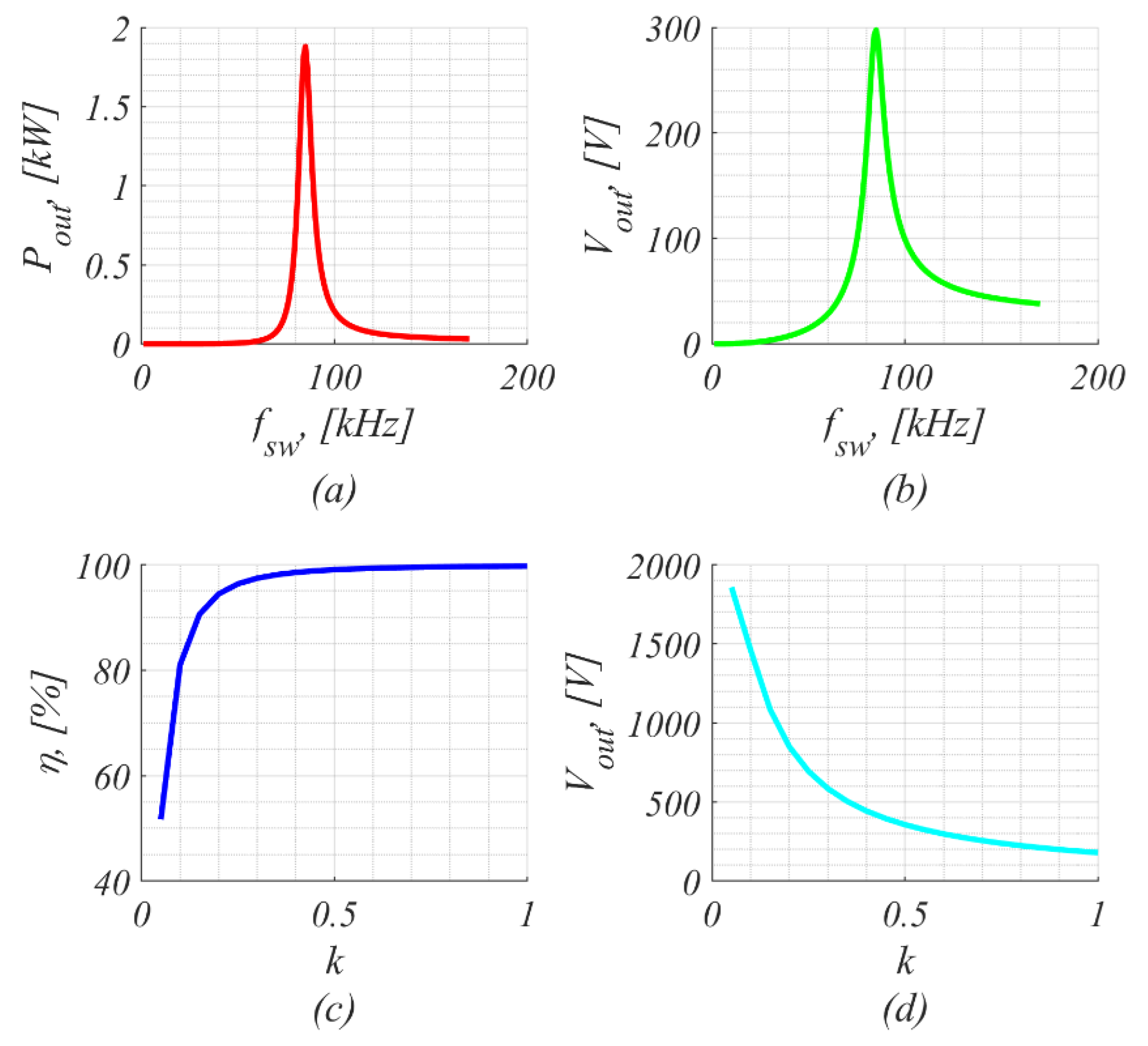
The most popular compensation methods are SS and SP. The SS type of compensation is preferable, as in this case, the compensation system remains in resonance for the cases of the variable coupling coefficient (
Figure 3). This enables resonance to be maintained even at valuable air gap variation. The drawback of this topology is that voltage gain is strongly related to the coupling coefficient (
Figure 3d), which leads to the necessity of a control output voltage. As can be seen in
Figure 3c, the operation at a low coupling coefficient yields a high level of loss. The output gain is also influenced by operating at a proper switching frequency to obtain maximum power delivery capabilities (
Figure 3a,b). Nevertheless, this also can be utilized to control the output parameters.
On the other hand, the SP type of compensation provides the possibility to maintain a constant output voltage. However, the compensation capabilities of this topology are limited by the coupling coefficient depending on the reflected impedance. This means that the system in this case should be tuned to the particular coupling coefficient (air gap), and any variation of these parameters would cause deviation from the resonance operation, which would cause a decrease in the output power rating and efficiency.
This means that in most of the reported solutions for vehicle charging based on WPT, SS compensation is used due to its ability to work with variable coupling.
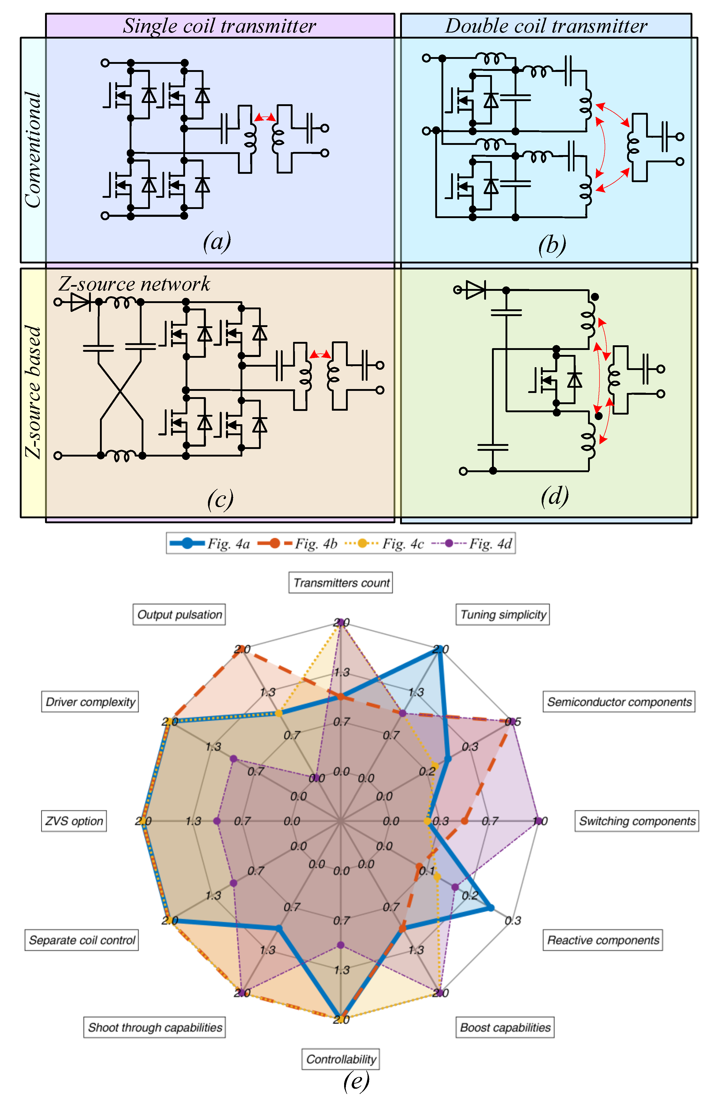
The second element to be chosen is the high-frequency inverter topology. Some of the topologies used in WPT are shown in
Figure 4.
The conventional solution based on a full-bridge inverter is shown in
Figure 4a. The advantage of this topology is high tuning simplicity and the possibility to implement various types of control (duty cycle, frequency, etc.). The topology in
Figure 4c extends the conventional solution by involving the Z-source network before the switching components [
27]. The Z-source network provides the topology with boost possibilities and increases reliability, as this topology does not suffer from the misalignment effect (where noise on transistor control signals can cause simultaneous opening of the transistor and shorting of the circuit).
The topology depicted in
Figure 4d has the same capabilities. In this case, the Z-source network covers all transmitter tasks by utilizing only one controlled element [
28,
29,
30]. Such topology has two transmitting coils, which enables an increase in the tolerance of the displacement of the receiver. However, the system operates solely in a shoot-through mode, which limits the possibilities to apply different control techniques. One of the methods to control the topology is to use pulse skipping control, which leads to concerns regarding the input and output parameter stability and the complexity of the output value filtering. Additionally, there is only one controlled component that does not enable separate control of each of the transmitters. Separate control of each transmitter can be implemented by the utilization of E-class converters (
Figure 4b). This provides the possibility to turn off one of the transmitters when the level of displacement is too high. The drawback of this topology is in the large number of reactive components and the complexity of tuning. The main parameters of the listed topologies are compared in
Table 2.
To perform a visual comparison between the constraints and limitations of the listed circuits, the list of criteria was composed as a spider plot (
Figure 4e). The parameters were scaled where the minimal values showed the worst solutions or solutions with limited capabilities of the chosen criteria; conversely, the solutions with better capabilities had the maximum value. The analysis involved additional parameters not listed in
Table 2.
The priority of each criterion is strongly dependent on the particular application. In further analysis, only the main parameters were taken into account as the basis to choose the topology. As the wireless charging system for a scooter operates at a fixed voltage, boost capabilities were not necessary.
Additionally, as further analysis mostly concentrated on the wirelessly coupled coils, the conventional solution (
Figure 4a) was chosen. In this case, the tuning operation is the simplest, as the circuit operates with the minimum number of reactive components and consequently the lowest cost.
3. Analysis of Coil Design Constraints
Taking into account data from
Table 1, we can specify the required parameters of the wireless charging station. As a multichannel charging station was considered with a target battery voltage not higher than 48 V, it was reasonable to design a single 48 V DC bus for supply. In this case, the most effective SS compensation approach was applied. The nominal switching frequency was selected to be equal to 85 kHz. According to these data, the nominal required mutual inductance to provide the desired 100 W per channel can be estimated from the load matching factor [
14]:
where the equivalent load can be estimated from the DC output voltage and power recalculated to the first harmonic:
As Q values of coils are high in the case of SS compensation, the mutual inductance can be calculated as follows:
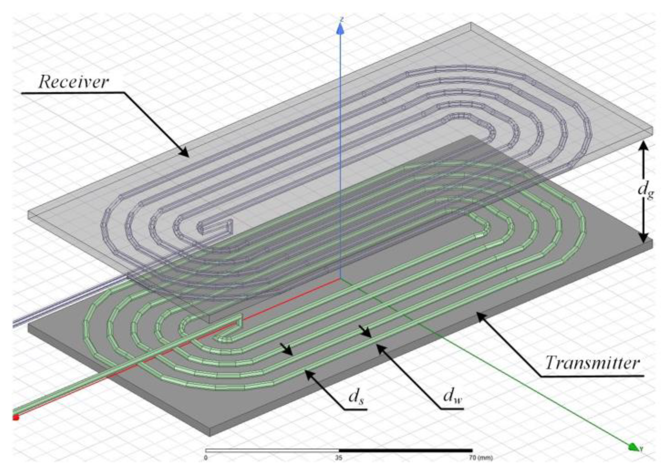
Based on these values, we can analyze the geometry of the coils. To analyze the limitations of coil design, a general FEM model with a high level of parameterization was developed. The simulations were performed in ANSYS MAXWELL 2021 (
Figure 5). The electrical parameters were simulated by the first harmonic approximation model [
31] using the Symbolical Math Toolbox in MATLAB R2022a.
The transmitter and receiver coil parameters were chosen to be the same. The same is true for the ferrite shielding dimensions, which remained the same for all of the solutions and defined coil sizes.
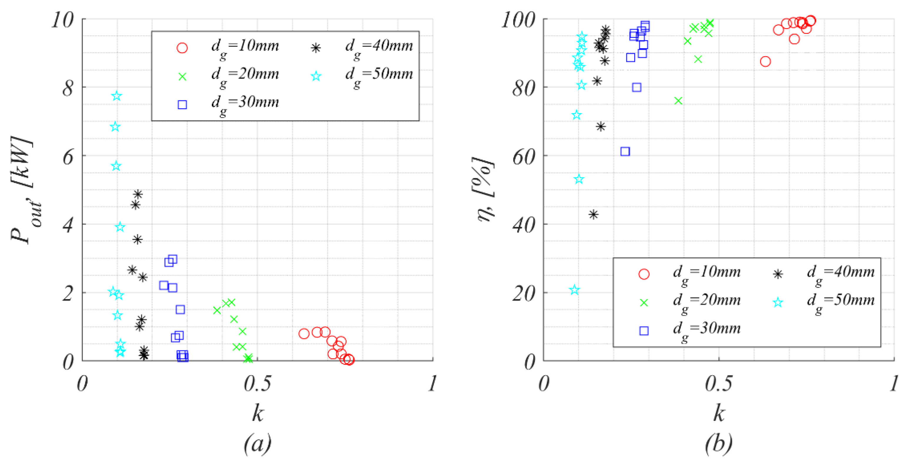
To analyze how the air gap between the receiver and the transmitter coil influences the output power and the system efficiency, we performed simulations on a set of solutions (
Figure 6). Air gaps of 10, 20, 30, 40, and 50 mm were simulated. Additionally, the variation in turn counts and wire diameter was included for each air gap. Each of the solutions was set to occupy the same coil area. The equivalent output load was tuned to work at 48 V of DC voltage.
The simulation results show that low levels of coupling coefficient (big air gap) enabled higher power rates to be transmitted than the high-coupling coefficients (small air gap). This was caused by the unloaded transmitter. On the other hand, such solutions yielded low levels of efficiency, which would gradually limit its application in real applications.
Also, it should be noted that in the solutions with big air gaps, the coupling coefficient was not gradually influenced by parameters like turn count and wire diameter.
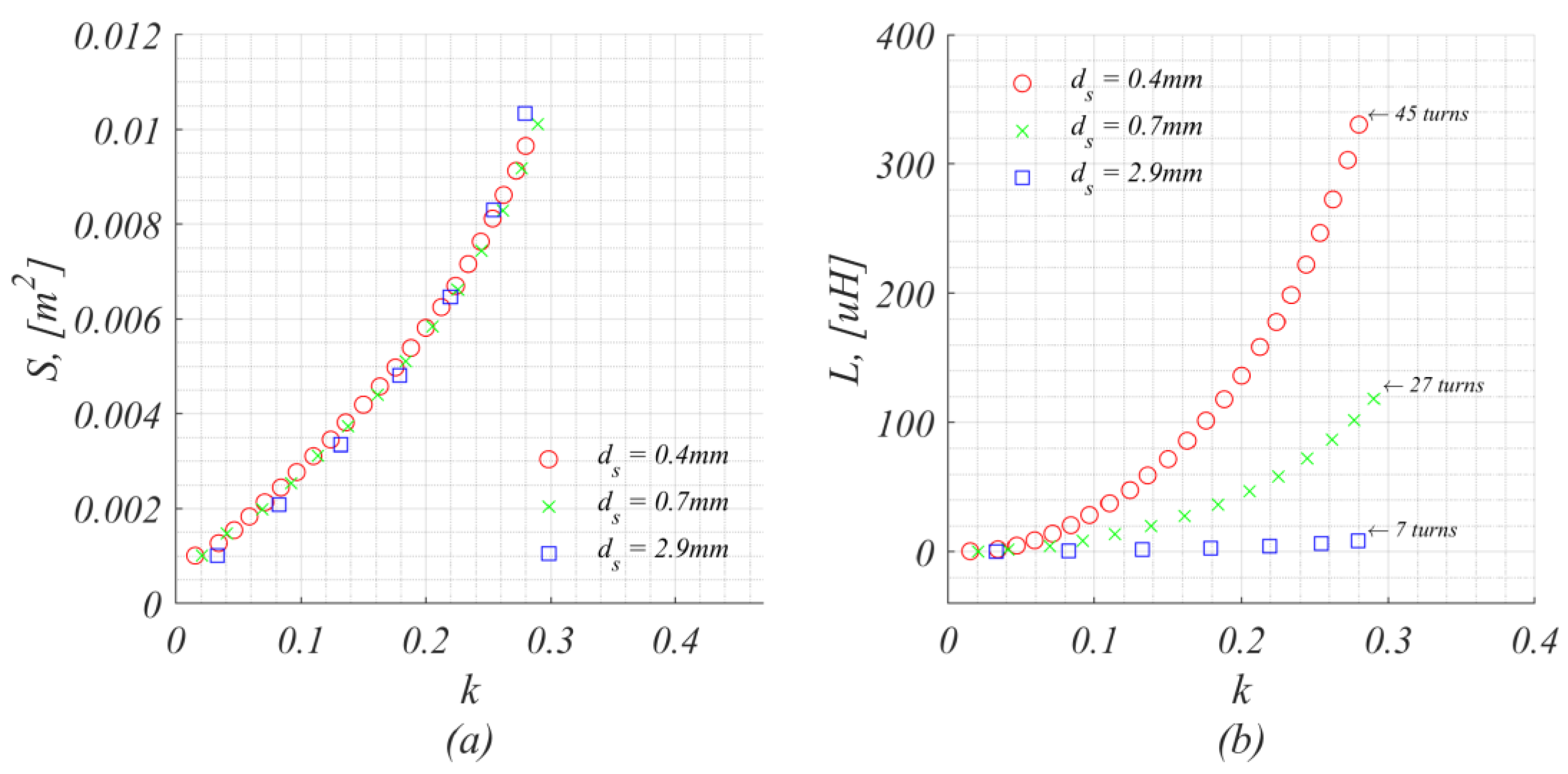
In order to analyze the influence of the occupied coil space on the coupling coefficient, a simulation for a fixed air gap of 30 mm was performed (
Figure 7). The area was calculated as coil width by coil length, which means that blank ferrite on the corners was also added to the coil space.
The simulation results show that the coupling coefficient was fully defined by the geometrical size of the coils and was not gradually influenced by the coil turns. This means that solutions with 45 and 7 turns, as shown in
Figure 7a, would have the same coupling coefficient if they occupy the same area. On the other hand, coil inductance would be influenced by the coil turns, as shown in
Figure 7b. The same would be true for the coil resistance.
The solutions with the maximum occupied area and comparably the same coupling coefficient were further simulated for different wire radiuses. This provided a set of solutions with the same air gap, coupling coefficient (5% deviation), and output voltage.
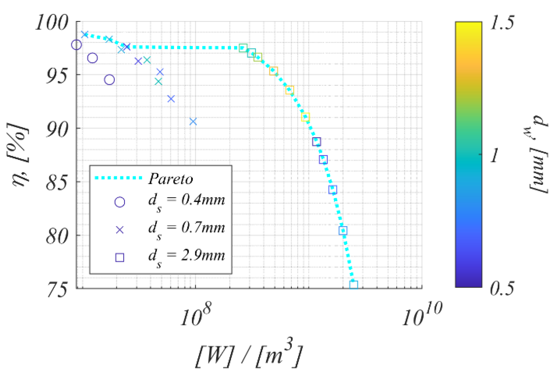
These solutions were analyzed in terms of volume-related power density (
Figure 8). The simulation results are shown below. The Pareto front shows that the best solutions in terms of a tradeoff between the efficiency and the volume-related power density could be obtained for a big step between the turns and the big diameter of the wire.
4. Experimental Verification
From the simulation results, we conclude that varying coupling coefficients lead to significant size redundancy. In simple terms, in order to provide the same charging power, the mutual inductance between the coils has to be the same, and in case of significant misalignment or distance increase, the size of coils has to be very large. This makes this solution not feasible against conventional wired charging solutions.
At the same time, if misalignment is absent, the size is obviously redundant, and in order to decrease power, switching frequency control has to be applied. This means that in order to provide a cost-effective charging station, the misalignment has to be minimized. In this case, the single-coil solution with a simple H-bridge is considered to be the optimal solution.
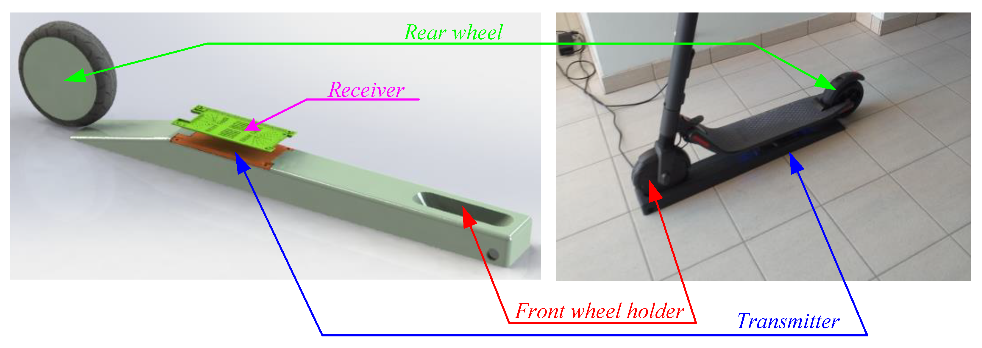
The prototype of the scooter charging station is shown in
Figure 9. The scooter is fixed on a special ramp with the transmission system. The height of the ramp decreases the air gap between the receiver and the transmitter. This ramp also works as a front wheel holder to fix the scooter and perfectly align the receiver and the transmitter to exclude any energy losses.
Such a construction allows for minimal distance to be maintained and the impact of misalignment to be minimized. Also, one of the main aspects of such a system is that it will mostly work outside, where the influence of different factors can cause component parameter degradation. The designed docking station has a waterproof concept that minimizes the influence of these factors.
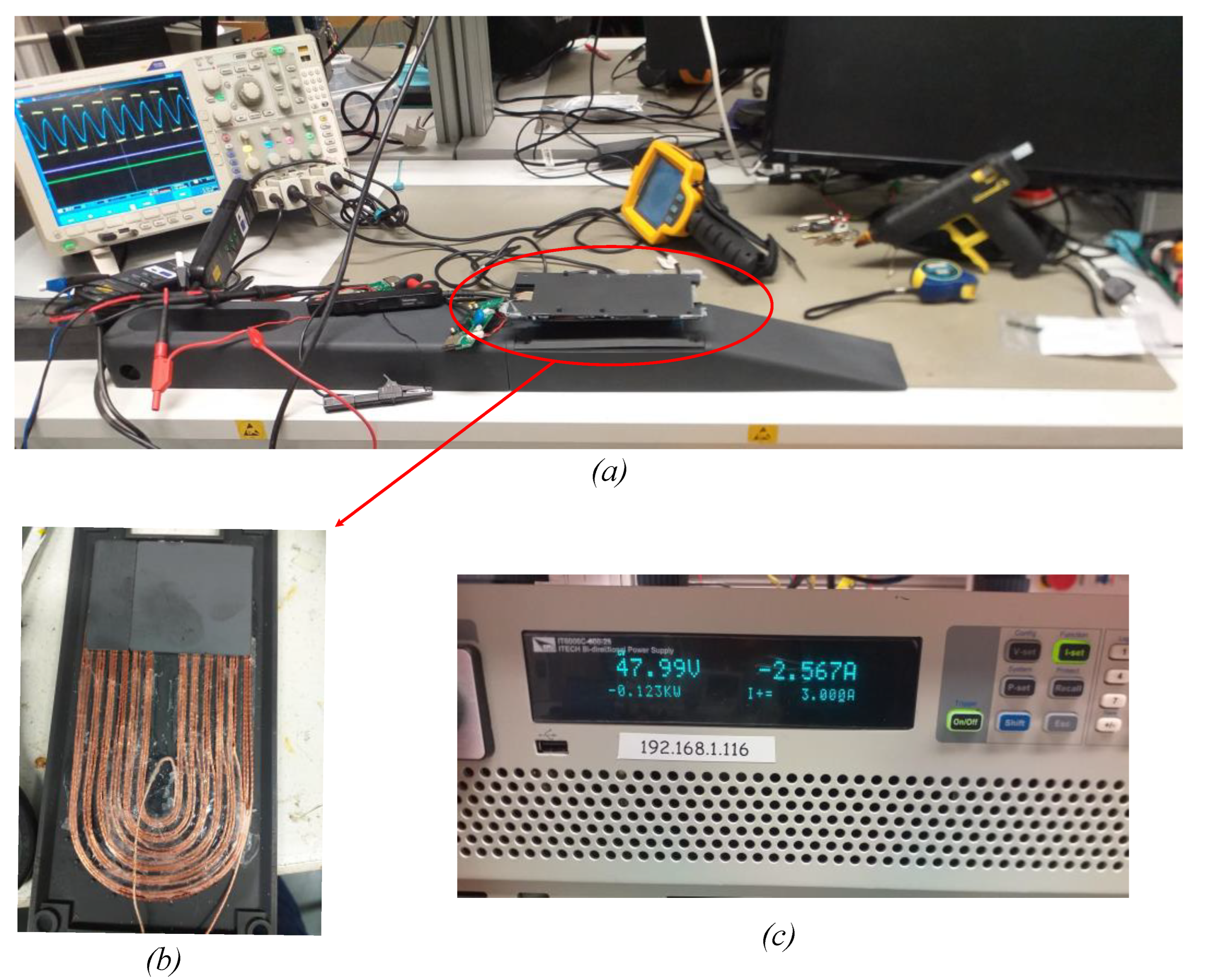
Figure 10 shows the experimental setup. It shows a general view of the experimental tests (
Figure 10a), when oscillograms and efficiency were measured. Also, it shows the coils (
Figure 10b) and the battery simulator (
Figure 10c) used during testing and tuning.
Figure 10 summarizes the details of the experimental verification.
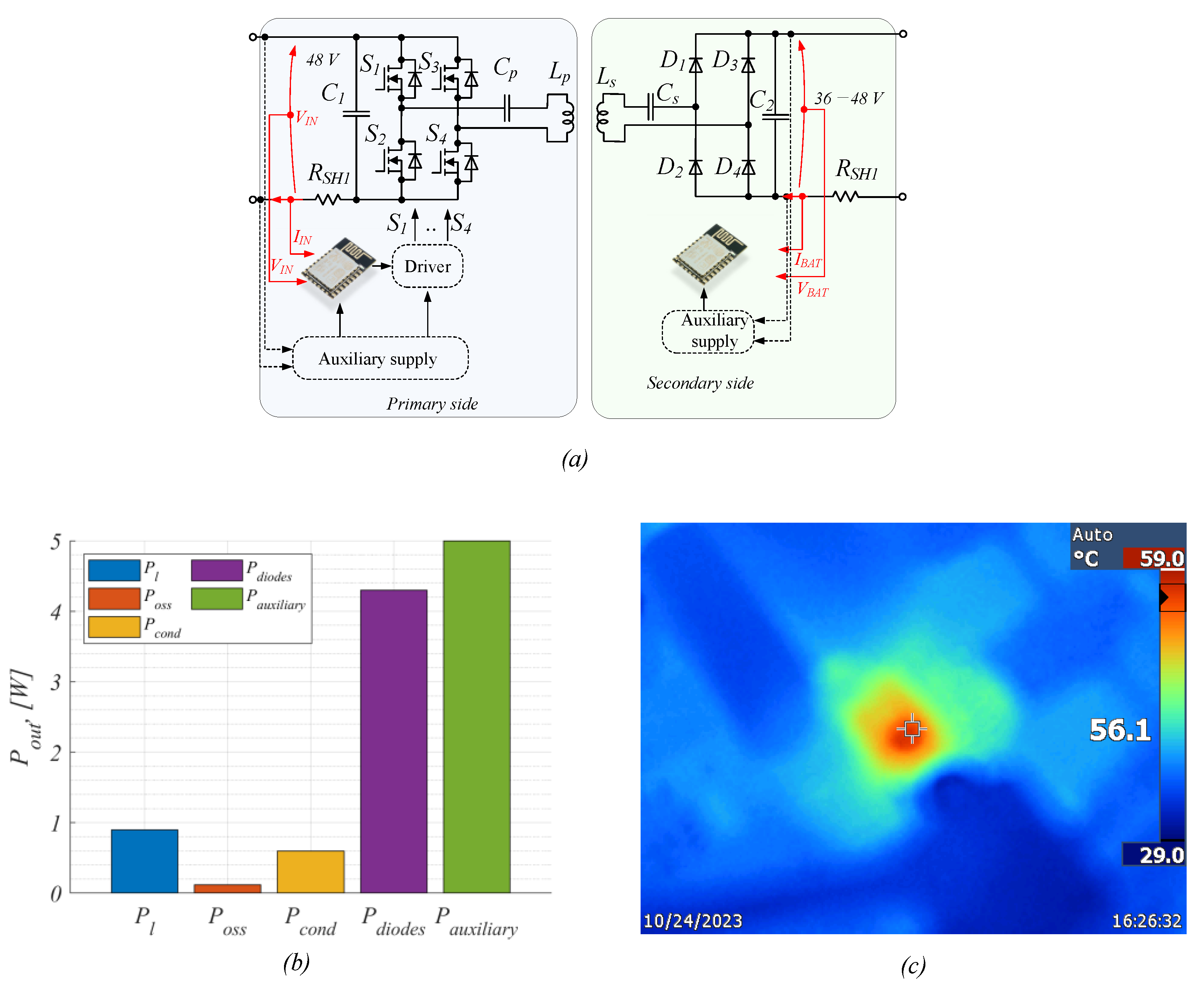
Figure 11a shows the structure of the developed experimental prototype of the scooter charger. The cost and feasibility of the concept were the priority in the design procedure. A very simple closed-loop control was carried out. The control itself is based on the ESP-WROOM-32 unit, which provides measurement sensing, switching of semiconductors, and communication with an external control source via Wi-Fi. At the same time, indirect output voltage control is needed and implemented if the receiver is not responding. This is carried out via input current and voltage measurement by a simple resistor divider for voltage and shunt resistor RSH, which are also used for output and input power control.
Table 3 shows the component list and specifications. The primary-side PCB (transceiver) has a control unit, a cheap non-isolated multichannel driver, and Si transistors. Also, there are ceramic capacitors that play the role of a resonance capacitor and input DC link. An auxiliary supply is provided via simple non-isolated cheap and external inductors.
BUK9K29-100E transistors were used with a maximum drain current of 30 A, a maximum drain-to-source voltage of 100 V, and a drain-to-source resistance at 25 °C, equal to 25 mOhm. The transistors have low thermal resistance in a small package. The transistors are located at the bottom of the PCB without additional radiators.
Figure 11b,c demonstrate the efficiency and thermal study. It can be seen that the hottest temperature corresponds to the secondary-side PCB and, in particular, to the diodes. At the same time, the transformer coils are the coldest elements in the power path. This means that this solution has a significant reserve in terms of possible maximum power increase. All the measurement results were obtained by voltage probes Tektronix TPA-BNC, current probes Tektronix TCP0150, and the digital oscilloscope Tektronix MDO4034B-3. For testing different voltage levels and operating points, a Chroma 62150H-1000S power supply was used.
Figure 11b shows loss distribution at 130 W transmitted power, where Pl—losses in coils, Poss—switching losses in primary-side transistors, Pcond—conduction losses in primary-side transistors, Pdiode—diode losses, and Pauxiliary—losses in auxiliary supply (maximum consumption during communication).
It can be concluded that the experimental efficiency reached around 95%, which is a significant result, taking into account that cost is a design priority and losses in auxiliary supply are unavoidable.
Figure 12 demonstrates the experimental waveform of the presented solution of the primary and secondary sides. The very first picture (
Figure 12a) shows the idle operation mode when the scooter is removed and pure reactive power is observed. After several seconds of scooter absence, the control system switches the transistors off in order to avoid energy loss. During the experiment, the maximum transmitted power was 130 W under the operating frequency of 85 kHz. This corresponds to
Figure 12b, which shows the primary and secondary coil voltage/current, and to
Figure 12c, where the battery voltage and current are shown.

