Abstract
This study proposes a hybrid pitching motion for oscillating flat plates aimed at augmenting the energy extraction efficiency of an energy harvester. The proposed hybrid pitching motion, within the first half cycle, integrates a non-sinusoidal movement starting at t/T = 0 and progressing to t/T = 0.25, with a sinusoidal movement initiating after t/T > 0.25 and continuing to t/T = 0.5. The second half of the cycle is symmetric to the first half but in the opposite direction. The calculated results show that the proposed hybrid pitching motion outperforms both the sinusoidal and the non-sinusoidal motions. The hybrid pitching motion merges the merits of both the sinusoidal and non-sinusoidal motions to optimize pitch angle variation. This integration is pivotal for enhancing the overall power output performance of an oscillating energy harvester characterized by momentum change that enhances the orientation of the heaving movement, smoother motion transitions, and consistent energy harvesting. The power generation is obtained at wing pitch angles of 55°, 65°, 70°, 75°, and 80° during a hybrid pitching motion. The proposed hybrid pitching motion, set at a pitch angle of 70°, achieves a maximum power output that exceeds the oscillating flat plate using a sinusoidal pitching motion by 16.0% at the same angle.
1. Introduction
The global emphasis on renewable and pollution-free energy sources, such as solar, wind, and hydropower, is essential for environmental conservation, enhancing human life quality, and promoting the renewable energy sector [1,2]. This transition away from traditional fossil fuels, such as natural gas, coal, and oil, toward renewable energy sources has catalyzed the development of numerous innovative technologies, among which flapping foil technology has emerged as a notable solution due to its eco-efficiency in harnessing energy from natural water and air currents. Although the exploration of hydro/aerodynamics in energy extraction through oscillating devices is relatively young, the foundational concept dates back to 1981 with the work by [3]. Their research focused on harmonically oscillating wings and combining pitch and plunge motions to extract wind energy, achieving efficiencies comparable to those of conventional windmills. In recent times, there has been a surge in interest regarding the energy-harvesting capabilities of oscillating foils.
Conducted experimental and numerical studies on a NACA0012 foil using an unsteady panel method revealed that optimal plunging amplitude and frequency could yield total energy extraction efficiencies reaching up to 30% [4]. Following this, a comprehensive parametric analysis revealed that enhancing pitching amplitude under constant plunging conditions could transition the system from consuming to generating power [5]. Research on a NACA0015 airfoil, utilizing FLUENT, demonstrated a peak efficiency of 34% within certain frequency and pitching amplitude ranges by adjusting the pitching motion, proving it to be more effective than plunging alone in improving energy extraction efficiency [6]. Recent advancements in piezoelectric energy harvesting have led to more efficient designs, such as the U-shaped harvester [7] and the semi-submersible model [8]. Another study has shown that the efficiency of an oscillating energy harvester is influenced by foil kinematics, system geometry, flow physics, and motion trajectory [9,10].
Energy harvesting from oscillating wing arrangements can be managed through two primary flow management strategies, passive and active management, depending on the need for extra energy within the flow field. Passive management enhances energy harvesting by incorporating simple modifications onto the airfoil surface without the need for additional energy input, offering a cost-effective and easily implementable solution. The flexible deformation enhances vortex movement on the suction side of the foil, boosting heaving force and energy efficiency by modifying pressure differentials around the foil [11]. Incorporating a Gurney flap increases the creation of vortices at the trailing edge and amplifies the pressure difference across the wing surface, enhancing lift force and leading to a substantial 21% enhancement in energy harvester [12]. A fully passive oscillating wing in free surface flow was explored, aiming to identify ideal submersion levels and the effects of single-frequency waves [13]. A feedback control system was proposed to regulate the angle of attack, aiming to boost lift force and thereby enhance power output [14]. A shroud enhances oscillating foil power extraction efficiency by 35.8% over an unshrouded counterpart [15]. A study revealed that inflexible plates enhance performance at low Reynolds numbers while flexible plates maintain high efficiency at higher Reynolds numbers [16].
Conversely, active management techniques, like flow regulation [17] and plasma devices [18], excel in real-time adjustments, surpassing passive techniques. The use of a fully deformable flapping foil showed a notable 2% increase in power output over the conventional foil setup [19]. Flaps have been used to increase the energy performance of oscillating energy harvesters. Energy extraction from an oscillating harvester featuring a trailing edge length of 20% of the chord revealed an 11% power increase compared to an oscillating wing without a flap by optimizing flap and wing angles to 35° and 70° [20]. A study conducted to enhance energy harvesting with an oscillating flat plate and trailing-flap found that enlarging the trailing flap on an oscillating flat plate enhances both power output and efficiency, with an increase of 26.9% in output power and 21% in efficiency occurring at a flap length of 60% [21]. The authors studied integrating a leading-edge flap in oscillating wing harvester and revealed configurations that boost power by 29.9% and efficiency by 23% [22].
The connection between the efficiency of flapping foil energy harvesters and wake stability has been emphasized by [23]. The energy performance of oscillating wing harvesters has been investigated in tandem arrangements by many authors. An inter-foil spacing within a tandem hydrofoil configuration has been found to provide stable energy extraction for the upstream foil, regardless of spacing, whereas the downstream foil’s energy extraction showed periodic variations with increasing separation, despite a constant motion phase shift [24]. A numerical analysis showed that a novel tandem airfoil configuration oscillating within a convergent duct enhances power extraction efficiency due to the effect of wall confinement [25]. In another study, adjusting the downstream spacing in tandem/parallel coupled oscillating wings can enhance energy extraction, resulting in a 23% increase in efficiency by adjusting the vertical inter-foil spacing. This highlights the importance of spatial optimization [26]. A concept of a tandem hydrofoil-based tidal array has been introduced, characterized by enhanced density and cost-effectiveness [27]. The principles of stability have been investigated, particularly in their relevance for designing and analyzing such configurations [28,29,30,31].
Hydraulic energy holds significant appeal due to its vast potential for reliable power delivery. In advancing sustainable energy solutions for unmanned marine devices, significant progress has been made in efficiently harnessing ultra-low-frequency pitch vibrations, achieving an energy extraction efficiency of 33.23% [32]. The effects of angle of attack variations on flapping foil propulsion efficiency in aquatic environments have been investigated, offering a detailed analysis of the hydrodynamic mechanisms that enhance our understanding of biomimetic propulsion technologies [33]. Research on optimal propulsion profiles for Micro Air Vehicles and Autonomous Underwater Vehicles has underscored the correlation between angle of attack variations and propulsion efficiency [34]. Additionally, the analysis of oscillating foil dynamics in fluids has shown how adjustments to the angle of attack affect propulsion efficiency, which is crucial for the design and optimization of propulsion systems for Micro Air Vehicles and Autonomous Underwater Vehicles [35]. Various deflector designs have been explored to enhance power output in flapping foil energy harvesters, focusing on the angle of attack and the distance of upstream deflectors to the hydrofoil, highlighting their impact on power generation efficiency [36]. The influence of stratified density flow on energy output was analyzed, particularly in relation to pitching movement amplitude [37].
Energy extraction performance can be significantly improved with an appropriate combination of pitching and heaving motions. The energy extraction performance has been investigated by modifying foil trajectories and positions, emphasizing favorable wake interactions for efficiency improvement [38]. The performance of power extraction by an oscillating hydrofoil was evaluated across three distinct movements at a Reynolds number of 1.7 × 10⁶: left swing, right swing, and linear. It was determined that the left-swing motion yielded superior power extraction compared to both the right-swing and linear motions [39]. The non-sinusoidal motion showed maximum output power over the sinusoidal motion [40]. The non-sinusoidal pitching and plunging motions have been examined to show how flapping foil energy extraction markedly improved [41]. Research on a sinusoidal motion found optimal efficiency for a flapping foil at a pitching angle = 75° and a reduced frequency = 0.16, surpassing 33% energy efficiency [42]. The influence of the non-sinusoidal motion on efficiency enhancement has been investigated, finding = 75° and = 0.16 to be optimal, yielding 32% efficiency [43]. Semi-active flapping foils with cosinusoidal pitching motions enhanced energy harvesting efficiency [44].
In exploring the practical application of the proposed hybrid pitching motion, this study draws parallels with findings from related aerodynamic studies, such as those by [45], who illustrate how variable amplitude and phase angles can enhance aerodynamic efficiency, which is central to the design principles of this study. Similarly, strategic structural modifications have been shown to amplify energy harvesting outputs, as evidenced by the empirical findings of [46]. The methodology of this study is complemented by [47], which demonstrates how specific motion parameters affect fluid dynamics and energy extraction efficiency. Insights into the aerodynamic behaviors at low Reynolds numbers, crucial for refining our energy harvesting approaches, are provided by [48]. Exploration of the enhancement of vibrational energies through flow modifications is provided by the findings of [49]. Collectively, these studies corroborate the viability of our hybrid pitching motion, affirming that our theoretical innovations have a strong foundation in practical, empirically tested aerodynamics.
The aim is to investigate the potential of using a proposed hybrid pitching motion combining non-sinusoidal and sinusoidal pitching motions with heaving motion in oscillating flat plates to enhance energy harvesting performance. A quantitative assessment was undertaken to examine the impact of various pitch angles 55°, 65°, 70°, 75°, and 80°. This comprehensive investigation provided insights into the importance of modifying flat plate trajectories for improving the performance of energy harvesters.
2. Numerical Methodology
The simple geometry of a rectangular flat plate emphasizes its superior performance over the profiled airfoil [50]. It also provides maximum power and efficiency conditions for an oscillating wing and has the following key values: the chord length of the wing, c = 1; the location of the pivot, = 0.3333; the amplitude of the heaving motion /c = 1; the maximum of the pitch angle = 75°; the difference of the = 90°; and a reduced frequency of = 0.14.
Figure 1 shows a schematic of a 2D flat plate with a foil chord span of c, thickness and 4% of the chord length. The proposed hybrid pitching motion investigates energy extraction efficiency at the same conditions of reduced frequencies = 0.14, pitch angle = 75°, = c/3, and /c = 1.0 plunging amplitude that provides the optimal power and efficiency as mentioned in [50].
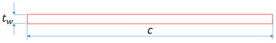
Figure 1.
Illustrations of an oscillating flat plate energy harvester.
Figure 2 shows the variation of instantaneous pitching angle θ(t) in one period with sinusoidal pitching profiles, as depicted in Figure 2a. Figure 2b,c show the non-sinusoidal and the proposed hybrid pitching motions as a function of the parameter β, which systematically transition from β = 1.0, 1.5, 2.0, 2.5, 3.0, and 4.0 with a 90° phase lag the heaving motion. The sinusoidal, the non-sinusoidal, and the proposed hybrid pitching motions are expressed as Equations (1), (2), and (3), respectively; ω = 2πf is angular oscillating frequency, and T = 2π/ω is time.
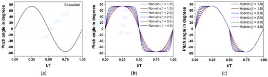
Figure 2.
Instantaneous pitching θ(t) in a cycle for (a) sinusoidal; (b) non-sinusoidal; and (c) the proposed hybrid motion at /c = 1.0 and = 75°.
Figure 2a and Equation (1) show the profiles of the instantaneous pitching amplitude θ(t) for the sinusoidal motion [50], where the pitch angle increases and decreases in a regular pattern over time. The flat plate reaches its highest point on the graph at (t/T = 0.25), representing the maximum positive pitch angle () in the first half of the cycle. Subsequently, the flat plate reaches the horizontal position at (t/T = 0.5), while the lowest point represents the maximum negative pitch angle (−) at (t/T = 0.75) in the second half of the cycle.
Figure 2b and Equation (2) show the characteristic behavior of the instantaneous pitching amplitude, θ(t), for non-sinusoidal motion that is engineered by integrating a specially designed trapezoidal-like pitching profile modulated by an adaptable parameter β, as described in [51]. Notably, when the modulation parameter β = 1.0, the resultant pitching motion closely approximates a sinusoidal profile with a phase lag of 90º behind the heaving movement. As the amplitude remains constant, deviations of β from 1.0 result in an extended duration, where θ(t) sustains the peak values of . This effect becomes increasingly pronounced as β ascends toward infinity (β ), with the profile tending toward a square wave.
Figure 2c and Equation (3) illustrate the proposed hybrid pitching motion, ingeniously synthesizing the attributes of both the non-sinusoidal and sinusoidal motions delineated previously in Equations (2) and (1), respectively. Within this framework, the flat plate exhibits an early swift ascent to the maximum pitch angle via the non-sinusoidal trajectory in the initial quarter of the cycle (0 ≤ t/T ≤ 0.25). Thereafter, from the midpoint of the ascent to the return to the horizontal position (0.25 < t/T ≤ 0.5), the motion adheres to a sinusoidal path. Figure 2c displays the progression of the pitching motion, θ(t), across a range of β values, marking a shift from an almost sinusoidal motion when (β = 1.0) to a more pronounced, half-square waveform as the value of β increases. This transition is particularly notable at the t = 0.25T mark, where the maximum pitch angle is observed. The parameter β acts as a key factor for non-sinusoidal and hybrid motions influencing the time intervals at which the pitch amplitude reaches its extreme values. For instance, in a sinusoidal pitching motion, the maximum pitch angle occurs at t/T = 0.25 of time. However, with the proposed hybrid motion (β = 1.5), the maximum pitch angle reaches slightly earlier, at t/T = 0.23, indicative of an enhanced power generation performance.
Figure 3 shows the time variations of the pitching profile θ(t) for an oscillating flat plate. The pivot point is 0.33c from the leading edge, in line with the centerline of the flat plate. The upstream flow velocity is represented as . Due to the rapid pitching motion at the non-sinusoidal and proposed hybrid motions, the flat plate attains higher angles compared to the sinusoidal pitching motion. The flat plate undergoes heaving motions, represented by h(t) in Equation (4), with h and denoting the immediate and maximum vertical oscillations of the wing, respectively.
where is the fluid density, c is the chord length, is the free-stream velocity, and μ is the dynamic viscosity. The two-dimensional unsteady numerical simulation was conducted at Reynolds numbers 500,000 to analyze the performance of the energy harvester.
where f* = fc/U∞ is reduced frequency.
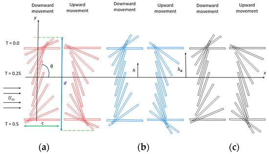
Figure 3.
Kinematics of the oscillating flat plate: (a) sinusoidal; (b) non-sinusoidal (β = 1.5); and (c) hybrid (β = 1.5) at /c = 1.0 and = 75°.
The instantaneous power (P) is integrated over a cycle to determine the average power (), which is used to measure the energy production.
here, Y(t) denotes the force in the vertical direction, M(t) represents the pitching moment, and T stands for the period of oscillation.
here, (t) represents the instantaneous pushing coefficient and (t) indicates the instantaneous momentum coefficient, which are determined as follows:
The average power coefficient over a cycle is calculated by the integration of instantaneous over a cycle.
or
Equations (10) and (14) reveal that and represent the pushing-based energy extraction, while and signify the moment-based contribution.
The calculation of the power extraction efficiency can be performed utilizing Equation (15).
where d is the greatest displacement in the y direction of a flapping plate.
The overset mesh method was utilized, which is well-suited for modeling massive body movements, intricate forms, and multi-component structures [52]. To simulate flow over the oscillating wing, the unsteady incompressible Reynolds-averaged Navier–Stokes (RANS) flow equations were utilized in Fluent software version 21 R1 [53]. The simulation employed the finite volume method and a pressure-based solver. The governing equations are defined by Equations (16) and (17).
and represent the velocities. In Equation (17), the Reynolds-stress term is computed through the k-ω SST turbulence model by previous investigators in comparable investigations [52,54]. Spatial discretization for pressure, momentum, and turbulent viscosity resolution is accomplished using the second-order upwind method. Flat plate motion was input through defined functions of the user (UDF), and grid movement was executed using the method of dynamic mesh. The y+ value was set to meet the requirements of the turbulence model used, ensuring precise resolution of the boundary layer. In this study, a y+ value of 5.0 yielded a total output power coefficient of 1.04. This closely aligns with the results obtained using a y+ value of 0.98, where the total power coefficient was 1.05.
Figure 4 presents the rectangular computational region, meshing structure, subdivided mesh, and external constraints utilized for simulating this case study. An investigation into domain independence was conducted with the length, l, and the width, b, of the numerical domain. The range for l is from −20c to 50c, and for b, from −25c to 25c was chosen, as further increasing the simulation area had no influence on the results. The pressure for the exit point of the boundary was positioned at 50c, while the top and bottom boundaries were subjected to a slip boundary condition, as depicted in Figure 4a. The wing’s main body (highlighted by the rectangular region in blue) in Figure 4b was associated with moving grids and the detailed view of mesh near wing wall corners. The moving grid region took the form of a rectangular grid with a length of 6c and a width of 5c. The model utilized 2000 time steps for each oscillation period, with the outcomes being charted following the completion of seven cycles.
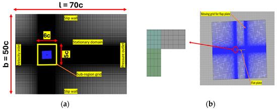
Figure 4.
Simulation space and grid model: (a) simulation space and (b) moving area and the magnified view of the meshed computational domain near the corner of the wing wall.
Mesh independences were carried out with three different groups of structured meshes: coarse, medium, and fine mesh. The effect of grid resolution and the time step on the calculated value is presented in Table 1 and Table 2. For grid independence tests, three sets of structured grids were utilized within the overset mesh framework. Firstly, for the moving grid, a coarse grid consisting of 0.6 × elements, a medium grid with 1.2 × elements, and a fine grid comprising 2.6 × elements were employed. Secondly, for the background, a coarse grid of 0.3 × elements, a medium grid of 0.6 × elements, and a fine grid of 1.2 × elements were used. For the time step independence study, the medium mesh was employed with time intervals of 500, 2000, and 4000 for each cycle. Table 1 and Table 2 show the power output coefficient and relative variation of power output coefficient over time for different mesh sizes and time steps, respectively. The medium-mesh resolution satisfies the accuracy in space and nearly agrees among different time steps.

Table 1.
Grid independence analysis.
Table 2.
Grid time step independence analysis.
In validating the numerical model and mesh, a comparison with the results from [50] and [20] was conducted, revealing a favorable agreement, as depicted in Figure 5. Based on these results and to balance between precision and processing time, we opted for a medium of 1.2 × and 2000 time steps per cycle for the simulation of the new proposed non-sinusoidal motion.
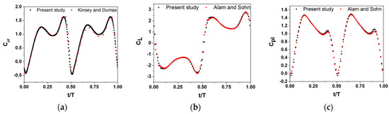
Figure 5.
Comparison of the numerical results and the present study and the validation data: (a) pushing power coefficient for an oscillating plate at Re 1.1 × by Usoh et al. [50]; (b) pushing force coefficient at Re 500,000 by Alam and Sohn [20]; (c) pushing power coefficient at Re = 500,000 by Alam and Sohn [20].
3. Results and Discussions
3.1. Output Power and Efficiency
This study investigates the performance of output power from flapping energy harvesters through the application of the proposed hybrid pitching motion, varying the parameter β and pitching angles under = 0.14 and /c = 1.0. Table 3 summarizes the , , and over one cycle for quantitative comparison.
Table 3.
The instantaneous , , and for sinusoidal motion, non-sinusoidal motion, and hybrid pitching motions at different values of β for = 75° and = 0.14.
In Table 3, the proposed hybrid motion (β = 1.5) shows the maximum extraction power, = 1.15, and efficiency = 40.78%, respectively, at the optimum pitch angle of = 75° [50], = 0.14, and /c = 1.0.
Table 3 shows the analysis of efficiency across different pitching motions and values of β for a pitch angle of 75º, revealing significant variations in performance. The sinusoidal motion establishes a baseline efficiency of 40.31%. In comparison, the non-sinusoidal and hybrid motions demonstrate varying efficiencies due to an increase in the maximum vertical displacement, d, of the flapping flat plate, which directly impacts the efficiency. As β is 1.5, the hybrid motion of 40.78% is slightly higher than the sinusoidal and non-sinusoidal pitching motions.
Figure 6 shows the variation of , , , and η for the sinusoidal, non-sinusoidal, and hybrid pitching motions by changing the parameter β. The plot shows the hybrid motion surpassing the sinusoidal and non-sinusoidal pitching motions in total power extraction , pushing power, , and efficiency, β. In contrast, the moment power, , in the non-sinusoidal motion is higher than the sinusoidal and hybrid motions. At β = 1.0, the and η of the non-sinusoidal motion is slightly higher than those of the hybrid motion because the non-sinusoidal motion exhibits characteristics at β = 1.0 similar to those of the sinusoidal motion, as shown in Figure 2. However, excessively increasing β could reduce performance, such as β = 3.0 and 4.0. This could be seen in the calculated results that reveal that the efficiency of output power is defined by the contributions from the different combinations of , , and corresponding heaving and pitching velocities, all of which are affected by β values. For a specific nominal pitch angle, there is an optimal value of β at which the power output is maximized.
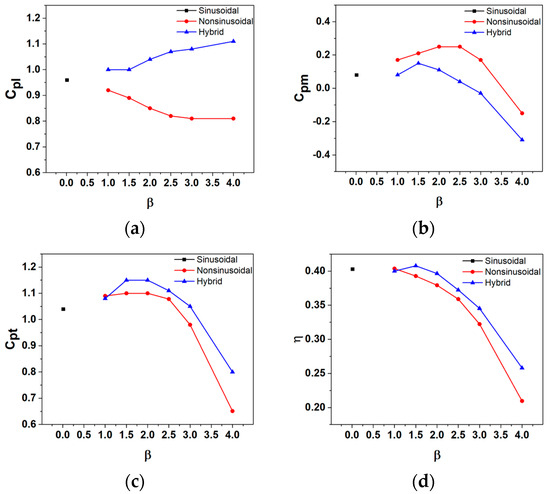
Figure 6.
Comparison of sinusoidal, non-sinusoidal, and the proposed hybrid pitching motions versus various values of β (a) pushing power coefficient; (b) moment power coefficient; (c) output power coefficient; and (d) efficiency at = 0.14 and = 75°.
The and values for the sinusoidal, non-sinusoidal, and hybrid pitching motions, evaluated at various pitch angles ranging from 55° to 80° with a constant reduced frequency = 0.14 and a heave amplitude to chord ratio /c = 1.0, are summarized and listed in Table 4. Although the full range of β values from 1.0 to 4.0 has been calculated for each pitch angle, only the values resulting from the optimum β values are shown in this table. Table 4 and Figure 7 illustrate that hybrid pitching motions consistently deliver higher power coefficient values compared to their sinusoidal and non-sinusoidal counterparts across identical pitch angles. The incorporation of hybrid motion attributes can substantially boost power generation specifically; at a 55° pitch angle, the hybrid motion (β = 3.0) achieves the highest relative increment of 68.6% in compared to the sinusoidal motion. The output power of the hybrid motion at a pitch angle of 70º demonstrates a 16% enhancement when compared to the sinusoidal motion with β = 2.0. In the case of the optimal pitch angle for a sinusoidal motion of 75° [50], the output power of the hybrid motion shows a 10.57% enhancement. At the pitch angle of 80°, the advantage of the hybrid motion is also evident, where it exhibits an 11.10% increment over the sinusoidal motion, despite both having a β value of 1.0. The trend across the data indicates that increasing the pitch angles in the hybrid pitching motions could enhance the power output of the system. Table 4 shows the values for each type of motion over a range of pitch angles.
Table 4.
Maximum output power coefficient for sinusoidal, non-sinusoidal, and hybrid pitching motions with different pitching angles at = 0.14 and /c = 1.0.
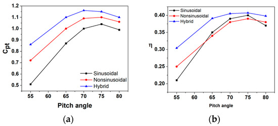
Figure 7.
Variation of (a) output power coefficient and (b) efficiency for different pitching amplitude and different values of β at ho/c = 1.0 and f* = 0.14.
Figure 7b shows the efficiency for the sinusoidal, non-sinusoidal, and hybrid pitching motions across varying pitch angles from 55° to 80°. The hybrid motions, combining attributes of both sinusoidal and non-sinusoidal dynamics, consistently achieve higher efficiencies throughout the range, peaking at 75°. The graph clearly demonstrates that the hybrid motions are consistently outperforming the other two types.
3.2. Mechanism of Energy Output Enhancement
Figure 8 shows the calculated results of ,, , , and for the sinusoidal motion and the function of β for the hybrid pitching motions. Figure 8a shows an enhancement in the pushing force coefficient across the oscillation cycle. contributes positively to the pushing power coefficient for every case of the proposed hybrid pitching motion.
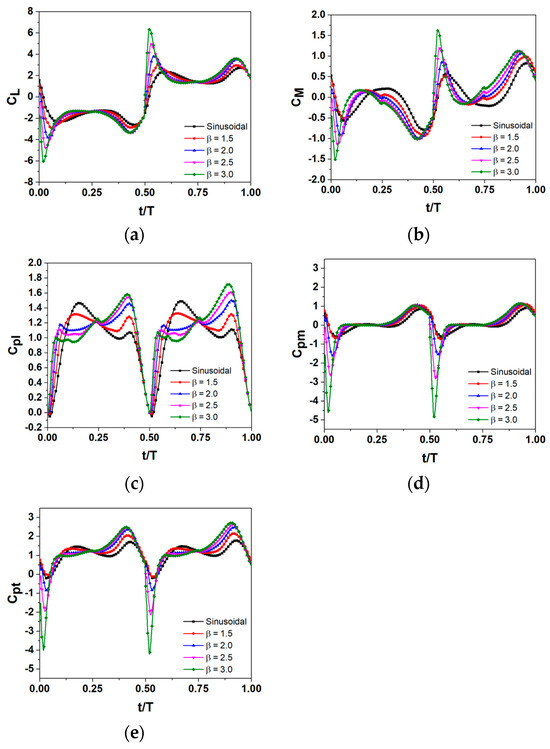
Figure 8.
Variations of (a) pushing force coefficients CL(t); (b) pitching moment coefficients CM(t); (c) instantaneous pushing power coefficient Cpl; (d) instantaneous moment power coefficient Cpm; and (e) instantaneous total power coefficient Cpt for sinusoidal and hybrid motions with different values of β at f* = 0.14 and θo = 75°.
Within the time interval (0.0 t/T 0.25), the rapid attainment of maximum pitch angles results in a heightened pushing power compared to the sinusoidal motion. As depicted in Figure 8a, following the peaks, the pushing forces coefficient of the hybrid motions drops to lower values compared to the sinusoidal pitching motion. The values for the hybrid pitching motions surpass those of the sinusoidal pitching motion until t/T = 0.015, indicating that increases with β. This can be attributed to the fact that as β increases, the flat plate reaches its maximum pitching angle more swiftly compared to the gradual approach of the sinusoidal motion, thereby resulting in an increase in , as shown in Figure 8c.
Figure 8b,d illustrate the pitching moment coefficient, (t), and the moment power coefficient, , with distinct peaks and valleys that align with specific phases of the oscillation cycle. Figure 8d shows that the moment power coefficient, , could reach its minimum value by increasing parameter β through the process loop.
Figure 8e presents the variations of , exhibiting its dependency on both pushing power and moment power coefficients across different pitching motions. At specific times t/T = 0.25 and t/T = 0.75, the coefficients related to the pushing force, pushing power, and total power show nearly identical values for both the sinusoidal and hybrid pitching motions. This result, as shown in Figure 8a,c,e, arises because the pitch angles are the same at these specific times for all pitching motion cases.
Figure 9 shows the streamline and vorticity contours in half of the cycle for sinusoidal, non-sinusoidal (β = 1.5), and hybrid (β = 1.5) at = 75°. Subsequent to the downward pitch, a leading-edge vortex (LEV) develops on the windward side. This vortex then disappears by the stagnation flow on the upper surface and generates the LEV on the leeward lower surface near t/T = 0.15. After this point and throughout the descent, the leading-edge vortex appears only on the leeward lower surface. During the initial quarter of the cycle (0.0 ≤ t/T ≤ 0.25), the vortex patterns observed in the hybrid and non-sinusoidal motions are alike. Conversely, during 0.25 < t/T ≤ 0.50, vortex shapes from the hybrid motion look similar to those from the sinusoidal motions.
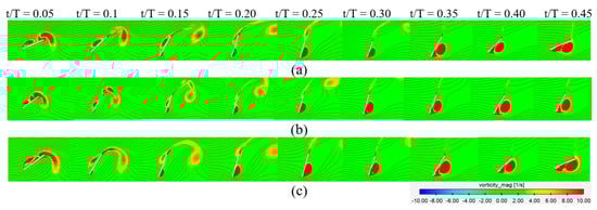
Figure 9.
Instantaneous vorticity and streamline plot within one period at different time steps for (a) sinusoidal; (b) non-sinusoidal (β = 1.5); and (c) hybrid (β = 1.5) with f* = 0.14 and θo = 75°.
Figure 10 shows the static pressure for three different pitching motions, sinusoidal, non-sinusoidal (β = 1.5), and hybrid (β = 1.5), at = 0.14 and = 75° in a flapping flat plate. It is evident that the pressure on the windward side of the plate exceeds that on the leeward side when the flat plate is descending between t/T = 0.0 and 0.50, thereby contributing favorably to pushing force for extracting flow energy. The pressure contours of the non-sinusoidal and hybrid cases look similar during 0.0 ≤ t/T ≤ 0.25, and the pressure contours of the sinusoidal and hybrid cases look similar during 0.25 < t/T ≤ 0.50. The detailed surface pressure distribution is plotted in Figure 11.
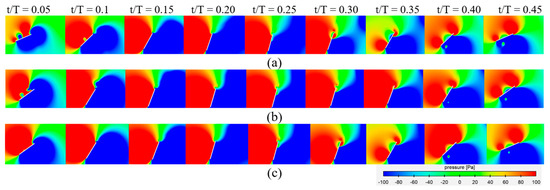
Figure 10.
Pressure contour plot evolution over one period at different time steps for (a) sinusoidal; (b) non-sinusoidal; (β = 1.5); and (c) hybrid (β = 1.5) with f* = 0.14 and θo = 75°.
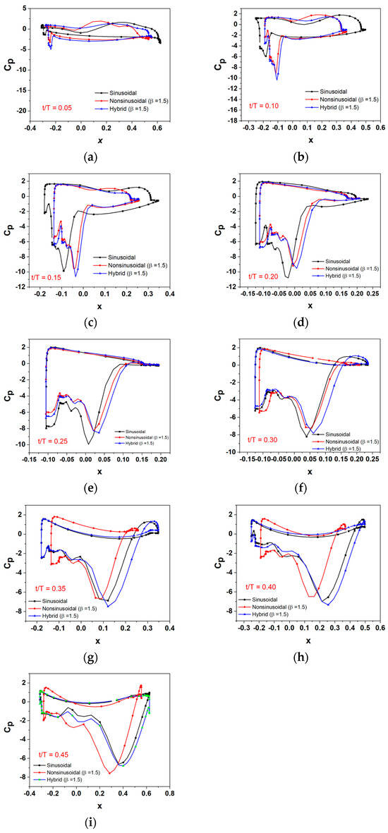
Figure 11.
Pressure coefficient distribution on a flat plate along the x-direction over one period at different time steps: (a) t/T = 0.05; (b) t/T = 0.10; (c) t/T = 0.15; (d) t/T = 0.20; (e) t/T = 0.25; (f) t/T = 0.30; (g) t/T = 0.35; (h) t/T = 0.40; and (i) t/T = 0.45 for sinusoidal; non-sinusoidal (β = 1.5); and hybrid (β = 1.5) with f* = 0.14 and θo = 75°.
The pressure distribution around the flat plate directly influences the enhancement of aerodynamic forces, such as pushing and moment, which are directly linked to energy extraction performance. Figure 11a shows that the hybrid and non-sinusoidal motions are distinguished by their higher pressure difference than sinusoidal differences at t/T = 0.05. Figure 11b,c show the calculated surface pressures at t/T = 0.10, and the pitch angles for both the hybrid and non-sinusoidal motions exceed those of the sinusoidal motion. In these cases, the increased pitch angles lead to a greater negative pressure on the leeward side of the plate. In the hybrid and non-sinusoidal motions, the projected length along the x-axis is shorter compared to the sinusoidal motion. As illustrated in Figure 11d,e for t/T = 0.20 and t/T = 0.25, respectively, the pitch angles of the sinusoidal, non-sinusoidal, and hybrid motions reach similar values, resulting in similar pressure distributions. This result is also reflected in the pushing force coefficient, pushing power coefficient, and total power output, as depicted in Figure 8a,c,e. The non-sinusoidal motion maintains a higher pitch angle during this time period (0.25 < t/T ≤ 0.50) compared to both the sinusoidal and hybrid motions. Because of the higher pitching angle, it exhibits a shorter projection length along the x-axis than the other cases. This short projection length results in a reduced pushing force, subsequently lowering the power output of the non-sinusoidal motion. This relationship is shown in Figure 11f–i.
4. Conclusions
This study introduced and investigated the proposed hybrid pitching motion for oscillating flat plates within an energy harvester framework, aimed at enhancing the efficiency of power extraction. The hybrid motion effectively combines the advantageous aspects and characteristics of both the sinusoidal and non-sinusoidal motions, yielding an optimized pitch angle variation that improves the performance of the harvester.
The numerical analysis demonstrated that the hybrid motion outperforms the traditional sinusoidal and non-sinusoidal motions across various wing pitch angles (55°, 65°, 70°, 75°, and 80°). Notably, the power output was improved by approximately 10.57% over the optimum condition for the oscillating flat plate at a wing pitch angle of 75°, underscoring the utility of this proposed approach. The maximum energy extraction for the proposed hybrid pitching motion was at a pitch angle of 70°, showing a 16.0% increase in power output compared to the same pitch angle condition in the sinusoidal pitching motion. The proposed hybrid motion presents a notable advancement in the field of energy harvesting, offering a viable path for improving the performance of oscillating flat plate harvesters.
Author Contributions
Conceptualization, S.S. and C.-H.S.; methodology, S.S.; software, S.S.; validation, S.S.; formal analysis, S.S.; investigation, S.S. and C.-H.S.; resources, C.-H.S.; data curation, S.S.; writing—original draft preparation, S.S.; writing—review and editing, S.S. and C.-H.S.; visualization, S.S. and C.-H.S.; supervision, C.-H.S.; project administration, C.-H.S.; acquisition of funding, C.-H.S.; All authors have read and agreed to the published version of the manuscript.
Funding
This study received funding from the National Research Foundation of Korea (NRF) funded by the Korean government (MSIT) under grant number 2022R1F1A1061903.
Data Availability Statement
The data presented in this study are available on request from the corresponding author.
Conflicts of Interest
The authors have disclosed that they have no potential conflicts of interest.
References
- García-Olivares, A.; Solé, J.; Osychenko, O. Transportation in a 100% renewable energy system. Energy Convers. Manag. 2018, 158, 266–285. [Google Scholar] [CrossRef]
- Paiva, A.S.S.; Rivera-Castro, M.A.; Andrade, R.F.S. DCCA analysis of renewable and conventional energy prices. Phys. A Stat. Mech. Its Appl. 2018, 490, 1408–1414. [Google Scholar] [CrossRef]
- McKinney, W.; DeLaurier, J. Wingmill: An oscillating-wing windmill. J. Energy 1981, 5, 109–115. [Google Scholar] [CrossRef]
- Davids, S.T. A Computational and Experimental Investigation of a Flutter Generator; Naval Postgraduate School: Monterey, CA, USA, 1999. [Google Scholar]
- Jones, K.; Platzer, M.; Jones, K.; Platzer, M. Numerical computation of flapping-wing propulsion and power extraction. In Proceedings of the 35th Aerospace Sciences Meeting and Exhibit, Reno, NV, USA, 6–9 January 1997; p. 826. [Google Scholar]
- Kinsey, T.; Dumas, G. Parametric study of an oscillating airfoil in a power-extraction regime. AIAA J. 2008, 46, 1318–1330. [Google Scholar] [CrossRef]
- Aramendia, I.; Saenz-Aguirre, A.; Boyano, A.; Fernandez-Gamiz, U.; Zulueta, E. Oscillating U-shaped body for underwater piezoelectric energy harvester power optimization. Micromachines 2019, 10, 737. [Google Scholar] [CrossRef]
- Teso-Fz-Betoño, D.; Aramendia, I.; Martinez-Rico, J.; Fernandez-Gamiz, U.; Zulueta, E. Piezoelectric energy harvesting controlled with an IGBT H-bridge and bidirectional buck–boost for low-cost 4G devices. Sensors 2020, 20, 7039. [Google Scholar] [CrossRef] [PubMed]
- Esfahani, J.; Barati, E.; Karbasian, H.R. Fluid structures of flapping airfoil with elliptical motion trajectory. Comput. Fluids 2015, 108, 142–155. [Google Scholar] [CrossRef]
- Karbasian, H.R.; Kim, K.C. Numerical investigations on flow structure and behavior of vortices in the dynamic stall of an oscillating pitching hydrofoil. Ocean Eng. 2016, 127, 200–211. [Google Scholar] [CrossRef]
- Yin, B.; Luo, H. Effect of wing inertia on hovering performance of flexible flapping wings. Phys. Fluids 2010, 22, 111902. [Google Scholar] [CrossRef]
- Zhu, B.; Huang, Y.; Zhang, Y. Energy harvesting properties of a flapping wing with an adaptive Gurney flap. Energy 2018, 152, 119–128. [Google Scholar] [CrossRef]
- Petikidis, N.; Papadakis, G. Investigation of Submergence Depth and Wave-Induced Effects on the Performance of a Fully Passive Energy Harvesting Flapping Foil Operating Beneath the Free Surface. J. Mar. Sci. Eng. 2023, 11, 1559. [Google Scholar] [CrossRef]
- Balam-Tamayo, D.; Málaga, C.; Figueroa-Espinoza, B. Numerical study of an oscillating-wing wingmill for ocean current energy harvesting: Fluid-solid-body interaction with feedback control. J. Mar. Sci. Eng. 2020, 9, 23. [Google Scholar] [CrossRef]
- Jiang, W.; Mei, Z.; Wu, F.; Han, A.; Xie, Y.; Xie, D. Effect of shroud on the energy extraction performance of oscillating foil. Energy 2022, 239, 122387. [Google Scholar] [CrossRef]
- Hou, L.; Yang, P.; Du, D.; Zhu, B. An adaptive plate at flapping wing’s trailing edge in promoting energy extraction performance. J. Mech. Sci. Technol. 2021, 35, 591–600. [Google Scholar] [CrossRef]
- Shi, F.; Sun, X. Study on Performance Enhancement of a Flapping Foil Energy Harvester Using Circulation Control. J. Fluids Eng. 2021, 143, 071207. [Google Scholar] [CrossRef]
- MahboubiDoust, A.; Ramiar, A.; Dardel, M. Numerical investigation of plasma actuated and non-actuated Gurney flaps on aerodynamic characteristics of a plunging airfoil. Proc. Inst. Mech. Eng. Part G J. Aerosp. Eng. 2016, 230, 1423–1437. [Google Scholar] [CrossRef]
- He, G.; Mo, W.; Gao, Y.; Zhang, Z.; Wang, J.; Wang, W.; Liu, P.; Ghassemi, H. Modification of effective angle of attack on hydrofoil power extraction. Ocean Eng. 2021, 240, 109919. [Google Scholar] [CrossRef]
- Alam, M.; Sohn, C.H. Enhanced Performance of Oscillating Wing Energy Harvester Using a Flap. J. Mar. Sci. Eng. 2022, 37, 2405–2415. [Google Scholar] [CrossRef]
- Alam, M.; Sohn, C.H. Parametric analysis of an oscillating wing energy harvester with a trailing edge flap. J. Mech. Sci. Technol. 2023, 37, 3563–3573. [Google Scholar] [CrossRef]
- Alam, M.; Sohn, C.H. Enhancing the Performance of an Oscillating Wing Energy Harvester Using a Leading-Edge Flap. J. Mar. Sci. Eng. 2023, 12, 62. [Google Scholar] [CrossRef]
- Zhu, Q. Optimal frequency for flow energy harvesting of a flapping foil. J. Fluid Mech. 2011, 675, 495–517. [Google Scholar] [CrossRef]
- He, G.; Yang, H.; Mo, W.; Zhao, Z.; Wang, W.; Ghassemi, H. Influence of inter-foil spacing on energy extraction of tandem oscillating hydrofoils. Ocean Eng. 2022, 259, 111953. [Google Scholar] [CrossRef]
- Dahmani, F.; Sohn, C. Effect of convergent duct geometry on the energy extraction performance of tandem oscillating hydrofoils system. J. Fluids Struct. 2020, 95, 102949. [Google Scholar] [CrossRef]
- Dahmani, F.; Sohn, C. Effects of the downstream spatial configuration on the energy extraction performance of tandem/parallel combined oscillating hydrofoils. J. Mech. Sci. Technol. 2020, 34, 2035–2046. [Google Scholar] [CrossRef]
- Wang, G.; Ng, B.F. Energy harvesting performance of a tandem-hydrofoil based closely-interconnected tidal array. Energy Convers. Manag. 2023, 280, 116796. [Google Scholar] [CrossRef]
- Zhao, K. Stability of a nonlinear fractional Langevin system with nonsingular exponential kernel and delay control. Discret. Dyn. Nat. Soc. 2022, 2022, 9169185. [Google Scholar] [CrossRef]
- Zhao, K. Stability of a nonlinear Langevin system of ML-type fractional derivative affected by time-varying delays and differential feedback control. Fractal Fract. 2022, 6, 725. [Google Scholar] [CrossRef]
- Zhao, K. Existence and UH-stability of integral boundary problem for a class of nonlinear higher-order Hadamard fractional Langevin equation via Mittag-Leffler functions. Filomat 2023, 37, 1053–1063. [Google Scholar] [CrossRef]
- Zhao, K. Generalized UH-stability of a nonlinear fractional coupling (?1, ?2)-Laplacian system concerned with nonsingular Atangana–Baleanu fractional calculus. J. Inequalities Appl. 2023, 2023, 96. [Google Scholar] [CrossRef]
- Wang, T.; Lv, H.; Wang, X. Development of an electromagnetic energy harvester for ultra-low frequency pitch vibration of unmanned marine devices. Appl. Energy 2024, 353, 122072. [Google Scholar] [CrossRef]
- Hover, F.; Haugsdal, Ø.; Triantafyllou, M. Effect of angle of attack profiles in flapping foil propulsion. J. Fluids Struct. 2004, 19, 37–47. [Google Scholar] [CrossRef]
- Xiao, Q.; Liao, W. Numerical study of asymmetric effect on a pitching foil. Int. J. Mod. Phys. C 2009, 20, 1663–1680. [Google Scholar] [CrossRef]
- Xiao, Q.; Liao, W. Numerical investigation of angle of attack profile on propulsion performance of an oscillating foil. Comput. Fluids 2010, 39, 1366–1380. [Google Scholar] [CrossRef]
- Shanmugam, A.R.; Park, K.S.; Sohn, C.H. Comparison of the Power Extraction Performance of an Oscillating Hydrofoil Turbine with Different Deflector Designs. Energies 2023, 16, 3420. [Google Scholar] [CrossRef]
- Wang, J.; Deng, J.; Kandel, P.; Sun, L. Numerical study on the energy extraction performance by flapping foils in a density stratified flow. J. Fluids Struct. 2023, 118, 103865. [Google Scholar] [CrossRef]
- Swain, P.K.; Dora, S.P.; Barik, A.K. Energy extraction performance of tandem flapping foil undergoing elliptical motion trajectory. Ocean Eng. 2023, 268, 113390. [Google Scholar] [CrossRef]
- Sitorus, P.E.; Ko, J.H. Power extraction performance of three types of flapping hydrofoils at a Reynolds number of 1.7 E6. Renew. Energy 2019, 132, 106–118. [Google Scholar] [CrossRef]
- Xiao, Q.; Liao, W.; Yang, S.; Peng, Y. How motion trajectory affects energy extraction performance of a biomimic energy generator with an oscillating foil? Renew. Energy 2012, 37, 61–75. [Google Scholar] [CrossRef]
- Lu, K.; Xie, Y.; Zhang, D. Nonsinusoidal motion effects on energy extraction performance of a flapping foil. Renew. Energy 2014, 64, 283–293. [Google Scholar] [CrossRef]
- Deng, J.; Teng, L.; Pan, D.; Shao, X. Inertial effects of the semi-passive flapping foil on its energy extraction efficiency. Phys. Fluids 2015, 27, 053103. [Google Scholar] [CrossRef]
- Teng, L.; Deng, J.; Pan, D.; Shao, X. Effects of non-sinusoidal pitching motion on energy extraction performance of a semi-active flapping foil. Renew. Energy 2016, 85, 810–818. [Google Scholar] [CrossRef]
- Li, W.; Wang, W.-Q.; Yan, Y.; Tian, F.-B. Effects of pitching motion profile on energy harvesting performance of a semi-active flapping foil using immersed boundary method. Ocean Eng. 2018, 163, 94–106. [Google Scholar] [CrossRef]
- DeLaurier, J.; Harris, J. Experimental study of oscillating-wing propulsion. J. Aircr. 1982, 19, 368–373. [Google Scholar] [CrossRef]
- Liu, F.-R.; Zhang, W.-M.; Zhao, L.-C.; Zou, H.-X.; Tan, T.; Peng, Z.-K.; Meng, G. Performance enhancement of wind energy harvester utilizing wake flow induced by double upstream flat-plates. Appl. Energy 2020, 257, 114034. [Google Scholar] [CrossRef]
- Shrestha, B.; Ahsan, S.N.; Aureli, M. Experimental study of oscillating plates in viscous fluids: Qualitative and quantitative analysis of the flow physics and hydrodynamic forces. Phys. Fluids 2018, 30, 013102. [Google Scholar] [CrossRef]
- Okamoto, M.; Azuma, A. Experimental study on aerodynamic characteristics of unsteady wings at low Reynolds number. AIAA J. 2005, 43, 2526–2536. [Google Scholar] [CrossRef]
- Maruai, N.M.; Mat Ali, M.S.; Ismail, M.H.; Shaikh Salim, S.A.Z. Downstream flat plate as the flow-induced vibration enhancer for energy harvesting. J. Vib. Control 2018, 24, 3555–3568. [Google Scholar] [CrossRef]
- Usoh, C.; Young, J.; Lai, J.; Ashraf, M. Numerical analysis of a non-profiled plate for flapping wing turbines. In Proceedings of the 18th Australasian Fluid Mechanics Conference, Launceston, Australia, 3–7 December 2012. [Google Scholar]
- Bhat, S.S.; Zhao, J.; Sheridan, J.; Hourigan, K.; Thompson, M.C. Effects of flapping-motion profiles on insect-wing aerodynamics. J. Fluid Mech. 2020, 884, A8. [Google Scholar] [CrossRef]
- Wang, B.; Zhu, B.; Zhang, W. New type of motion trajectory for increasing the power extraction efficiency of flapping wing devices. Energy 2019, 189, 116072. [Google Scholar] [CrossRef]
- Ansys, I. ANSYS Fluent User’s Guide, Release 2021 R1; Ansys, Inc.: Canonsburg, PA, USA, 2021. [Google Scholar]
- Kinsey, T.; Dumas, G. Computational fluid dynamics analysis of a hydrokinetic turbine based on oscillating hydrofoils. J. Fluids Eng. 2012, 134, 021104. [Google Scholar] [CrossRef]
Disclaimer/Publisher’s Note: The statements, opinions and data contained in all publications are solely those of the individual author(s) and contributor(s) and not of MDPI and/or the editor(s). MDPI and/or the editor(s) disclaim responsibility for any injury to people or property resulting from any ideas, methods, instructions or products referred to in the content. |
© 2024 by the authors. Licensee MDPI, Basel, Switzerland. This article is an open access article distributed under the terms and conditions of the Creative Commons Attribution (CC BY) license (https://creativecommons.org/licenses/by/4.0/).