Article

A Study of the Thermal Management and Discharge Strategies of Lithium-Ion Batteries in a Wide Temperature Range

1
Key Laboratory of Power Station Energy Transfer Conversion and System of MOE, North China Electric Power University, Beijing 102206, China
2
China Electric Power Research Institute, Beijing 100192, China
3
State Grid Anhui Electric Power Research Institute, Hefei 230601, China
*
Authors to whom correspondence should be addressed.
Energies 2024, 17(10), 2319; https://doi.org/10.3390/en17102319
Submission received: 14 March 2024 / Revised: 26 April 2024 / Accepted: 6 May 2024 / Published: 11 May 2024
(This article belongs to the Topic Battery Design and Management)

Abstract

:
The performance of lithium-ion batteries is greatly influenced by various factors within their operating environment, which can significantly impact their overall efficiency and effectiveness. In this paper, a multi-physics field electrochemical thermal model is established to measure the physical parameters of a battery module during the charge/discharge process. The effects of working temperature, current rate, and convective heat transfer coefficient are investigated by establishing an electrochemical and thermal model. The results are obtained by conducting numerous parameterized scans to analyze the system’s state across various operating conditions, enabling the determination of its temperature and the selection of appropriate cooling measures accordingly. Based on the internal and external conditions of battery operation, parameter selection corresponding to the operating range is divided into several stages, with thermal management strategies provided for each stage. The existing framework facilitates the design of battery packs equipped with efficient thermal management strategies, thereby enhancing the battery systems’ reliability and performance. Furthermore, it aids in establishing optimal operational and safety boundaries for batteries.

1. Introduction

With continuous improvements in energy density in lithium-ion battery systems and the evolution of high-power operating conditions, their applications have vast potential across various fields, including renewable energy utilization, transportation, aviation, deep-sea exploration, smart devices, and beyond [1]. Their use largely addresses the issues of environmental pollution, the depletion of fossil fuels, and the geographical limitations of energy resources [2]. However, the frequent occurrence of lithium-ion battery combustion incidents has led to restrictions on the use of lithium-ion batteries in certain applications [3]. Research results forecast a possible total of around 900 EV fires between 2023 and 2050 [4]. Meanwhile, an increasing number of studies are focusing on the safety issues of high-energy batteries. Among these, temperature control stands out as one of the most crucial factors in ensuring the safe operation of batteries [5]. The amounts of accessible capacity, power output, and service life significantly decrease beyond an optimal temperature window (from 20 to 40 °C) [6]. Exceeding the safe temperature window (from 0 to 60 °C) poses particular risks for using and storing these batteries. Therefore, it is crucial to emphasize the necessity of a professionally designed battery thermal management system (BTMS) in order to maintain the safety of the battery system.
As a crucial area of research and development, lithium-ion battery-related thermal safety issues continue to present serious difficulties. The effects of high temperatures and temperature changes on lithium-ion battery performance have been widely researched. The temperature behavior of lithium-ion batteries can be affected by a variety of factors. Ambient temperature (Tamb) is one of the most direct external parameters affecting lithium-ion batteries [7]. High temperatures accelerate the aging process of lithium-ion batteries, leading to electrolyte decomposition and structural damage to positive or negative electrode materials [8]. When operating in high-temperature environments, batteries are subject to a more significant crisis of thermal runaway due to self-heating issues. They are also prone to spontaneous combustion and explosions when stored in high-temperature environments. Remarkably, the battery’s thermal management system’s temperature and the Tamb have a tight correlation [9]. Slow kinetics and sluggish transport severely impede the charge and discharge reactions at extremely low temperatures [10]. Lithium-ion insertion and de-insertion rates on the positive and negative electrodes slow down [11]. In some cases, the electrolyte may even freeze, leading to electrical behavior failure [12]. Another factor affecting heat produced in the lithium-ion battery cell is the current that is used during the charge/discharge protocol [13]. Different charging and discharging currents will affect the battery’s open-circuit voltage, capacity, charging or discharging time, and heat generation rate [14]. Changes in current also affect the rate of internal chemical reactions in the battery, thereby influencing its performance. Higher currents can accelerate ion migration in the electrolyte and charge transfer in electrode materials, thus altering the battery’s kinetic behavior. The input and output methods of charging and discharging currents include constant, voltage, power, pulse, dynamic, and other currents. The current ratio (measured in amperes) to the battery’s nominal capacity (in ampere-hours) is expressed as the C rate, to define the charging and discharging speed conveniently. According to Ohm’s law, different C rates will result in different heat generation performance levels as the current passes through the tabs and internal materials of the battery. The heat generated will exponentially grow with an increase in the C rate. Because current is typically the active demand of a battery, in research contexts, the C rate is commonly used as an input parameter to study its effect on battery heating. The heat transfer coefficient is also an essential factor influencing battery temperature [15]. A higher heat transfer coefficient implies more effective heat dissipation, enabling the faster transfer of the heat generated inside the battery to the surrounding environment. This helps to maintain the battery temperature within a safe range and prevent overheating. Enhancing the heat transfer coefficient can improve the uniformity of temperature distribution within the battery, thereby reducing hot spots and enhancing the battery’s thermal equilibrium performance. Environmental conditions such as temperature, humidity, airflow velocity, and other factors influence the heat transfer coefficient. Under different environmental conditions, the heat transfer coefficient may vary, affecting the battery’s heat dissipation effectiveness [16].
Different types of BTMS were studied to achieve varying heat transfer coefficients. When the heat transfer coefficient is below 5 W m−2 K−1, adiabatic conditions are typically employed to simulate the occurrence of thermal runaway in batteries [17]. Natural convection with heat transfer coefficients of less than 10 W m−2 K−1 often makes it challenging to meet the cooling requirements of batteries in practical applications. Different cooling methods provide batteries with varying levels of heat transfer coefficients. BTMS researchers have developed various cooling strategies, such as air, indirect liquid [18], heat pipes [19], phase change materials (PCMs) [20], and immersion cooling with refrigerant circulation [21]. However, different BTMS methods have different adaptation scenarios and limitations. Air cooling systems have a lower heat dissipation efficiency, and it is difficult to achieve precise temperature control in hot weather conditions due to their low cooling capacity. Liquid cooling systems typically require more complex design and installation processes, including components such as coolant circulation systems, heat exchangers, and piping. The heat transfer efficiency of heat pipe cooling systems depends on the size and structural design of the whole BTMS. PCMs have high enthalpy, which provides passive cooling effects. However, due to their relatively low heat absorption or release rate, there may be limitations when dealing with high power densities or in scenarios needing rapid heat dissipation. It may be necessary to combine them with other cooling methods. Immersion cooling is gradually becoming mainstream due to its high heat flux and uniform temperature characteristics. During immersion cooling, the liquid coolant comes into direct contact with the battery or equipment, which may lead to corrosion, electrolyte leakage, or other damage. Therefore, selecting an efficient and cost-effective BTMS method tailored to different environmental and operating conditions and battery heat generation is significant.
Three methods can be used to describe a battery cell’s thermal behavior: electrochemical–thermal principles, equivalent circuit components, or empirical equations [22]. The initial two methods neglect complex physical phenomena, such as the spatial distribution of charge/discharge electronic and ionic currents, along with temperature fluctuations at various states of charge (SOC) [23]. In contrast, models based on electrochemical–thermal principles capture these critical effects more accurately [24]. M. Guo et al. [25] used a thermal single-particle model with fundamental circuit restrictions. According to the simulation findings for circuit interruption, a single cell breaking might result in a considerable loss of battery energy. There is a certain deviation evident in the low-rate tests since the model ignores Li+ transport in the electrolyte. A. Celik [26] investigated the impact of ambient temperature (0 and 25 °C), the convective heat transfer coefficient (from 5 to 25 W m−2 K−1), and C rate (from 0.5C to 1.5C) on the electrothermal characteristics of an NCR cylindrical lithium-ion battery. In order to investigate the electrochemical and thermal properties of a 14 Ah pouch battery, He et al. [27] created a three-dimensional electrochemical thermal coupled model under natural convection settings. They discovered that the non-uniform heat distribution production rate and, consequently, the non-uniform temperature distribution are caused by the uneven distribution of local current density. Lyu et al. [28] examined the thermal properties of a high-NMC lithium-ion battery based on the pseudo-two-dimensions (P2D) model. They found that ohmic heat generation increased with decreasing temperature. Most of the heat was attributed to the heat of polarization around Tamb = 25 °C. Liang et al. [29] investigated temperature imbalances in a battery module using a multilayered electrochemical model and a BTMS thermal model. The results indicated that the change in C-rate results in an abrupt shift in the magnitude and spatial distribution of local current density, as well as in the gradient of Li+ concentration in both solid and liquid phases.
Although a significant amount of research focuses on BTMS with various cooling or heating strategies, there still needs to be a comprehensive understanding of the crucial parameters influencing the thermal behavior of lithium-ion batteries [30]. The convective heat transfer coefficient required for lithium-ion batteries to operate within an appropriate temperature range varies across a wide range of current input and output conditions, as well as environmental temperatures. Therefore, a model was developed to assess the impact of three key external factors, namely, environmental temperature, the charge/discharge C rate, and the heat transfer coefficient, on the electrochemical reaction and heat generation processes. Then, suitable operating conditions were investigated considering the operation temperature. For this study, we developed a three-dimensional 26 Ah pouch lithium-ion battery model. This research quantitatively demonstrated the impact of various parameters on battery temperature and validated the model’s accuracy through fundamental experiments. The results were clear and intuitive, enabling the precise calculation of physical changes during battery heat generation processes. This contributes to understanding the complex thermal response of batteries under different operating conditions, providing valuable insights for designing an efficient BTMS.

2. Methods and Validation

2.1. Model Description

A 26 Ah lithium-ion battery is tested in this study. The parameters are listed in Table 1 [31,32]. The multi-layer structure of a pouch cell includes an Al foil current collector (Al CC), a positive electrode plate layered with NCM (PE), a separator (SEP), a negative electrode plate layered with MCMB, and a Cu foil current collector (Cu CC). As seen in Figure 1, the entire structure is submerged in the electrolyte. The one-dimensional (1D) electrochemical model is coupled with a three-dimensional (3D) thermal model to compute the heat generation mechanism, discharge limit, and temperature variation when the battery operates under various conditions. The explanation for developing the model encompasses the formulation of the governing equations that describe the system’s behavior, the specification of boundary conditions that define the system’s boundaries and its interactions with its surroundings, and the identification of those input parameters that influence the model’s outcomes. The simulation employs TimeDependent with Initialization Study, which involves setting the initial conditions and iteratively solving the system over time to capture dynamic changes and transient behavior.

2.1.1. Electrochemical Model

The electrochemical model presented by Thielemann and Newman [33] was employed to establish a battery model, which includes the concepts of electrochemical kinetics and charge (ion) and mass (electron) conservation. Its foundations are the hypotheses regarding homogeneous porous electrodes [34]. The following assumptions form the basis of the combined electrochemical thermal model, considering computation efficiency and model correctness: (1) uniform spherical particles are used to mimic the active particles in electrodes. (2) Electrochemical reactions occur exclusively on these active particles’ surfaces. (3) No gas generation occurs during the charge/discharge processes, and the total volume stays unchanged. (4) Solid and liquid phases are the only states present during operation. (5) All local current density is determined using the Butler–Volmer equation. (6) The battery’s thermal conductivity varies both axially and radially, displaying anisotropic properties. (7) The average values for the battery materials are represented by density and specific heat capacity.
Table 2 summarizes the electrochemical model’s governing equations and its boundary condition and continuity condition settings [35,36]. Further details can be found in various literature sources and are not reiterated here [37,38].

2.1.2. Thermal Model

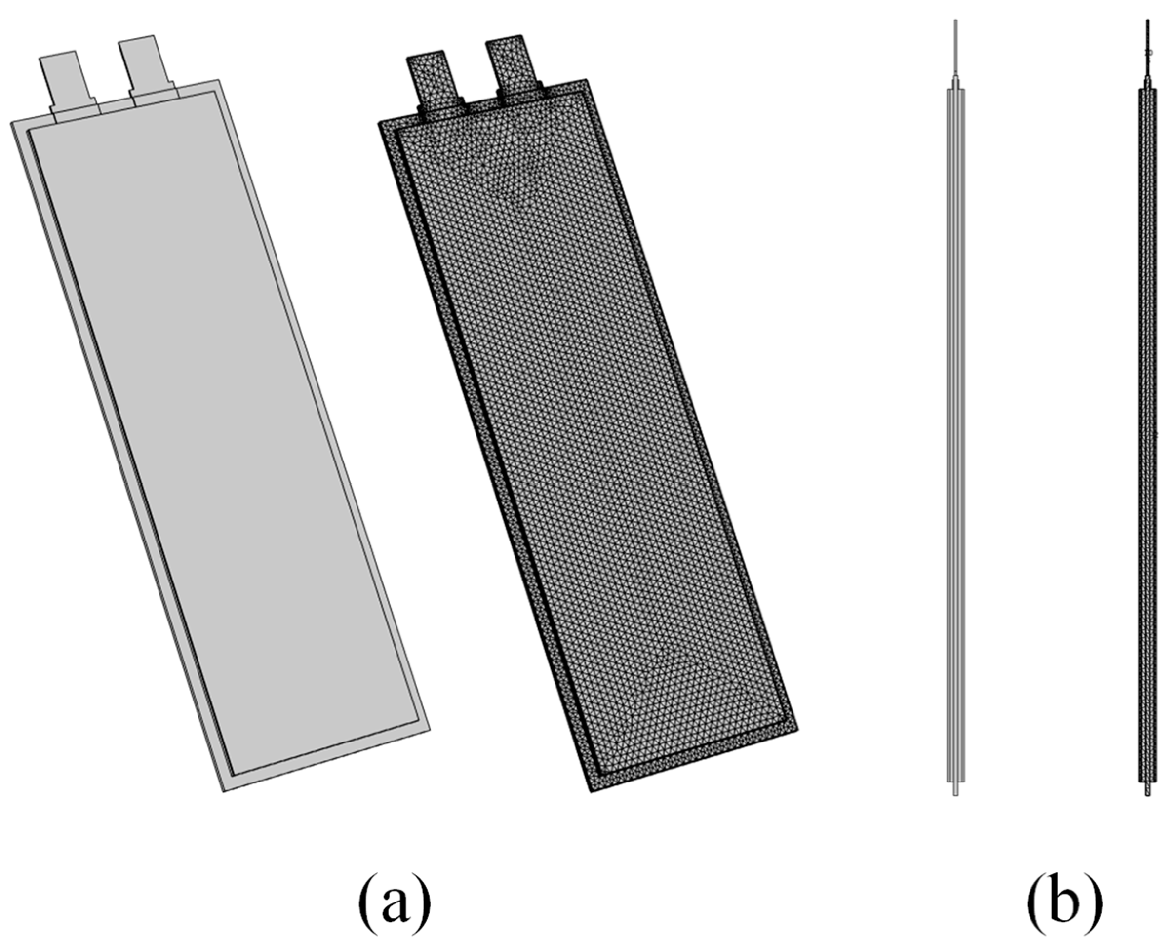
The battery thermal model is established in 3D by utilizing a heat transfer module consisting of the multilayer body and positive and negative tabs, all enclosed within a metal shell. Mesh generation is performed using the free tetrahedral method, as depicted in Figure 2. The thermal model simplifies the battery body’s laminated structure, treating it as a unified, anisotropic material with thermal conductivity. Additionally, the model incorporates the battery’s hard case, which facilitates heat transfer to the surrounding environment.
In this model, the governing equation is the energy conservation equation, as shown in Equation (1):
( ρ b a t C p , b a t T b a t ) t = 1 x x ( λ x x T b a t x ) + 1 y y ( λ y y T b a t y ) + 1 z z ( λ z z T b a t z ) + Q g e n
where Qgen represents the electrochemical enthalpy of the battery. Previous studies have suggested that Qgen includes both reversible heat Qrev and irreversible heat Qirrev. The variable Qirrev is further divided into ohmic heat Qohm and polarization heat Qpol. Equations (2)–(5) can be used to determine Qrev, Qohm, and Qpol, accordingly.
Q g e n = Q r v + Q i r r v = Q r e v + Q o h m + Q p o l
Q r e v = A j l o c , i T b a t U r e f , i T b a t
Q o h m   = σ e , i e f f 2 R g T b a t   F ( t + 1 ) ( d ln f d ln c e + 1 ) ( ln c e ) φ e , i + σ e , i e f f ( φ e , i ) 2 + σ s , i e f f ( φ s , i ) 2
Q p o l = A s , j j l o c , i η i
Qrev arises from the entropy change occurring in the electrode’s active materials during the Li+ intercalation and deintercalation process. It is absorbed during the charging process when lithium ions are intercalated into the electrode material, which requires energy input and is an endothermic process. When Li+ deintercalates from the electrode material and releases energy, Qrev is released as heat, making the battery warm up during discharge. Consequently, Qirrev is exothermic during charge/discharge, given the same SOC, and varies depending on the active materials utilized. Ions and electrons traverse the electrolyte during the charge/discharge process, causing Qohm. Qohm is generated across all of the battery multilayers, including the electrolyte, positive/negative electrode, and separator. Meanwhile, Qpol is generated due to the resistive losses and inefficiencies in the electrochemical reactions occurring at the electrodes during the charge and discharge cycles. It significantly influences the Li+ intercalation mechanism. Qpol and Qrev are exclusively produced in the electrode region.
Considering the minimal temperature difference between the battery and the environment, we opted to disregard heat radiation and focus solely on heat convection. At the thermal boundary condition, Qconv is derived as follows:
Q c o n v = 2 h d ( T s u f T a m b )
where d is the battery thickness in the direction perpendicular to the parallel electrodes, and the h value can be input by parameter scanning. It primarily encompasses the range from natural convection to forced convection.

2.2. Model Parameters

Table 3 shows the constant multilayer electrode specifications and electrochemical parameters, obtained either directly from the battery manufacturer or from the literature with necessary adjustments. Table 4 presents the temperature- and reaction kinetics-dependent parameters, including the electrode’s thermodynamic properties, the entropy thermal coefficient, dynamic variables in the electrolyte, and others [39,40].

2.3. Model Validation

The mesh independence study showed that a mesh number of 81,520 has an acceptable level of accuracy for numerical simulation. Increasing the mesh number by 100% results in nearly identical current, voltage, and temperature values, with errors of less than 0.5%.
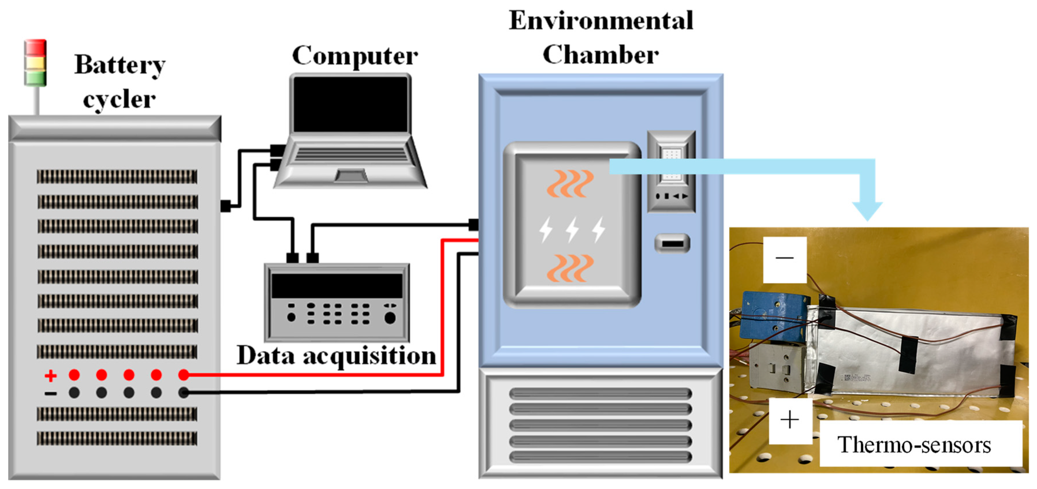
The battery’s discharge performance and temperature dynamics serve as validation criteria for the proposed model. A battery management system (BTS-5V60A, Neware Electronics Co., Ltd., Shenzhen, China) and a constant environmental chamber (GTHJ-B4170, Guangjun Technologies Inc., Suzhou, China) were employed to assess the charge-discharge behavior. Five thermo-sensors were strategically positioned at the geometric center and the four corners of the battery to monitor its temperature during discharge. The placement of these thermo-sensors is illustrated in Figure 3. Similarly, five temperature probes were situated at these exact locations in the thermal model. Experiments were conducted using three environmental chamber temperatures (273.15 K, 293.15 K, and 313.15 K). The batteries underwent charging via a constant current and voltage (CCCV) at 1C and subsequent discharge at varied constant current (CC) rates (0.5C, 1C, and 2C) for each test. Following each charge or discharge cycle, a rest period was necessary to achieve ion equilibrium in the electrolyte and allow the battery’s temperature to recover.
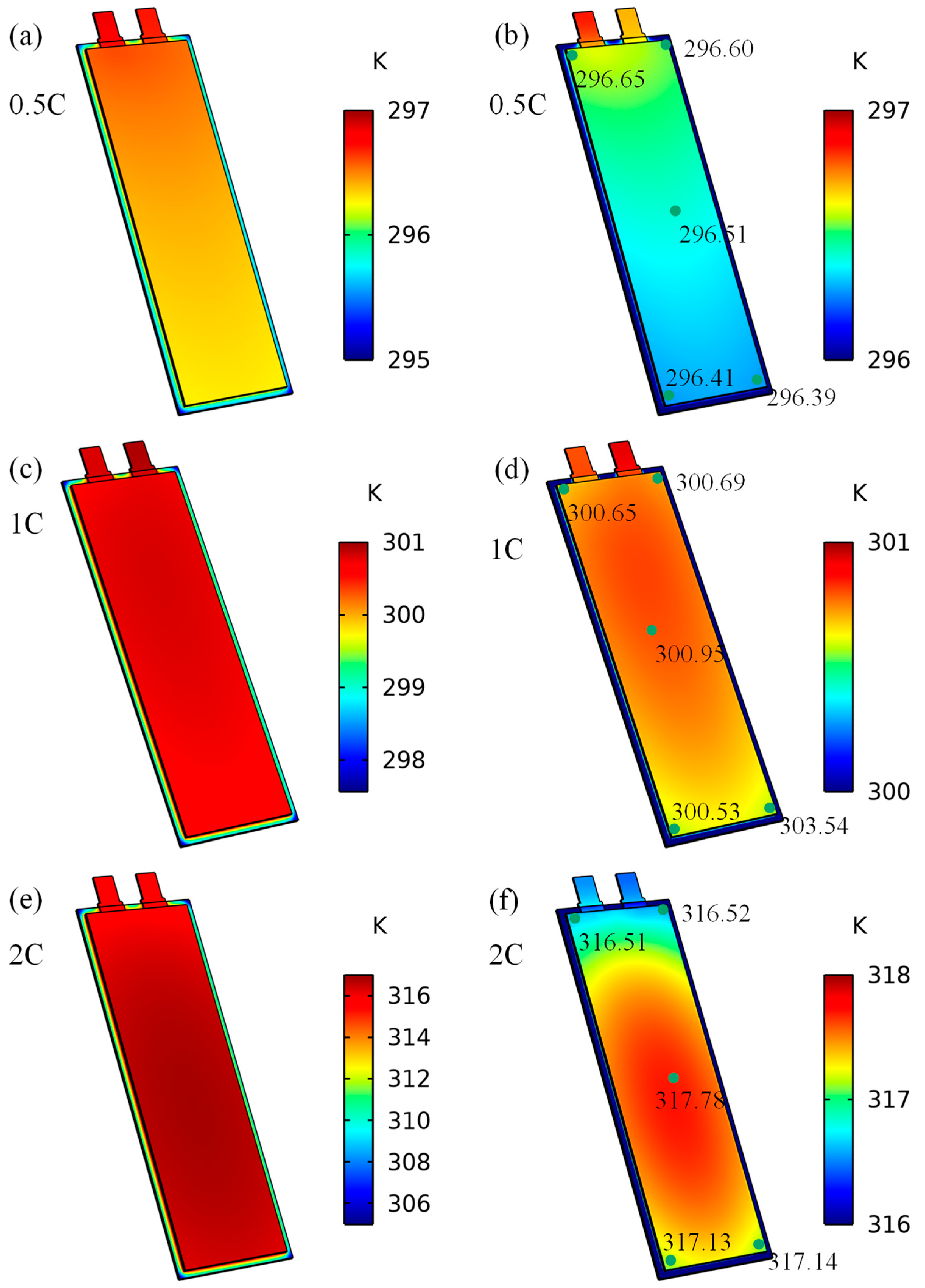
Figure 4 shows the temperature distribution at the end of the 0.5C, 1C, and 2C discharge on the battery at Tamb = 20 °C. The different colors of the battery surface indicated the temperature distribution, as shown in Figure 4a,c,e. There are contact thermal resistances between the positive/negative tabs and the conductors. Therefore, the heat generation rate of each tab is set to a constant value, respectively. The minimum temperature of the battery is on the seam since the seam does not generate heat. In order to highlight the temperature differences seen on the main body of the battery, the temperature of the seam is hidden, as shown in Figure 4b,d,e. In Figure 4b, the battery temperature has a maximum value of 296.65 K at the top of the battery, while the minimum value is 296.39 K at the bottom of the pouch battery. The temperature difference between the four corners and the center of the battery body is less than 0.26 K. In Figure 4d, the maximum temperature is transferred to the center of the battery. The maximum temperature difference on the surface of the battery is lower than 0.42 K. At 2C discharge, the temperature on the battery body exceeds that on the tabs, with the lower-middle part of the battery body having the maximum temperature. The maximum temperature difference is 1.27 K, seen in Figure 4e. The temperature difference on the battery surface steadily rises with increasing discharge rate and the highest temperature shifts from the area near the tabs to the lower-middle part of the battery. Hence, the average temperatures (Tave) of the simulation results were compared with those of the experimental results to validate the model. The results are shown in Figure 5.
When Tamb is 0 °C, after a 0.5C discharge, the simulation results in a maximum temperature rise of 6.77 K, compared to an experimental maximum temperature rise of 6.73 K. For a 1C discharge, the simulation shows a maximum temperature rise of 10.56 K, while the experimental maximum temperature rise is 11.8 K. After a 2C discharge, the simulation indicates a maximum temperature rise of 26.05 K, and the experimental maximum temperature rise is 27.75 K. The simulation’s initial voltage for a 0.5C discharge is 4.1209 V, compared to an experimental initial voltage of 4.1524 V. For a 1C discharge, the simulation’s initial voltage is 4.0664 V, and the experimental initial voltage is 4.1353 V. For a 2C discharge, the simulation’s initial voltage is 3.9937 V, and the experimental initial voltage is 4.0736 V. Similarly, at both 20 °C and 40 °C, as the ambient temperature increases, the rate of temperature rise decreases gradually, while the discharge starting voltage gradually increases. Under the same ambient temperature, as the discharge rate increases, the temperature rise gradually increases and the discharge starting voltage gradually decreases. At high discharge rates and low temperatures, there may be large differences between the simulation and experimental results, which is consistent with the findings of Li et al. [24].

3. Results and Discussion

The governing equations, boundary conditions, and mesh establishment were set using COMSOL Multiphysics® 6.1. The ambient temperatures, discharge rate, and heat transfer coefficient (h) were identified as significant factors affecting battery performance. In subsequent sections, their impact on various electrochemical characteristics is simulated and analyzed across both 1D and 3D scales.

3.1. The Impact of the Tamb on Battery Discharge Rate

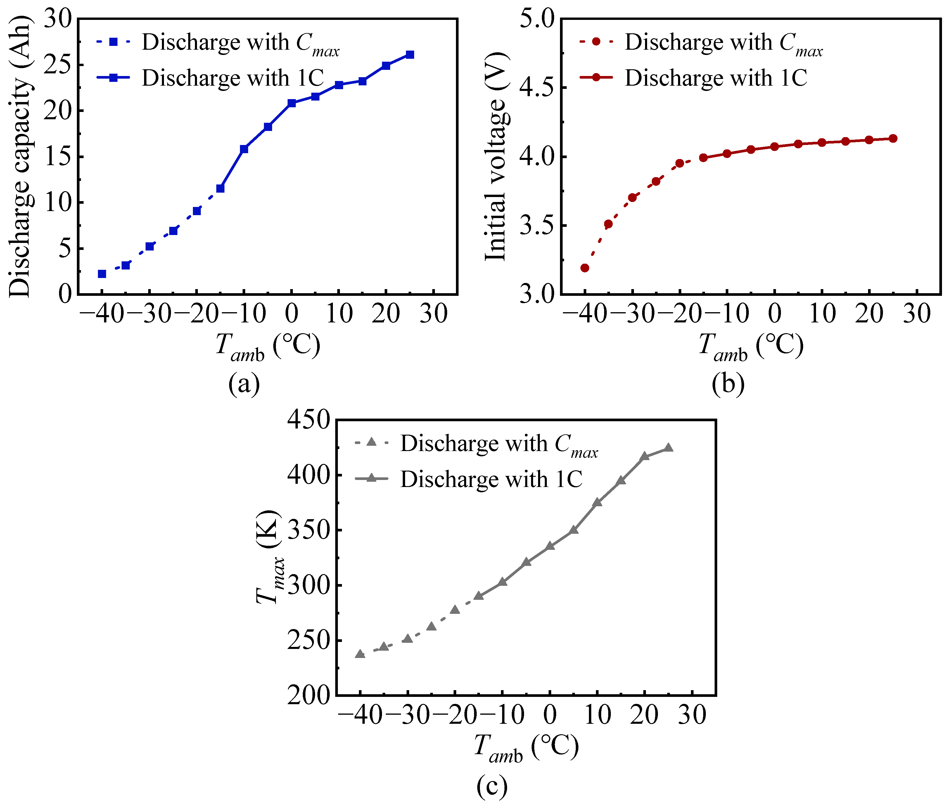
The ambient temperature plays a crucial role in determining the overall performance of the battery. Several electrochemical parameters are temperature-dependent, such as the diffusion coefficient of Li+ in both the solid and liquid phases of the positive and negative electrodes. As the ambient temperature decreases, this coefficient also decreases, resulting in the reduced mobility of lithium ions and accelerated polarization and transport resistance. These changes significantly affect the electrochemical characteristics of the battery. Therefore, simulations were conducted using an adiabatic model to study the impact of ambient temperature on the electrochemical and thermal behavior of the battery. The model inputs were parameterized using a scanning approach with different ambient temperatures (from −40 °C to 45 °C, with intervals set every 5 °C) at different discharge rates (0.1C to 5C, with intervals set every 0.1C). The results yielded the maximum discharge rate (Cmax), discharge capacity, initial voltage, and maximum temperature (Tmax) of the battery under different ambient temperatures, as shown in Table 5. Based on the discharge rates of Cmax when Tamb < 15 °C and 1C when Tamb ≥ 15 °C, the discharge capacity, initial voltage, and Tmax plots are shown in Figure 6.
At low temperatures, the electrochemical reaction rate of the power battery decreases, and the charge transfer resistance significantly increases. Compared to electrochemical ohmic resistance and SEI film impedance, the effect of temperature on the electrochemical reaction process is more pronounced. The charge transfer resistance increases exponentially as the temperature decreases [44]. Therefore, the dramatic increase in charge transfer resistance at low temperatures is the main reason for the deterioration of power battery performance. The decrease in the solid-phase diffusion coefficient of lithium ions in graphite at the negative electrode is also one of the main factors leading to the deterioration of power battery performance at low temperatures. Thus, at the same discharge rate, the battery’s discharge capacity and initial voltage both decrease significantly with decreasing ambient temperature. Simultaneously, high currents accelerate the process of lithium metal formation on the surface of the negative electrode. Additionally, temperature reduction accelerates the narrowing of the lithium plating window, restricting the energy density and charge-discharge capability, leading to a decrease in the maximum discharge rate of the battery. The above information provides the discharge rate boundaries for subsequent simulations of the overall thermal conductance across the entire temperature range.

3.2. The impact of the Heat Transfer Coefficient on Battery Temperature

In this part of the analysis, the heat transfer coefficients underwent a parametric scan under adiabatic conditions (0.01, 0.05, 0.1, and 0.5 W m−2 K−1), natural convection (1, 2, 3, 4, 5, and 10 W m−2 K−1), and forced convection (20 to 100 W m−2 K−1), as well as strong forced convection (110 to 400 W m−2 K−1). When the ambient temperature was below 25 °C, the C rate scan referred to the low-temperature discharge boundaries outlined in Section 3.1. When the Tamb was above 25 °C, the Cmax was set to 5C, based on the battery’s rated maximum input current. For ease of presentation, the relationship between Tmax and discharge rate, the heat transfer coefficient, will be illustrated in cloud plots categorized by ambient temperature. These will be depicted in Figure 7, Figure 8, Figure 9 and Figure 10.
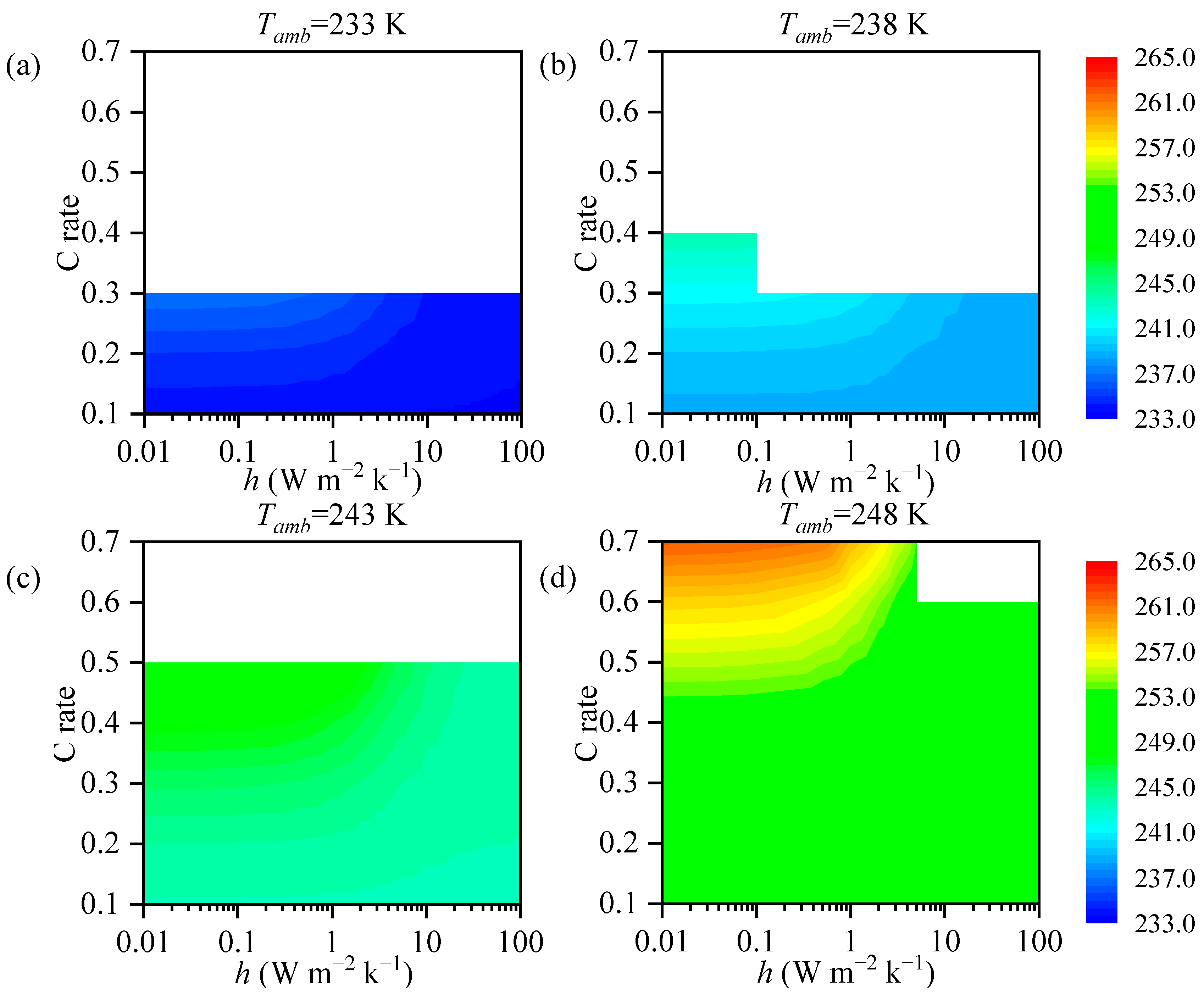
Figure 7a–d shows the Tmax of the battery at Tamb = −40, −35, −30, and −25 °C, with a heat transfer coefficient from 0.01 to 100 W m−2 K−1. To facilitate the presentation of data with low h values, the horizontal axis is logarithmically scaled. The blank areas in the figures represent invalid discharge rates. The appearance of step-like patterns is due to limited scanning precision where a decrease in the heat transfer coefficient alters the effective maximum discharge rate of the battery. Clearly, in ultra-low temperature environments, it is hard for the battery to achieve satisfactory discharge performance, even under adiabatic conditions with extremely low heat transfer coefficients. Not only does the maximum discharge rate significantly decrease, but the temperature rise during discharge is also limited, making it challenging to rely on self-heating for subsequent discharge operations. When Tamb is −40 °C, the battery temperature only increases by 3.07 K at h = 0.01 W m−2 K−1 and a C rate = 0.3. The maximum temperature occurs at Tamb = −25 °C, reaching 261.71 K. Therefore, it is nearly impossible for the battery temperature to reach above 273.15 K when the ambient temperature falls below −25 °C without an external heat source.
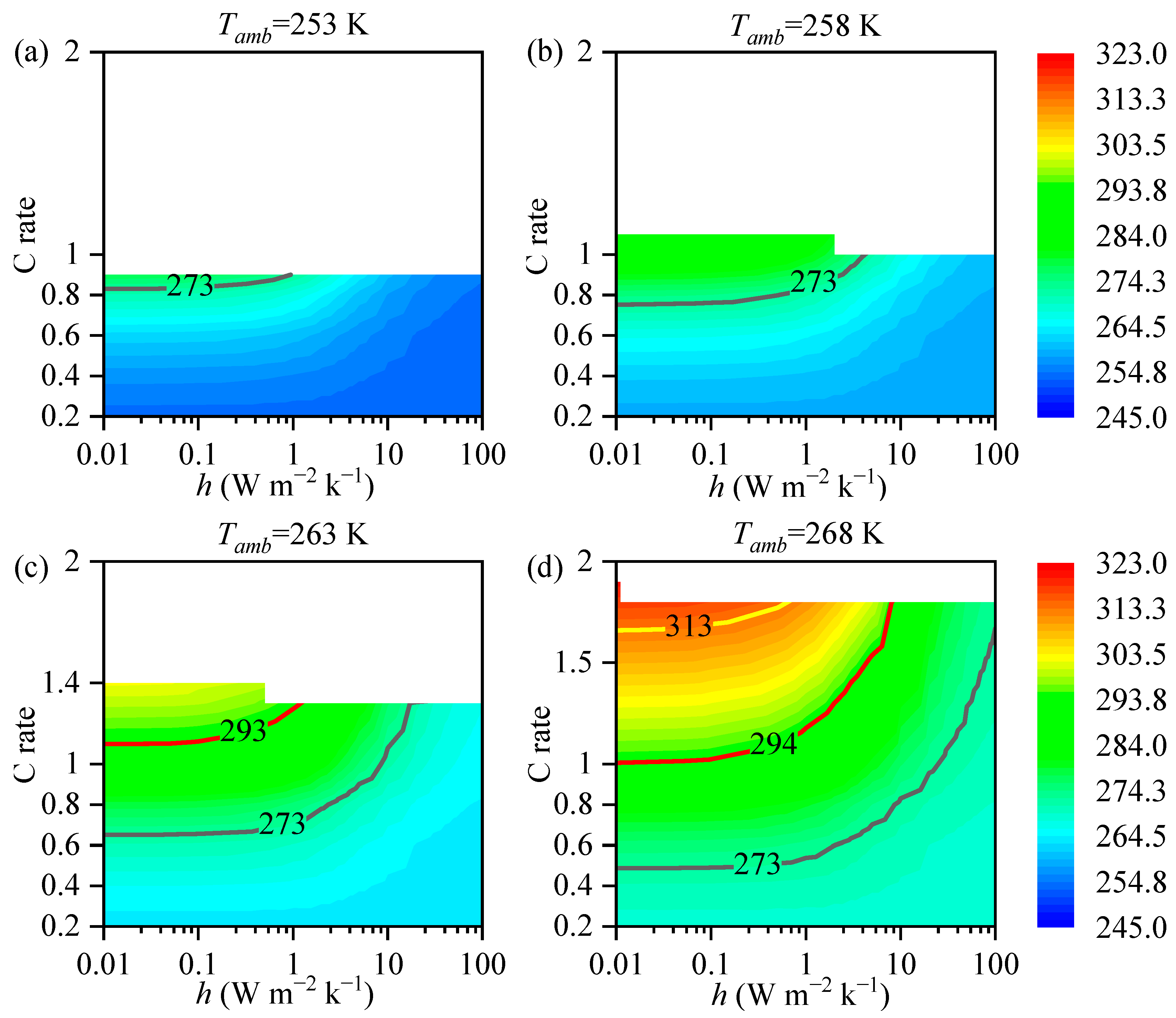
Figure 8a–d shows the Tmax of the battery at Tamb = −20, −15, −10, and −5 °C, with a heat transfer coefficient from 0.01 to 100 W m−2 K−1. The figure depicts isotherms at 273.15 K (black line), 293.15 K (red line), and 313.15 K (yellow line). It can be observed that when starting from Tamb = −20 °C, the battery temperature exceeds 273.15 K under specific heat transfer coefficients. At Tamb = −15 °C, the maximum discharge rate and the battery temperature range grow. The battery temperature can reach above 293.15 K at Tamb = −10 °C when h < 1 W m−2 K−1. Even at Tamb = −5 °C, the battery can reach temperatures above 313.15 K when h < 0.5 W m−2 K−1. Adiabatic or insulation conditions can help the battery operate within the optimal temperature window in these ambient temperature ranges. Although the battery temperature can rise above 313 K, the ambient temperature limits the initial discharge rate of the battery. Heating measures are still required to enhance the electrochemical performance of the battery.
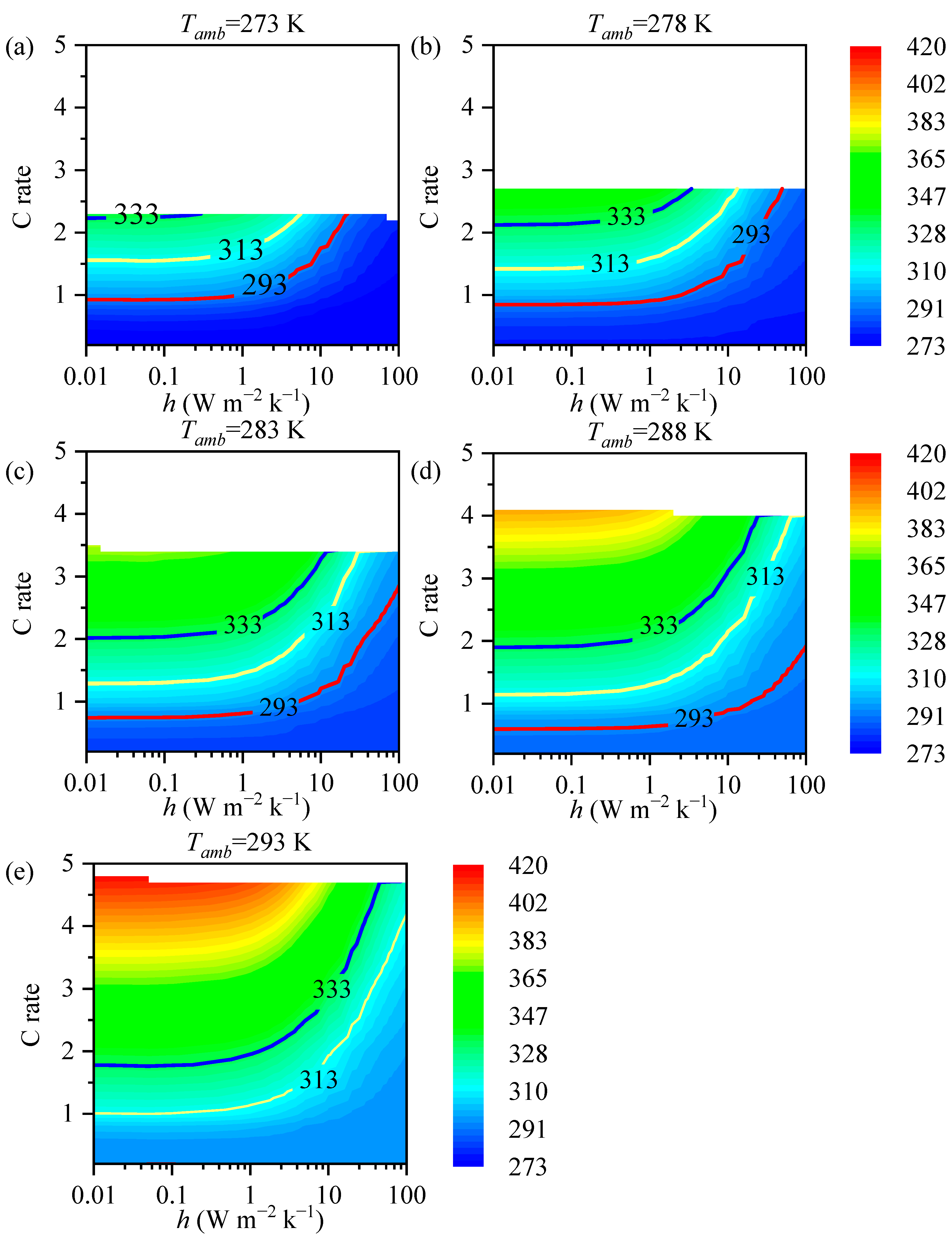
Figure 9a–e shows the Tmax of the battery at Tamb = 0, 5, 10, 15, and 20 °C with a heat transfer coefficient from 0.01 to 100 W m−2 K−1. A blue isotherm line represents the safety temperature limit of 333.15 K. In this scenario, it is necessary to increase the heat transfer coefficient to prevent the battery from overheating under high discharge rates. Natural convection and conventional forced convection (h < 50 W m−2 K−1) are sufficient to maintain the battery operating around 2C in the optimal temperature window. At Tamb = 15, 20 °C, the battery temperature will reach the runaway temperature under adiabatic conditions. This poses a danger to the battery’s operation, and strict attention should be paid to balancing the power demand with the external heat transfer coefficient.
Figure 10a–e shows the Tmax of the battery at Tamb = 25, 30, 35, 40, and 45 °C with a heat transfer coefficient from 0.01 to 400 W m−2 K−1. Above 25 °C, heat dissipation becomes the main issue. The horizontal axis of Figure 10 is linear. In this temperature range, the maximum discharge rate of the battery reaches 5C. As the temperature increases, the reaction rate of the active material in the battery core increases, and the reaction of the electrolyte becomes more intense. Without a low-temperature cooling source, the battery temperature can easily exceed the optimal and limit windows, even if the heat transfer coefficient increases to 400 W m−2 K−1 or above. The convective heat transfer coefficient can only bring the battery temperature close to the ambient temperature. Especially at temperatures exceeding 40 °C, the battery can only operate within a high temperature range. At this point, the limitation imposed on the maximum discharge rate of the battery is no longer the low temperature but rather the heat dissipation method.
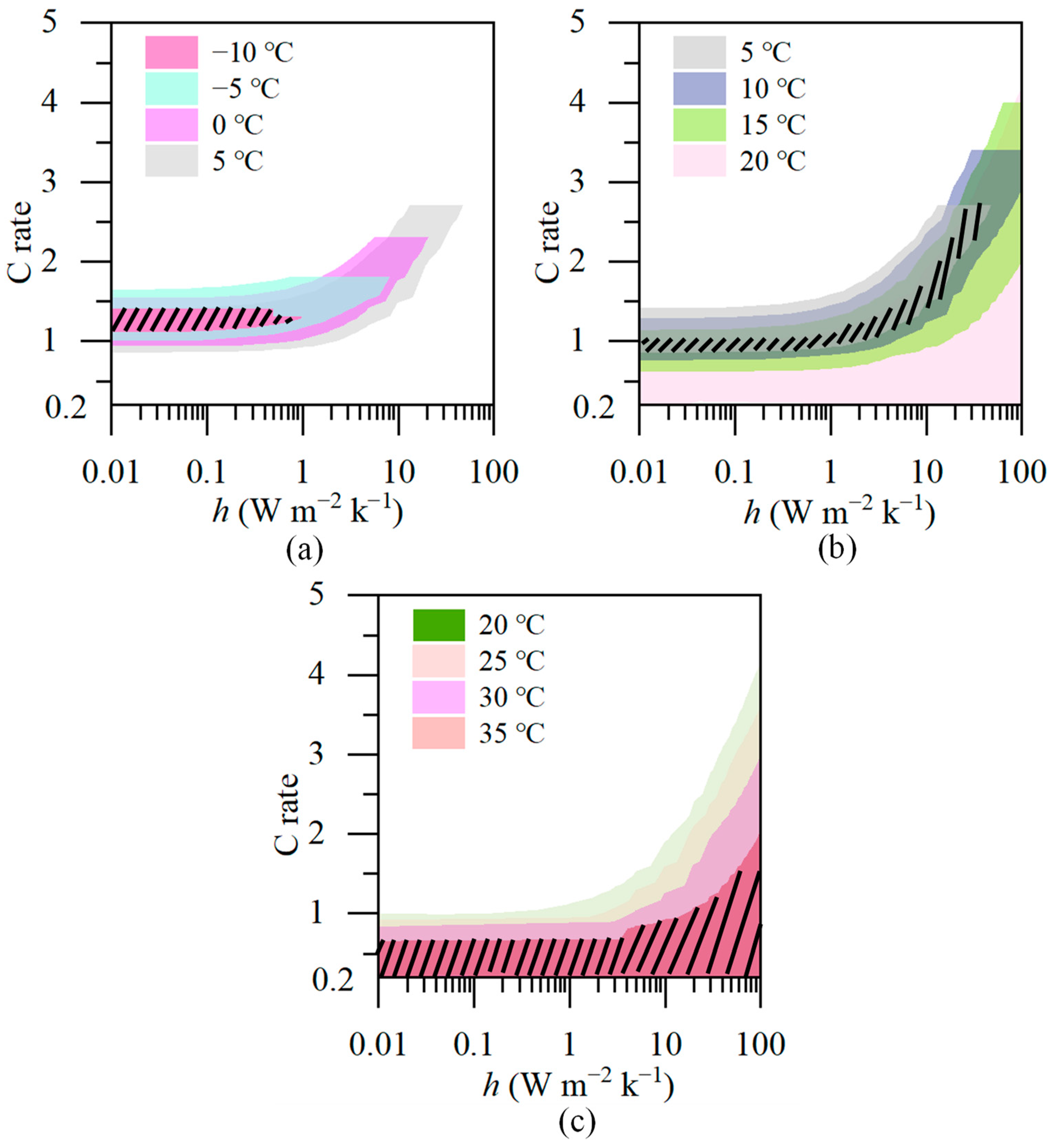
Overall, the optimal temperature range for battery operation is from −10 to 35 °C in this study. Figure 11 illustrates all operating conditions within the temperature range. The different color blocks represent different environmental temperatures, while the range of the color blocks represents the discharge rates and heat transfer coefficients that allow the battery to reach between 20 and 40 °C at the end of discharge. Because the diurnal temperature variation in most cities generally does not exceed 15 °C, the temperature range from 10 to 35 °C is divided into three segments, each spanning 15 °C, for separate analysis. The overlapping sections of the color blocks are labeled in Figure 11a–c. Within the environmental variation range of 15 °C, the battery needs to operate within the shaded area to ensure an optimal operating temperature. From −10 °C to 5 °C, the battery can operate between 1.1C and 1.4C under h < 1 W m−2 K−1. From 5 to 20 °C, the discharge rate can expand to 2.7C. The demand for h also increases to 40 W m−2 K−1. From 20 to 35 °C, the C rate depends on how significant the heat transfer coefficient is. As the Tamb increases, the shaded area gradually expands. This allows for more operating conditions where the battery can operate within the optimal temperature window.

3.3. Analysis

Based on the results from Section 3.1 and Section 3.2, we have categorized the ambient temperature and provided heat transfer recommendations to optimize the battery’s thermal performance at each temperature. The diagram is illustrated in Figure 12. Tamb values from −40 to −25 °C represent extremely cold environments, where effective discharge is nearly impossible when relying on the battery itself. This implies that specific self-heating methods based on electrochemical kinetics may fail due to insufficient battery capacity and low current. Additional heat sources are required to provide the battery with an appropriate temperature environment. Current battery heating technology includes interior heating and exterior heating. However, the activation energy of the reaction at extremely low temperatures may not meet the high current demand for internal short-circuit heating. Reliable external heating, such as liquid/phase change material heating and electric heating elements, can better adapt to extreme climates [45]. With Tamb values from −20 to −5 °C, thermal insulation can enable the battery to achieve discharge at lower rates. Applying internal heating methods can achieve a high heating rate along with low energy consumption.
When Tamb > 0 °C, the battery’s discharge capacity is restored to over 80% of its rated capacity, and its discharge capability gradually improves. At this point, natural convection can adequately meet the battery’s basic cooling needs, with h from 0.05 to 400 W m−2 K−1. A BTMS can be designed for heating integrated with cooling [46]. The switching between heating and cooling requirements can meet the heat dissipation requirements of the battery’s starting temperature and discharge limit. As the Tamb rises to 20 °C, the battery’s maximum discharge rate also increases to above 4C. Forced convection is necessary to satisfy the demand for maximum power discharge. From passive air cooling to indirect liquid-based methods, the cost and complexity of the BTMS system also need to be considered in order to meet the temperature control requirements [43].
When the Tamb exceeds 40 °C, convective cooling without a cooling source becomes less efficient. Forced cooling methods are required to decrease the battery temperature to the optimal range. Immersion cooling, where the battery is submerged in an insulating fluid, has the potential to increase heat transfer rates by up to 10,000 times compared to passive air cooling [21].
Due to the sensitivity of the battery’s internal resistance to temperature changes, especially in large pouch batteries composed of multiple layers, temperature gradients occur between layers and at different levels. This temperature gradient can lead to uneven current distribution and local heterogeneous degradation and can reduce battery life [47]. According to the battery temperature distribution under various discharge rates with different ambient temperatures, shown in Figure 4, BTMS should consider not only the working environment of the battery but also its structure. Considering the characteristics of the high-temperature area shifting from the electrodes to the battery central part as the power level increases, heat dissipation can be achieved through two-phase immersion or via composite materials for zoning management. The enhanced electrochemical performance of tab cooling can create a more uniform temperature distribution, resulting in more uniform current distributions between the battery layers.
Above all, in this article, we provide strategies for battery thermal management suitable for different temperatures, as shown in Figure 13. For environments with excessively high temperatures, designing a BTMS involves increasing the heat transfer coefficient and providing additional cooling sources. Even during storage, batteries should be monitored to prevent issues such as self-discharge and electrolyte decomposition caused by high temperatures, which can limit battery lifespan and safety. Especially in the case of battery modules located in the middle of clusters or at the end of liquid cooling systems, designing additional temperature equalization measures is essential to enhance module lifespan and electrical-thermal performance consistency. Batteries operating within their optimal temperature range can utilize BTMS with lower heat transfer coefficients to save operating costs. However, it is essential to have emergency cooling methods in place to prevent sudden thermal runaway disasters. Batteries operating in cold environments require insulation or heating to help them reach their optimal operating range. Nonetheless, attention should also be paid to thermal management during high-power conditions. In extremely low-temperature environments, lithium-ion batteries require additional active heating devices to facilitate cold starting. Considering temperature variations due to seasonal changes or power transitions, future BTMS designs need to be increasingly flexible. From heating to insulation to cooling, smart combinations of active and passive methods are necessary to ensure the widespread and safe application of lithium-ion batteries.

4. Conclusions

For this study, we developed a coupled 1D electrochemical 3D thermal model of a 26 Ah lithium-ion pouch cell. We investigated the electrical and thermal behavior of the battery under different C rates, ambient temperatures, and heat transfer coefficients. The simulation results were validated against the experimental data. Some key conclusions are as follows:
(1)
Ambient temperature significantly impacts the electrochemical and thermal performance of lithium-ion batteries. Higher discharge rates lead to increased polarization and ion transport resistance, demanding higher reaction temperatures. Consequently, the maximum discharge rate of the cell decreases at low temperatures.
(2)
The maximum temperature of the battery is correlated with the heat transfer coefficient. The required magnitude of the heat transfer coefficient varies with different ambient temperatures. At low temperatures, adiabatic conditions are required to provide thermal insulation for the battery, while at high temperatures, increasing the heat transfer coefficient is necessary for effective heat dissipation from the battery.
(3)
Different heat transfer coefficients correspond to various thermal management strategies. Designing a BTMS with tailored heat transfer coefficients for typical environmental conditions and discharge rates can enhance battery performance accurately and efficiently. Additionally, taking into account the time or power dependence of heat generation based on battery geometry is crucial. These research findings offer a reference for designing future lithium-ion BTMS.

Author Contributions

Conceptualization, X.J.; Methodology, K.L.; Software, K.L. and C.S.; Validation, K.L.; Formal analysis, C.S.; Investigation, K.L.; Resources, B.W.; Data curation, K.L. and Y.C.; Writing—original draft, K.L.; Writing—review & editing, X.J. and C.X.; Supervision, C.X.; Project administration, S.W.; Funding acquisition, M.Z. and X.J. All authors have read and agreed to the published version of the manuscript.

Funding

This research was funded by the Science and Technology Project of the State Grid Corporation of China (Development and Application of Immersion Liquid Cooling Technology for Battery Energy Storage System, 4000-202420082A-1-1-ZN).

Data Availability Statement

The data presented in this study are available on request from the corresponding author due to privacy.

Conflicts of Interest

The authors declare that they have no known competing financial interests or personal relationships that could have appeared to influence the work reported in this paper.

Nomenclature

Aspecific surface area (m−1)
cLi+ concentration (mol m−3)
Cp,batvolumetric heat capacity (J m−3 K−1)
CCCVconstant current constant voltage
Cmaxmaximum discharge rate
dbattery thickness (m)
Ddiffusion coefficient (m2 s−1)
fthermodynamic factor
Ffaraday constant (C mol−1)
Grelevant parameters of porous properties
hheat convection coefficient (W m−2 K−1)
iappexternal current (A)
j0exchange current density (A m−2)
jloclocal current density (A m−2)
jLitransfer current density (A m−3)
kreaction rate coefficient (m−1 s−1)
Llength of each layer (μm)
qheat generation of each part (W m−3)
Qgenrate of total heat generation (W m−3)
rdistance to the center of the particle (μm)
Ractive particle radius (μm)
Rgideal gas constant (J mol−1 K−1)
SOCstate of charge
t+transference number of lithium ion
Ttemperature (K)
Uelectrode potential (V)
Vterminal voltage (V)
αtransfer coefficient
γcorrection coefficient
εvolume fraction
ηoverpotential (V)
λthermal conductivity (W m−1 K−1)
ρdensity (kg m−3)
σconductivity (S m−1)
φelectric potential (V)
aanode
aveaverage
polpolarized
ambambient
batbattery
cacathode
convconvective heat
eelectrolyte phase
effeffective parameter
eqequilibrium
irrevirreversible
maxmaximum
nnegative electrode
ohmohmic
ppositive electrode
refreference value
revreversible
ssolid phase
seseparator
surfsurface

References

  1. Tran, M.; Mathew, M.; Janhunen, S.; Panchal, S.; Raahemifar, K.; Fraser, R.; Fowler, M. A comprehensive equivalent circuit model for lithium-ion batteries, incorporating the effects of state of health, state of charge, and temperature on model parameters. J. Energy Storage 2021, 43, 103252. [Google Scholar] [CrossRef]
  2. Suresh Patil, M.; Seo, J.; Lee, M. A novel dielectric fluid immersion cooling technology for Li-ion battery thermal management. Energy Convers. Manag. 2021, 229, 113715. [Google Scholar] [CrossRef]
  3. Zhou, G.; Li, Y.; Liu, Y.; Zhang, Q.; Wei, Z.; Li, S.; Yang, S.; Yuan, S.; Fan, T.; Huang, Q. Preparation of a novel environmental-friendly lithium-ion battery fire suppression microcapsule and its fire extinguishing mechanism in coordination with ABC dry powder. J. Clean. Prod. 2024, 448, 141438. [Google Scholar] [CrossRef]
  4. Hassan, M.K.; Hameed, N.; Hossain, M.D.; Hasnat, M.R.; Douglas, G.; Pathirana, S.; Rahnamayiezekavat, P.; Saha, S. Fire Incidents, Trends, and Risk Mitigation Framework of Electrical Vehicle Cars in Australia. Fire 2023, 6, 325. [Google Scholar] [CrossRef]
  5. Li, X.; Zhao, J.; Duan, J.; Panchal, S.; Yuan, J.; Fraser, R.; Fowler, M.; Chen, M. Simulation of cooling plate effect on a battery module with different channel arrangement. J. Energy Storage 2022, 49, 104113. [Google Scholar] [CrossRef]
  6. Vashisht, S.; Rakshit, D.; Panchal, S.; Fowler, M.; Fraser, R. Thermal behaviour of Li-ion battery: An improved electrothermal model considering the effects of depth of discharge and temperature. J. Energy Storage 2023, 70, 107797. [Google Scholar] [CrossRef]
  7. Chen, Z.; Qin, Y.; Dong, Z.; Zheng, J.; Liu, Y. Numerical study on the heat generation and thermal control of lithium-ion battery. Appl. Therm. Eng. 2023, 221, 119852. [Google Scholar] [CrossRef]
  8. He, T.; Zhang, T.; Wang, Z.; Cai, Q. A comprehensive numerical study on electrochemical-thermal models of a cylindrical lithium-ion battery during discharge process. Appl. Energy 2022, 313, 118797. [Google Scholar] [CrossRef]
  9. Sun, Z.; Fan, R.; Zheng, N. Thermal management of a simulated battery with the compound use of phase change material and fins: Experimental and numerical investigations. Int. J. Therm. Sci. 2021, 165, 106945. [Google Scholar] [CrossRef]
  10. Rodrigues, M.T.F.; Son, S.; Colclasure, A.M.; Shkrob, I.A.; Trask, S.E.; Bloom, I.D.; Abraham, D.P. How Fast Can a Li-Ion Battery Be Charged? Determination of Limiting Fast Charging Conditions. ACS Appl. Energy Mater. 2021, 4, 1063–1068. [Google Scholar] [CrossRef]
  11. Ruan, H.; Sun, B.; Zhang, W.; Su, X.; He, X. Quantitative Analysis of Performance Decrease and Fast-Charging Limitation for Lithium-Ion Batteries at Low Temperature Based on the Electrochemical Model. IEEE Trans. Intell. Transp. Syst. 2021, 22, 640–650. [Google Scholar] [CrossRef]
  12. Zhang, C.; Zhao, T.S.; Xu, Q.; An, L.; Zhao, G. Effects of operating temperature on the performance of vanadium redox flow batteries. Appl. Energy 2015, 155, 349–353. [Google Scholar] [CrossRef]
  13. Fraser, R. Mathematical Heat Transfer Modeling and Experimental Validation of Lithium-Ion Battery Considering: Tab and Surface Temperature, Separator, Electrolyte Resistance, Anode-Cathode Irreversible and Reversible Heat. Batteries 2020, 6, 61. [Google Scholar] [CrossRef]
  14. Yue, Q.L.; He, C.X.; Wu, M.C.; Zhao, T.S. Advances in thermal management systems for next-generation power batteries. Int. J. Heat. Mass. Transf. 2021, 181, 121853. [Google Scholar] [CrossRef]
  15. Thakur, A.K.; Prabakaran, R.; Elkadeem, M.R.; Sharshir, S.W.; Arıcı, M.; Wang, C.; Zhao, W.; Hwang, J.-Y.; Saidur, R. A state of art review and future viewpoint on advance cooling techniques for Lithium–ion battery system of electric vehicles. J. Energy Storage 2020, 32, 101771. [Google Scholar] [CrossRef]
  16. Tete, P.R.; Gupta, M.M.; Joshi, S.S. Developments in battery thermal management systems for electric vehicles: A technical review. J. Energy Storage 2021, 35, 102255. [Google Scholar] [CrossRef]
  17. Zhu, X.; Sun, Z.; Wang, Z.; Wang, H.; Lin, N.; Shan, C. Thermal runaway in commercial lithium-ion cells underover heating condition and the safety assessment method Effects of SoCs, cathode materials and packaging forms. J. Energy Storage 2023, 68, 107768. [Google Scholar] [CrossRef]
  18. Sharma, D.K.; Prabhakar, A. A review on air cooled and air centric hybrid thermal management techniques for Li-ion battery packs in electric vehicles. J. Energy Storage 2021, 41, 102885. [Google Scholar] [CrossRef]
  19. Yu, Z.; Zhang, J.; Pan, W. A review of battery thermal management systems about heat pipe and phase change materials. J. Energy Storage 2023, 62, 106827. [Google Scholar] [CrossRef]
  20. Lee, S.; Han, U.; Lee, H. Development of a hybrid battery thermal management system coupled with phase change material under fast charging conditions. Energy Convers. Manag. 2022, 268, 116015. [Google Scholar] [CrossRef]
  21. Roe, C.; Feng, X.; White, G.; Li, R.; Wang, H.; Rui, X.; Li, C.; Zhang, F.; Null, V.; Parkes, M.; et al. Immersion cooling for lithium-ion batteriesA review. J. Power Sources 2022, 525, 231094. [Google Scholar] [CrossRef]
  22. Xiao, M.; Choe, S.Y. Dynamic modeling and analysis of a pouch type LiMn2O4/Carbon high power Li-polymer battery based on electrochemical-thermal principles. J. Power Sources 2012, 218, 357–367. [Google Scholar] [CrossRef]
  23. Baveja, R.; Bhattacharya, J.; Panchal, S.; Fraser, R.; Fowler, M. Predicting temperature distribution of passively balanced battery module under realistic driving conditions through coupled equivalent circuit method and lumped heat dissipation method. J. Energy Storage 2023, 70, 107967. [Google Scholar] [CrossRef]
  24. Li, H.; Saini, A.; Liu, C.; Yang, J.; Wang, Y.; Yang, T.; Pand, C.; Chen, L.; Jiang, H. Electrochemical and thermal characteristics of prismatic lithium-ion battery based on a three-dimensional electrochemical-thermal coupled model. J. Energy Storage 2021, 42, 102976. [Google Scholar] [CrossRef]
  25. Guo, M.; White, R.E. Thermal Model for Lithium Ion Battery Pack with Mixed Parallel and Series Configuration. J. Electrochem. Soc. 2011, 158, A1166–A1176. [Google Scholar] [CrossRef]
  26. Celik, A.; Coban, H.; Göcmen, S.; Ezan, M.A.; Gören, A.; Erek, A. Passive thermal management of the lithium-ion battery unit for a solar racing car. Int. J. Energy Res. 2019, 43, 3681–3691. [Google Scholar] [CrossRef]
  27. He, C.X.; Yue, Q.L.; Wu, M.C.; Chen, Q.; Zhao, T.S. A 3D electrochemical-thermal coupled model for electrochemical and thermal analysis of pouch-type lithium-ion batteries. Int. J. Heat Mass Transf. 2021, 181, 121855. [Google Scholar] [CrossRef]
  28. Lyu, P.; Huo, Y.; Qu, Z.; Rao, Z. Investigation on the thermal behavior of Ni-rich NMC lithium ion battery for energy storage. Appl. Therm. Eng. 2020, 166, 114749. [Google Scholar] [CrossRef]
  29. Liang, J.; Gan, Y.; Song, W.; Tan, M.; Li, Y. Thermal–Electrochemical simulation of electrochemical characteristics and temperature difference for a battery module under two-stage fast charging. J. Energy Storage 2020, 29, 101307. [Google Scholar] [CrossRef]
  30. Perez Estevez, M.A.; Calligaro, S.; Bottesi, O.; Caligiuri, C.; Renzi, M. An electro-thermal model and its electrical parameters estimation procedure in a lithium-ion battery cell. Energy 2021, 234, 121296. [Google Scholar] [CrossRef]
  31. Jokar, A.; Rajabloo, B.; Désilets, M.; Lacroix, M. Review of simplified Pseudo-two-Dimensional models of lithium-ion batteries. J. Power Sources 2016, 327, 44–55. [Google Scholar] [CrossRef]
  32. Xu, J.; Gao, P.; Qiu, X.; Li, H.; Zhuang, Q.; Wu, K.; Zheng, H. Kinetic and transport characteristics of LiNi0.8Co0.1Mn0.1O2 lithium-ion batteries. Solid State Ion 2023, 395, 116216. [Google Scholar]
  33. Newman, J.; Thielemann, W. Porous-Electrode Theory with Battery Applications. AlChE J. 1975, 21, 25–41. [Google Scholar] [CrossRef]
  34. Schweiss, R. Validation of 1D porous electrode theory using steady-State measurements of flooded electrodes at variable electrolyte compositions. Chem. Eng. Sci. 2020, 226, 115841. [Google Scholar] [CrossRef]
  35. Liu, K.; Gao, Y.; Zhu, C.; Li, K.; Fei, M.; Peng, C.; Zhang, X.; Han, Q.-L. Electrochemical modeling and parameterization towards control-oriented management of lithium-ion batteries. Control Eng. Pract. 2022, 124, 105176. [Google Scholar] [CrossRef]
  36. Zhang, X.; Li, P.; Wang, K.; Zhang, H.; Huang, H. Numerical investigation on the elastoplastic behavior and fatigue life of the current collector of lithium-ion batteries based on the electrochemical-thermal-mechanical coupling model. J. Energy Storage 2023, 68, 107792. [Google Scholar] [CrossRef]
  37. Alkhedher, M.; Al Tahhan, A.B.; Yousaf, J.; Ghazal, M.; Shahbazian-Yassar, R.; Ramadan, M. Electrochemical and thermal modeling of lithium-ion batteries: A review of coupled approaches for improved thermal performance and safety lithium-ion batteries. J. Energy Storage 2024, 86, 111172. [Google Scholar] [CrossRef]
  38. Dao, T.; Vyasarayani, C.P.; McPhee, J. Simplification and order reduction of lithium-ion battery model based on porous-electrode theory. J. Power Sources 2012, 198, 329–337. [Google Scholar] [CrossRef]
  39. Ren, D.; Smith, K.; Guo, D.; Han, X.; Feng, X.; Lu, L.; Ouyang, M.; Li, J. Investigation of Lithium Plating-Stripping Process in Li-Ion Batteries at Low Temperature Using an Electrochemical Model. J. Electrochem. Soc. 2018, 165, A2167–A2178. [Google Scholar] [CrossRef]
  40. Han, X.; Ouyang, M.; Lu, L.; Li, J. Simplification of physics-based electrochemical model for lithium ion battery on electric vehicle. Part I: Diffusion simplification and single particle model. J. Power Sources 2015, 278, 802–813. [Google Scholar]
  41. Li, J.; Cheng, Y.; Ai, L.; Jia, M.; Du, S.; Yin, B.; Woo, S.; Zhang, H. 3D simulation on the internal distributed properties of lithium-ion battery with planar tabbed configuration. J. Power Sources 2015, 293, 993–1005. [Google Scholar] [CrossRef]
  42. Xu, W.; Hu, P. Numerical study on thermal behavior and a liquid cooling strategy for lithium-ion battery. Int. J. Energy Res. 2020, 44, 7645–7659. [Google Scholar] [CrossRef]
  43. Liu, Z.; Xu, G.; Xia, Y.; Tian, S. Numerical study of thermal management of pouch lithium-ion battery based on composite liquid-cooled phase change materials with honeycomb structure. J. Energy Storage 2023, 70, 108001. [Google Scholar] [CrossRef]
  44. Ouyang, T.; Ye, J.; Xu, P.; Wang, C.; Xu, E. Estimation of state-of-charge and state-of-health for lithium-ion battery based on improved firefly optimized particle filter. J. Energy Storage 2023, 68, 107733. [Google Scholar] [CrossRef]
  45. Wu, S.; Xiong, R.; Li, H.; Nian, V.; Ma, S. The state of the art on preheating lithium-ion batteries in cold weather. J. Energy Storage 2020, 27, 101059. [Google Scholar] [CrossRef]
  46. He, F.; Li, X.; Zhang, G.; Zhong, G.; He, J. Experimental investigation of thermal management system for lithium ion batteries module with coupling effect by heat sheets and phase change materials. Int. J. Energy Res. 2018, 42, 3279–3288. [Google Scholar] [CrossRef]
  47. Hunt, I.A.; Zhao, Y.; Patel, Y.; Offer, G.J. Surface Cooling Causes Accelerated Degradation Compared to Tab Cooling for Lithium-Ion Pouch Cells. J. Electrochem. Soc. 2016, 163, A1846–A1852. [Google Scholar] [CrossRef]
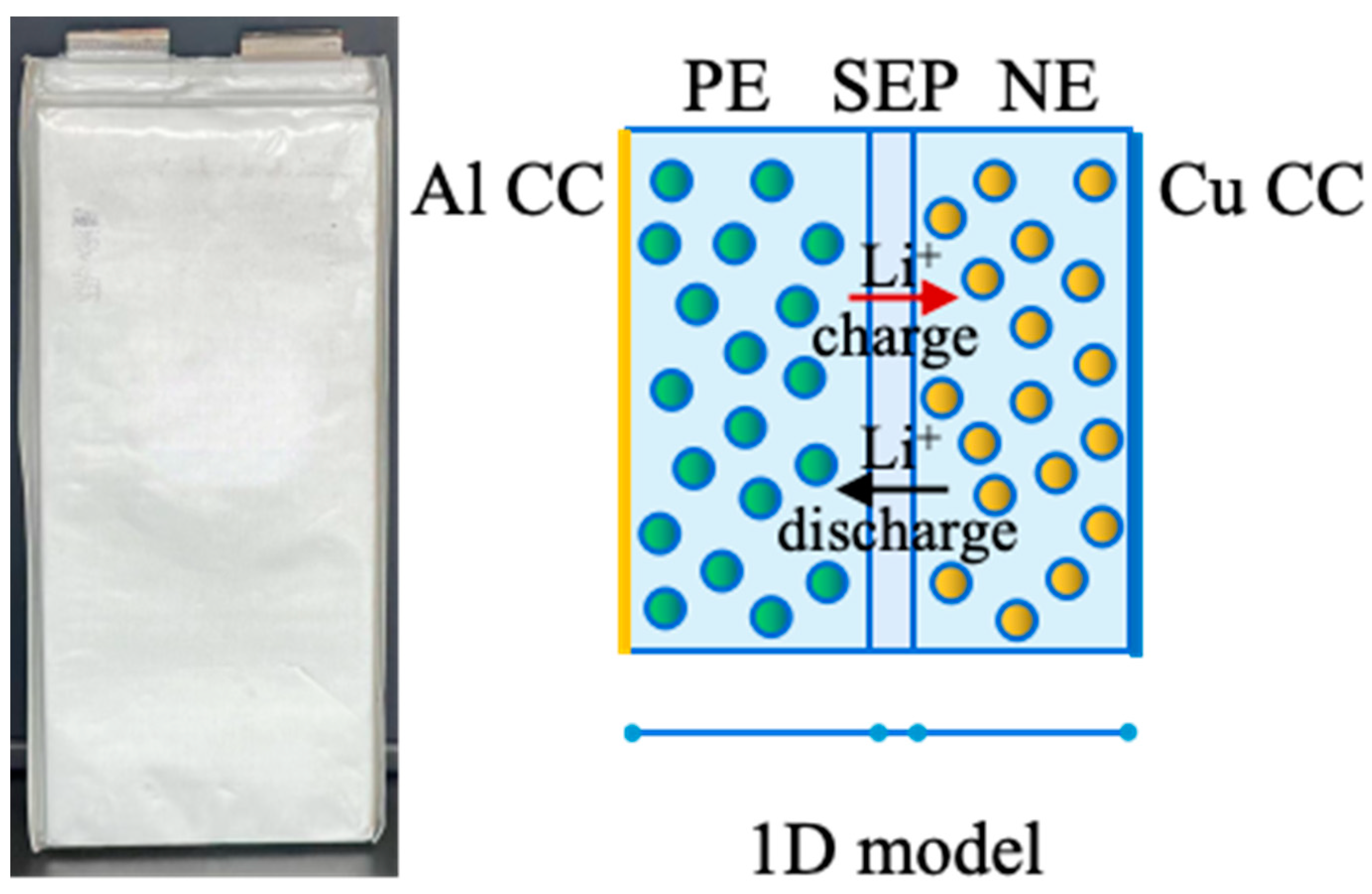
Figure 1. The pouch battery and the 1D electrochemical model.
Energies 17 02319 g001
Figure 2. Schematics of the 3D model and the corresponding grid used in the study: (a) 3D view; (b) side plane view.
Energies 17 02319 g002
Figure 3. Schematic diagram of the experimental setup and the thermos-sensors on the sample battery.
Energies 17 02319 g003
Figure 4. Temperature counters of the battery at the end of 1C of discharge, when Tamb = 20 °C: (a,c,e) body temperature; (b,d,f) body temperature without the seam.
Energies 17 02319 g004
Figure 5. Validation of the modeling and experimental results for the battery Tave (a,c,e) and the battery voltage (b,d,f).
Energies 17 02319 g005
Figure 6. Effect of different Tamb values on battery parameters. (a) Discharge capacity; (b) initial voltage; (c) Tmax.
Energies 17 02319 g006
Figure 7. The Tmax of the battery with a heat transfer coefficient from 0.01 to 100 W m−2 K−1 at Tamb of (a) −40 °C, (b) −35 °C, (c) −30 °C, and (d) −25 °C.
Energies 17 02319 g007
Figure 8. The Tmax of the battery with a heat transfer coefficient from 0.01 to 100 W m−2 K−1 at Tamb of (a) −20 °C, (b) −15 °C, (c) −10 °C, and (d) −5 °C.
Energies 17 02319 g008
Figure 9. The Tmax of the battery with a heat transfer coefficient from 0.01 to 100 W m−2 K−1 at Tamb of (a) 0 °C, (b) 5 °C, (c) 10 °C, (d) 15 °C, and (e) 20 °C.
Energies 17 02319 g009
Figure 10. The Tmax of the battery with a heat transfer coefficient from 0.01 to 400 W m−2 K−1 at Tamb of (a) 25 °C, (b) 30 °C, (c) 35 °C, (d) 40 °C, and (e) 45 °C.
Energies 17 02319 g010
Figure 11. Layered diagram of the optimal temperature range at (a) Tamb = −10 to 5 °C, (b) Tamb = 5 to 20 °C, (c) Tamb = 20 to 35 °C.
Energies 17 02319 g011
Figure 12. The diagram shows the relationship between ambient temperature, maximum C rate, and the heat transfer coefficient where Tamb = −40 to 45 °C.
Energies 17 02319 g012
Figure 13. Thermal management strategies for lithium-ion batteries across the entire temperature range.
Energies 17 02319 g013
Table 1. Basic specifications of the battery [31,32].
PropertySpecification
Nominal voltage3.6 V
Maximum charge voltage4.2 V
Maximum discharge rate5C
Charge cut-off current500 mA
Discharge cut-off voltage2.7 V
Electrode chemistryNMC/graphite
Electrolyte chemistryLiPF6 and 3:7 EC:EMC
Size342 × 118 × 8 mm3
Table 2. Governing equations and boundary conditions [35,36,37,38].
Electrochemical ModelGoverning EquationBoundary and Continuity Conditions
Mass conservation in solid phase c s , i t = D s , i r 2 r ( r 2 2 c s , i r ) c s , i r | r = 0 = 0
D s , i 2 c s , i r | r = R s , i = j L i A s , i F
Mass conservation in liquid phase ε e , i c e t + ( D e , i e f f c e ) A s , i j l o c , i F ( 1 t + ) = 0 c e x | x = 0 = c e x | x = L p + L s e + L n = 0
c e x | x = L p = c e x | x = L p +
c e x | x = ( L p + L s e ) - = c e x | x = ( L p + L s e ) +
Charge conservation in solid phase ( σ s , i e f f φ s , i ) = A s , i j l o c , i σ s , i e f f   φ s , i x | x = 0 = i a p p σ s , i e f f   φ s , i x | x = L = i a p p
φ s , i | x = L = 0
Charge conservation in liquid phase ( σ s , i e f f φ e + 2 R g T b a t σ e , i e f f F ( t + 1 ) ( 1 + ln f ln c e ) ln c e ) + A s , i j l o c , i = 0 φ e x | x = 0 = φ e x | x = L = 0
Electrochemical dynamics j l o c , i = j 0 , i { exp [ a a η i F R g T b a t ] exp [ a a η i F R g T b a t ] }
η i = φ s , i φ e , i U e q , i
j 0 , i = F k s , i c e a a ( c s , max , i c s , s u r f , i ) a a c s , s u r f , i a a
Table 3. Parameters for the coupled model.
ParametersValuesRef.
Length, Li (μm)55/10/65 for PE/SEP/NE[41]
Liquid phase volume fraction, εe,i0.30/0.37/0.30 for PE/SEP/NE[36]
Solid phase volume fraction, εs,i0.48/0.6/0.528 for PE/SEP/NE[36]
Additive volume fraction, εelse,i (μm)0.19/0.068 for PE/NE[36]
Solid active particles radius, Rs,I (μm)2.7/1.5 for PE/NE[34]
Maximum concentration of Li+ in active material, Cs,max.i (mol m−3)31,507/38,021 for PE/NE[34]
Reaction rate coefficient, ks,07 × 10−12[41]
Initial electrolyte concentration, ce,0 (mol m−3)1200[34]
Specific surface area, As,I. (m−1)s,i/Rs,i
Transference number of Li+, t+0.363[41]
Transfer coefficient, ai0.5[42]
Ideal gas constant, Rg (J mol−1 K−1)8.314[42]
Reference temperature, Tref (K)293.15
Volumetric heat capacity, Cpbat (J m−3 K−1)960.65[43]
Faraday constant, F (C mol−1)96,487
Battery density, rbat (kg m−3)2571.6[43]
Thermal conductivity, λx,y,z (W m−2 K−1)36.2/36.2/1.204 for x/y/z direction[43]
Table 4. The thermodynamic and kinetic dynamic parameters utilized in this model [39,40].
ParametersEquations
Solid diffusion coefficient of electrode kinetics D 1 , c a = 5 × 10 14 exp ( 25000 R g ( 1 T r e f 1 T b a t   ) )
D 1 , a = 3.9 × 10 14 exp ( 42000 R g ( 1 T r e f 1 T b a t ) )
Reaction rate k s , p = k s , 0 exp ( 40000 R g ( 1 T r e f 1 T b a t   ) )
k s , n = k s , 0 exp ( 20000 R g ( 1 T r f f 1 T b a t ) )
Electrode thermodynamic properties of equilibrium potential U e q , i = U r e f , i + ( T b a t T r e f ) d U r e f , i d T
Entropy changes of electrodes d U r e f , p d T = ( 21.624 S O C p 8 + 81.462 S O C p 7 127.9796 S O C p 6 + 111.39549 S O C p 5 59.77425 S O C p 4 + 19.7009 S O C p 3 3.4301 S O C p 2 + 0.2762 S O C p 0.1008 ) × 10 3
Electrolyte diffusion coefficients D e , i = 1 × 10 4 × 10 4.43 54.0 T b a t 229.0 0.05 c 2.2 × 10 4 c
Dynamic variables in electrolyte related to the Li+ transport v = 0.601 0.24 10 3 C + 0.982 ( 1 0.0052 ( T 294.0 ) 10 9 C 3 )
Thermodynamic factor k 2 = 1.12 × 10 4 ( 8.2488 + 0.053248 T 2.9871 × 10 5 T 2 + 0.26235 C 9.3063 × 10 3 C T + 8.069 × 10 6 C T 2 + 0.22002 C 2 1.765 × 10 4 C 2 T )
Electrolyte conductivity f = ( 0.2141 + 0.001159 c e 7.292 × 10 7 c e 2 + 1.136 × 10 7 c e 3 3.61 × 10 13 c e 3 ) exp ( 1000 R g ( 1 T r e f   1 T b a t   ) )
Table 5. The discharge capacity, initial voltage, and Cmax of the battery with the adiabatic model.
Tamb (°C)CmaxDischarge Capacity (Ah)Initial Voltage (V)Tmax (K)
−400.32.24 (0.3C)3.19 (0.3C)236.82 (0.3C)
−350.43.18 (0.4C)3.51 (0.4C)243.68 (0.4C)
−300.55.24 (0.5C)3.70 (0.5C)250.77 (0.5C)
−250.76.93 (0.7C)3.82 (0.7C)261.85 (0.7C)
−200.99.12 (0.9C)3.95 (0.9C)277.07 (0.9C)
−151.211.56 (1C)3.99 (1C)289.58 (1C)
−101.415.83 (1C)4.02 (1C)302.27 (1C)
−51.918.24 (1C)4.05 (1C)320.39 (1C)
02.220.82 (1C)4.07 (1C)334.8 (1C)
52.721.55 (1C)4.09 (1C)349.51 (1C)
103.522.81 (1C)4.10 (1C)374.7 (1C)
154.123.25 (1C)4.11 (1C)394.54 (1C)
204.824.93 (1C)4.12 (1C)416.38 (1C)
255 (rated)26.12 (1C)4.13 (1C)424.08 (1C)
Disclaimer/Publisher’s Note: The statements, opinions and data contained in all publications are solely those of the individual author(s) and contributor(s) and not of MDPI and/or the editor(s). MDPI and/or the editor(s) disclaim responsibility for any injury to people or property resulting from any ideas, methods, instructions or products referred to in the content.