Article

Numerical Analysis on Performance Improvement of a Vertical Plate Indirect Evaporative Cooler with Baffles

1
School of Environmental and Municipal Engineering, Lanzhou Jiaotong University, Lanzhou 730070, China
2
Key Laboratory of Railway Vehicle Thermal Engineering of Ministry of Education, Lanzhou 730070, China
3
Central & Southern China Municipal Engineering Design and Research Institute Co., Ltd., Wuhan 430010, China
*
Author to whom correspondence should be addressed.
Energies 2024, 17(10), 2315; https://doi.org/10.3390/en17102315
Submission received: 15 March 2024 / Revised: 2 May 2024 / Accepted: 6 May 2024 / Published: 11 May 2024
(This article belongs to the Section J1: Heat and Mass Transfer)

Abstract

:
The performance of the Plate Indirect Evaporative Cooler (PIEC) can be effectively improved by incorporating baffles in the dry channel. However, in the dimensional influence of the baffles on PIEC performance there remains a research gap. In order to investigate the impact of baffle dimensions on the wet bulb efficiency, namely the average heat transfer coefficient and the cooling capacity of the PIEC, this paper proposed and verified a three-dimensional numerical model and method based on the species transport model and the Euler wall film model. At the same time, in order to obtain the equilibrium point between the enhanced heat transfer performance and the additional resistance induced by baffles, a comprehensive performance evaluation index is introduced. The results indicate that, under the same conditions, (1) the baffle effect on PIEC performance is significant at a lower inlet air velocity, and the wet bulb efficiency of the PIEC with baffles can be improved by 22.8%; (2) the baffle effect on PIEC performance is negative if its relative length exceeds 60% or the primary air inlet velocity surpasses 4 m/s under the conditions specified in this paper; and (3) the baffle effect on PIEC performance is significant when its channel height is lower and its channel width is larger, and the wet bulb efficiency of the PIEC with baffles can be improved by 29.3%.

1. Introduction

With the improvement of living standards, the energy consumption attributed to air-conditioning has rapidly increased to a share of 15% of total building energy usage, and it is expected to reach 30% by 2050 [1,2,3,4,5]. In pursuit of carbon peak and carbon neutrality targets, it is imperative to reduce carbon emissions from air-conditioning [6,7,8,9]. If the efficiency and cooling capacity of the IEC (Indirect Evaporative Cooler) can be improved by integrating with other technologies, such as dehumidification [10], electrical refrigeration [11], and phase change heat storage [12], and by employing measures, such as M-cycle [13], baffles [14], and multi-stage series coolers [15], IEC would be a preferred choice due to it being eco-friendly [16,17]. Among evaporative coolers, the PIEC (Plate Indirect Evaporative Cooler) and its performance improvements has received attention due its compact structure, high efficiency, and product air (primary air) with a constant humidity [18,19], of which the baffle is a practical component.
The improvement measures adopted in the dry channel of the PIEC are usually more effective. Numerous studies have demonstrated that the replacement of a smooth, dry channel heat exchange wall with a corrugated plate can significantly enhance PIEC performance [20,21,22]. Yuting Liu et al. [23] found that PIEC wet bulb efficiency was improved by 29.3% and COP was improved by 34.6% due to the corrugated dry channel. Muzaffar Ali et al. [24] improved PIEC performance by approximately 37% by adding circular fins in the dry channel. A.E. Kabeel et al. [25] analyzed the numerous effects of the baffle on PIEC performance and found that the wet bulb efficiency was improved by as much as 43%. However, the enhancement structure of PIECs often lead to additional pressure loss. Shahab Moshari et al. [26] demonstrated that although the dew-point efficiency could be significantly improved when the fin height was reduced, the pressure loss in the dry channel and the fan power consumption increased.
The challenge in numerical studies of IEC performance lies in accurately simulating the evaporation process of water film in the wet channel. The logarithmic mean temperature difference method (LMTD) [27] and the number of transfer unit method (ε-NTU) [25,28,29,30] rely on empirical assumptions for the Lewis number, which is often inaccurate unless it is based on a large amount of reliable tests. In order to simply calculate process, some simple 1-dimensional (1-D) and 2-D numerical models are commonly employed, but their accuracy is unsatisfactory. The existing 3-D simulation calculations tend to be complex and time-consuming [8]. The Euler multiphase flow model [31,32] requires a high-quality grid, which results in a significant amount of computing resources being occupied. The discrete phase model (DPM) [33] enables the simulation of droplet movement and evaporation processes instead of water film. In recent years, the COMSOL transport of diluted species module [8,34,35,36,37] for water film evaporation of IEC has gained popularity, but it solely focuses on the heat and mass transfer processes resulting from water film evaporation and disregards the flow and heat transfer with the water film.
Baffles in the dry channel can effectively improve PIEC performance, but there still exists a research gap pertaining to the optimal length of the baffle and its additional resistance. At the same time, a more effective PIEC numerical model is also expected. The paper aims to develop a convenient and effective 3-D model by integrating the Euler wall film model with the species transport model. The method enables a comprehensive simulation of heat and mass transfer induced by evaporation in wet channels, which only requires a high-quality local mesh in the water film region and results in less computer resources being occupied. Furthermore, a numerical analysis is conducted to investigate the effect baffles have on PIEC performance under various conditions. The results will contribute towards PIEC research and application.

2. Vertical PIEC and Its Principle

The counter-flow vertical PIEC shown in Figure 1 is mainly composed of dry channels with baffles and wet channels separated by plates, the water distribution system, the primary air fan, and the secondary air fan. Firstly, the circulating water driven by the water pump sprays to the wet channel walls from the top nozzles. Then, the water film flows down the wall surface and the secondary air in the wet channel flows upwards from the bottom. In this process, the heat and mass transfers happen and the secondary air becomes more and more moist and cool. The primary air in the dry channel flows from the top to the bottom in a serpentine manner due to the baffles and is cooled by the plate indirectly. Referred to in [30], Table 1 gives the basic structure parameters of the vertical PIEC made of aluminum in this paper.

3. Numerical Model and Methods
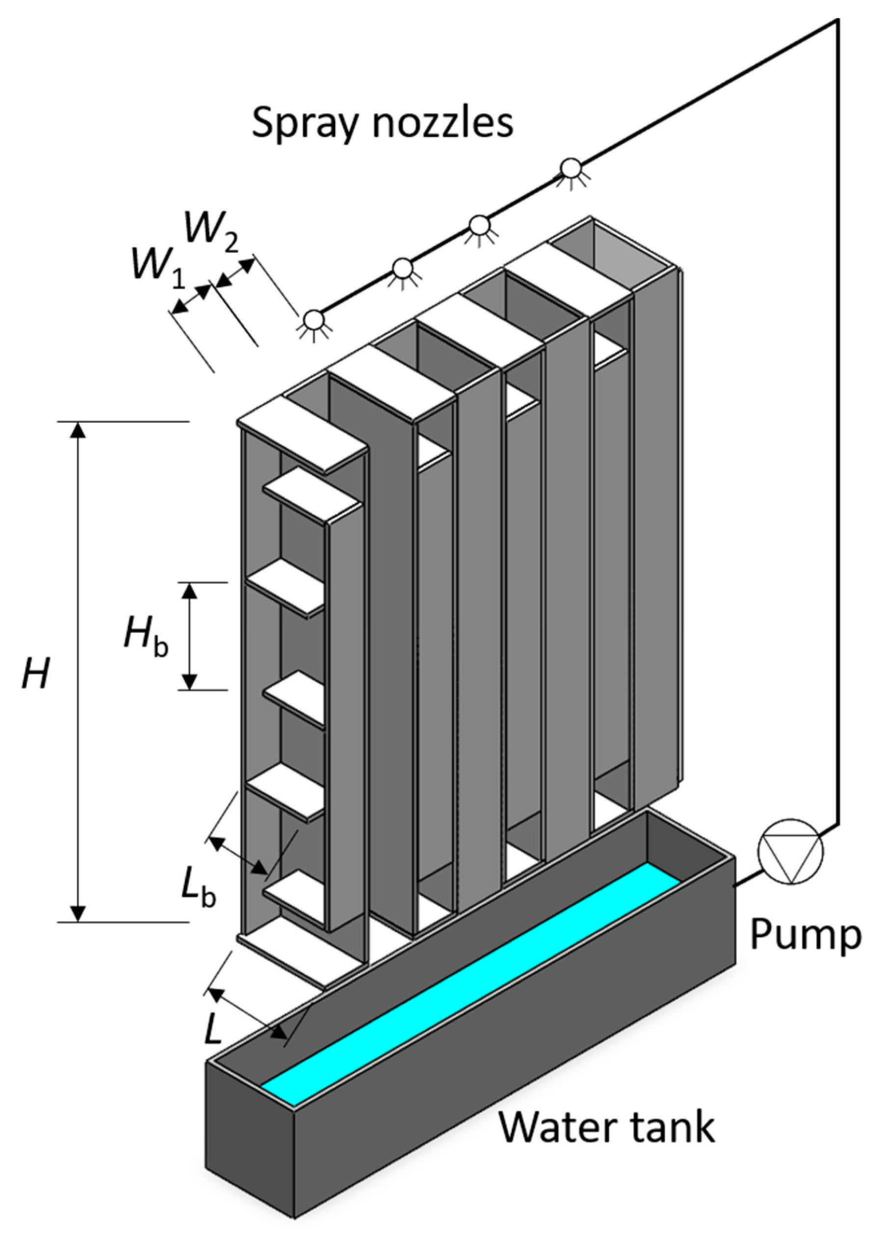
3.1. Physical Model

As the vertical PIEC shown as Figure 1 can be considered a composite of multiple units with identical functions, one unit shown in Figure 2 is selected as the physical model in this paper, which primarily consists of half dry channel with half width (W1/2), half wet channel with half width (W2/2), and a heat exchange plate between two channels.

3.2. Numerical Model and Method

3.2.1. Prerequisite Assumptions

The idealizations of a small number of interference factors in advance to obtain a valid numerical model is needed to directly pursue the research purpose with fewer interruptions and to reduce computing resource consumption. The following assumptions have been made while ensuring the accuracy of the simulation.
(1)
The heat and mass transfer process are stable.
(2)
In channels, the properties of water film and air are considered to be stable, uniform, and incompressible, and the mixture of air and water vapor is considered to be an ideal gas.
(3)
The PIEC does not exchange heat and mass with the surroundings.
(4)
The effects of droplet splash, separation, collection, breakup, contact angle, and sharp angles of water film are neglected.
(5)
The circulating water forms a stable and uniform water film on the inner surface of the wet channel, and the maximum water film thickness is 5 mm.
(6)
This numerical model is only used for the PIEC in dry areas, regardless of condensation.

3.2.2. Numerical Method and Boundaries

In this study, based on the FVM (Finite Volume Method), the Euler wall film model and the phase change model are used for the water film and phase change, respectively. As the k-ε realizable model is able to simulate the mixed flow composited of the high Reynold number fluid and the low one more accurately, the k-ε realizable model is selected for the air flow in the computing domain.
The primary air inlet and the secondary air inlet are all specified as the velocity inlet boundary, their outlets are all defined as the pressure outlet boundary, the left and right sides of the unit are the symmetric boundary, and other boundaries are designated as the wall boundary. Additionally, the inner surface of the wet channel is designated as a Euler wall film boundary.
Because PIEC can be more effective in the dry areas, the city of Lanzhou located in Northwest China is selected as the user in this paper. Table 2 gives the operation parameters of the PIEC based on the meteorological parameters of Lanzhou city and references [14,36].

3.2.3. Numerical Model Equations

With the help of Fluent software, which is a part of ANSYS 2022 R1, air temperature, velocity, and pressure in the calculation field are solved by coupling the continuity equation, energy conservation equation, and momentum conservation equation. The governing equations used in this research are as follows.
For the air in the dry channel and the wet channel, the continuity equation, the momentum conservation equation, and the energy conservation equation are given in Equations (1), (2) and (3), respectively [38].
ρ v = S e
ρ v v = P + ρ f
ρ v E = ρ f v + P v + k Δ T + S e
Here, S e is the source item produced by evaporation, f is body force, and P is surface force item.
For the water film in the wet channel, the continuity equation, momentum conservation equation, and the energy conservation equation are defined as Equations (4)–(6) [38].
f ρ f δ f V f = S e
f ρ f δ f V f V f + A v = h f p F + ρ f δ f g f + 3 2 τ w , f 3 μ f δ f V f
f ρ f δ f T f + A T = 1 C P 2 k f h T fs + T fw 2 T fh + m ˙ e q m
Here, the subscript fs denotes the interfacial region between the water film and secondary air, fw refers the boundary between the water film and heat exchange wall, and fh refers the central plane of the water film. A v and A T denote the differential advection term computed on the basis of the quadratic film velocity profile representation. pF includes the effects of gas-flow pressure, the gravity component normal to the wall surface, and surface tension. The second term on the right of Equation (5) represents the effect of gravity in the direction parallel to the film; the third and fourth terms on the right of Equation (5) represent the net viscous shear force on the gas–film and film–wall interfaces, based on the quadratic film velocity profile representation [38]. e is the water-evaporation mass flow rate. qm is the latent heat of water evaporation.
For the water film in the wet channel, evaporation can be calculated according to Equation (7).
m ˙ e = ρ 2 D v / δ f ρ 2 D v δ f + C e C e c s c 2
Here, Dv is the mass diffusivity of the vapor species. cs is the air mass fraction at the saturation defined in Equation (8). The saturated vapor pressure Ps and the mass fraction c of water vapor at the gas–liquid interface can be calculated according to Equations (9) and (10). The absolute humidity d and the relative humidity φ are defined as Equation (11) and Equation (12), respectively. δf is the water film thickness [38].
c s = P s M v P 2 M 2
lg P s = 2.1794 + 0.02953 T 9.1837 × 10 5 T 2 + 1.4454 × 10 7 T 3
c = d d + 1000 = 0.622 P s 0.622 P s + 1000 B P s
d = 0.622 φ P s B φ P s
φ = P v P s
For the heat exchange plate between the dry channel and the wet channel, the heat exchange energy conservation equation is defined as Equation (13).
k w grad T = k f T z
k is the thermal conductivity. The subscript w and f are the heat exchange wall and the water film, respectively.

3.2.4. Evaluation Index

The wet bulb efficiency (ηwb) and the dew-point efficiency (ηdp) are used to indicate the outlet temperature of the primary air close to the wet bulb temperature and the dew-point temperature of the inlet primary air, respectively.
η wb = T 1 T 1 T 1 T 1 , wb × 100 %
η dp = T 1 T 1 T 1 T 1 , dp × 100 %
The superscript ′ and ″ are the inlet and outlet of air, respectively.
The local heat transfer coefficient (hi) and the average heat transfer coefficient (h) are used to indicate the heat exchange intensity per unit area of the dry channel wall.
h i = N u k D
h = 1 A h i d A
Nu is the Nusselt number. D is the hydraulic diameter. A is the heat exchange area.
The cooling capacity per-unit area (q) is an evaluation index used in this paper.
q = Q c A w + A b
Here, Qc is the cooling capacity of primary air. The subscript b is the baffle.
The flow resistance will also increase when the heat transfer is enhanced by adding baffles in the dry channel. In this study, the comprehensive performance evaluation index i [39] is used to indicate its worth. The resistance coefficient f shown in Equation (19) is used to evaluate the negative effects of baffles on PIEC resistance. When i is greater than 1, the total effect of adding baffles on the performance of PIEC is beneficial.
f = 2 Δ P ρ v 2 D L
i = N u i N u o ( f o f i ) 1 3
Here, ΔP is a pressure drop. The subscript i and o are PIECs with and without baffles, respectively.

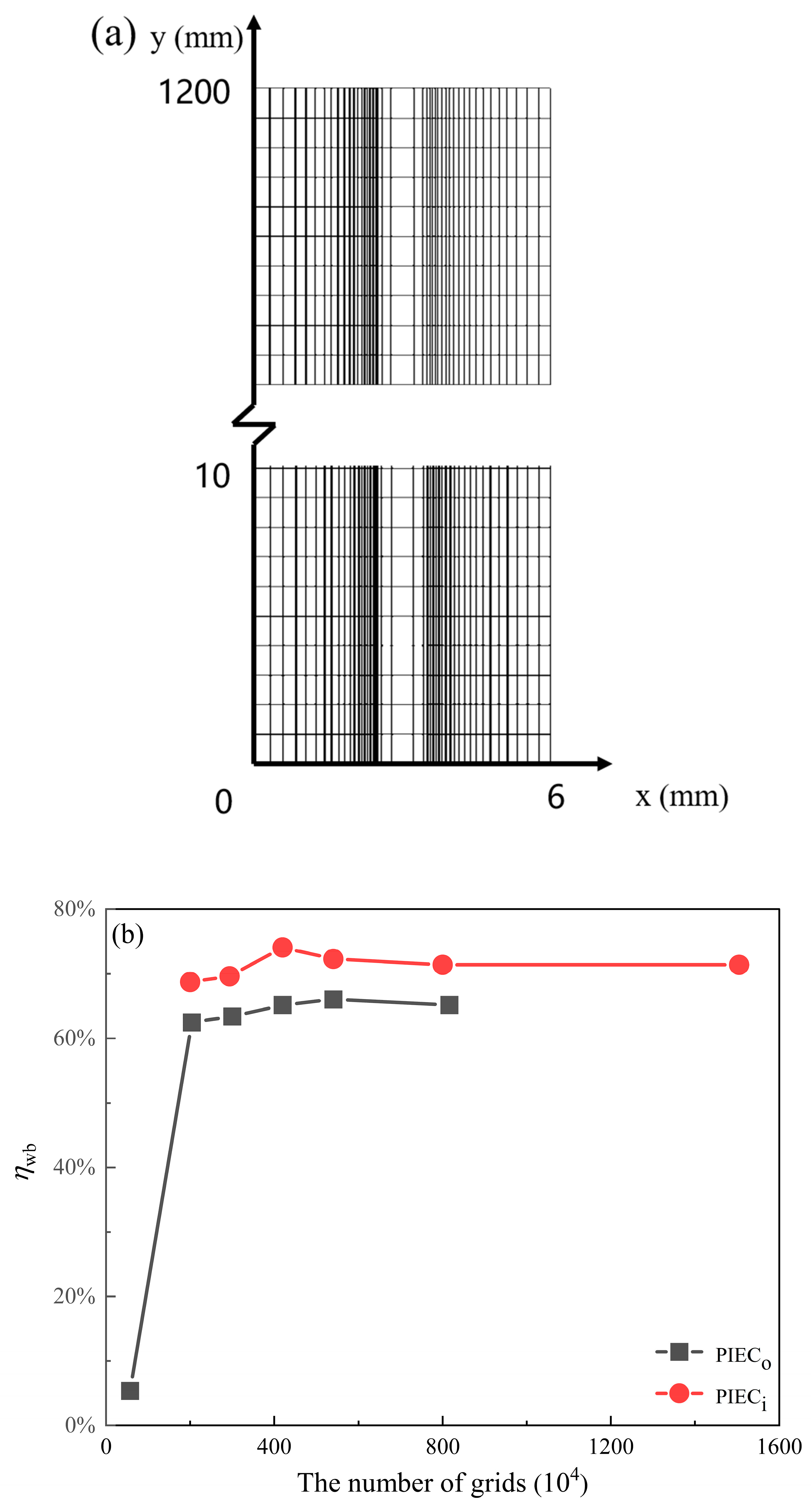
3.3. Mesh Generation and Independence Assessment

The 3-D physical model depicted in Figure 2 is discretized with the structured hexahedral mesh. In the regions of the heat exchange plate and the water film, the mesh was locally refined, as shown in Figure 3a. To obtain the independent mesh from the calculation result, six sets of meshes are used to calculate the dew-point efficiencies of the PIECs without baffles, whose cell numbers are from 0.57 × 10⁶ to 8.16 × 10⁶, and the same method is used for the PIECs with baffles, whose cell numbers are from 2 × 10⁶ to 15.05 × 10⁶. Based on the calculation results shown in Figure 3b, the mesh with 4.2 × 10⁶ cells for the PIECs without baffles and the mesh with 5.4 × 10⁶ cells for the PIECs with baffles are selected for the next numerical calculation, which has a cell volume from 3.13 × 10⁻¹¹ m3 to 4.9 × 10⁻¹⁰ m3.

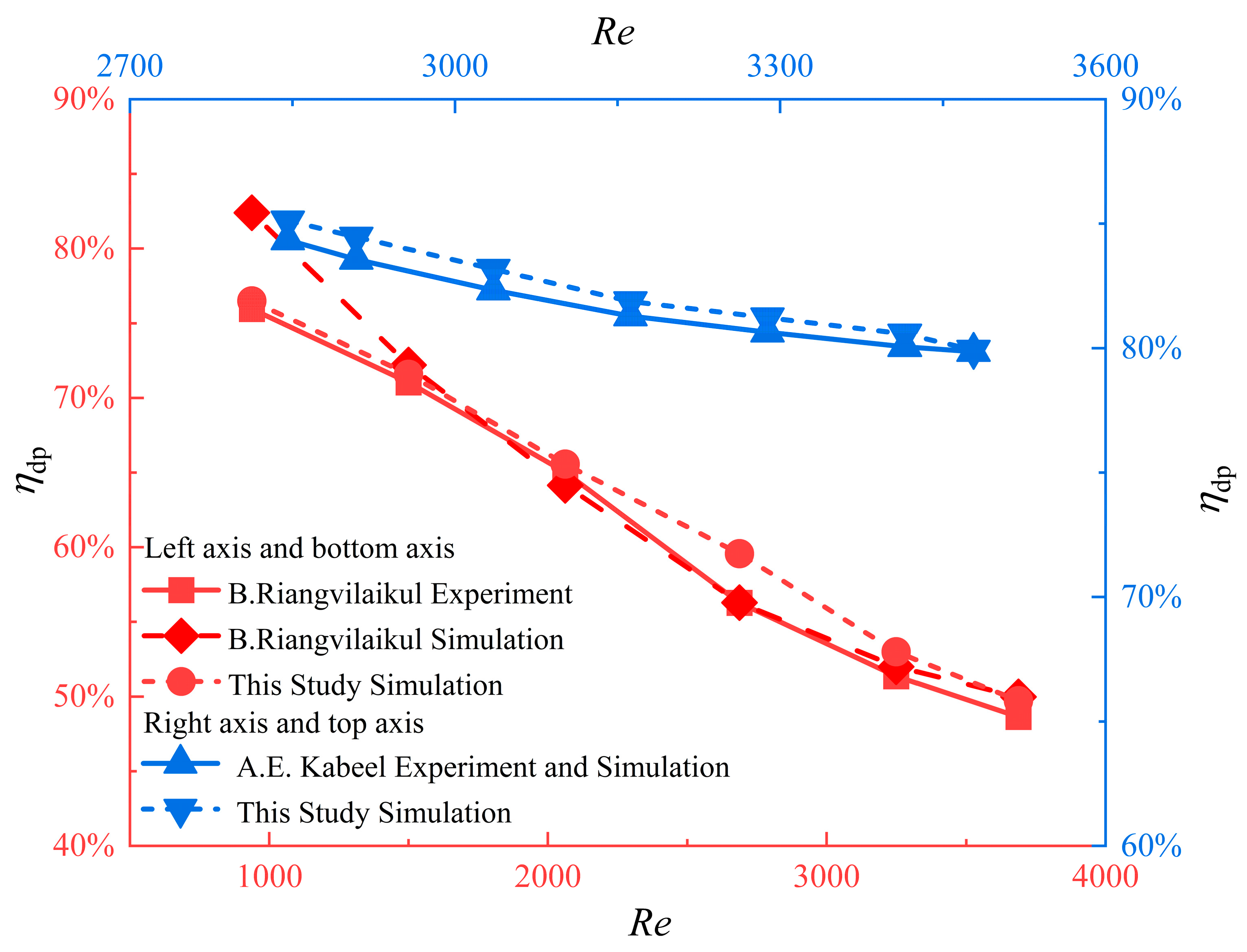
3.4. Validation of Numerical Model and Method

Figure 4 shows the dew-point efficiency (ηdp) of PIECs without baffles tested by B. Riangvilaikui [40] under conditions with an Re range of 937–3687, a dry bulb temperature of 34 °C, and a wet bulb temperature of 21.6 °C at the dry channel inlet on the left Y-axis and the bottom X-axis, and that of PIECs with baffles tested by A. E. Kabeel [25] under conditions with an Re range of 2846–3478, a dry bulb temperature of 35 °C, and a wet bulb temperature of 24 °C at the dry channel inlet on the right Y-axis and the top X-axis. The increase in Re induced by the primary air velocity leads to an increase in flow and a decrease in heat transfer time of the primary air, which raises the outlet temperature of the primary air and lowers the dew-point efficiency of PIEC.
As the Lewis number is dependent on the environment [36], based on a substantial amount of tests, B. Riangvilaikul [41] obtained a reasonable Lewis number corresponding to the test conditions and by which, carried out the numerical calculation for PIECs in the same condition as the experiment [40]. The simulation result shown in Figure 4 exhibits a maximum deviation of 8.5% and an average deviation of 2.6%.
In order to verify the numerical model and method provided by this study, the same physical models as references [25,40] are built and calculated under the same conditions, respectively. The results are also given in Figure 4. Furthermore, as uneven water distribution and uneven water film could exist in the experiment, the test results are poorer than that of the numerical simulation, but the maximum deviation is less than 10% between the results based on the numerical method provided in this paper and the experimental results provided by references [25,40]. Compared to the numerical method provided by B. Riangvilaikui [40], the numerical method provided in this paper is also effective, but it is independent of the accuracy of the Lewis number, and so, it is simpler and has a wider adaptability.

4. Results and Discussion

Based on the conditions shown in Table 1 and Table 2, and the numerical model and method provided in this paper, the impact of baffle length on the vertical PIEC performance is firstly indicated.

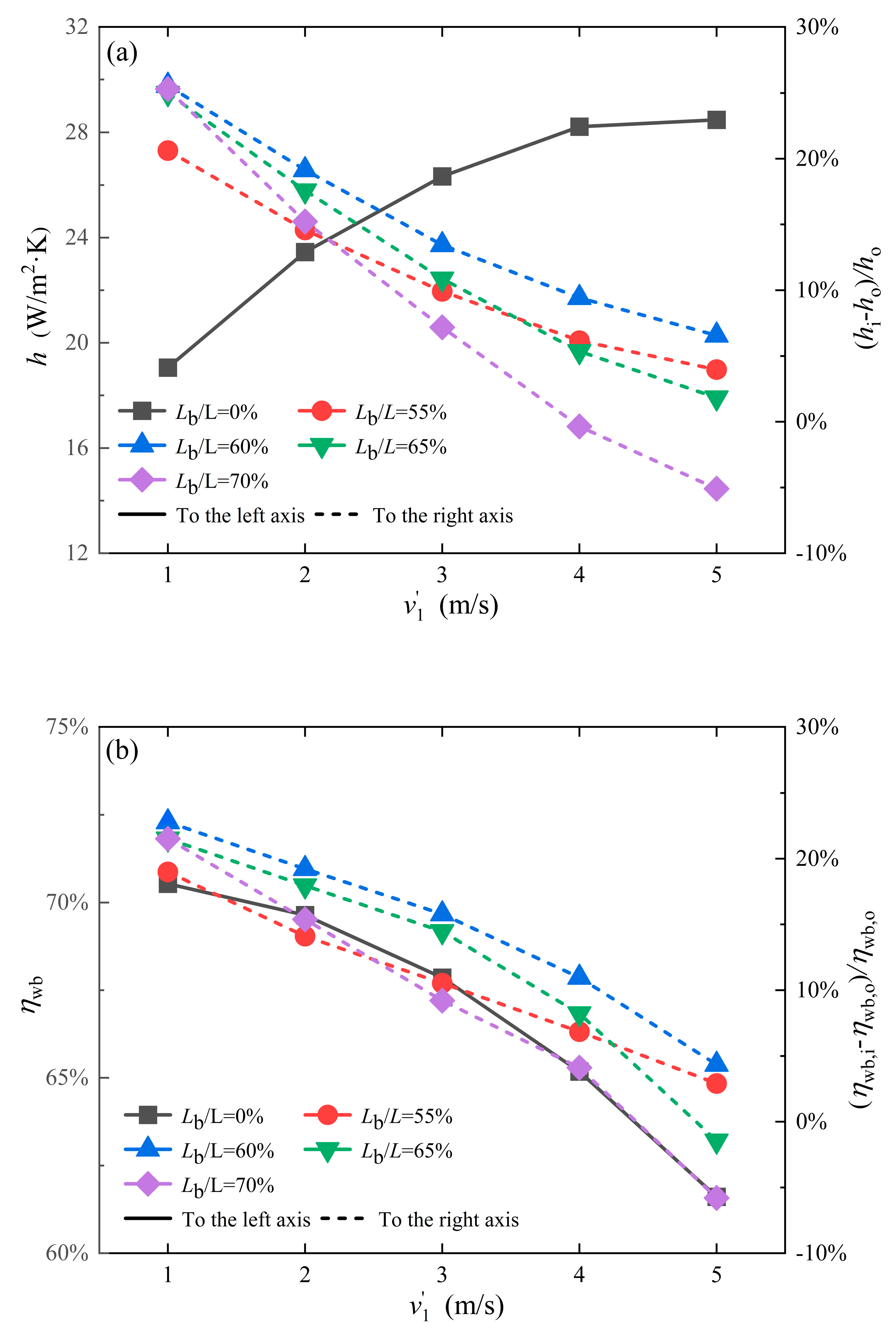
4.1. Baffle Length Influence

In this section, the impact of baffle structure size on the performance of IEC, which has not been addressed in previous studies, was investigated. Four dimensionless baffle lengths (Lb/L) of 55%, 60%, 65%, and 70% are selected. The conditions are the same as those mentioned above, except for the primary air inlet velocities. The results are shown in Figure 5.
Figure 5a shows the average surface heat transfer coefficient in the dry channel of PIECs without baffles on the left Y-axis and its improvement ratios coming from baffles with four lengths on the right Y-axis, respectively, to the inlet velocity of the primary air. When the inlet velocity of the primary air in PIECs without baffles increases, the average heat transfer coefficient significantly increases until 3 m/s, and when the inlet velocity is greater than 4 m/s, the velocity effect is no longer remarkable. Since larger local velocities and more vortexes are induced by the baffles, the baffles effect on improving the total heat transfer coefficient in the dry channel is also significant, especially that of the baffles of 60% relative length, whose improvement ratio is more than 25% at the inlet velocity 1 m/s. Furthermore, because the area share occupied by the flow at a lower local velocity is dominant when the relative length of the baffle biases from 60%, the baffle effect on the heat transfer coefficient is weakened, especially for PIECs at the higher inlet velocity. The heat transfer coefficient is adversely affected when the relative length of the baffle exceeds 70% and the primary air inlet velocity surpasses 4m/s. When the inlet velocity of the primary air is 4 m/s, the average surface heat transfer coefficients in the dry channel of PIECs with baffles in the relative lengths of 55%, 60%, 65%, and 70% are 29.96, 30.88, 29.73, and 28.12 W/m2∙K, respectively.
Figure 5b shows the wet bulb efficiency of PIECs without baffles on the left Y-axis and its improvements coming from baffles with four lengths on the right Y-axis, respectively. The wet bulb efficiency of PIECs without baffles is more than 70% when the primary air inlet velocity is 1 m/s, but it sharply decreases with the inlet velocity increasing. Increasing primary air flow and shortening heat transfer time results in the primary air outlet temperature rising. Compared to PIEC without baffle, the primary air in PIECs with baffles will have a longer distance and more time in heat transfer with the wall, which results in the baffle’s remarkable effect on the wet bulb efficiency, especially for PIECs with baffles of 60% relative length. For the same reason as in Figure 5a, when the inlet velocity increases or the relative length of the baffle biases from 60%, the baffle advantage will be weakened significantly. When the inlet velocity of the primary air is 4 m/s, the wet bulb efficiencies of PIECs with baffles with relative lengths of 55%, 60%, 65%, and 70% are 69.64%, 72.32%, 70.54%, and 67.86%, respectively. The improved ratios on the wet bulb efficiency of PIECs with baffles of 60% relative length is more than 20%.
Figure 5c shows the cooling capacity per-unit area of PIEC on the left axis to the inlet velocity of the primary air. Since the average heat transfer coefficient and the corresponding temperature difference between the dry channel and the wet channel all increase with the inlet velocity increasing, the cooling capacity is significantly improved. The velocity effect on the cooling capacity begins to weaken until 4 m/s. For the same reason as the velocity effect, compared to PIECs without baffles, the cooling capacities of PIECs with baffles are all improved as the velocity increases, notably in PIECs with baffles of 60% relative length, which is 85.17 W/m2 at 4 m/s. The effect of baffles on the cooling capacity is weakened when the inlet velocity is greater than 4 m/s.
Although adding baffles and increasing velocity can effectively improve heat transfer of PIECs, more flow resistance of the primary air is also induced. When i is more than 1, the effect is that measures are improved. The comprehensive performance evaluation index i (shown in Figure 5c on the right axis) can indicate the balance point between the heat transfer and the flow resistance induced by the baffles and the inlet velocity. When the inlet velocity is at a low level, the i value of the PIECs are all favorable. PIECs with baffles of 60% relative length are still the most favorable, notably when i is greater than 1.2 at an inlet velocity of 2 m/s. The pressure loss gradually increases with the increase of primary air inlet velocity and length of the baffle. When the relative length biases from 60% or the inlet velocity increases, i rapidly deteriorates.

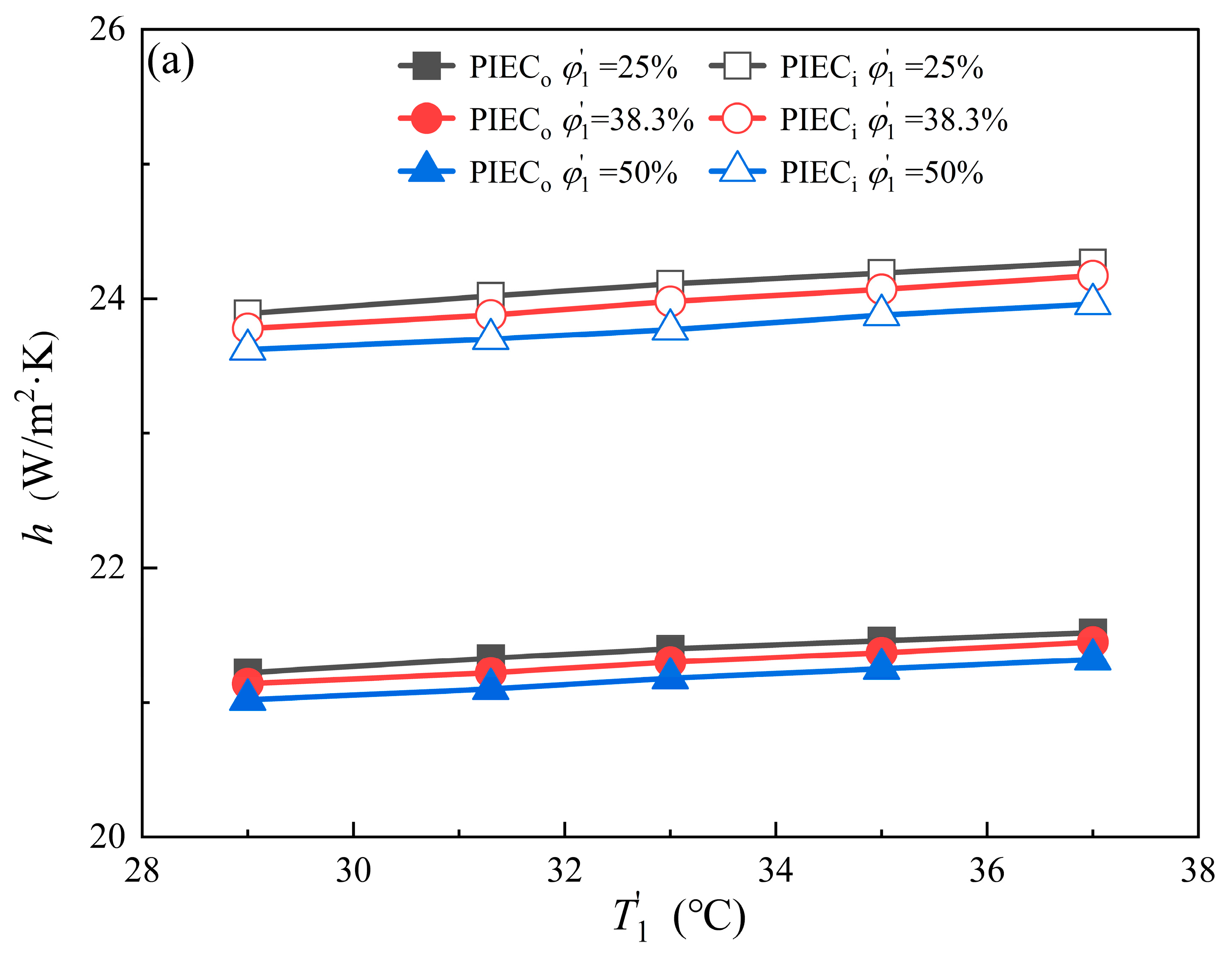
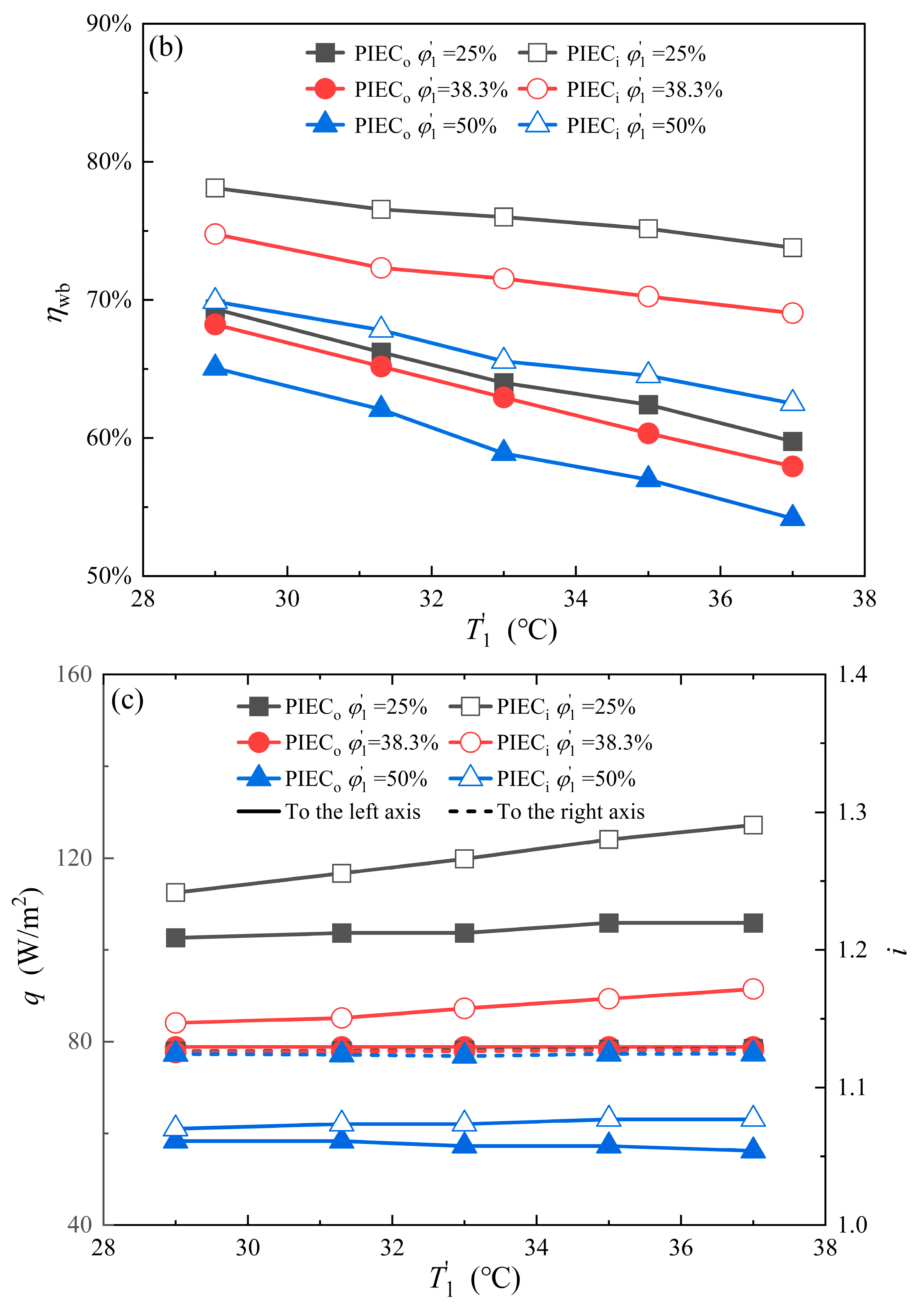
4.2. Parameter Influence of Inlet Air

To indicate baffle impact on PIEC performance depending on the inlet air parameter, this section selects 15 kinds of inlet airs based on five temperatures and three humidities. The objective of this section is to investigate the applicability of the PIEC with the baffle in diverse climatic conditions. The inlet parameter of the primary air is the same as that of the secondary air, the relative length of the baffle is 60%, and the other conditions are the same as those mentioned above. The results are illustrated in Figure 6.
Figure 6a shows the dependence of the average heat transfer coefficient of the PIEC dry channel on the inlet temperature and humidity of the primary air. When the inlet air temperature increases, its molecular kinetic energy also enhances, and when the inlet air humidity decreases, the cooling capacity per-unit area of the PIEC also increases, which all help to improve the average heat transfer coefficient, but this improvement effect is very small. Compared to PIECs without baffles, the inlet air temperature and humidity influence on the average heat transfer coefficient of PIECs with baffles is more significant due to the faster flow rate and the greater number of vortices as a result of the baffles. In conclusion, the impact of inlet air temperature and humidity on the heat transfer coefficient is inapparent.
Figure 6b shows the dependence of the wet bulb efficiency of PIECs on the inlet air temperature and humidity of the primary air. When the inlet air temperature increases, the outlet air temperature has a corresponding increase, but the change of the corresponding wet bulb temperature and the cooling capacity of PIECs are not significant, which results in the wet bulb efficiency decrease. In addition, because the baffle effect on the heat transfer is positive, the cooling capacity and the wet bulb efficiency of PIECs with baffles are better than that of PIECs without baffles. The baffle can significantly enhance the wet bulb efficiency of PIECs under conditions characterized by high temperature and low relative humidity of inlet air. Under conditions with an inlet air temperature of 37 °C and a relative humidity of 25%, the wet bulb efficiency of PIECs has an increased ratio of 23.5% induced by baffles.
Figure 6c illustrates the impact of the inlet temperature and humidity of the primary air on the cooling capacity per-unit area of PIEC. The effect of the inlet air humidity and the baffles on the cooling capacity is positive and significant. When the inlet air temperature increases, the cooling capacity per-unit area of PIEC with baffles has an increase of 1.84 W/m2, which is caused by the increase of the heat transfer coefficient and the temperature difference between the primary air and the wall. In conditions with an inlet air temperature of 37 °C and a relative humidity of 25%, the cooling capacity per-unit area of PIECs with baffles reaches 127 W/m2. The humidity effect on the cooling capacity of PIECs without baffles is very small.
Because the heat transfer coefficient and the pressure loss caused by baffles in the dry channel are all insensitive to the inlet air temperature and humidity, the comprehensive performance evaluation index (shown as Figure 6c) also exhibits independence from the inlet air temperature and humidity.

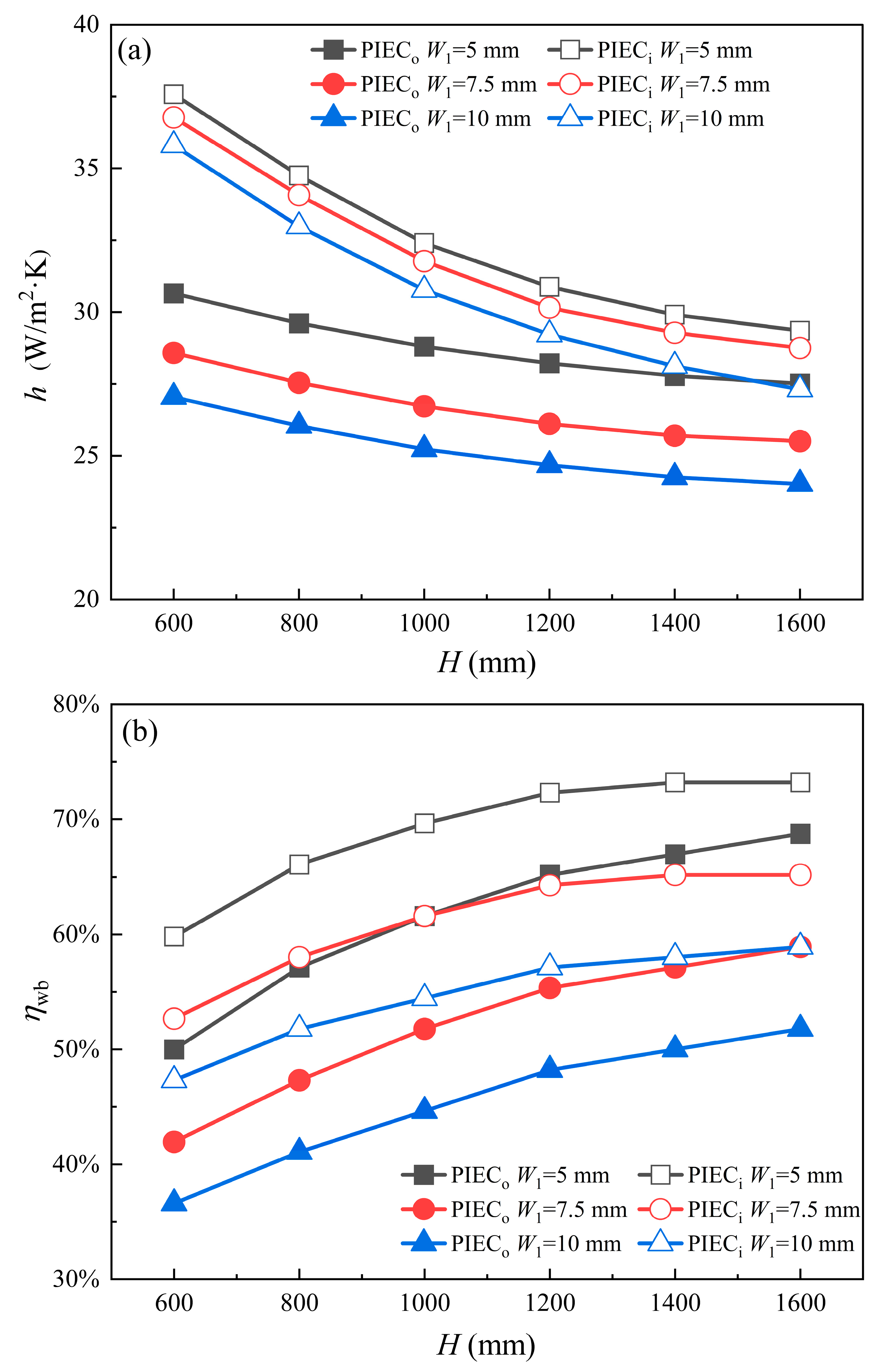
4.3. Channel Size Influence

In this section, the dependence of the baffle effect on PIEC performance to the channel structure is analyzed based on 18 kinds of channels. The impact of channel structure size on the performance of the baffle in terms of IEC, which was not addressed in the previous study, was investigated. Except for the channel height and width, the other conditions are the same as those mentioned above. The results are shown in Figure 7.
Figure 7a shows the structure influence of PIEC channels on the average heat transfer coefficient in the dry channel. When the channel height increases, the local heat transfer coefficient and the temperature difference between the primary air and the wall are all decreased down the channel, which results in a decrease in the average heat transfer coefficient, especially in PIECs with baffles. In the same inlet velocity conditions, the dry channel structural dimension variation results in a decrease in the heat transfer coefficient. When the dry channel has a low height and a large width, the inclusion of baffles can significantly enhance heat transfer. In conditions with a 600 mm channel height and 5 mm, 7.5 mm, and 10 mm dry channel widths, the increased ratios of the heat transfer coefficient of PIECs with baffles are 22.6%, 28.7%, and 32.4%, respectively.
The channel structure influence on the wet bulb efficiency of PIECs is illustrated in Figure 7b. As the channel height increases, the wet bulb efficiency gradually improves because the heat transfer time and the distance of the primary air increases and the outlet air temperature decreases. However, the improvement effect becomes more and more insignificant because the temperature difference between the primary air and the wall gradually decreases. An increase in dry channel width leads to a gradual decrease in the wet bulb efficiency due to the decrease in the heat transfer coefficient and an increase in primary air flow. The incorporation of baffles in PIECs leads to a significant enhancement in wet bulb efficiency due to its improvement in heat transfer, especially when the dry channel height is low and the width is large. In conditions with a channel height of 600 mm and dry channel widths of 5 mm, 7.5 mm, and 10 mm, the increased ratios in wet bulb efficiency are 19.6%, 25.5%, and 29.3%, respectively.
Figure 7c illustrates the relationship between the cooling capacity per-unit area of PIEC and the channel structure. As the channel height increases, the heat transfer area increases, and although the total cooling capacity gradually increases, the cooling capacity per unit area decreases because the heat transfer coefficient and the temperature difference between the dry channel and the wet channel decrease. Under the the same conditions of inlet air velocity, as the width of the dry channel increases, the temperature difference between dry and wet channels and primary air flow increases, which results in an increase in cooling capacity. Due to the same reasons mentioned above, the baffle has a positive and remarkable effect on the cooling capacity under the same structure conditions. In conditions with a dry channel height of 600 mm and widths of 5 mm, 7.5 mm, and 10 mm, the cooling capacity per-unit area of PIEC with baffles is 141.2 W/m2, 186.6 W/m2, and 223.5 W/m2, respectively.
Figure 7c indicates the relationship between the baffle effect on PIEC performance compared to PIECs without baffles and the dry channel structure. As the height of the channel increases, the comprehensive performance evaluation index i rapidly decreases due to a reduction in the heat transfer coefficient and an increase in pressure loss. Moreover, because the pressure loss of the primary air rapidly decreases when the dry channel widens, i is improved. The baffle added in the dry channel is worth doing, especially with the low channel height and large channel width mentioned in this paper.

5. Conclusions

To fill in the research gap relating to the influence baffle length has on PIEC performance and to indicate the significance of the baffle effect, this paper provides and verifies a simpler numerical method based on the Euler wall film model and the species transport model, and numerically analyzes the baffle effect on wet bulb efficiency, the average heat transfer coefficient, and the comprehensive performance evaluation index of PIECs. The conclusions are as follows.
(1)
The numerical model and method proposed in this study is simpler and effective. The method obviates the need for an empirical estimation of Lewis number in simulations, and only necessitates a high-quality mesh in the water film region. The maximum deviation between the simulation results obtained using the numerical simulation method proposed in this study and the experimental and simulation results reported in the references is below 10%.
(2)
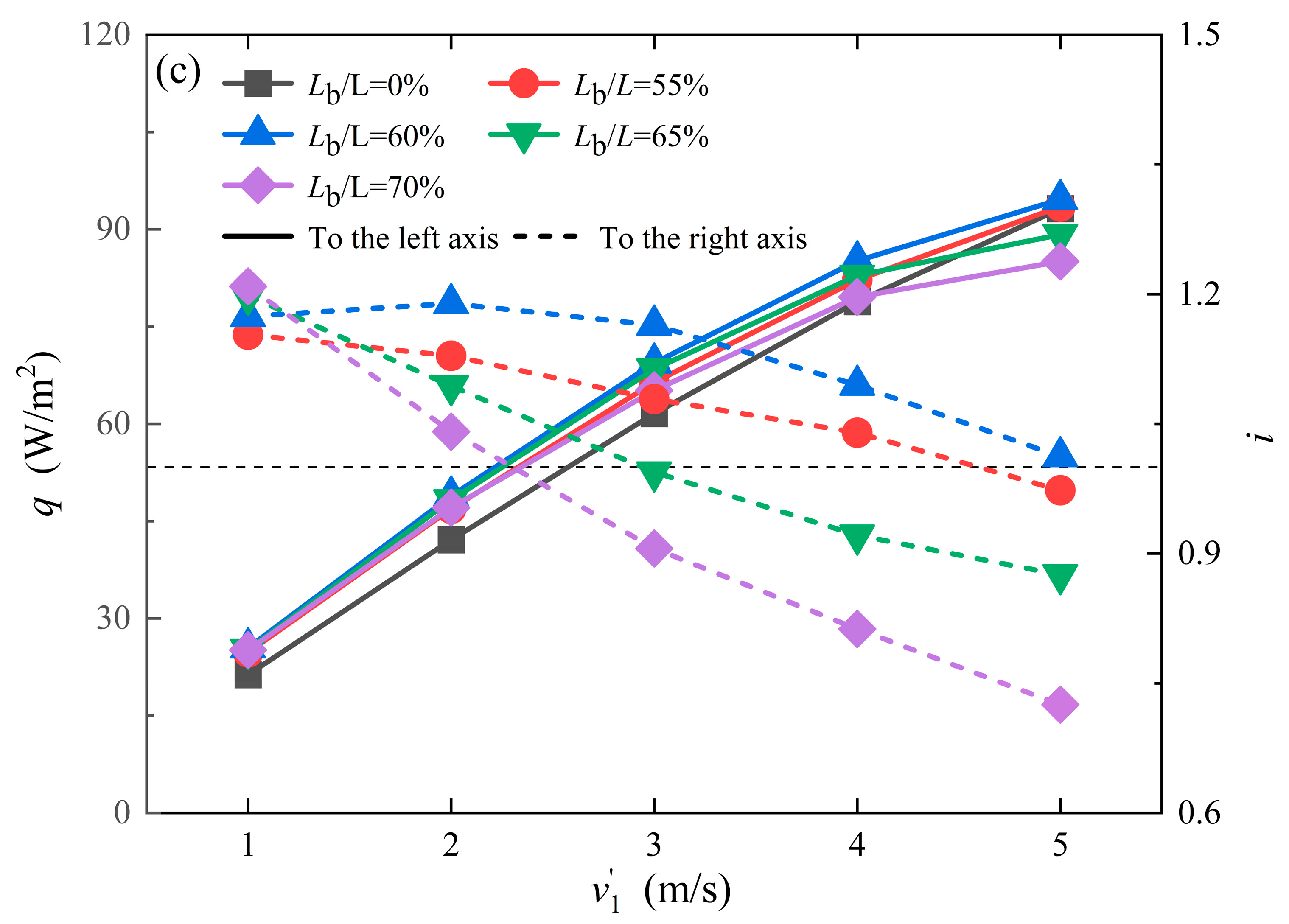
The baffle effect on PIEC performance is dependent on the baffle length, the channel size, and the inlet air parameters. A relative length of 60% is recommended in this research. The baffle can significantly enhance the wet bulb efficiency of PIECs by up to 22.8–29.3%.
(3)
Although the baffle effect on PIEC performance is positive, the additional resistance induced by the baffle is not neglected, and so, the comprehensive performance evaluation index is needed. When the channel length is shorter and the width is wider, the comprehensive evaluation coefficient can significantly increase up to 1.88. When the Lb/L exceeds 60% and the primary air velocity exceeds 4 m/s, the comprehensive performance evaluation index will be less than 1 due to the excessive pressure loss, which is detrimental to PIEC performance.
The follow-up work will be focused on the performance improvement of PIECs with M-cycle and baffles by using the numerical model and method proposed in this study.

Author Contributions

Conceptualization, W.Z.; methodology, S.C.; software, S.C.; validation, S.C.; formal analysis, J.W.; investigation, Y.L.; resources, W.Z.; data curation, J.W.; writing—original draft preparation, S.C.; writing—review and editing, W.Z.; visualization, S.C.; supervision, W.Z.; project administration, W.Z.; funding acquisition, W.Z. All authors have read and agreed to the published version of the manuscript.

Funding

This research received no external funding.

Data Availability Statement

Data are contained within the article.

Conflicts of Interest

Authors Jia Wang and Yong Liu were employed by the company Central & Southern China Municipal Engineering Design and Research Institute Co., Ltd. The remaining authors declare that the research was conducted in the absence of any commercial or financial relationships that could be construed as a potential conflict of interest.

References

  1. Jing, Y.; Xie, X.; Jiang, Y. Performance comparison and suitable climatic zones of three water-mediated evaporative cooling technologies. Energy Convers. Manag. 2023, 277, 116637. [Google Scholar] [CrossRef]
  2. Jamil, M.A.; Imtiaz, N.; Ng, K.C.; Xu, B.B.; Yaqoob, H.; Sultan, M.; Shahzad, M.W. Experimental and parametric sensitivity analysis of a novel indirect evaporative cooler for greener cooling. Therm. Sci. Eng. Prog. 2023, 42, 101887. [Google Scholar] [CrossRef]
  3. Pacak, A.; Worek, W. Review of Dew Point Evaporative Cooling Technology for Air Conditioning Applications. Appl. Sci. 2021, 11, 934. [Google Scholar] [CrossRef]
  4. Shukla, D.L.; Modi, K.V. Influence of distinct input parameters on performance indices of dehumidifier, regenerator and on liquid desiccant-operated evaporative cooling system—A critical review. Renew. Sustain. Energy Rev. 2022, 168, 112834. [Google Scholar] [CrossRef]
  5. Mohammed, R.H.; El-Morsi, M.; Abdelaziz, O. Indirect evaporative cooling for buildings: A comprehensive patents review. J. Build. Eng. 2022, 50, 104158. [Google Scholar] [CrossRef]
  6. Zhao, C.-Y.; Liang, L.-W.; Qi, D.; Ji, W.-T.; Tao, W.-Q. The effect of gas streams on the hydrodynamics, heat and mass transfer in falling film evaporation, absorption, cooling and dehumidification: A comprehensive review. Build. Environ. 2022, 219, 109183. [Google Scholar] [CrossRef]
  7. Chen, Y.; Yan, H.; Min, Y. Visualized study of wetting enhancement and thermal performance of fiber-coated indirect evaporative cooler. Appl. Therm. Eng. 2023, 221, 119904. [Google Scholar] [CrossRef]
  8. Zhu, G.; Chen, W.; Zhang, D.; Wen, T. Performance evaluation of counter flow dew-point evaporative cooler with a three-dimensional numerical model. Appl. Therm. Eng. 2023, 219, 119483. [Google Scholar] [CrossRef]
  9. Zhu, G.; Wen, T.; Wang, Q.; Xu, X. A review of dew-point evaporative cooling: Recent advances and future development. Appl. Energy 2022, 312, 118785. [Google Scholar] [CrossRef]
  10. Pacak, A.; Jurga, A.; Kaźmierczak, B.; Pandelidis, D. Experimental verification of the effect of air pre-cooling in dew point evaporative cooler on the performance of a solid desiccant dehumidifier. Int. Commun. Heat Mass Transf. 2023, 142, 106651. [Google Scholar] [CrossRef]
  11. Cui, X.; Chua, K.J.; Islam, M.R.; Ng, K.C. Performance evaluation of an indirect pre-cooling evaporative heat exchanger operating in hot and humid climate. Energy Convers. Manag. 2015, 102, 140–150. [Google Scholar] [CrossRef]
  12. Wan, Y.; Huang, Z.; Soh, A.; Jon Chua, K. On the performance study of a hybrid indirect evaporative cooling and latent-heat thermal energy storage system under commercial operating conditions. Appl. Therm. Eng. 2023, 221, 119902. [Google Scholar] [CrossRef]
  13. Chakraborty, S.; Vernon, D.; Jha, A.; Narayanan, V. Performance characterization of M-cycle indirect evaporative cooler and heat recovery ventilator for commercial buildings—Experiments and model. Energy Build. 2023, 281, 112762. [Google Scholar] [CrossRef]
  14. Kabeel, A.E.; Bassuoni, M.M.; Abdelgaied, M. Experimental study of a novel integrated system of indirect evaporative cooler with internal baffles and evaporative condenser. Energy Convers. Manag. 2017, 138, 518–525. [Google Scholar] [CrossRef]
  15. Moshari, S.; Heidarinejad, G.; Fathipour, A. Numerical investigation of wet-bulb effectiveness and water consumption in one-and two-stage indirect evaporative coolers. Energy Convers. Manag. 2016, 108, 309–321. [Google Scholar] [CrossRef]
  16. Yang, H.; Shi, W.; Chen, Y.; Min, Y. Research development of indirect evaporative cooling technology: An updated review. Renew. Sustain. Energy Rev. 2021, 145, 111082. [Google Scholar] [CrossRef]
  17. Abdullah, S.; Zubir, M.N.B.M.; Muhamad, M.R.B.; Newaz, K.M.S.; Öztop, H.F.; Alam, M.S.; Shaikh, K. Technological development of evaporative cooling systems and its integration with air dehumidification processes: A review. Energy Build. 2023, 283, 112805. [Google Scholar] [CrossRef]
  18. Min, Y.; Chen, Y.; Yang, H. Investigation on dynamic behaviour of condensation heat transfer in indirective evaporative cooler. Indoor Built Environ. 2020, 31, 2024–2035. [Google Scholar] [CrossRef]
  19. Yang, Y.; Cui, G.; Lan, C.Q. Developments in evaporative cooling and enhanced evaporative cooling—A review. Renew. Sustain. Energy Rev. 2019, 113, 109230. [Google Scholar] [CrossRef]
  20. Lee, J.; Choi, B.; Lee, D.-Y. Comparison of configurations for a compact regenerative evaporative cooler. Int. J. Heat Mass Transf. 2013, 65, 192–198. [Google Scholar] [CrossRef]
  21. Lee, J.; Lee, D.-Y. Experimental study of a counter flow regenerative evaporative cooler with finned channels. Int. J. Heat Mass Transf. 2013, 65, 173–179. [Google Scholar] [CrossRef]
  22. Duan, Z.; Zhan, C.; Zhao, X.; Dong, X. Experimental study of a counter-flow regenerative evaporative cooler. Build. Environ. 2016, 104, 47–58. [Google Scholar] [CrossRef]
  23. Liu, Y.; Akhlaghi, Y.G.; Zhao, X.; Li, J. Experimental and numerical investigation of a high-efficiency dew-point evaporative cooler. Energy Build. 2019, 197, 120–130. [Google Scholar] [CrossRef]
  24. Ali, M.; Ahmad, W.; Sheikh, N.A.; Ali, H.; Kousar, R.; ur Rashid, T. Performance enhancement of a cross flow dew point indirect evaporative cooler with circular finned channel geometry. J. Build. Eng. 2021, 35, 101980. [Google Scholar] [CrossRef]
  25. Kabeel, A.E.; Abdelgaied, M. Numerical and experimental investigation of a novel configuration of indirect evaporative cooler with internal baffles. Energy Convers. Manag. 2016, 126, 526–536. [Google Scholar] [CrossRef]
  26. Moshari, S.; Heidarinejad, G. Analytical estimation of pressure drop in indirect evaporative coolers for power reduction. Energy Build. 2017, 150, 149–162. [Google Scholar] [CrossRef]
  27. Cui, X.; Chua, K.J.; Islam, M.R.; Yang, W.M. Fundamental formulation of a modified LMTD method to study indirect evaporative heat exchangers. Energy Convers. Manag. 2014, 88, 372–381. [Google Scholar] [CrossRef]
  28. Anisimov, S.; Pandelidis, D.; Jedlikowski, A.; Polushkin, V. Performance investigation of a M (Maisotsenko)-cycle cross-flow heat exchanger used for indirect evaporative cooling. Energy 2014, 76, 593–606. [Google Scholar] [CrossRef]
  29. Chen, Y.; Yang, H.; Luo, Y. Indirect evaporative cooler considering condensation from primary air: Model development and parameter analysis. Build. Environ. 2016, 95, 330–345. [Google Scholar] [CrossRef]
  30. Sadighi Dizaji, H.; Hu, E.J.; Chen, L.; Pourhedayat, S. Analytical/experimental sensitivity study of key design and operational parameters of perforated Maisotsenko cooler based on novel wet-surface theory. Appl. Energy 2020, 262, 114557. [Google Scholar] [CrossRef]
  31. Wan, Y.; Ren, C.; Wang, Z.; Yang, Y.; Yu, L. Numerical study and performance correlation development on counter-flow indirect evaporative air coolers. Int. J. Heat Mass Transf. 2017, 115, 826–830. [Google Scholar] [CrossRef]
  32. Li, R.; Zhou, W.; Wu, J.; Li, J.; Dong, X.; Zhao, J. Numerical method and analysis of a tube indirect evaporative cooler. Therm. Sci. 2022, 26, 375–387. [Google Scholar] [CrossRef]
  33. Cui, X.; Chua, K.J.; Yang, W.M. Numerical simulation of a novel energy-efficient dew-point evaporative air cooler. Appl. Energy 2014, 136, 979–988. [Google Scholar] [CrossRef]
  34. Wan, Y.; Huang, Z.; Soh, A.; Cui, X.; Chua, K.J. Analysing the transport phenomena of novel dew-point evaporative coolers with different flow configurations considering condensation. Int. J. Heat Mass Transf. 2021, 170, 120991. [Google Scholar] [CrossRef]
  35. Wan, Y.; Lin, J.; Chua, K.J.; Ren, C. Similarity analysis and comparative study on the performance of counter-flow dew point evaporative coolers with experimental validation. Energy Convers. Manag. 2018, 169, 97–110. [Google Scholar] [CrossRef]
  36. Wan, Y.; Soh, A.; Shao, Y.; Cui, X.; Tang, Y.; Chua, K.J. Numerical study and correlations for heat and mass transfer coefficients in indirect evaporative coolers with condensation based on orthogonal test and CFD approach. Int. J. Heat Mass Transf. 2020, 153, 119580. [Google Scholar] [CrossRef]
  37. Gao, F.; Thu, K.; Wang, S.; Zhao, F.; Lin, J.; Wu, K. Numerical investigation of a novel tubular dew-point evaporative cooler. Appl. Therm. Eng. 2023, 223, 120064. [Google Scholar] [CrossRef]
  38. Ansys Fluent Theory Guide; ANSYS, Inc.: Canonsburg, PA, USA,, 2021.
  39. Shi, W.; Liu, T.; Song, K.; Zhang, Q.; Hu, W.; Wang, L. The optimal longitudinal location of curved winglets for better thermal performance of a finned-tube heat exchanger. Int. J. Therm. Sci. 2021, 167, 107035. [Google Scholar] [CrossRef]
  40. Riangvilaikul, B.; Kumar, S. An experimental study of a novel dew point evaporative cooling system. Energy Build. 2010, 42, 637–644. [Google Scholar] [CrossRef]
  41. Riangvilaikul, B.; Kumar, S. Numerical study of a novel dew point evaporative cooling system. Energy Build. 2010, 42, 2241–2250. [Google Scholar] [CrossRef]
Figure 1. PIEC structure.
Energies 17 02315 g001
Figure 2. Physical model.
Energies 17 02315 g002
Figure 3. Area discretization. (a) PIEC grid sketch; (b) Independence assessment.
Energies 17 02315 g003
Figure 4. Validation of numerical model [25,40].
Energies 17 02315 g004
Figure 5. The effect of baffle length and primary air inlet velocity on PIEC performance. (a) average surface heat transfer coefficient; (b) wet bulb efficiency; (c) cooling capacity per-unit area and comprehensive performance evaluation index.
Energies 17 02315 g005aEnergies 17 02315 g005b
Figure 6. The effect of primary air temperature and humidity width on PIEC performance. (a) average surface heat transfer coefficient; (b) wet bulb efficiency; (c) cooling capacity per-unit area and comprehensive performance evaluation index.
Energies 17 02315 g006aEnergies 17 02315 g006b
Figure 7. The effect of channel height and dry channel width on PIEC performance. (a) average surface heat transfer coefficient; (b) wet bulb efficiency; (c) cooling capacity per-unit area and comprehensive performance evaluation index.
Energies 17 02315 g007aEnergies 17 02315 g007b
Table 1. Structure parameters of aluminum vertical plate IEC.
ParametersValueParametersValue
H1200 mmLb60 mm
L100 mmW15 mm
Hb100 mmW25 mm
Table 2. Operation parameters used in PIEC simulation.
Operating ConditionSymbolDefault Values
Primary and secondary air temperatureT1, T231.3 °C
Primary and secondary air relative humidityφ1, φ238.3%
Primary and secondary air densityρ1, ρ20.956 kg/m3
Primary air velocityv14 m/s
Secondary air velocityv24 m/s
Circulating water mass flow rate m ˙ f 0.014 kg/m2·s
Disclaimer/Publisher’s Note: The statements, opinions and data contained in all publications are solely those of the individual author(s) and contributor(s) and not of MDPI and/or the editor(s). MDPI and/or the editor(s) disclaim responsibility for any injury to people or property resulting from any ideas, methods, instructions or products referred to in the content.

