Abstract
Tubular axial turbines (TATs) play a crucial role in mini and micro hydropower setups that require simplified yet reliable solutions. In very low head scenarios, single regulation in TATs is common, due to economic impracticality of the sophisticated mechanisms involved in the conjugate distributor–rotor regulation typical of the Kaplan turbines. Distributor or rotor single regulation strategies offer operation flexibility, each with distinct advantages and disadvantages. Stator regulation is simpler, while rotor regulation is more complex but offers potential efficiency gains. The present paper analyzes energy losses associated with these regulation strategies using two approaches: 1D mean line turbomachinery equations and 3D Computational Fluid Dynamics (CFD). The 1D mean line approach is used for understanding the conceptual fluid dynamic aspects involved in the two different regulation approaches, thereby identifying the loss-generation mechanisms in off-design operation. Fully 3D CFD simulations allow for quantifying and deeply explaining the differences in the hydraulic efficiencies of the two regulation strategies. Attention is focused on the two main loss contributions: residual tangential kinetic energy at the rotor outlet and entropy generation. Rotor regulation, even if more complex, provides better results than distributor regulation in terms of both effectiveness (larger flow rate sensitivity to stagger angle variation) and turbine operating efficiency (lower off-design losses).
1. Introduction
Amidst the ensemble of renewable energy options, hydraulic energy remains prevalent and the most extensively exploited for electricity production [1]. This prominence is due to the high specific energy related to water density, the availability in nature of suitable heads and flow rates with a reasonable constancy in time compared to other renewable energy sources, and the largest efficiency in conversion from potential gravitational energy to mechanical and then to electric energy [2]. Conversion efficiency, energy density, and constant availability are the most important parameters that determine the economic sustainability of hydropower realization.
Depending on the specific speed of the realization, Pelton, Francis, or Kaplan hydraulic turbines can be employed. The specific speed is a function of the available net head and flow rate, and it is generally chosen assuming the largest possible turbine rotational speed, compatibly with turbine mechanical resistance, free turbine cavitation operation, and even number of generator poles if electric generator direct drive is adopted. Generally speaking, a Pelton turbine is suitable for very high heads, a Francis turbine for the intermediate range of heads, and a Kaplan turbine for low heads. One more important advantage of hydraulic energy among the ensemble of renewable energies is its capability of regulating the power conversion while maintaining an acceptable efficiency level even when the available flow rate significantly changes or the electric power required by the direct utilizer or by the electric grid is rapidly changing in time. Concerning this important aspect, in the case of low head hydropower plants, the Kaplan turbine regulation ability is extraordinary because of its conjugate distributor–rotor regulation, allowing a wide range of flow rates with still a large conversion efficiency; however, in some circumstances, this kind of regulation can be too expensive and complicated to be adopted.
Indeed, hydraulic energy is a completely renewable resource but, unfortunately, it is limited. Over the years, especially in developed countries, the most economically favorable sites have been intensively exploited, and new applications are increasingly tailored to resources with low and very low heads [3,4]. In this context, the tubular axial turbine (TAT) assumes a fundamental role, particularly in mini and micro hydropower applications [5,6]. However, the economic sustainability requires simplified mechanical and manufacturing solutions, although preserving, as much as possible, reliability and conversion efficiency [7]. Moreover, the deployment of sophisticated regulating mechanisms may be economically impractical. As a result, tubular axial turbines with single regulation, either of the distributor or of the rotor, are commonly employed in mini hydropower plants. This simplified regulation may significantly reduce the operational range as compared with systems employing dual regulation, such as the original Kaplan turbine, or systems involving rotational speed regulation [8,9].
In tubular axial turbines for low heads, the choice of distributor or rotor regulation allows for selecting between distinct advantages and disadvantages, offering operators a flexibility in tailoring their approach to specific operational requirements and hydropower site characteristics.
In all types of turbomachinery, including single-stage and multistage turbines and compressors, distributor regulation is the standard and simplest solution. It consists of adjusting the stagger angle of stationary guide vanes by means of a crank ring connecting rod mechanism, which is operated by an oleo-dynamic or pneumatic actuator. A distributor regulated turbine can effectively adapt the turbine operation to the required flow rate condition. However, this solution, due to the inherently large dimensions of low head turbines (even with a relatively small output power) and the large pressure loading on the casing (even for low heads), requires the use of two rows of vanes for distribution (fixed stay vanes for structural reasons and regulating guide vanes). That, of course, implies larger manufacturing costs and may introduce additional losses due to the incorrect alignment of the two rows of blades during off-design operation.
On the other hand, rotor regulation, which consists of adjusting the stagger angle of rotor blades while the turbine remains in operation, requires a more complex actuation mechanism.
Apart from costs and the different complexities of the two solutions, the choice between distributor and rotor single regulation mainly involves the evaluation of the different fluid dynamic losses associated with the off-design operations.
The objective of the present study was the analysis of the fluid dynamic aspects of the two hydropower single regulation concepts. In the first part of the paper, the fundamental turbomachinery equations for mean line turbine design and analysis and simple correlations are utilized to estimate the main energy losses occurring in off-design operating conditions. In the second part of the paper, the outcomes of off-design Computational Fluid Dynamics (CFD) simulations conducted for separate distributor and rotor regulation are reported and analyzed, with the aim of quantifying the differences in the hydraulic efficiencies of the two regulation strategies.
2. Low Head Small Hydraulic Turbine
The analysis of the two regulation approaches is developed considering a typical low head small tubular axial propeller turbine (single point operation), recently designed by the authors [10,11,12] utilizing an in-house design procedure based on the sequential application of a mean line design, spanwise NISRE equation, parametric model of the geometry, CFD RANS analysis, and ANN (artificial neural network) optimization, employed also for small gas turbine design [13]. The meridional section of the propeller turbine is reported in Figure 1. The distributor consists of a single stay vane row only.
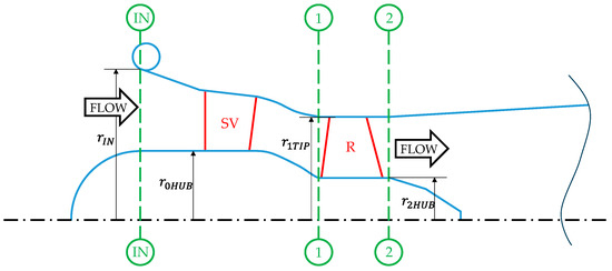
Figure 1.
Propeller turbine and rotor regulating turbine meridional section (only stay vane distributor): IN = turbine inlet section, 1 = rotor inlet section, 2 = rotor outlet section.
The design operating parameters of the turbine obtained by the final RANS simulation are
To make turbine flow rate regulation possible, the above-described propeller turbine (single point operating turbine) is modified by allowing rotor blade regulation by means of blade stagger angle variation (rotor regulation) or, alternatively, by adding regulating guide vanes (distributor regulation). Therefore, for rotor regulation, the turbine is geometrically equal to the propeller turbine (Figure 1). Distributor regulation has previously been analyzed by the authors [12]. For distributor regulation, the shape of the meridional channel is kept unchanged, but it is necessary to axially extend the initial cylindrical part of the channel to house the two stator rows, stay vanes (SVs) and guide vanes (GVs) (Figure 2), in spite of the original fixed single stator row (stay vanes). Of course, the stay vanes for the two configurations are different since in the rotor regulation case, the rotor inlet flow distribution needs to be created only by the stay vane row, while in the distributor regulation case, it is the two-vane row that creates the inlet rotor flow distribution. In other words, at the design operating point, the two different distributors should provide the same tangential velocity distribution at the rotor inlet.
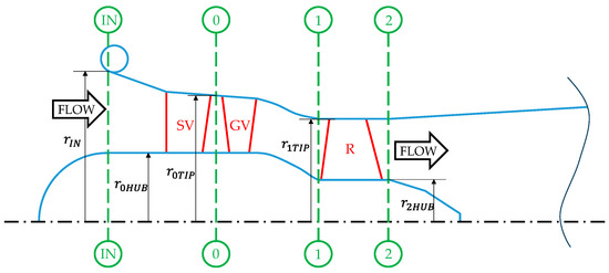
Figure 2.
Distributor regulating turbine meridional section: IN = turbine inlet section, 0 = guide vane inlet section, 1 = rotor inlet section, 2 = rotor outlet section.
3. Turbine Mean Line Design and Off-Design Analysis
Assuming that for both regulating turbines, the rotor tip diameter is and therotational speed is , from the design operating parameters and previously defined, the resulting design flow rate is and the design net head is For the present optimized turbine prototype, the hub diameter is The main turbine geometrical parameters are reported in Table 1.

Table 1.
Propeller turbine’s main geometrical parameters.
The mean line blade velocity is , indicated in the following as for simplicity.
3.1. Mean Line Basic Equations
The 1D mean line design and analysis of the axial turbine are developed by introducing the turbomachinery fundamental coefficients and .
is the mean line flow coefficient, indicated in the following as for simplicity, which introduces the continuity equation in the analysis:
where is the axial velocity component, and is the turbine rotor frontal area.
is the head coefficient indicated in the following as for simplicity, which is used to introduce the energy equation in the analysis:
The term represents the specific power extracted by the turbine rotor from the fluid and can be defined as work, . The term is the hydraulic turbine efficiency. The Eulerian work equation calculates the work exchanged by the turbine rotor as the variation in the tangential momentum of the fluid:
where are the tangential absolute velocity components at the inlet and exit of the turbine rotor.
Considering the turbomachinery fundamental kinematic relationships, which correlate absolute and relative flow velocities in the sections upstream and downstream of the turbine rotor and , and introducing the flow absolute angles and flow relative angles , it is possible to determine the velocity components and the angles of the flow in the absolute and relative frames of reference, which are congruent with the assigned turbine fundamental parameters , and .
Passing from a relative to absolute frame of reference:
At the rotor inlet section:
and
At the rotor exit section:
and
From Equation (5), the inlet and exit angles in the absolute and relative frames can be correlated:
3.2. Mean Line Analysis at the Design Point
The axial velocities at the inlet and exit of the rotor blades can be calculated from the design flow rate and the hub and tip diameters of the rotor, assuming a constant radial distribution. The resulting axial velocity at the design point is . For the present case, the turbine efficiency η is assumed to be .
Moreover, the mean line blade velocity is ; consequently, the mean line flow coefficient φ and the mean line head coefficient assume the following values:
To calculate the fundamental angles of the stage, i.e., the stator vane exit angle , rotor blade inlet angle , and rotor blade exit angle , which in this simplified analysis are assumed to coincide with the flow angles in the design condition, one more condition should be added. For a single-stage turbine, the additional condition is a zero absolute tangential velocity component at the rotor exit at the design point to minimize the kinetic energy loss at the turbine exit . By applying Equation (5) and the other equations in sequence, reported in the previous paragraph, we obtain
Figure 3 reports the velocity triangles at the inlet and exit of the rotor in the design condition. The velocity triangles are the same, independently of the distributor assembly type (stay vane and guide vane distributor for regulation by guide vane stagger angle variation, and distributor with only longer stay vanes for regulation by rotor blade stagger angle variation).
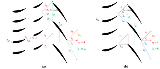
Figure 3.
Velocity triangles at a nominal operating point for the guide vane (a) and rotor (b) regulation strategies.
3.3. Off-Design Mean Line Analysis
In the following off-design analysis, we indicate , and for simplicity.
Under a constant net head, the turbine off-design operation consists of the regulation of the flow rate operated by varying the profile stagger angle (opening or closing) of the regulating element, which can be the guide vane row or the rotor blade row, depending on the type of regulation adopted.
The flow rate during regulation () can be expressed as a fraction (smaller or larger than 1) of the flow rate at the design point ():
Since is proportional to , . Consequently,
and
A constant net head during the off-design operations implies that . Therefore,
Equation (5) imposes a strong link between the two tangential absolute velocity components in any operating condition.
3.4. Regulation by Guide Vane Stagger Angle Variation
A fixed rotor blade stagger angle implies and . The residual absolute tangential velocity component at the rotor exit, , can be evaluated from Equation (7) with :
Then, and from Equation (5),
From and , the flow angle is obtained.
In the simplified approach here presented, the guide vane exit flow angle is assumed to be equal to the guide vane geometrical exit angle ( and, therefore, from the guide vane geometry, the guide vane stagger angle (or the guide vane opening angle with respect to fully closed guide vane ring) is also determined, which represents the fundamental parameter for the distributor regulation.
From the guide vane geometry, the guide vane geometrical inlet angle is also determined, and if the stay vane exit angle has been fixed in the design procedure ( in the present case), the guide vane incidence angle (which the profile losses of the guide vane during off-design operation are associated with) can be determined: .
Finally, from the absolute rotor blade inlet tangential velocity , the relative rotor blade inlet tangential velocity and the relative rotor blade inlet flow angle can be immediately determined. From the latter, the rotor blade incidence angle (which the profile losses of the rotor blade during off-design operation are associated with) can also be determined: .
The analysis of regulation by guide vane stagger angle variation can then be carried out over the complete range of operating conditions with .
Examples of velocity triangles for the regulation by guide vane stagger angle variation for a reduced flow rate condition 1) and increased flow rate ( are reported in [12].
3.5. Regulation by Rotor Blade Stagger Angle Variation
A fixed exit stator angle implies and
with geometrical blade profile deflection.
If the distributor exit angle is fixed, the off-design condition implies that the rotor inlet absolute tangential velocity component is fixed . If the turbine operates at a constant net head, the condition of Equation (17) is imposed and, therefore, the value of the absolute tangential velocity component at the rotor blade exit is fixed, too. Thus, it will be the blade stagger angle variation, related to the blade exit angle , that really determines the imposed axial velocity (and flow rate) condition. Then, it should be
and or . Then, from Equation (13) and the simplified condition of null exit angle deviation, the inlet blade angle is determined for the rotor blade opening, which is defined by , and from this value, the rotor blade incidence angle (which the profile losses of the rotor blade during off-design operation are associated with) can also be determined: , where .
An analysis of regulation by rotor blade stagger angle variation can be carried out over the complete range of operating conditions with .
Typical velocity triangles are depicted in Figure 4 for (reduced flow rate) and in Figure 5 for (increased flow rate), where the green rotor blades represent the design condition whereas the black ones stand for an off-design condition.
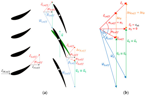
Figure 4.
(a) Velocity triangles at with rotor regulation; (b) comparison between off-design and design velocity triangles.
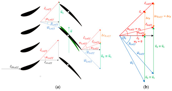
Figure 5.
(a) Velocity triangles at with rotor regulation; (b) comparison between off-design and design velocity triangles.
3.6. Off-Design Loss Evaluation
In principle, 1D mean line analysis of a turbine stage involves only profile losses, which can be evaluated by correlations. Of course, in order to improve the efficiency estimate of a stage, other 3D additional losses like end-wall and secondary losses, intake, and diffuser losses can be also roughly estimated, again, by means of empirical correlations. In off-design conditions, the profile losses tend to become the most relevant due to important values of the flow incidence angles. Furthermore, also relevant off-design kinetic energy losses occur, associated with large residual absolute velocity tangential components at the rotor exit in off-design conditions.
In this first part, the present study is focused on the comparison of the two different regulating concepts and on the explanation of the differences, whereas the accurate efficiency estimation of the off-design operation of the turbines is not an objective. Therefore, the off-design loss model adopted is the simpler one based only on profile and kinetic energy losses. A more accurate evaluation of losses and off-design turbine efficiency curves is more properly targeted in the second part of the present paper dealing with the 3D CFD simulation of the two turbines.
For the evaluation of profile losses, the classical Ainley and Mathieson correlation [14] is adopted, which is based on a loss coefficient defined using the profile exit velocity (which stands for for the stator vanes and for the rotor blades). In off-design conditions, a multiplying coefficient related to the incidence angle is introduced:
is the Ainley and Mathieson profile loss coefficient in the design condition. From Figure 4 of the Ainley and Mathieson paper [14], the base coefficient is assumed to be 0.04 for rotor profiles and distributor long stay vanes (rotor regulation), and 0.02 for stay vanes and guide vanes for distributor regulation. is the incidence angle coefficient evaluated by fitting the curve of Figure 6 of the same paper.
In the design condition, both turbine distributor configurations (longer stay vanes without guide vanes and a double row of shorter stay vanes followed by guide vanes) nominally have the same profile losses since the incidence angles are zero for both the rotor and stator. In off-design conditions, the profile losses become significantly different for the two configurations since the incidence angles are different for the rotors and especially different for the stators, as the fixed stay vane configuration, without guide vanes, does not suffer from the incidence angle effect.
The off-design kinetic energy losses can be directly calculated by the residual absolute velocity tangential component at the rotor exit, as
where, for regulation by guide vane stagger angle variation, can be evaluated from Equation (11) as
while regulation by rotor vane stagger angle variation can be evaluated from Equation (14):
In the present paper, both profile and kinetic energy losses are normalized by the net head to make the normalized loss coefficient:
suitable for a direct estimate of the turbine efficiency:
3.7. Comparison of Regulations by Guide Vane Angle Variation and Rotor Blade Angle Variation
The mean line off-design flow distributions (velocity triangles) upstream and downstream of the rotor are remarkably different for the two strategies of regulation.
In reality, what remains equal for the two turbine configurations is the axial velocity (which represents the height of the velocity triangles), since during flow rate regulation, is imposed, and the difference between the tangential components of the absolute velocities is imposed by , since the net head remains constant.
Conceptually, in any case, the regulation of the flow rate must be obtained by variation in the throat of a row of profiles, the guide vane row in one case and the rotor blade row in the other case.
The throat can be expressed, for the first case, as , and for the second case, as , where and are the circumferential distances between the trailing edges of the guide vanes and of the rotor blades, respectively. At the guide vane exit, the flow angle is approximately 30 degrees, while at the rotor blade exit, the flow angle is approximately −60 degrees; therefore, a variation of +/−5 degrees of the two angles, for the two cases, determines a variation of about 10% for the guide vane row throat and a variation of about 30% for the rotor blade row throat. Therefore, the mechanism of flow rate variation is more effective for rotor regulation.
Another fundamental difference is due, for the case of regulation by guide vane stagger angle variation, to the condition of fixed rotor exit angle . When the axial velocity varies with respect to the design condition (, the fixed induces a significant variation of , which, added to the blade velocity u, results in a relevant co-rotating absolute tangential velocity component for and in a relevant counter-rotating absolute tangential velocity component for (Figure 6a).
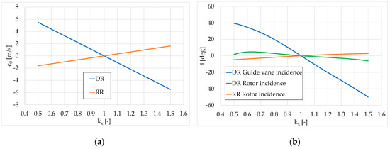
Figure 6.
Rotor exit absolute tangential velocity component (a) and incidence angle (b) as a function of flow rate variation parameter (DR = distributor regulation and RR = rotor regulation).
Apart from the production of large tangential kinetic energy losses at the lowest and largest flow rates, the co-rotating tangential components need to be compensated for with a further generation of tangential angular momentum at the guide vane exit for (requiring guide vane closing), while the counter-rotating residual velocities at the rotor exit need to be compensated for with a decrease in tangential angular momentum at the guide vane exit for (requiring guide vane opening). Consequently, the guide vane opening variation becomes large and the incidence angle on the guide vane inlet (Figure 6b), and associated off-design losses, are large as well (Figure 7a). Consequently, the opening variation needs to be limited for excessive loss increase reasons and also for kinematic reasons.
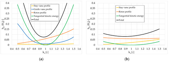
Figure 7.
Normalized losses’ contributions as a function of flow rate variation parameter for distributor regulation (a) and rotor regulation (b).
For the regulation with rotor blade stagger angle variation, the rotor blade opening variation with respect to the design condition, necessary for obtaining the desired flow rate regulation, is much lower (approximately three times lower), and that results in an attenuation of co-rotating and counter-rotating absolute tangential velocity components (Figure 6a), due to the amplifying effect of the variation in on the relative tangential velocity component , even for small variations in the angle (with the flow angle in the design condition being large, at approximately −60 degrees).
This effect reduces the tangential kinetic energy losses at the rotor exit (Figure 7) and the incidence angle on the rotor (Figure 6b), which, in turn, reduces the off-design rotor blade profile losses as well (Figure 7b).
Furthermore, for regulation with only rotor blade stagger angle variation, the stay vane incidence angle remains null for any flow rate variation and, therefore, the loss coefficient remains that of the design condition, and the stay vane losses remain low over the whole range of flow rate regulation (Figure 7b).
The off-design mean line analysis shows that both incidence and tangential kinetic energy losses, and therefore the mean line total losses, are much lower for the regulation by rotor stagger angle variation (Figure 7b) when compared with those resulting from guide vane stagger angle variation (Figure 7a). The 1D analysis is conceptual but limited to the mean line and furthermore the loss evaluation is limited to only two types of losses. Moreover, the profile loss evaluation, based on empirical correlations, is used in the most simplified manner. Thus, even if the conceptual character of these results is expected to remain valid, a fully 3D CFD analysis must be carried out, as is presented in the following part of the paper, to evaluate the differences in the two regulation strategies by using more realistic modeling that allows more accurate results.
4. Turbine 3D CFD Simulation
A 3D steady-state RANS analysis of the turbine was conducted using the widely utilized Cadence CFD software [15], renowned for its efficacy in turbomachinery applications [16,17,18] and also in very complicated environments, as demonstrated by previous authors’ work [19].
The machine geometry was defined using the Autoblade parametric geometry generator, facilitating easy modification of blade profiles within the simulation software through a limited set of geometric parameters.
Two different geometries were generated for simulating the flow in the turbine equipped with the two different regulation schemes (distributor regulation and rotor regulation). It is essential to note that distributor regulation necessitates that the turbine stage is made of three blade rows—two stators (with structural and regulation functions, respectively) and one rotor. Conversely, rotor regulation requires only two blade rows—a stator for structural support and flow deflection, and a rotor with a variable blade stagger angle. Adjustments to the geometry for the regulating rows were made by means of the parametric geometry generation software, modifying the constructive angles of the rows to account for stagger angle variations.
Thus, for each tested operating condition, a distinct machine geometry was developed, accompanied by an appropriate computational mesh ensuring a high grid quality, since the shape of the three-dimensional domain varied in response to the row configurations. In Figure 8 and Figure 9, the 3D renderings of the low head axial flow hydraulic turbine for the two different regulating strategies (distributor regulation and rotor regulation, respectively) are represented for minimum, nominal, and maximum flow rate configurations.

Figure 8.
Three-dimensional rendering of the hydraulic turbine for the distributor regulation strategy: minimum opening (a), nominal opening (b) and maximum opening (c).

Figure 9.
Three-dimensional rendering of the hydraulic turbine for the rotor regulation strategy: minimum opening (a), nominal opening (b) and maximum opening (c).
The computational mesh was generated using Autogrid 5 by Cadence and consisted of approximately 5 million nodes for the three-row configuration. A multi-block approach with an O-4-H mesh topology was applied for stay vane, guide vane (where applicable), and rotor rows. For the downstream axial draft tube, a mesh capable of managing singularity conditions on the axis was utilized.
Each row was simulated with a single blade passage, and information transfer from the stator frame to the rotor frame was facilitated using a mixing plane approach. In cases involving distributor regulation, the stator rows were configured in tandem to maintain proper alignment of rows in the tangential direction, hence influencing the position of wakes.
Grid independence was ensured by assessing three different mesh densities for the nominal configuration and evaluating the turbine key operational parameters: net head and hydraulic efficiency. The analysis is reported in [11]. Figure 10 illustrates the mesh configuration for the distributor regulation prototype (three-row turbine stage).
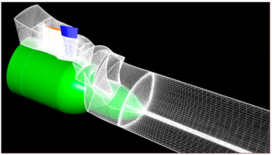
Figure 10.
Three-dimensional mesh configuration for distributor regulation.
Spatial discretization of the equations employs a cell-centered control volume approach, while time discretization employs a multistage Runge–Kutta scheme with local time stepping, coupled with the multigrid technique [15].
For turbulence modeling, considering a fully turbulent flow condition imposed by the high Reynolds number, equal to about 2.7 million based on axial velocity and the rotor blade chord, the Spalart–Allmaras one-equation model [20] is employed, renowned for its ability to offer a straightforward yet reliable assessment of turbulence effects in hydraulic applications [21,22,23]. The height of the first cell near solid walls in each row is adjusted to achieve a non-dimensional wall coordinate (y+) of approximately 1.
In the inlet section, boundary conditions are set for the mass flow rate, static temperature, and flow direction, while in the outlet section, the averaged static pressure imposed by the hydrostatic head at the exit is specified. Turbulent viscosity boundary conditions at the inlet are determined based on the assumed turbulence intensity (3%) and characteristic length scale (rotor blade chord), utilizing established formulae [15].
Given the solver reliance on a density-based approach, the Hakimi preconditioning model [24] is employed to address the incompressible flow condition.
For each regulation strategy, simulations were conducted across various operating conditions in a sequential manner. The simulation process entails the following steps:
- Stagger angles of the regulating rows are selected based on the outcomes derived from the 1D analysis.
- The calculation proceeds iteratively until convergence is achieved. The total pressure drop across the machine serves as a metric for assessing the net head value.
- If the obtained net head deviates from the target value for the actual application (Hn = 4 m), adjustments are made to the inlet mass flow rate. Specifically, if the obtained net head is lower than the design value, the inlet mass flow rate is increased; conversely, if the obtained net head exceeds the design value, the inlet mass flow rate is reduced.
- The iterative process continues until the net head value matches the predetermined value for the actual operating condition.
5. Off-Design CFD Simulation Results
Results from the extensive off-design 3D CFD simulation of the low head turbine prototype are shown and analyzed in the following paragraphs. The results are given for the case of guide vane regulation and for rotor regulation for different flow rates under a fixed head.
5.1. Velocity Component Radial Distributions at the Rotor Inlet and Outlet
The three-dimensional characteristics of the flow at the inlet and exit of the rotor can be understood by examining the spanwise distribution of the circumferentially averaged flow velocity components. The radial gradients of axial velocity, angular momentum, and work exchange as well as entropy and centrifugal acceleration related to meridional streamline curvature are in equilibrium in the radial direction.
At design point, the axial velocity at the rotor inlet is not constant in the radial direction due to the curvature of the flow channel in the meridional plane, resulting in a larger meridional velocity component near the blade tip (Figure 11 and Figure 12). The rotor tends to invert this trend by increasing the meridional velocity component at the root in the rotor blade exit section. This effect is stronger when the flow rate increases for the case of distributor regulation (Figure 11) while it becomes very strong when the flow rate decreases for the rotor regulation case (Figure 12). For rotor regulation, this effect of increasing the velocity at the blade root and decreasing it at the tip at a low flow rate is related to the large rotor blade twisting due to the nearly free vortex design of the blade. Indeed, the closing of the blade has a different effect on the tip section of throat characterized by an exit angle of about −74 deg than on the hub section of throat characterized by an exit angle of about −48 deg in the design condition.
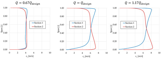
Figure 11.
Meridional velocity spanwise distribution upstream and downstream of the rotor row for distributor regulation at three different flow rates.
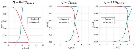
Figure 12.
Meridional velocity spanwise distribution upstream and downstream of the rotor row for rotor regulation at three different flow rates.
The turbine was preliminary designed by using the NISRE (Non-Isentropic Simple Radial Equilibrium) equation, as proposed in [25], with the intent of designing the turbine on the basis of free vortex flow or, in other words, imposing constant work exchange in the radial direction. The design, afterwards, underwent an optimization process aimed at maximizing the total-to-total efficiency and minimizing the absolute tangential velocity components at the exit [11]. In any case, Figure 13 and Figure 14 show a spanwise distribution of the difference in tangential absolute velocity components at the blade inlet and exit in line with the constant work exchange design condition, that is, ( approximately inversely proportional to u. That is certainly true for the design operating point. Conversely in off-design conditions, especially for the case of distributor regulation at a low flow rate, the work is reduced at the rotor tip (Figure 13), and that influences the axial velocity distribution by accelerating the flow at the tip, hence resulting in a more constant spanwise axial velocity component distribution (Figure 11, left).
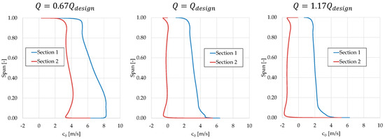
Figure 13.
Absolute tangential velocity spanwise distribution upstream and downstream of the rotor row for distributor regulation at three different flow rates.
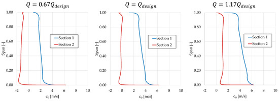
Figure 14.
Absolute tangential velocity spanwise distribution upstream and downstream of the rotor row for rotor regulation at three different flow rates.
Figure 13 and Figure 14 show how the two regulation strategies operate on the absolute tangential velocities at the rotor inlet and outlet to guarantee the condition of a constant head (i.e., constant tangential absolute velocity component difference) for different flow rates. The result is an opposite tendency of how the two regulation strategies affect the exit tangential velocity direction.
For distributor regulation, the rotor exit absolute tangential velocity is imposed by the constant angle condition in relation to the axial velocity variation associated with the flow rate. Therefore, co-rotating (positive) residual tangential velocity components at a reduced flow rate and counter-rotating (negative) residual tangential velocity components at an increased flow rate are induced. The guide vanes are closed or opened in a way to compensate for this by increasing or by decreasing the rotor inlet absolute tangential velocity component.
The opposite happens with the rotor regulation. The rotor inlet absolute tangential velocity decreases when the flow rate decreases and increases when the flow rate increases because of the constant angle condition imposed by the fixed stator. The rotor must compensate for this fact by inducing at the rotor outlet a counter-rotating (negative) absolute tangential velocity at low flow rate and a co-rotating (positive) absolute tangential velocity at a high flow rate.
5.2. Normalized Entropy Loss
In adiabatic thermodynamic transformations such as those of turbomachinery flows, the increase in entropy is exclusively due to transformation irreversibility; therefore, all the fluid dynamic losses can be directly evaluated by entropy generation according to [26]. In the present paper, the local losses associated with entropy increase from the turbine inlet section to the rotor exit section () are made non-dimensional by the potential specific energy ( according to Equation (17), where is the specific entropy local variation in Section 2 with respect to the turbine inlet section value.
The distributions of the normalized specific entropy in Section 2 are shown in Figure 15 (distributor regulation) and Figure 16 (rotor regulation), as color plots, for three turbine operating points: design (), low (), and high ( flow rates.

Figure 15.
Normalized entropy loss contribution at the rotor outlet for distributor regulation at three different flow rates.

Figure 16.
Normalized entropy loss contribution at the rotor outlet for rotor regulation at three different flow rates.
The structure of the entropy distribution in Section 2, downstream of the rotor, is similar for the design and high-flow-rate operating conditions, for both stator and rotor regulations. The entropy distribution shows the traces of the four blades because of energy dissipation within the blade boundary layers. The rotation is clockwise when seen from downstream. The suction side boundary layers are more intense, and entropy is produced mainly in the interaction region between the suction side blade tip and the rotor casing. With a high flow rate for distributor regulation, it seems that entropy losses increase mainly because of the increase in the relative velocity in the rotor. With a high flow rate for rotor distribution, the blade wake traces become straighter because the decrease in the blade stagger angle is more effective in reducing the relative tangential velocity and producing co-rotating absolute tangential velocity components at the blade tip sections, which have larger exit angles. At a reduced flow rate, a larger increase in the entropy production and a change in the structure of the distribution of this quantity can be observed. In this condition, especially for the distributor regulation, the entropy production also affects the region in the blade passages to a larger extent, because of distributor loss increase due to larger values of flow incidence on the guide vanes at a reduced flow rate.
For rotor regulation at a reduced flow rate, the change in structure is the most striking aspect. In this operating condition, the entropy traces identifying the wakes are strongly slipping backward at the tip because the stagger angle increase largely influences the tip sections, inducing larger counter-rotating absolute tangential velocities near the tip, due to the blade exit twist.
5.3. Normalized Tangential Kinetic Energy Loss
The specific entropy generation includes all the internal fluid dynamic losses and can be used for the total-to-total efficiency evaluation. On the contrary, the kinetic energy losses due to residual exit velocity are not included. To obtain the real turbine efficiency, also these losses should be evaluated and added to the energy budget. Usually, since the exit axial velocity is inherently associated with the flow rate through the turbine, this component is not included in the kinetic energy losses attributed to the turbine power conversion and its effect is normally included as a reduction in the power plant net head. On the contrary, the kinetic energy associated with the residual tangential velocity component at the rotor exit, which can become relevant in off-design operation, is a loss to be attributed to the turbine energy budget and shall be added to the specific entropy losses to evaluate the real turbine efficiency. Thus, the local tangential kinetic energy at the rotor exit () is made non-dimensional by the potential specific energy ( according to Equation (17), as shown in Figure 17 and Figure 18 as color plots. Please observe that to highlight the structure of the distribution of this quantity, and also for comparison with the entropy generated losses, the scale has been reduced with respect to the normalized entropy loss color plot scale.

Figure 17.
Normalized tangential kinetic energy loss contribution at the rotor outlet for distributor regulation at three different flow rates.

Figure 18.
Normalized tangential kinetic energy loss contribution at the rotor outlet for rotor regulation at three different flow rates.
As expected, the tangential kinetic energy loss is nearly 0 at the design point, except in the thin blade wakes, where, theoretically, in the wake center, the relative velocity tends to zero and the absolute tangential velocity component, consequently, tends to u. This is a local effect, which does not significantly affect the loss budget since in the wake region, the axial velocity component tends to zero and, therefore, the loss content tends to zero. On the contrary, the tangential kinetic energy becomes relevant in the off-design condition both at increased and at reduced flow rates. The effect is much more relevant for the distributor regulation strategy, where the variation in the axial velocity in off-design operation, due to a fixed blade exit angle, directly results in a proportional rotor exit tangential velocity, while this effect is attenuated for the rotor regulation strategy due to the positive compensative effect of the rotor blade stagger angle variation. In off-design conditions, for distributor regulation, the residual tangential kinetic energy increases in the inter-passage regions; hence, its effect due to the axial velocity transport becomes relevant to the energy loss budget.
5.4. Main Loss Contributions
To better understand the effects of the two fundamental loss mechanisms, two global loss parameters, related to the generation of entropy and to the residual tangential kinetic energy at the rotor exit, are defined in agreement with Equation (17):
where is the specific global entropy variation between the turbine inlet section and the rotor exit section, and () is the global tangential kinetic energy in the rotor exit section. The global terms of Equations (19) and (20) are obtained through the mass weighted average of local values.
The two global loss parameters are displayed and compared by means of the histograms presented in Figure 19, where the turbine efficiency as a complement to one of the two main loss contributions is highlighted. The histograms show that the entropy losses are larger than the tangential kinetic energy losses, except at the low flow rate extremity for the distributor regulation, but their variations are limited in the flow rate range considered. The tangential kinetic energy losses, on the contrary, especially for distributor regulation, start from zero in the design condition and display more significant variations with the flow rate. Above all, the comparison of the histograms highlights that the rotor regulation strategy is more effective in terms of attenuation of both loss mechanisms in off-design operating conditions and that, at the extreme flow rate values considered for this comparison, there are relevant differences for the turbine efficiency evaluated by means of this CFD analysis: approximately 8 percentage points for 1.17 and 15 percentage points for .
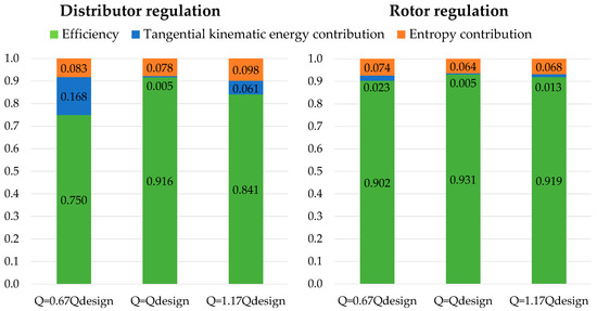
Figure 19.
Comparison of main loss contributions and efficiency levels for three different flow rates for distributor regulation and rotor regulation strategies.
5.5. Turbine Global Operation Parameters
From the local fluid dynamic quantities provided by the design and off-design CFD simulations, the three main turbine operation engineering parameters can be evaluated, namely, efficiency curves, output power curves, and opening curves of the regulating rows (guide vanes or rotor blades), which allow the desired flow rate regulation.
5.5.1. Efficiency Curves
Figure 20 reports the curves of the efficiency normalized with respect to the maximum value in the design condition as a function of the flow rate fraction for the stator and rotor regulation strategies. The numbers in squares indicate the values of the stagger angle variation with respect to the design opening of the regulating rows (guide vanes and rotor blades, respectively).
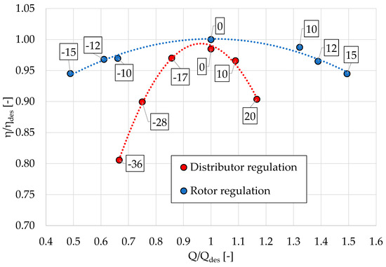
Figure 20.
Normalized efficiency curves versus fraction of design flow rate for distributor regulation and rotor regulation.
These results indicate that the rotor regulation strategy allows for larger efficiencies all over the turbine operation range, with values that are larger than 10 percentage points at the extremities of the distributor regulation curve. Because of the larger efficiency drop (assuming, for instance, a limiting value for the normalized turbine efficiency of 0.9 of the design value), the operating range of the distributor regulation strategy is limited to a range spanning approximately from 0.75 to 1.15. When applying the same efficiency drop limitation, the rotor regulation strategy displays a range of acceptable operation spanning approximately from 0.4 to 1.55.
5.5.2. Output Power Curves
The effect of turbine efficiency on the turbine’s useful power output is highlighted in Figure 21. The numbers reported in squares are the values of the normalized turbine efficiency.
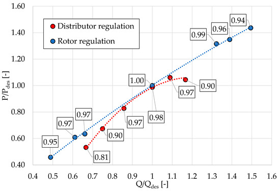
Figure 21.
Normalized power curves versus fraction of design flow rate for distributor regulation and rotor regulation.
The positive effect of rotor regulation in comparison to distributor regulation results in a larger turbine power output provided all over the complete flow rate range, which, furthermore, is much more extended for rotor regulation. Consequently, as a final practical result, the regulation choice has a significant impact on the overall energy conversion evaluated in the turbine yearly operating period, with an expected energy production of the rotor regulation turbine that can be larger than 10 percent, depending on the flow rate duration curve of the power plant.
5.5.3. Stagger Angle Regulation Curves
Figure 22 shows that the rotor regulation strategy is more effective in regulating the turbine flow rate than the distributor regulation strategy because, to obtain the same mass flow rate variation, a much lower stagger angle variation is needed in the former case as compared with the latter case. This is mainly due to the different inclinations of the throats of the regulating rows in the two cases, as previously explained. This fact has an important impact on the strokes of the regulation actuation mechanisms for the two cases. Another important difference related to this aspect of the regulation process is the limitations on opening (for the guide vanes) and closing (for the rotor blades) angles. Taking the curves of Figure 22 as a reference and assuming a design guide vane opening angle of 30 deg (taken with respect to the axial direction), from the distributor regulation curve of Figure 22, it can be seen that there is an extreme limitation on the operational range on the large flow rate side, represented by the condition of full opening with a 0-degree guide vane exit angle ( = +30 deg in figure). Conversely, for rotor regulation, due to the large value of the exit blade angle at the tip (of the order of −70 deg), the limitation is that the blade closing angle that should not cause the tip blade profile to enter a reverse flow condition. With reference to Figure 22, this limitation should occur at around 0.3 when the blade closure reaches about = −20 deg.
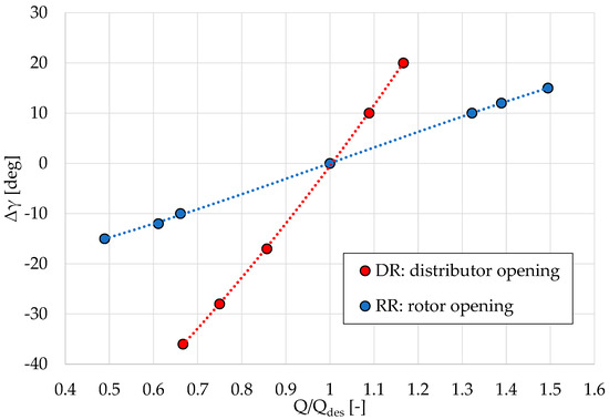
Figure 22.
Opening angle laws of the regulating rows as a function of the normalized flow rate for distributor regulation and rotor regulation.
6. Conclusions
Two different regulation strategies for low head hydraulic turbines of limited power have been studied in detail, namely, regulation by variation in the stagger angle of the guide vane row of the two-row distributor and regulation by variation in the stagger angle of the rotor blade row with a fixed single row distributor.
This study was conducted with reference to a high-specific-speed optimized prototype of a tubular axial turbine (TAT) designed by the authors. The flow in design and off-design operation conditions, under a constant net head and variable flow rate, were studied using both a classic 1D mean line flow approach based on the fundamental turbomachinery equations, basic profile loss correlations, and direct tangential kinetic energy loss evaluation and using an approach of advanced 3D RANS CFD simulations.
The 1D mean line approach is used for deeply understanding the conceptual fluid dynamic aspects involved in the two different regulation approaches, identifying the loss-generation mechanisms in off-design operation, and providing a preliminary evaluation of the effects of the two different regulation processes on basic energy losses and regulation strategies overall performance.
The detailed and systematic CFD simulation of the off-design turbine flow field, which includes any loss-generation mechanisms of the 3D turbine environment, provides detailed fluid dynamic results that describe and interpret the real off-design turbine operation with an imposed net head and varying flow rate. The results explain and quantify the different performances of the two distinct regulation strategies.
Regulation by variation in the rotor blade stagger angle is better than regulation by variation in the guide vane stagger angle in terms of both effectiveness (larger flow rate sensitivity to stagger angle variation) and turbine operating efficiency (lower off-design losses).
The larger sensitivity of rotor regulation as compared with distributor regulation is related to the different exit angles of the two regulating rows in the design condition. The guide vane design exit angle is of the order of 30 deg with respect to the axial direction while the average rotor blade exit angle is of the order of −60 deg or more. Therefore, a small stagger angle variation has a greater effect on the throat variation, and thus on the flow rate, for the rotor regulating row with respect to the throat variation in the distributor regulating row. That impacts directly on the reduction in the stroke of the regulation mechanical actuator to achieve the desired range of flow rate variation and also has an indirect important effect on the loss-generation mechanisms.
Indeed, the larger stagger angle variation for distributor regulation, necessary to obtain the same targeted flow rate variation, results in larger incidence angles for both guide vanes and rotor blades and enhancement of secondary flows, which induce larger off-design profile and secondary flow losses as compared with the case of rotor regulation, which, on the contrary, requires lower stagger angle variation.
An explanation based on the exit angles of the regulating rows is relevant to understand why distributor regulation produces much larger tangential kinetic energy losses in off-design operation. In this case of a fixed rotor exit angle, the axial velocity variations, proportional to the targeted flow rate variations, are amplified by the tangent of the exit angle (of the order of −60 deg or more), creating large exit tangential velocity components and therefore large tangential kinetic energy losses. On the contrary, the rotor regulation strategy relies on the fact that the rotor stagger angle variations compensate for the variations in the inlet tangential velocity, which are produced by the invariability of the stator angle, with adequate co-rotating or counter-rotating rotor exit absolute tangential velocities, to comply with the work value fixed by the constant head condition. Since the stator exit angle is of the order of 30 deg, the variations in inlet tangential velocity due to the axial velocity variations proportional to flow rates are attenuated by the tangent of the exit stator angle. Consequently, the tangential kinetic energy exit losses have moderate values for rotor regulation.
A lower level of off-design losses for rotor regulation strategy positively impacts on the turbine efficiency all across the flow rate operating range, with values of the turbine efficiencies larger than 10 percentage points toward the extremities of the operating range. Due to these loss differences, especially in severe off-design conditions, and due to the mechanical limitations required to achieve extreme targeted flow rate variations, the turbine operating range for the case of rotor regulation is much wider than that for the case of distributor regulation. The operating range can span from 0.4 to 1.55 for the rotor regulation strategy while it is more limited (from 0.65 to 1.15) for the distributor regulation strategy. The more extended flow rate range of operation and larger turbine efficiency result in a considerably larger yearly energy production in relation to the yearly discharge duration curve of the power plant.
A further practical advantage of the rotor regulation strategy is the reduction in one row of vanes (over the three) for the turbine stage, which results in a lower turbine weight and cost and, furthermore, in a shorter axial length for the turbine. The latter has also an important positive effect on the shaft-bearing assembly due to the greater stiffness and lower weight of the shaft.
From the present analysis, the only drawback that seems to affect the rotor in respect to distributor regulation is the more complex mechanism for rotor blade stagger angle variation, which must be installed directly within the hub and must be actuated during turbine operation and, thus, with the hub in rotation.
Author Contributions
Conceptualization, D.B., F.S., M.U. and P.Z.; methodology, D.B., F.S., M.U. and P.Z.; software, D.B. and F.S.; validation, investigation and data curation: D.B. and F.S.; writing—original draft: D.B., F.S., M.U. and P.Z.; writing, review and editing, D.B., F.S., M.U. and P.Z.; supervision, D.B., F.S., M.U. and P.Z. All authors have read and agreed to the published version of the manuscript.
Funding
This research received no external funding.
Data Availability Statement
The original contributions presented in the study are included in the article, further inquiries can be directed to the corresponding author.
Conflicts of Interest
The authors declare no conflicts of interest.
Nomenclature
| Area | Subscripts | ||
| Absolute velocity | Distributor inlet section | ||
| Diameter | Rotor inlet section | ||
| Gravitational acceleration | Rotor outlet section | ||
| Lost head | Rotor blade | ||
| Net head | Design value | ||
| Incidence angle | Guide vane | ||
| Tangential unit vector | Blade hub | ||
| Flow rate coefficient | Turbine inlet section | ||
| Rotational speed | Tangential kinetic energy | ||
| Specific speed | At mean line | ||
| Turbine useful power | Off-design | ||
| Volumetric flow rate | Profile | ||
| Radial coordinate or radius | Rotor | ||
| Entropy | Entropy | ||
| Temperature | Blade tip | ||
| Peripheral velocity | Total | ||
| Relative velocity | Vane | ||
| Work exchange | Axial | ||
| Non-dimensional wall coordinate | Tangential | ||
| Incidence angle coefficient | |||
| Base profile loss coefficient | |||
| Greek | Acronyms | ||
| Absolute flow angle | Artificial neural network | ||
| Relative flow angle | Computational Fluid Dynamics | ||
| Stagger angle | Distributor regulation | ||
| Turbine hydraulic efficiency | Guide vane | ||
| Tangential coordinate | Non-isentropic radial equilibrium | ||
| Flow coefficient | Reynolds-averaged Navier–Stokes | ||
| Work coefficient | Rotor regulation | ||
| Angular velocity | Stay vane | ||
| Tubular axial turbine | |||
References
- REN21. Renewables 2023 Global Status Report Collection. 2023.
- Farfan, J.; Breyer, C. Aging of european power plant infrastructure as an opportunity to evolve towards sustainability. Int. J. Hydrogen Energy 2017, 42, 18081–18091. [Google Scholar] [CrossRef]
- Kougias, I.; Aggidis, G.; Avellan, F.; Deniz, S.; Lundin, U.; Moro, A.; Muntean, S.; Novara, D.; Perez-Diaz, J.; Quaranta, E.; et al. Analysis of emerging technologies in the hydropower sector. Renew. Sustain. Energy Rev. 2019, 113, 109257. [Google Scholar] [CrossRef]
- Sinagra, M.; Picone, C.; Picone, P.; Aricò, C.; Tucciarelli, T.; Ramos, H.M. Low-Head Hydropower for Energy Recovery in Wastewater Systems. Water 2022, 14, 1649. [Google Scholar] [CrossRef]
- Quaranta, E.; Bahreini, A.; Riasi, A.; Revelli, R. The Very Low Head Turbine for hydropower generation in existing hydraulic infrastructures: State of the art and future challenges. Sustain. Energy Technol. Assess. 2022, 51, 101924, ISSN 2213-1388. [Google Scholar] [CrossRef]
- Krzemianowski, Z.; Kaniecki, M. Low-head high specific speed Kaplan turbine for small hydropower—Design, CFD loss analysis and basic, cavitation and runaway investigations: A case study. Energy Convers. Manag. 2023, 276, 116558, ISSN 0196-8904. [Google Scholar] [CrossRef]
- Bílková, E.; Souček, J.; Kantor, M.; Kubíček, R.; Nowak, P. Variable-Speed Propeller Turbine for Small Hydropower Applications. Energies 2023, 16, 3811. [Google Scholar] [CrossRef]
- Borkowski, D.; Majdak, M. Small Hydropower Plants with Variable Speed Operation—An Optimal Operation Curve Determination. Energies 2020, 13, 6230. [Google Scholar] [CrossRef]
- Belhadji, L.; Bacha, S.; Munteanu, I.; Rumeau, A.; Roye, D. Adaptive MPPT Applied to Variable-Speed Micro hydropower Plant. IEEE Trans. Energy Convers. 2013, 28, 34–43. [Google Scholar] [CrossRef]
- Barsi, D.; Ubaldi, M.; Zunino, P.; Fink, R. A new compact hydraulic propeller turbine for low heads. E3S Web Conf. 2019, 116, 00005. [Google Scholar] [CrossRef]
- Barsi, D.; Ubaldi, M.; Zunino, P.; Fink, R. Optimized design of a novel hydraulic propeller turbine for low heads. Designs 2021, 5, 20. [Google Scholar] [CrossRef]
- Barsi, D.; Fink, R.; Odry, P.; Ubaldi, M.; Zunino, P. Flow Regulation of Low Head Hydraulic Propeller Turbines by Means of Variable Rotational Speed: Aerodynamic Motivations. Machines 2023, 11, 202. [Google Scholar] [CrossRef]
- Barsi, D.; Luzzi, M.; Satta, F.; Zunino, P. On the possible introduction of mini gas turbine cycles onboard ships for heat and power generation. Energies 2021, 14, 568. [Google Scholar] [CrossRef]
- Ainley, D.G.; Mathieson, G.C.R. A Method of Performance Estimation for Axial-Flow Turbines; Aeronautical Research Council. Reports and Memoranda; 1957. [Google Scholar]
- Cadence. User Manuals; Academic R&D License; 2023. [Google Scholar]
- Zhu, Z.W.; Lacor, C.; Hirsch, C. A New Residual Smoothing Method for Multigrid, Multi-Stage Schemes. In Proceedings of the 11th Computational Fluid Dynamics Conference, Orlando, FL, USA, 6–9 July 1993; Art. No. AIAA-93-3356-CP. pp. 657–665. [Google Scholar]
- Hirsch, C.; Van Ransbeeck, P. Multidimensional Upwinding and Artificial Dissipation for The Euler/Navier-Stokes Equations. In Proceedings of the 12th Computational Fluid Dynamics Conference, San Diego, CA, USA, 19–22 June 1995; Art. No. AIAA-95-1702-CP. pp. 638–648. [Google Scholar]
- Oberkampf, W.L.; Trucano, T.G.; Hirsch, C. Verification, Validation, And Predictive Capability in Computational Engineering and Physics. Appl. Mech. Rev. 2004, 57, 345–384. [Google Scholar] [CrossRef]
- Barsi, D.; Lengani, D.; Simoni, D.; Venturino, G.; Bertini, F.; Giovannini, M.; Rubechini, F. Analysis of the Loss Production Mechanism Due to Cavity-Main Flow Interaction in a Low-Pressure Turbine Stage. J. Turbomach. 2022, 144, 091004. [Google Scholar] [CrossRef]
- Spalart, P.R.; Allmaras, S.R. A one equation turbulence model for aerodynamic flows, AIAA 92-0439. In Proceedings of the 30th Aerospace Sciences Meeting and Exhibit, Reno, NV, USA, 6–9 January 1992. [Google Scholar]
- Derakhshan Sh Mostafavi, A. Optimization of GAMM Francis Turbine Runner. World Acad. Sci. Eng. Technol. 2011, 59, 717–723. [Google Scholar] [CrossRef]
- Borkowski, D.; Węgiel, M.; Ocłoñ, P.; Węgiel, T. Simulation of water turbine integrated with electrical generator. MATEC Web Conf. 2018, 240, 05002. [Google Scholar] [CrossRef][Green Version]
- Borkowski, D.; Węgiel, M.; Ocłoń, P.; Węgiel, T. CFD model and experimental verification of water turbine integrated with electrical generator. Energy 2019, 185, 875–883, ISSN 0360-5442. [Google Scholar] [CrossRef]
- Hakimi, N. Preconditioning Methods for Time Dependent Navier-Stokes Equations. Ph.D. Thesis, Department of Fluid Mechanics, Vrike University, Brussel, Belgium, 1997. [Google Scholar]
- Satta, A.; Ubaldi, M.; Zunino, P. Design of Axial Turbines for Mini-Hydro Plants. In Proceedings of the Fourth International Symposium on Hydro Power Fluid Machinery-FED: Presented at the Winter Annual Meeting of the American Society of Mechanical Engineers, Anaheim, CA, USA, 7–12 December 1986; Volume 43, pp. 29–36. [Google Scholar]
- Denton, J.D. Loss mechanisms in turbomachines. Am. Soc. Mech. Eng. 1993, 78897, V002T14A001. [Google Scholar]
Disclaimer/Publisher’s Note: The statements, opinions and data contained in all publications are solely those of the individual author(s) and contributor(s) and not of MDPI and/or the editor(s). MDPI and/or the editor(s) disclaim responsibility for any injury to people or property resulting from any ideas, methods, instructions or products referred to in the content. |
© 2024 by the authors. Licensee MDPI, Basel, Switzerland. This article is an open access article distributed under the terms and conditions of the Creative Commons Attribution (CC BY) license (https://creativecommons.org/licenses/by/4.0/).