Article

Method of Reducing the Effects of Repeated Ignition during Earth Faults in Compensated Medium Voltage Networks

Institute of Electric Power Engineering, Faculty of Environmental Engineering and Energy, Poznan University of Technology, ul. Piotrowo 5, 60-965 Poznań, Poland
*
Author to whom correspondence should be addressed.
Energies 2024, 17(1), 93; https://doi.org/10.3390/en17010093
Submission received: 29 November 2023 / Revised: 20 December 2023 / Accepted: 22 December 2023 / Published: 23 December 2023
(This article belongs to the Special Issue Design and Optimization of Power Transformer Diagnostics II)

Abstract

:
The article presents the results of research in the field of limiting the effects of overvoltages and improving the conditions for the self-extinguishing of transient faults in medium voltage networks with earth fault current compensation. The aim of the research was to estimate the level of overvoltages generated by an earth fault during re-ignition of the electric arc and to assess the possibility of reducing them by increasing the attenuation of the earth fault circuit. The results of the conducted tests show that to increase the attenuation, which ensures a significant effect of limiting such overvoltages, it is enough to change the way of operation of the devices forcing an additional active component of the earth fault current (AWSCz/ACFA). In Poland, such devices are commonly used to improve the effectiveness of earth fault protection. It was also found that the proposed solution enables accurate tuning of the Petersen coil in networks with natural asymmetry of earth capacitances. Therefore, changes in the operation of AWSCz/ACFA devices may have a beneficial effect on the limiting the effects of repeated ignitions during earth faults and, at the same time, enable the accurate tuning of the Petersen coil and increase its ability to extinguish arc-fed faults. Research and theoretical analysis of the issue were carried out on the basis of data characterizing the parameters of the earth fault circuits of the real 15 kV network.

1. Introduction

From all recorded disturbances occurring in MV networks, it appears that about 70% are earth faults. Their intensity in overhead networks is relatively high and the conducted analyses show that during the year there are a few to a dozen or even several dozen earth faults per 100 km of MV lines. A significant number of them is an intermittent short-circuit accompanied by an electric arc sustained by the mains voltage, and an important factor influencing the possibility of spontaneous extinction is the use of compensating reactors (Petersen coils [1,2]) at the neutral point of the network. This is emphasized by reports from various countries (e.g., Slovenia, Finland [3,4,5]), which present activities aimed at improving power reliability indicators (SAIDI, SAIFI, MAIFI). Moreover, the operation of such devices reduces the level of risk electric shock due to the flow of earth fault current in the place of earth fault and may also have a beneficial effect on the operation of earth fault protection.
The earth fault phenomenon in typical MV networks can take the form of a metallic short-circuit (permanent and without an electric arc) taking into account the RF transition resistance, or a short-circuit accompanied by an electric arc. The first form is characterized by a stable current value preceded by a short-term current pulse in the first time phase of the disturbance. Therefore, only the beginning of the short-circuit determines the level of temporary overvoltage. As a result of a short-circuit without the participation of the transition resistance (RF = 0), the phase voltages of the healthy phases Uf assume the values of the phase-to-phase voltage, i.e., they increase to the value of 1.73 Uf. In the transition to such a state, a transient state with high pulsation occurs, the maximum value of which may result from the geometric difference of the steady states before and after the fault [6,7,8,9]. To simplify, it can be assumed that in the transient state, the maximum values of the instantaneous voltage of the healthy phase take values much higher in relation to the amplitude of the rated phase voltage. Studies by many authors show that the actual overvoltage effect of a ground fault is also affected by distortions of voltages and currents caused by the network load by devices with non-linear operating characteristics [10,11,12,13].
During the appearance of an electric arc in the overvoltage phenomenon in the place of an earth fault, two cases can be considered. The first concerns a permanent arc and then the overvoltage phenomenon can be treated in the same way as in the case of a metallic short-circuit accompanied by the transition resistance RF = Rarc. The second case is an intermittent arc fault. This is a type of long-term unstable disturbance, during which short-term decays of the short-circuit current occur and its re-ignitions, which may generate overvoltages with amplitudes greater than the level caused by the beginning of the short-circuit. The actual level of overvoltages is affected by the method of earthing the neutral point and the attenuation of the earth fault circuit of the network. On the other hand, the phenomenon of electric arc re-ignitions is random, depending on many network factors and the location of the fault. The possibility of effective deionisation of the space after the arc is extinguished is influenced by the values of the short-circuit current and the atmospheric conditions existing at the time of the disturbance.
In the analysis of transient phenomena during an earth fault disturbance in the MV network, earth capacitances of individual phases, phase-to-phase capacitances, resultant earth conductance, and longitudinal elements of the circuit in the form of line inductance and transformer windings are taken into account.
Transverse (earth) conductance G0 results from the resultant leakage of all elements, which determines the network-earth isolation. The value of this conductance translates directly into the level of oscillatory vibrations of the earth circuit, the damping of which depends on the value of the damping coefficient defined by the formula
d 0 = G 0 ω C 0 S
where: ω—network working pulsation (ω = 2πf), C0S—earth capacitance of the network.
A network with an insulated neutral point is usually characterized by the lowest attenuation of oscillatory vibrations because the G0 conductance value results only from the insulation leakage of individual lines and the coefficient d0 coefficient is usually within the range of 0.02 ÷ 0.03. Due to such a relatively low attenuation of the earth fault circuit, intermittent arc faults may occur, causing high overvoltages. Theories describing the phenomenon presented in the literature [2,14,15,16] and the results of the research carried out indicate that the overvoltage factor in such networks reaches a level significantly above the value of 3 and instantaneous increases in the phase to earth voltage can exceed the level of the nominal phase voltage by almost four times.
In compensated networks, the G0 conductance is higher because in the earth fault circuit there are additional losses in the core of the Petersen coil.
Earth fault compensation facilitates self-extinguishing of arc faults only when the reactance of the Petersen coil is comparable to the capacitive reactance of the network. The full effect of compensation occurs when these reactances are equal. Then the compensation detuning coefficient is described by the equation
s = 1 ω 2 3 C 0 S L N = K 1
where: LN—Petersen coil inductance, K—earth fault compensation coefficient.
The authors of this article, while conducting tests in real MV networks, have noticed that such forced compensation de-tuning has a detrimental effect on the ability to extinguish arc faults and can also facilitate re-ignition of the fault site. Cases were recorded of long-lasting earth faults that were not identified by earth fault protection due to the unstable disturbance process. It was also found that such persistent events resulted in permanent damage to cable insulation and fittings in the form of cable heads and couplers.
Recognizing that an important cause of such undesirable disturbances is the asymmetry of the earth parameters, it was considered that the solution to the problem could be to increase the value of the damping factor of the resonant circuit by including an additional resistance at the neutral point. As a practical solution, this can consist of installing an additional RPN resistance at the neutral point or permanently switching on devices that force an additional active ground fault current. In Poland, such solutions are used under the name of active current forcing automation (AWSCz/ACFA), which, 1–2 s after the occurrence of an earth fault, increase the earth conductance of the compensated MV network by a value of about 2–3 mS in order to improve the conditions of operation of conductive earth fault protections [17]. An example of such a solution, in which the forcing of the active short-circuit current consists in switching the resistor RAWSCz loading the secondary winding of the Petersen coil is shown in Figure 1.
The operation of the AWSCz devices will increase the damping coefficient to the value expressed by the formula.
d 0 w = d 0 + G A W S C z ω C 0 s
where: GAWSCz—conductance of AWSCz/ACFA devices after switching on the RAWSCz resistor.
As shown in Figure 2, a threefold increase in the value of the d0 coefficient in relation to the natural value allows significantly reducing resonant overvoltages and allows for more accurate compensation of capacitive currents (e.g., s = 0.05).
Such a procedure allows more accurate earth fault compensation (e.g., s < 0.5) and significant elimination of reactive current in the fault current, which, despite the relatively small increase in the active component due to the operation of the AWSCz/ACFA system, creates much better conditions for spontaneous extinction of arc faults than in the case of permanent compensation de-tuning.
In modernized MV networks, sections of overhead lines are gradually replaced with cable sections in accordance with the strategy of improving power supply conditions for consumers (SAIDI and SAIFI indicators). Extensive overhead-cable networks are then created, in which cable sections are exposed to overvoltages arising from arc faults in overhead sections. To limit the overvoltage effects, overvoltage limiters (surge arresters) are commonly used [18,19] or the Petersen coil is shunted or replaced by a resistor with a current not less than the total ground capacitive current of the network [20].
The authors concluded that additional research should be carried out to determine whether a small, three- or fourfold, increase in the natural earth capacitance in such extensive compensated MV networks can also create conditions for reducing overvoltage effects during re-ignition of an earth fault.
To confirm the expected positive effects of such a solution, appropriate calculations and specialized tests were carried out using the PowerFactory 2023 computer program [21]. The main focus was on three important issues related to:
  • The course of voltage recovery in the earthed phase after the short-circuit disappearance;
  • The ability to limit overvoltages during re-ignitions.
The article is organized as follows: Section 2 briefly describes the MV network model used for the simulation in the PowerFactory environment and presents the simulation results in the form of voltage waveforms in different situations, together with their analysis and interpretation, in the following subsections. Section 3 presents a discussion of the results obtained, and a summary and conclusions are given in Section 4.

2. Earth Fault Simulations and Their Results

2.1. Basic Informations

To carry out the simulation tests, fragments of the real 15 kV network with natural asymmetry to earth at the level of 0.35% of the phase voltage were modelled in the PowerFactory computer program environment. The models of individual network elements were selected in such a way as to best represent the voltage phenomena that are also important in the analysis of waveforms in transient states. Therefore, the following were adopted:
  • Earthing transformer with parameters resulting from its rated data;
  • The level of earth capacitive currents of all MV linear outgoings with a value of 200 A (ωC0S = 0.023 S);
  • Natural conductance of the network G0 = 9 × 10⁻⁴ S;
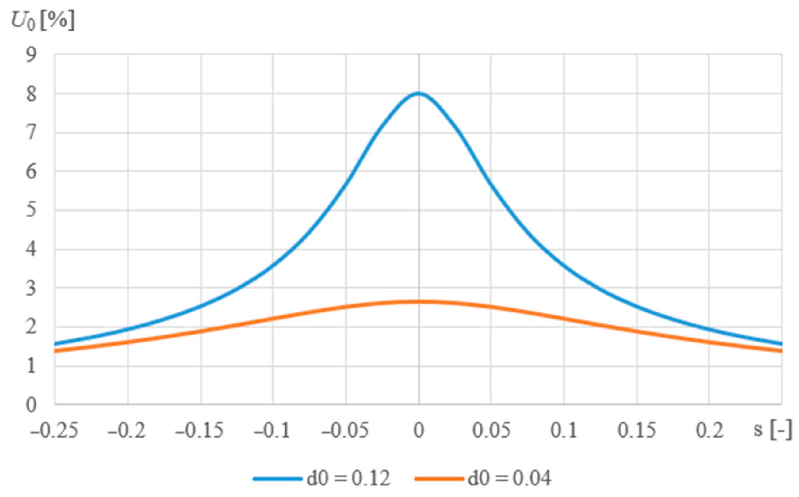
  • Resonant effect (s = 0) for d0 = 0.04 to 7.5% Uf (about 650 V);
  • Petersen coil in the neutral point of the MV network with variable reactance;
  • Resistance of the RPN resistor connected at the neutral point of the MV network from 500 to 1000 Ω.
The transient waveforms of electromagnetic phenomena under the conditions of single-phase short circuits (earth faults) were mapped as instantaneous values enabling tracking of phase variability of transient voltages in time. The simulation tests carried out focused on modelling two significant phenomena relevant to the overvoltage exposure of MV cable lines of the network:
  • Mapping the course of voltage increase in the damaged phase after the short-circuit has been cleared;
  • Determination of the maximum value of the instantaneous voltage resulting from the re-ignition of a single-phase short-circuit.
The method of conducting simulation tests enabled the initiation of disturbances with the ground in various places of the network and the observation of voltage phenomena on the busbars of the switchgear or selected points of the line.
During the tests, a series of earth fault tests were performed. Only one short-circuit event was initiated during which voltage phenomena caused by the moment of grid earthing that appeared after the disturbance was extinguished or switched off were recorded. The results of the simulation tests, presented below as relative values in relation to the basic voltage equal to the rated phase voltage of the modelled network Up = Uf, enabled both quantitative and qualitative evaluation.

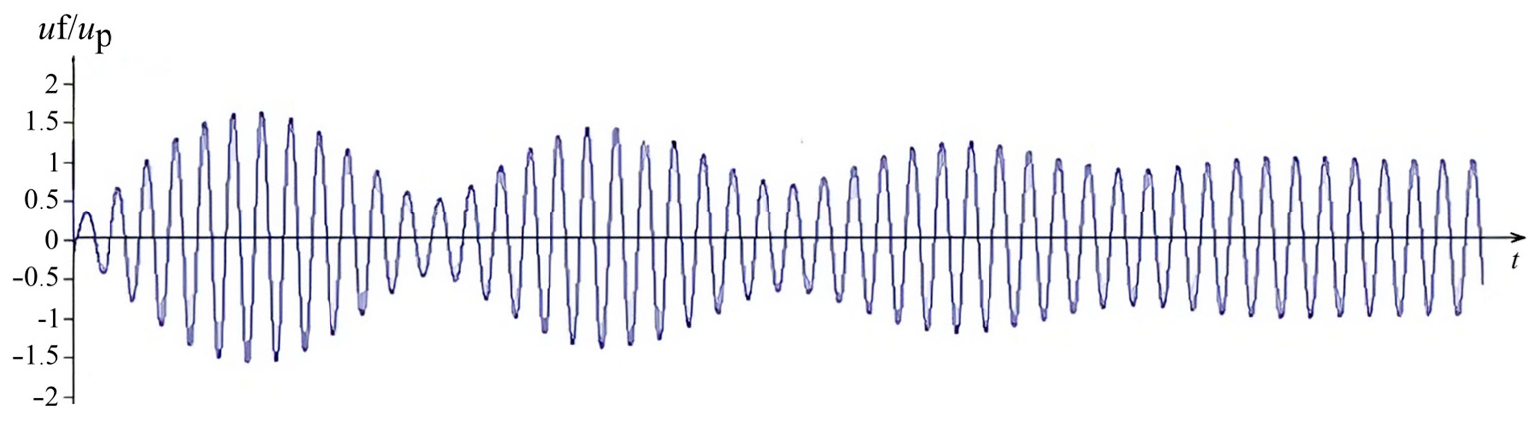
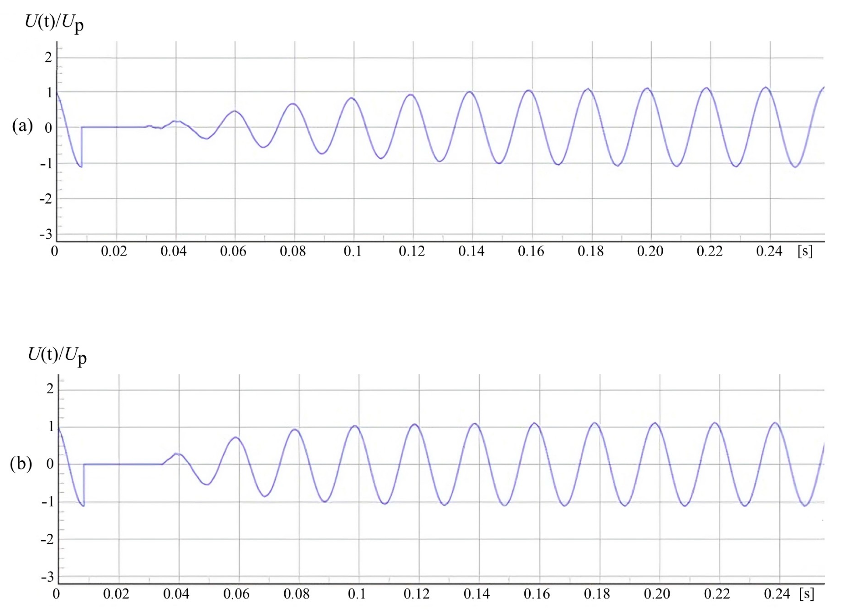
2.2. Phase Voltage Restoration after Earth Fault Disappearance

The waveform of typical voltage changes in the network after a short-term earth fault in the compensated network is shown in Figure 3, Figure 4 and Figure 5.
Comparing the waveforms presented in these figures, one can notice significant differences in the reconstruction of the earthed phase voltage after the disturbance has ceased. The speed and quality of rebuilding this voltage is of decisive importance in the process of extinguishing short-circuits in the form of an electric arc. The restoration process is the slowest in a precisely compensated network and, therefore, the effectiveness of such self-extinguishing of transient faults is absolutely the highest.
The waveform in Figure 5a shows the voltage recovery process in the phase after the earth fault has been extinguished and applies to a well-compensated network (s = 0.05) with the value of the damping coefficient at the level of d0W = 0.1. For a network with a capacitive earth current of 200 A, this corresponds to the active component in the short-circuit current of 20 A—from the natural leakage of 8 A (d0W = 0.04) and 12 A from the attached AWSCz resistor (see Figure 1).
The phenomenon of slow voltage recovery in a well-compensated network is primarily the result of a slow decay of the zero-sequence voltage in the network’s earth circuit composed of balanced Petersen coil and network capacitance elements. The formation of the voltage recovery in the phase after the earth fault is also affected by the decay frequency of the zero-sequence voltage, which, ignoring the d0 factor, is determined by the formula:
f 0 = 1 2 π L N C 0 S
which after using the transformed formula (2)
K = 1 + s = 1 ( 2 π   f S ) 2 L N C 0 S
and assuming that the mains frequency fS is 50 Hz, it takes the form:
f 0 = 50 K
The decay frequency of the zero-sequence voltage U0 is directly dependent on the detuning of the earth fault compensation and for K = 1 (i.e., exact compensation, s = 0) it is practically equal to the operating frequency of the network.
An important feature characterizing the changes in the frequency of the restoration voltage is the phenomenon that can be called the “temporary rumble effect”. For a relatively smaller detuning of the earth fault compensation (e.g., s = 0.1), the rumble effect is practically a single wave, and for a much larger detuning (s > 0.2) the beating is more visible (Figure 6).
The phenomenon of “beating” does not only concern the waveform of voltage recovery in the phase affected by the earth fault but is also visible in the voltage waveforms of the healthy phases. Figure 7 shows the voltages recorded in a real 15 kV network operating with a Petersen coil with a significant detuning factor, in which an unstable earth fault with an intermittent arc occurred. The first part of the waveforms concerns the state caused by the disturbance, and the second part is a picture of the reconstruction of the phase voltages in the network after switching off the earthed line.
The voltage changes in the network with detuned earth fault compensation presented in Figure 3, Figure 4, Figure 5 and Figure 7 are unfavorable from the point of view of the possibility of re-ignitions of the short-circuit. Therefore, in such situations, arc faults are difficult to quickly extinguish and may transform into persistent intermittent arc faults or, as a result of overvoltage phenomena, into a two-phase fault.

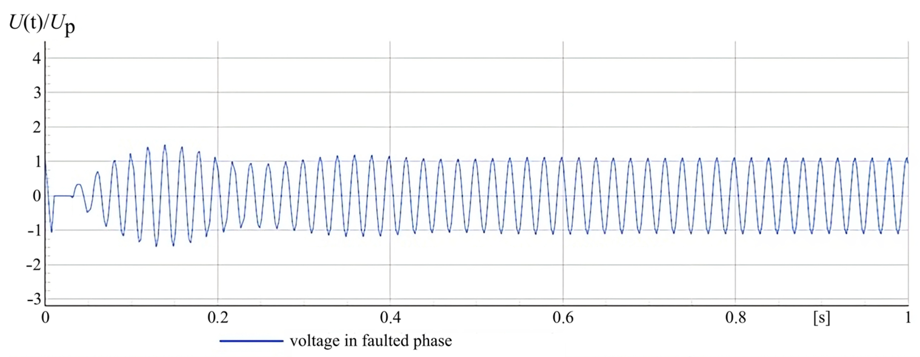
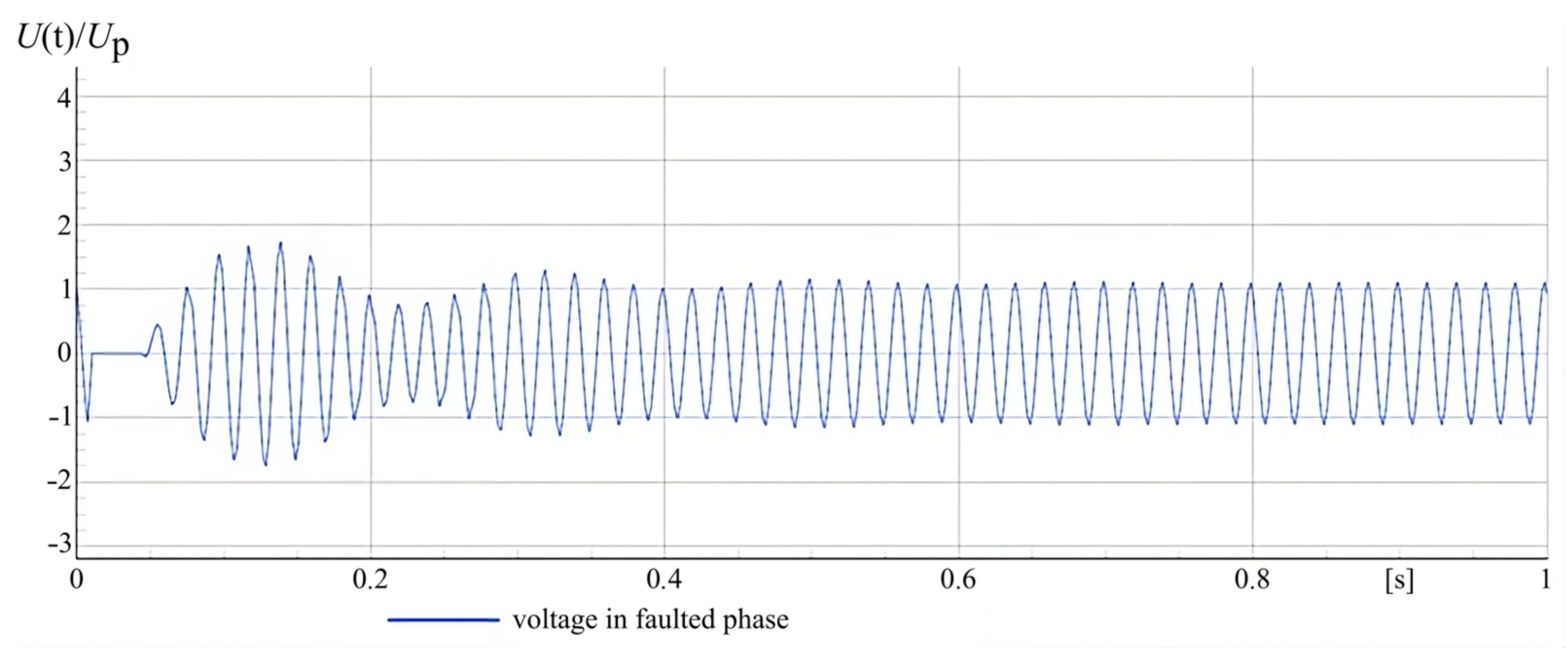
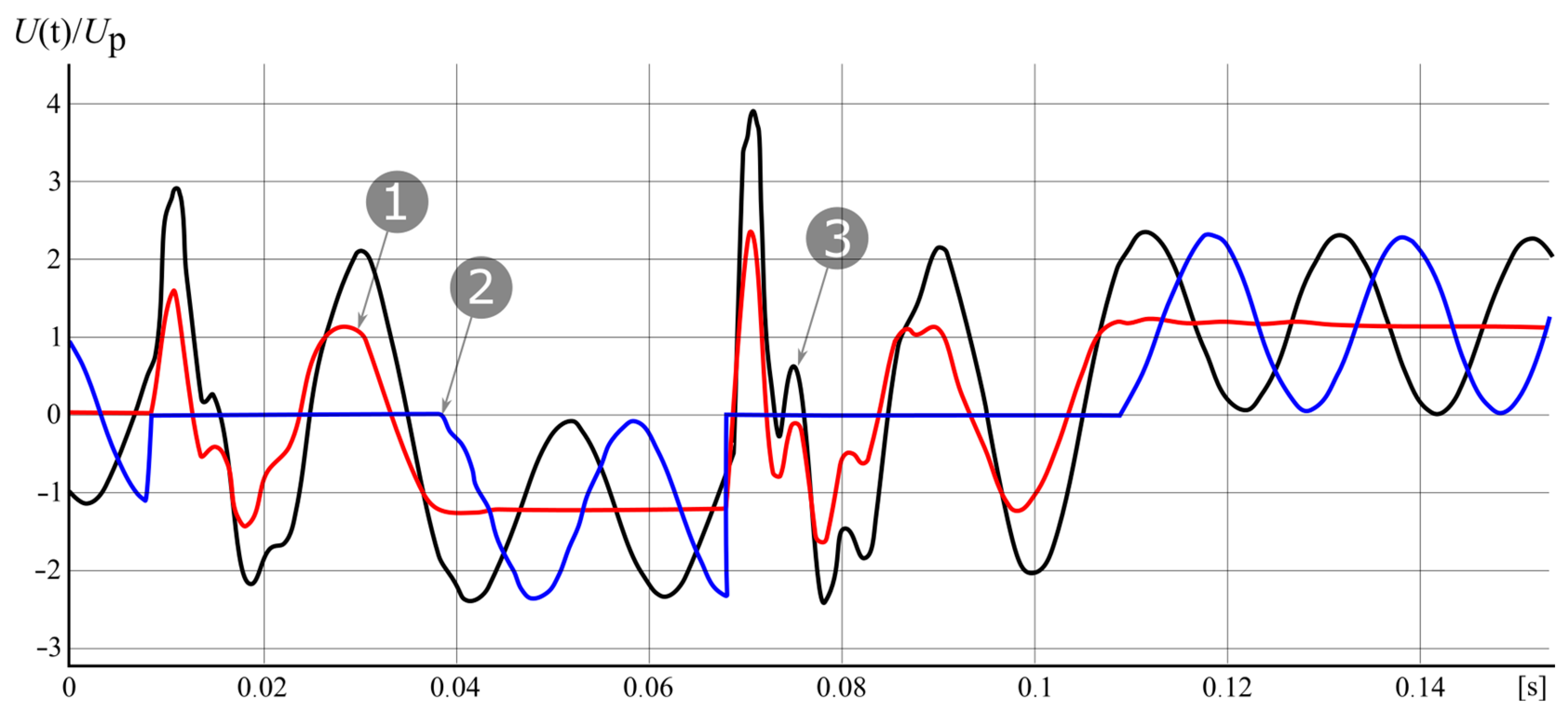
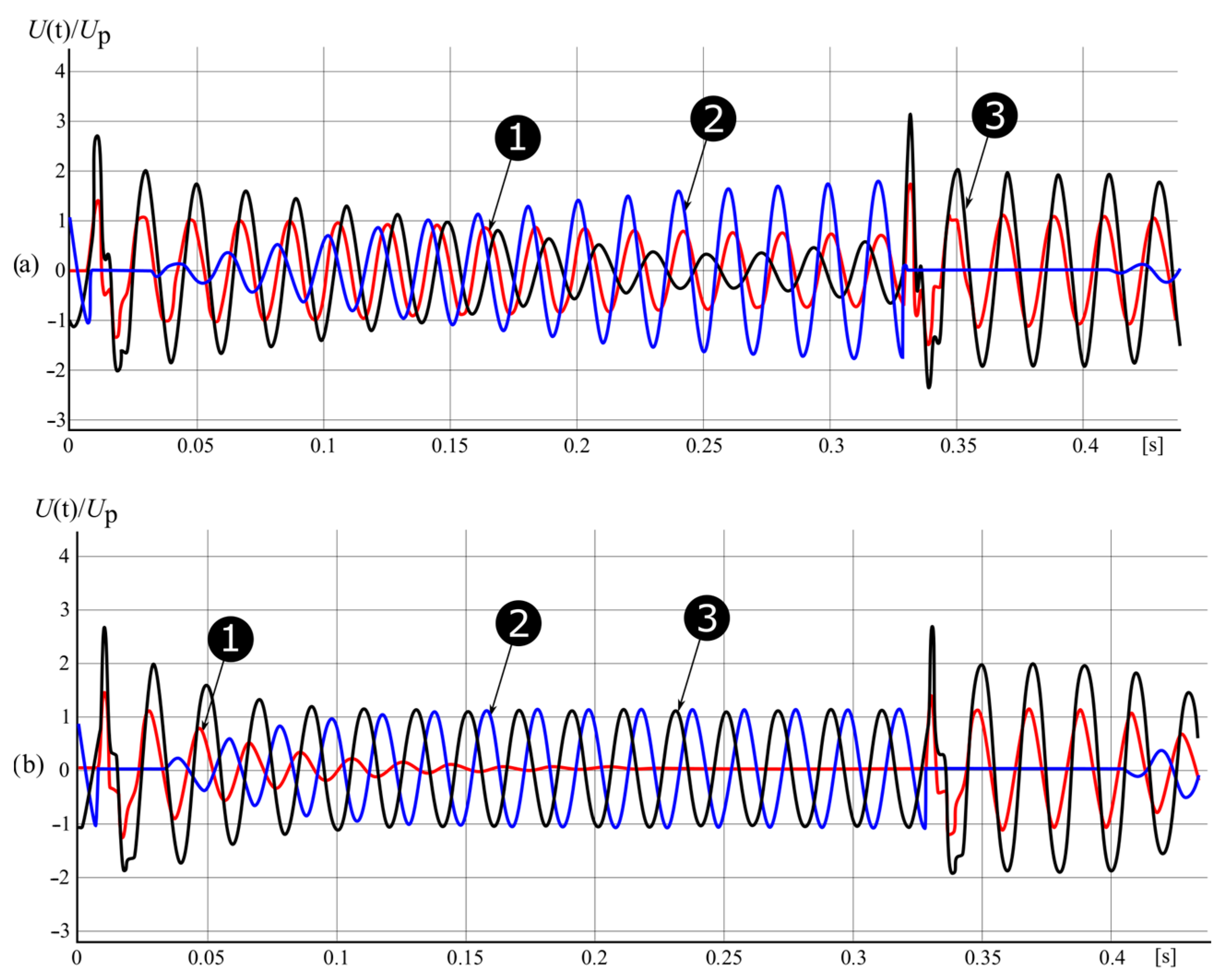
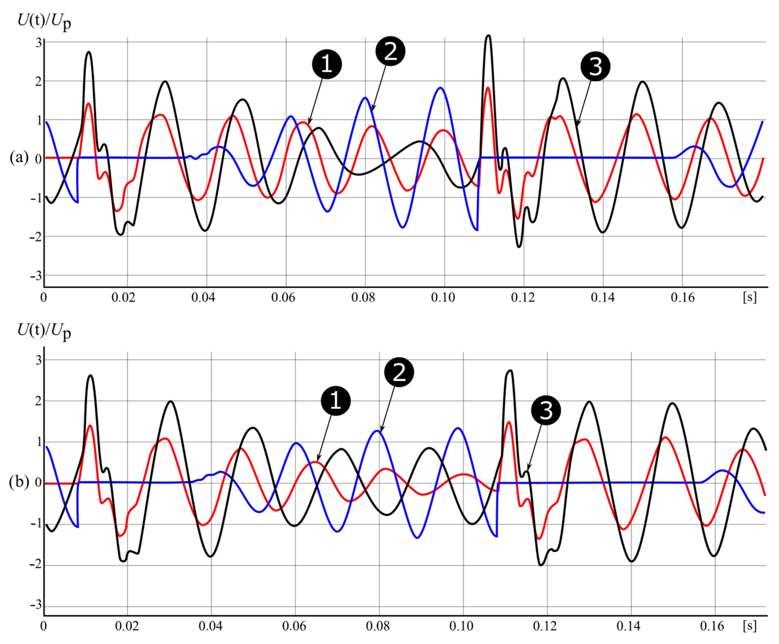
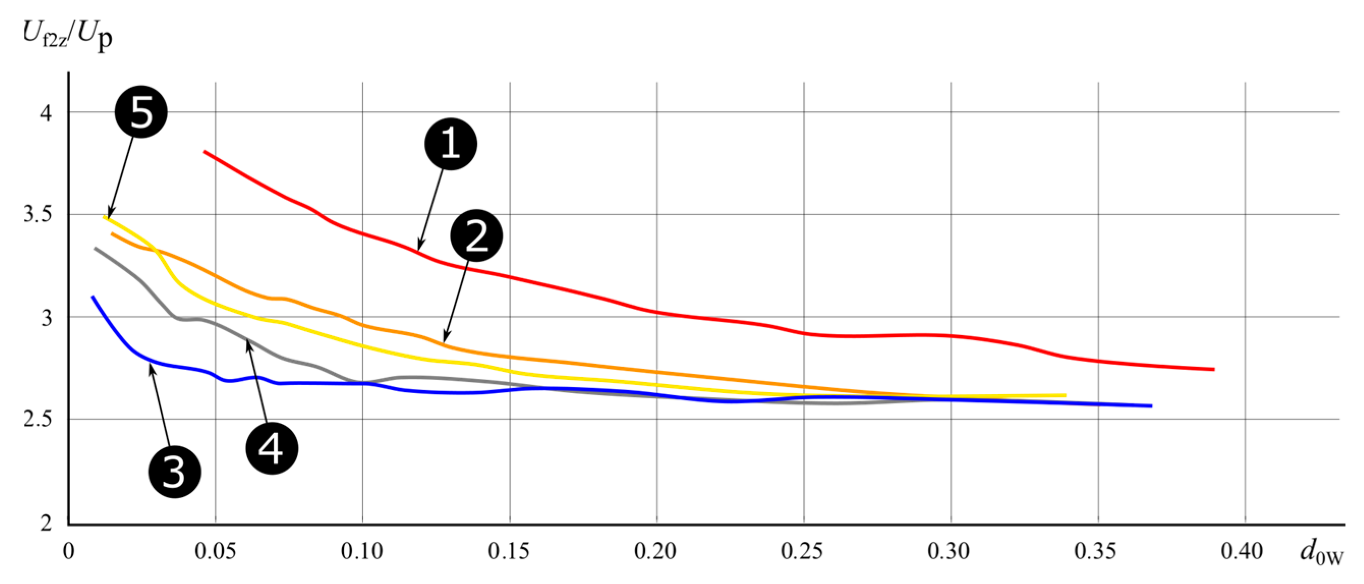
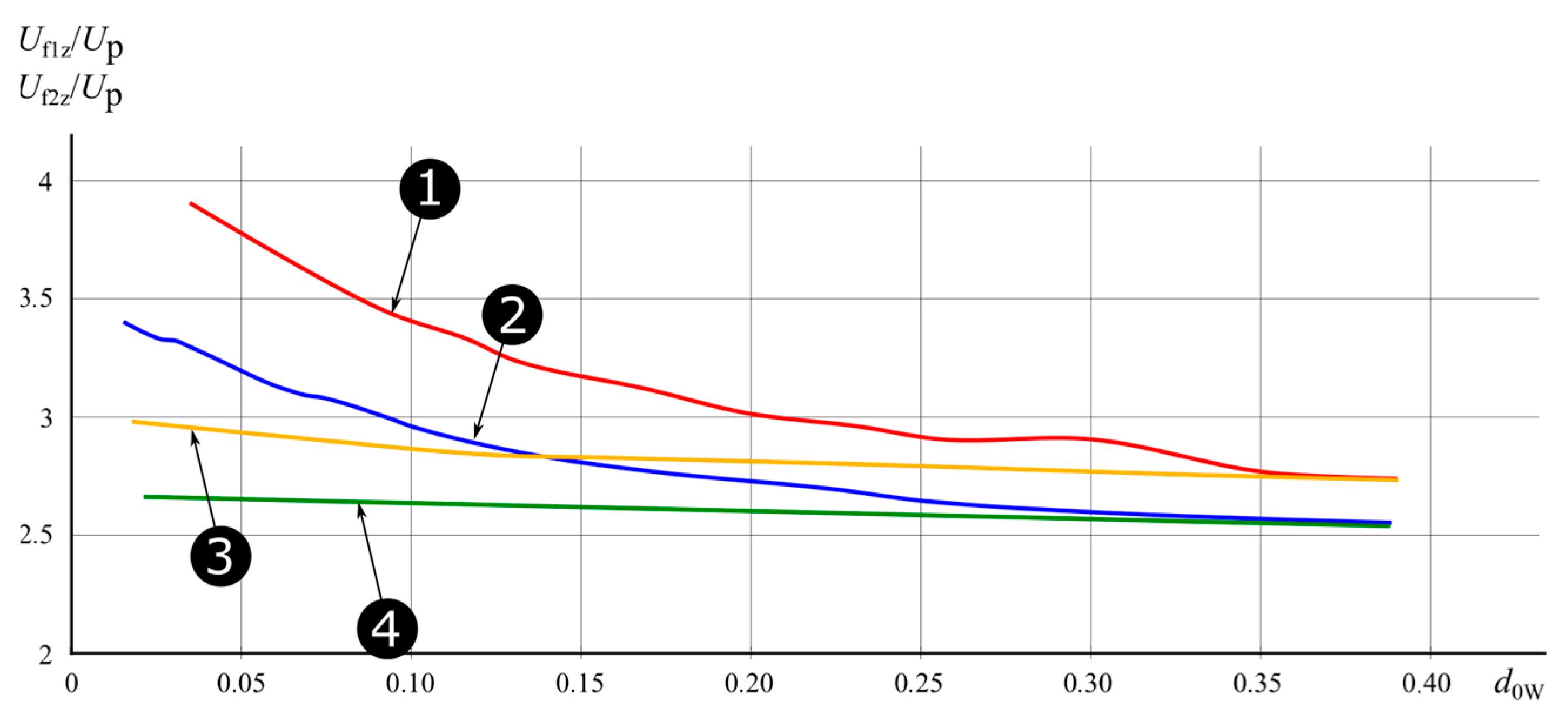
2.3. Voltage Phenomena during Multiple Earth Fault Ignitions

The purpose of further simulations was to analyze the value of maximum overvoltages in cases of re-ignition at the fault site of a previously extinguished single-phase fault, leading to the occurrence of a second single-phase fault.
Such situations are most probable in the overhead part of mixed overhead-cable networks and are the result of puncture of the air insulation and incomplete reconstruction of its insulating properties.
The research of voltage phenomena during earth faults with intermittent arcing concerned the neutral point of the network and the earthed phase and one of the healthy phases. In the simulations presented below, the voltage waveforms were mapped in the case of the first single-phase short-circuit occurring when the maximum phase voltage was reached, and the second single-phase short-circuit also at the time of the maximum phase voltage after its full recovery.
Although the research concerned a compensated network, simulation tests were also carried out for a situation in which the substation’s own needs are turned off and the network goes into a state with an isolated neutral point. As shown in Figure 8, the first ignition of an earth fault generates overvoltages occurring in the healthy phase at a level three times the rated phase voltage. In contrast, the overvoltage level after the second ignition reaches values greater than four times the phase voltage.
The level of these overvoltages was estimated assuming that the damping factor of the earth fault circuit resulted from the natural properties of the network and did not exceed the value d0 = 0.04. The possibilities of limiting such overvoltages are well known and in practice consist in earthing the neutral point through a resistor [17,23,24].
The following Figure 9 and Figure 10 show examples of voltage waveforms caused by a double-ignition arc fault in an accurately compensated network and with pronounced reactor distortion. For an exactly compensated network, the occurrence of further ignitions is less likely and could occur with a long delay (e.g., after 0.3 s) resulting from the slow voltage recovery of the faulty phase after the disappearance of the first fault event. A time of 0.3 s is generally sufficient for full rebuilding of the post-fault space insulation.
Therefore, in well-compensated networks, the probability of a second arc-fault ignition is only possible during particularly persistent disturbances and successive ignitions occurring at clear intervals should be treated as a new disturbance with a single ignition.
The situation is different in networks with pronounced earth fault compensation distortion and the probability of multiple ignitions occurring in the short-circuit process is much higher.
Comparing the waveforms shown in Figure 10a,b, one can notice a significant effect of damping on the level of overvoltages caused by the second ignition. However, in well-compensated networks, the probability of the occurrence of a second arc fault ignition is relatively low, and in the event of persistent disturbances, subsequent ignitions occur at clear intervals, which should be treated as another disturbance with a single ignition. The situation is different in networks with a clear detuning of ground fault compensation and the probability of multiple ignitions in the short-circuit process is much higher.
The detailed tests carried out in the form of numerous earth fault tests in the modeled MV network allowed us to estimate the level of overvoltage hazards appearing after the re-ignition of the electric arc of the ongoing disturbance. The level of these overvoltages is shown in Figure 11 and Figure 12 in the form of appropriate curves that describe the relationship of the overvoltage index for various compensation states depending on the value of the d0W damping coefficient. The overvoltage indicator was marked as:
U f 1 Z U p
for the first short-circuit ignition,
U f 1 Z U p
for the second short circuit ignition. where: Uf1Z and Uf2Z—maximum values of temporary overvoltages in the phases of healthy networks for the first or second ignition, Up—the amplitude of the network operating phase voltage.
In both Figure 11 and Figure 12, part of the curves shown are for interference in networks with extremely low damping values (even d0 < 0.02). Tests in real networks show that the damping factor most often assumes the values: d0 = 0.02 for a network with an isolated neutral point and d0 = 0.04 for a network with a neutral point earthed by a Petersen coil.

3. Discussion of Results

A compensated MV network with cable and overhead structure, powered by a 15 kV switchgear, was adopted as the basic object of the research, whose measured values of earth fault parameters were used to map individual elements of computer tests in the field of voltage phenomena. These tests have confirmed that in compensated networks there are overvoltage hazards caused by an earth fault characterized by an electric arc, in which multiple ignitions occur. The overvoltage effects of such disturbances are especially visible during the operation of the reactors with a clear detuning of the ground fault compensation. The limitation of overvoltages in this case is possible by increasing the attenuation of the earth fault circuit and the conducted tests have shown that visible benefits can be obtained by applying the following measures:
  • In cases of compensation detuning at the level of 0.1 < s < 0.2, the damping coefficient d0W should be increased to a value in the range of 0.1 ÷ 0.2;
  • With detunings greater than 0.2 < s < 0.3, the value of the damping coefficient d0W should be increased to a value above 0.2.
Obtaining such a level of damping in the earth fault circuit makes it possible to limit overvoltages caused by multiple ignitions to the level of overvoltages caused by short-circuits extinguished after a single ignition.
When choosing the resistance at the neutral point, the formula can be used to obtain the recommended value of the damping factor.
R 1 ω C 0 S ( d 0 W d 0 )
where:
  • d0—natural damping coefficient of earth fault circuits;
  • d0W—resultant damping factor recommended to limit the effects of earth fault re-ignitions;
  • C0S—earth capacitance of the network.
In the work, the tests were carried out for the MV network, in which a relatively high value of the earth capacitive current was measured at the level of 200 A and its natural damping factor was determined at the level of 0.04.
Assuming that the recommended coefficient d0W = 0.14, the desired value of the resistance of the RPN should not exceed the value of 450 Ω, and for networks with a capacitive earth current of 100 A, the value of RPN < 900 Ω. Assuming that the allowed value of the earth fault current due to the possibility of spontaneous extinction is IKdop, it is possible to determine the maximum detuning factor at which the network will retain the ability to properly suppress overvoltages during arc earth faults. Then use the formula
s ( I k d o p I C S ) 2 d 0 W 2
where: IKdop—permissible value of short-circuit current due to the requirements of protection against electric shocks;
  • ICS—value of network capacitive earth current.
Assuming that IKdop = 30 A, ICS = 200 A and d0W = 0.13, the detuning factor of the earth fault compensation should not exceed 0.0748 (s < 0.075).
Capacitive earth currents in compensated MV networks with a cable-overhead structure, typical for Poland, rarely exceed 200 A, and therefore in many cases it is possible to obtain the recommended attenuation of earth fault circuits using devices installed in MV switchgears that implement ACFA/AWSCz systems.
It should be noted that these devices are permanent equipment of Polish MV networks operating with the neutral point earthed by Petersen coil. Minor changes in the program of their operation will also make it active in the state of normal operation of the network causing constant required damping of the earth fault circuit. These changes will not cause negative effects in the efficiency of earth-fault protections, on the contrary, they can significantly improve it. This applies in particular to conductance protections, for which the additional resistance at the neutral point of the network reduces the effect of natural earth asymmetry on the setting conditions of the voltage start-up segment, improving their effectiveness during high-resistance short circuits.

4. Conclusions

Analysis of the research results presented allows the following conclusions to be drawn:
  • During earth faults accompanied by an intermittent electric arc (re-ignitions), the overvoltage factor may exceed the value of 3. For networks with an insulated neutral point, the factor values are the highest and can reach levels close to 4.
  • In compensated MV networks, the effects of overvoltage caused by intermittent arc earth faults depend on the degree of matching of the shunt reactor to the capacitance and on the level of attenuation of the earth fault circuit. The possibility of re-ignition of the electric arc is determined by the process of rebuilding the voltage of the phase affected by the disturbance.
  • The slow decay of the zero-sequence voltage in a fully compensated network favors the slow reconstruction of the damaged phase voltage, limiting the possibility of re-ignition shortly after the short-circuit is extinguished.
  • The detuning of the earth fault compensation has a negative effect on the process of voltage recovery after the earth fault disappearance, causing beating effects, which, already with the detuning at a level above 0.1 (s > 0.1), can reduce the resistance of the arc space to re-ignition, causing overvoltages often exceeding three times operating voltage of the network.
  • The unfavorable level of overvoltages caused by an intermittent arc (multiple ignitions) in networks operating with ground fault compensation detuning can be reduced by increasing the earth fault circuit attenuation by installing additional resistance in the neutral point or using ACFA/AWSCz devices for this purpose.
  • The proposed technical solution should be particularly recommended in HV/MV substations, in which follow-up earth fault compensation units operate, which are subject to the tuning process to the set value and carried out automatically after each change in the configuration of the MV network.
  • It should also be noted that increasing the conductance at the neutral point of a network with earth asymmetry will cause certain negative effects. These are due to energy losses in the circuit of the additional resistance installed. The proposed values of this resistance for a 15 kV network are around 500 ohms and therefore the value of the lost active power is relatively very small. In typical MV networks with a natural asymmetry of about 0.5 %, this power, even assuming ideal earth fault compensation, does not exceed 100 W.

Author Contributions

Conceptualization, J.L.; methodology, J.L.; software, J.A. and A.W.; validation, J.A. and B.O.; formal analysis, J.A.; investigation, A.W. and B.O.; data curation, B.O., A.W., and B.S.; writing—original draft preparation, J.L., B.O. and J.A.; writing—review and editing, B.O. All authors have read and agreed to the published version of the manuscript.

Funding

This research and APC was financed from resources of the Polish Ministry of Science and Higher Education for Statutory Activities No. 0711/SBAD/4617.

Data Availability Statement

The data presented in this study are available on request from the corresponding author. The data are not publicly available due to privacy reasons.

Conflicts of Interest

The authors declare no conflicts of interest. The funders had no role in the design of the study; in the collection, analyses, or interpretation of data; in the writing of the manuscript; or in the decision to publish the results.

Nomenclature

ACFAActive Current Forcing Automation
C0Searth capacitance of the network
d0natural damping coefficient of earth fault circuits
d0Wresultant damping factor recommended to limit the effects of earth fault re-ignitions
GAWSCzconductance of AWSCz/ACFA devices after switching on the RAWSCz resistor
G0network transverse conductance
IKdoppermissible value of short-circuit current due to the requirements of protection against electric shocks
LNPetersen coil inductance
LPNinductance of the reactor at the neutral point of the network
Kearth fault compensation coefficient
Rarcelectric arc resistance
RAWSCzresistance of AWSCz/ACFA resistor
RFtransition resistance
RPNresistance of the resistor at the neutral point of the network
scompensation detuning factor
Ufphase voltage
Uf1Zmaximum values of temporary overvoltage in the phases of healthy networks for the first ignition
Uf2Zmaximum values of temporary overvoltage in the phases of healthy networks for the second ignition
U0zero-sequence voltage
Upamplitude of the network operating phase voltage
ωnetwork working pulsation (ω = 2πf)

References

  1. Druml, G.; Kugi, A.; Parr, B. Control of Petersen Coils. In Proceedings of the XI International Symposium on Theoretical Electrical Engineering, Linz, Austria, 19–22 August 2001; pp. 1–7. [Google Scholar]
  2. Waters, M.; Willheim, R. Neutral Grounding in High-Voltage Transmission; Elsevier: Amsterdam, The Netherlands, 1956. [Google Scholar]
  3. CEER. CEER Benchmarking Report 6.1 on the Continuity of Electricity and Gas Supply; CEER: Brussels, Belgium, 2018. [Google Scholar]
  4. Mohar, T.; Valenčič, L.; Batič, D. Reliability Impact Factor Analysis for Distribution in Slovenia. In Proceedings of the 22nd International Conference on Electricity Distribution, Stockholm, Sweden, 10–13 June 2013; CIRED: Stockholm, Sweden, 2013. [Google Scholar]
  5. Siirto, O.; Loukkalahti, M.; Hyvarinen, M.; Heine, P.; Lehtonen, M. Neutral Point Treatment and Earth Fault Suppression. In Proceedings of the 2012: 8th International Conference-2012 Electric Power Quality and Supply Reliability, Conference Proceedings, Tartu, Estonia, 11–13 June 2012; pp. 193–198. [Google Scholar] [CrossRef]
  6. Anderson, E. Przepięcia Wewnętrzne w Sieciach Średnich Napięć i Ich Ograniczanie. (Internal Overvoltages in Medium Voltage Networks and Their Limitation); Polska Akademia Nauk-Komitet Elektrotechniki: Warsaw, Poland, 1997; Volume 26. [Google Scholar]
  7. Jakubowski, J. Podstawy Teorii Przepięć w Układach Elektroenergetycznych (Fundamentals of Overvoltage Theory in Power Systems); PWN: Warsaw, Poland, 1968. [Google Scholar]
  8. Oramus, P.; Furgał, J. Analiza Przepięć Ziemnozwarciowych w Sieciach Rozdzielczych (Ground Fault Analysis in Distribution Networks). Przegląd Elektrotechniczny (Electrotech. Rev.) 2015, 91, 149–152. [Google Scholar]
  9. Peters, J.F.; Slepian, J. Voltages Induced by Arcing Grounds. J. Am. Inst. Electr. Eng. 1923, 42, 781–792. [Google Scholar] [CrossRef]
  10. Shirkovets, A.I. Modeling of Transient Processes at Ground Faults in the Electrical Network with a High Content of Harmonics. In Proceedings of the 2013 2nd International Conference on Electric Power Equipment-Switching Technology, ICEPE-ST 2013, Matsue, Japan, 20–23 October 2013. [Google Scholar] [CrossRef]
  11. Varetsky, Y. Overvoltages in MV Industrial Grid under Ground Faults. Energy Eng. Control. Syst. 2019, 5, 75–80. [Google Scholar] [CrossRef]
  12. Varetsky, Y.; Bakhor, Z.; Ravlyk, A. Transients in 10–35 KV Electric Networks with Ungrounded Neutrals under Earth Faults. In Proceedings of the VII International Symposium “Short Circuit Currents in Power Systems”, Warsaw, Poland, 10–12 September 1996. [Google Scholar]
  13. Bakhor, Z.; Yatseiko, A.; Ferensovych, R. Multiplicity of Overvoltages during Arc Single Phase Earth Faults in 35 KV Electrical Grids. Energy Eng. Control Syst. 2021, 7, 111–116. [Google Scholar] [CrossRef]
  14. Yatseiko, A.Y.; Kozak, K.V.; Horoshko, O.B. Investigation of the Influence of a Neutral Mode in the 35 KV Electrical Grid at the Values of Arc Overvoltages (in Ukrainian). Sci. Pap. Donetsk Natl. Tech. Univ. Ser. “Electr. Eng. Power Eng.” 2013, 2, 314–318. [Google Scholar]
  15. Bergeal, J.; Berthet, L.; Grob, O.; Bertrand, P.; Lacroix, B. Single-Phase Faults on Compensated Neutral Medium Voltage Networks. In Proceedings of the 12th International Conference on Electricity Distribution, Birmingham, UK, 17–21 May 1993; CIRED: Birmingham, UK, 1993. [Google Scholar]
  16. Dolník, B.; Kurimský, J. Contribution to Earth Fault Current Compensation in Middle Voltage Distribution Networks. Przegląd Elektrotechniczny (Electr. Rev.) 2011, 87, 220–224. [Google Scholar]
  17. Lorenc, J.; Rakowska, A. Limitation of Interruptions in Service of MV Distribution Systems by Improvement of Lines Insulation and Fast Localising of Earth Fault. IEE Conf. Publ. 2005, 3, 309–312. [Google Scholar] [CrossRef]
  18. Heidary, A.; Radmanesh, H.; Bakhshi, A.; Samandarpour, S.; Rouzbehi, K.; Shariati, N. Compound ferroresonance overvoltage and fault current limiter for power system protection. IET Energy Syst. Integr. 2020, 2, 325–330. [Google Scholar] [CrossRef]
  19. Rybakov, L.M.; Lastochkin, S.V.; Kanjugin, O.I. Types of overvoltages in 10–35 kV distribution networks and modern methods and means of their limitation. J. Phys. Conf. Ser. 2020, 1499, 012026. [Google Scholar] [CrossRef]
  20. Ferreira, R.S.; Favoreto, H.H. Transient overvoltages due to intermittent-ground faults in an industrial power system grounded by a resistance connected to the secondary of a grounding transformer. Electr. Power Syst. Res. 2023, 220, 109327. [Google Scholar] [CrossRef]
  21. DigSILENT. DigSILENT Power Factory User Manual; DigSILENT: Gomaringen, Germany, 2017. [Google Scholar]
  22. Lorenc, J. Admitancyjne Zabezpieczenia Ziemnozwarciowe (Admitance Earth Fault Protection); Wydawnictwo Politechniki Poznańskiej: Poznań, Poland, 2007; ISBN 978-83-7143-342-9. [Google Scholar]
  23. Michalik, M.; Rebizant, W.; Hoppel, W.; Lorenc, J. Optimization of MV Network Neutral Point Earthing Mode with Respect to Transient Ground-Fault Overvoltages. In Proceedings of the 8th Int. Symposium on Short Circuit Currents in Power Systems SCC98, Brussels, Belgium, 8–20 October 1998; pp. 287–292. [Google Scholar]
  24. Vershoore, J. Choix Du Regime de Neutre d’un Reseau Industriel Haute Tension 1 ă 36 KV. RGE 1980, 11, 727–736. [Google Scholar]
Figure 1. AWSCz forcing system with forcing resistor connected to the additional one low-voltage winding of the compensating coil LPN.
Energies 17 00093 g001
Figure 2. Curves of the zero-sequence voltage of the network U0 in a compensated network with earth asymmetry at the level of 0.45%, depending on the degree of compensation detuning and the value of the damping coefficient d0.
Energies 17 00093 g002
Figure 3. Waveform of the phase voltage of the faulted MV network after the disappearance of the earth fault in the overcompensated network (s = 0.2) with natural damping coefficient d0 = 0.04.
Energies 17 00093 g003
Figure 4. Waveform of the phase voltage of the faulted MV network after the disappearance of the earth fault in the uncompensated network (s = −0.2) with natural damping coefficient d0 = 0.04.
Energies 17 00093 g004
Figure 5. Voltage waveform of the faulted phase after the short-circuit disappearance in the compensated network (s = 0.05) and damping coefficients d0W = 0.1 (graph (a)) and d0W = 0.25 (graph (b)).
Energies 17 00093 g005
Figure 6. The process of restoring the voltage of the earthed phase after the disturbance disappearance, recorded in a network with high compensation detuning (s = 0.3, d0 = 0.04).
Energies 17 00093 g006
Figure 7. Voltage waveforms in a real 15 kV network recorded during an intermittent arc earth fault in the L1 phase [22].
Energies 17 00093 g007
Figure 8. Waveforms of voltages in the event of a re-occurrence of a short-circuit after its short-circuit extinction in the MV network with an insulated neutral point. (1—neutral point voltage, 2—earth phase voltage, 3—healthy phase voltage).
Energies 17 00093 g008
Figure 9. Waveforms of voltages in the event of a re-occurrence of a short-circuit after its short-circuit extinction in the compensated MV network (s = 0) for two cases: for d0 = 0.04 (graph a) and for d0W = 0.14 (graph b) (1—neutral point voltage, 2—earth phase voltage, 3—healthy phase voltage).
Energies 17 00093 g009
Figure 10. Waveforms of voltages in the event of a re-occurrence of a short-circuit after its short-circuit extinction in a compensated MV network with significant detuning (s = 0.2) for two cases: for d0 = 0.04 (graph a) and for d0W = 0.14 (graph b) (1—neutral point voltage, 2—earth phase voltage, 3—healthy phase voltage).
Energies 17 00093 g010
Figure 11. Values of overvoltages in the MV network at the occurrence of a single-phase short-circuit as a result of repeated ignition of Uf2z/Up in a fragment of the overhead network for various parameters of compensation and as a function of the damping factor d0W. 1—network with isolated neutral point (s = −1), 2—compensated network with significant detuning (s = 0.3), 3—finely compensated network (s = 0), 4—compensated network (s = 0.1), 5—compensated network (s = 0.2).
Energies 17 00093 g011
Figure 12. Values of overvoltages in the MV network at the initial single-phase short-circuit (Uf1z) and overvoltages Uf2z resulting from repeated single-phase short-circuit as a result of re-ignition in a fragment of the overhead network for various parameters of compensation and as a function of the damping factor d0W. 1—Uf2z/Up in a network with an isolated neutral point (s = −1), 2—Uf1z/Up in a network with an isolated neutral point (s = −1), 3—Uf2z/Up in a compensated network with significant detuning (s = 0.3), 4—Uf1z/Up in the compensated network (s = 0.1).
Energies 17 00093 g012
Disclaimer/Publisher’s Note: The statements, opinions and data contained in all publications are solely those of the individual author(s) and contributor(s) and not of MDPI and/or the editor(s). MDPI and/or the editor(s) disclaim responsibility for any injury to people or property resulting from any ideas, methods, instructions or products referred to in the content.

