Article

Heat Extraction Evaluation of CO2 and Water Flow through Different Fracture Networks for Enhanced Geothermal Systems

1
School of Petroleum Engineering, China University of Petroleum (East China), Qingdao 266580, China
2
Northwest Oil Field Branch of Sinopec, Urumqi 830011, China
3
Tarim Oilfield Company, Alar 842209, China
*
Author to whom correspondence should be addressed.
Energies 2024, 17(1), 86; https://doi.org/10.3390/en17010086
Submission received: 28 October 2023 / Revised: 18 December 2023 / Accepted: 19 December 2023 / Published: 22 December 2023
(This article belongs to the Section H2: Geothermal)

Abstract

:
Enhanced geothermal system (EGS) technologies have been developed to improve geothermal energy production from hot dry rock (HDR). In this study, discrete fracture network models for geometric topological networks that consider different parameters (the fracture density and the fracture length index) were built on the basis of fractal geometry theory. The heat extraction processes of CO2 and water as the working fluid through different discrete fracture networks were simulated with the application of the thermal–hydraulic–mechanical (THM) coupled method. A series of sensitivity analyses were carried out to reveal the influences of fracture parameters on heat transfer processes. Based on the simulation results, heat extraction efficiencies and temperature distributions in the reservoir of CO2 and water as the working fluid were compared, which showed that CO2 as the working fluid can bring a faster thermal breakthrough. It was found that the fracture length index a = 2.5 and the fracture density I = 5.0 can provide the highest heat extraction rate compared with other cases. This study provides a detailed analysis of fracture parameters and working fluids, which will contribute to the optimized management of geothermal energy production.

1. Introduction

Hot dry rock (HDR), a type of geothermal resource, is a clean and renewable type of energy that can contribute to reducing CO2 emissions into the atmosphere and help to mitigate global warming [1,2,3]. With the aim of enabling efficient geothermal energy production from HDR, enhanced geothermal systems have been developed and applied to several projects across the world [3,4,5,6]. The key function of an EGS is to generate a connected fracture network in the reservoir and consequently improve permeability to allow working fluids to flow through the reservoir. Therefore, it is vital to characterize fracture networks and working fluid flow through fracture networks in the reservoir.
In recent years, many investigations have studied heat and mass transfer processes based on different fracture models in reservoirs used for geothermal energy production [7,8,9,10]. A discrete fracture model that integrates the hydraulic–thermal coupled process was previously built to evaluate the efficiency of heat extraction from a geothermal reservoir [11]. Fox et al. [12] proposed an analytical model to simulate heat transfer via the two-dimensional discrete fracture network in geothermal reservoirs. Sun et al. [13] developed a model combining the discrete fracture network with the hydraulic–thermal–mechanical coupled process to investigate geothermal energy production from hot dry rock. The salt precipitation process in a fractured geothermal reservoir model used for geothermal energy production was previously simulated, reflecting the fact that salt precipitation occurring in fractures has negative effects on geothermal energy production [14]. To optimize geothermal energy production from fractured geothermal reservoirs, an optimization method was previously developed and validated in [15]. Li et al. [16] developed a rough-walled discrete fracture network model to analyze the effects of rough-walled fractures on heat extraction and compared them to the parallel-plate discrete fracture network model. Moreover, the flow distributions corresponding to heat extraction efficiencies in a discrete fracture model during the EGS process have tight relationships with the total amount of fractures, as shown in [17].
Initially, water was adopted by researchers as the working fluid for heat extraction from geothermal reservoirs due to its low cost, easy availability, and stable properties [4,8,18]. Using water as the working fluid, a numerical model was built to optimize production rates from geothermal reservoirs in [15]. A porous media model for water flow in the EGS was developed for heat transfer characterization and shows that a triple-well set has better performance [19]. Experiments were performed to measure water properties under geothermal reservoir conditions to accurately calibrate Tai-type parameters [20]. Compared to water, the advantages of CO2 include lower viscosity, higher compressibility, no mineral interactions, and CO2 sequestration in the reservoir [21,22,23]. A dual-porosity model was applied to investigate the effects of salt precipitation on geothermal energy production rates with the injection of CO2 as the working fluid, as shown in [11]. The distribution of fractures caused by the injection of CO2 into the reservoir can be accurately characterized through the combination of geophysical data [11]. Jiang et al. [24] investigated the convective heat transfer of CO2 through a single parallel-plate fracture and proposed a correlation to improve the performance of geothermal energy production. Zhang et al. [25] developed a single rough fracture model to characterize CO2 heat and mass transfer for the EGS.
Currently, research into geothermal production is in the early stage of development, and scholars have proposed a variety of methods for the development of geothermal resources, of which experimental and numerical research are the two main methods used. For the current development of large geothermal fields, many numerical simulation methods have been widely used in the field of geothermal production and development research, such as the dry-heat rock reservoir thermal storage system heat extraction method [26], the multi-scale hydrothermal geothermal sustainable heat extraction method [27], the numerical simulation of heat transfer through artificial cracks [28], supercritical system heat extraction analysis [29], etc. Based on numerical simulation, geothermal energy production has good pre-conditions and a strong theoretical basis.
In order to accurately simulate the EGS process, the fracture properties, including the fracture aperture, inclination density, etc., must be accurately reflected in the model. In addition, the pressure- and temperature-dependent properties of working fluids should be considered. In this paper, fracture properties are described, a discrete fracture model integrating the fracture connectivity and coupled hydraulic–thermal–mechanical processes is constructed via the COMSOL finite element numerical simulator, and numerical simulations of geothermal development are carried out to realistically reflect the EGS process.

2. Model Descriptions

2.1. Hydraulic–Thermal–Mechanical Coupled Modeling

In this study, a two-dimensional reservoir conceptualization model of a two-pore structure consisting of a discrete fracture network and a rock matrix is established. The left boundary was set as the injection well, and the right boundary corresponded to the production well, as shown in Figure 1. The conceptualization model is used to simulate the heat extraction characteristics of different workings. Correspondingly, four assumptions are made for the mathematical model developed in this study:
  • The rock matrix is isotropic, and the permeability of the rock matrix is very small compared to that of the fractures, which means that the rock matrix is assumed to be impermeable;
  • The working fluid (water/CO2) remains in a liquid or supercritical state under reservoir conditions;
  • Darcy’s law is applicable to fluids flowing in the reservoir;
  • The fluids that originally existed in the reservoir are the same as those in the working fluid.
The mass and heat transfer in the fractures and rock matrix for the model are individually demonstrated in the following section [30]. Relevant governing equations in the fracture are expressed in the following forms [31]:
d f S f p t + τ u f = d f e f t + Q f
d f ρ i C i T i t + d f ρ i C i u f τ T i = τ d f λ i τ T i + h T m T f
u f = d f k f μ i τ p + ρ i g τ z
where f represents the fracture, d f represents the fracture thickness, Q f represents the mass transfer between the fracture and rock matrix, h represents the convection heat transfer coefficient, τ represents the derivation in the tangential direction of the fracture, S represents the storage coefficient, u f represents the flow rate, e f represents the volumetric strain, T i represents the temperature, C i represents the specific heat conductivity, λ i represents the heat conductivity, k f represents the permeability, u f represents the fluid viscosity, g represents the gravity acceleration, p represents the pressure, t represents the time, z represents a unit vector, ϕ represents the rock matrix porosity, and i represents the miscible flow with different proportions.
The mass and energy conversion equations and Darcy’s velocity described by Darcy’s law in the rock matrix are written as described in [28,31,32]:
S m p t + u m = e m t
ϕ ρ i C i T i t + ρ i C i u m T i = ϕ λ i 2 T i
u m = k m μ i p + ρ i g z
where m is the rock matrix.
Moreover, the other parameters for equations used to describe mass and heat transfer in fractures are the same as the parameters in the rock matrix.
Since the permeability of the rock matrix was extremely small, the influences of stress on the permeability of the rock matrix could be ignored. The permeability of the fracture could be expressed by taking the normal effective stress into consideration [32]:
K f = K 0 e ( α σ n )
where α is the influence coefficient, which depends on the fracture state in rock mass. When K 0 is σ′n = 0, the fracture permeability can be calculated based on the cubic law K 0 = d f 2 / 12 .
The local permeability was assumed to be constant for all matrix elements. The effective permeability of the fractured rock is obtained by inverting Darcy’s law as follows:
K e f f = Q μ p i n p o u t L
where Q is the volumetric flow rate through the inlet face of the fractured rock, L is the length of the model domain, and p i n and p o u t are the hydraulic head at the inlet and outlet, respectively.

2.2. Heat Transfer Simulation and Evaluation

Two parameters were adopted for better analysis in this study. The average outlet temperature and thermal recovery factor were adopted to evaluate the performance of heat production from the HDR. The expression of the average outlet temperature is shown as described in [33]:
T = u f d f T f + u m T m d y u f d f + u m d y
where T is the rock outlet temperature; Tm and Tf are the fluid temperatures of the outlet matrix and fractures, respectively; and uf and um are the flow rates of the outlet matrix and fractures, respectively.
The overall heat recovery factor is expressed in the following equation [31]:
γ = S T 0 T m ( t ) d V S ( T 0 T i n j ) d V
The heat generation power of the HDR was related to the product of enthalpy and flow at the inlet and outlet of the reservoir, which can be calculated via the following formula [21]:
W h = q h p r o h i n j = q C p r o T p r o C i n j T i n j
where Wh is the heat generation power of the HDR; q is the production flow rate; hpro and hinj are the enthalpy of production fluid and injection fluid, respectively; and C and T are the specific heat capacity of the fluid and temperature, respectively. The subscripts pro and inj represent the production and injection sides, respectively.
Equation (11) was used when the specific heat capacity of the HDR was constant. However, the heat-specific heat capacity of the working fluid is a function of the temperature, which should be taken into consideration. Therefore, the heat generation power of the fluid was calculated based on the following equation:
W h = T i n j T p r o ρ p r o C p r o Q p r o ρ i n j C i n j Q i n j d T
where ρ and Q represent the density and volume flow of the fluid, respectively.

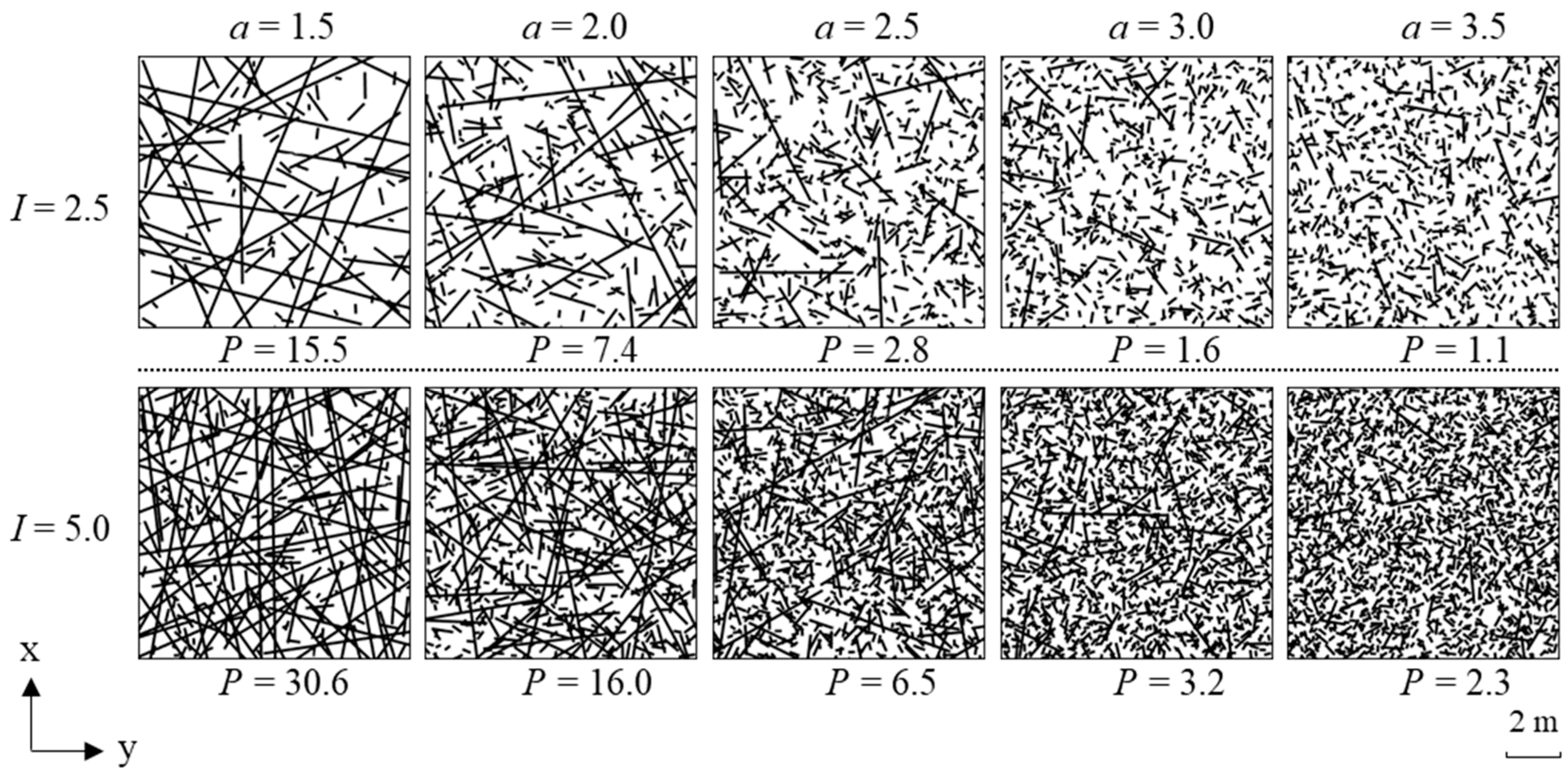
2.3. Discrete Fracture Network Generation

Due to the extremely low porosity of the permeability of the rock matrix, fractures induced via hydraulic fracturing were the main paths for the heat transfer of the working fluid in the reservoir. To more accurately characterize heat transfer through fractures, the discrete fracture network model was proposed and applied to deal with the anisotropic distribution of the fracture network and interactions between the fracture and rock matrix. Furthermore, the reflection of fractures in the reservoir needed fractal characteristics, including fracture lengths, fracture densities, and fracture connectivity [34,35,36]. The relationship between the number of fractures and fracture lengths is expressed in the following equation [37]:
n l , L = α L D l a ,   l [ l min , l max ]
where n(l, L) is the number of fractures with sizes l falling within the interval [l, l +dl](dl << l), L is the modeling domain, D is the fractal dimension, a is the fracture length index, α is a constant related to the fracture density, lmin is the minimum length of the fractures in a square box, and lmax is the maximum length of the fractures in a square box.
The fracture density I and fracture penetration coefficient P were calculated via the following equations:
I = 1 L 2 A L n ( l , L ) l d l
P = 1 L 2 A L n ( l , L ) l 2 d l
where l′ is the fracture length within the area of AL = L2, and the percolation parameter P is a statistical parameter that characterizes the connectivity of the fracture network. Generally, when P exceeds a penetration threshold of Pc (Pc ≈ 5.8), a through–through flow channel begins forming between the left and right boundaries of the fracture network.

3. Numerical Simulations

3.1. Discrete Fracture Network Generation

In order to reduce computational loads, a 2D discrete fracture network was applied in this study. A square domain with the size L = 10 m was generated. The limits of the fracture length were given by lmin = L/50 = 0.2 m and lmax = 50 L = 500 m. The directions and positions of the fractures were set to be random, and the fractal dimension was fixed at D = 2.0. At the same time, five different fracture length exponent cases, i.e., a = 1.5, 2.0, 2.5, 3.0, and 3.5, and two different mean fracture identity scenarios, i.e., I = 2.5 and 5.0 m−1, were considered. Moreover, for each combination of a and I, 10 realizations were generated. Figure 1 shows an example of a fracture network generated over 10 iterations with different characteristic parameters. We observed that when a was very small, the system was occupied by a large number of long fractures; in contrast, when a was very large, small fractures were mainly distributed in the system. Table 1 shows the left–right transfixion of fractures used in this study. When I = 5.0, a = 2.5 and 3.0, and the fracture network was partially connected and partially disconnected in the 10 repeated generation experiments.

3.2. Material Properties and Boundary Conditions

The numerical simulations were solved using COMSOL Multiphysics 5.6. The pressure boundary was set as constant conditions. The left boundary was set as the injection side with a pressure of 77.90 MPa, and the right boundary was set as the production side with a pressure of 77.47 MPa. The top and bottom boundaries are impermeable. As for the initial temperature conditions, the initial temperatures of the reservoir and original fluids in the reservoir were equal to 200 °C, and the injection temperature on the left side was 20 °C. In the stress field, fixed constraints were noted around the reservoir, and the disturbance of the fluid pressure and temperature in the in situ stress field was only investigated without considering the effect of the original in situ stress.
In this study, CO2 and water were used as working fluids for geothermal energy extraction. The properties of these fluids changed in line with the changes in temperature during the heat extraction process, while the pressure ranged between 77.47 and 77.90 MPa; thus, we assumed that it had few effects on the fluid properties.
The density and viscosity of the water were calculated as follows:
1 / ρ f = 3.086 0.899017 ( 4014.15 T ) 0.147166 0.39 ( 658.15 T ) 1.6 ( p 225.5 ) + δ
υ = 0.01775 1 + 0.033 T + 0.000221 T 2
where T is the absolute temperature of the water; δ is the function of water temperature and pressure, usually less than 6% of 1/pf; and υ is the kinematic viscosity of water.
Compared to water, the density and viscosity of CO2 more greatly varied with pressure and temperature, and specific values were calculated using CMG Winprop 2023.20.
In addition, the specific heat capacity of water and CO2 was a function of temperature, and the specific correlation was calculated using the following empirical formulas:
C H 2 O = 4086.2 0.3403 T + 0.0004 T 2 + 2 × 10 5 T 3
C C O 2 = 1759.8 + 7.4 T 0.05 T 2
The unit of heat capacity in this formula is J/kg/K. Other parameters for numerical simulations are listed in Table 2.

4. Results and Analysis

Figure 2 shows the effective permeability curves for different heat transfer working media during the heat extraction process. When no flow exists in the reservoir, the effective permeability is very close to the permeability of the rock matrix, and it remains unchanged during the development process. Once the reservoir is full of the working fluids, the effective permeability gradually increases. During the development process, due to the induced pressure of the flowing fluids in the fracture and the contraction effect of the rock, the fracture expands under tensile stress; consequently, the permeability of the fracture increases. Therefore, the effective permeability of the reservoir shows a gradually rising trend, as observed in Figure 2. While the heat energy of the reservoir rock reduces to a critical point, we found that the curves of the effective permeability for different discrete fracture networks reach the largest value and remain stable. Comparing the use of CO2 and water as the working fluid, CO2 reaches a steady state faster than water. In addition, different discrete fracture networks correspond to different effective permeability curves, which are not affected by the working fluids.
Figure 3 shows the relationship between the effective permeability and penetration coefficient of the fracture networks at the start and end of the simulation. In Figure 3, the ordinates of the embedded micrograph use a logarithmic scale. The blue marks represent the discrete fracture network with a fracture density of I = 2.5, and the red marks represent the discrete fracture network with a fracture density of I = 5. The larger the fracture density I, the larger the penetration of the coefficient P and the smaller the length index a of the fracture network. A positive correlation exists between the effective permeability and the penetration coefficient at the start and end of the simulation. When the discrete fracture network does not form a through-passage (P < Pc), the effective permeability is almost the same as the permeability of the rock matrix. However, when the fracture network begins forming a through-passage (P > Pc), the effective permeability sharply increases. At the end of the simulation, the effective permeability is about six times higher than that of the original state, mainly due to the thermal expansion coefficient and the values of the length index.
Figure 4 shows the temperature distributions of the reservoir for different discrete fracture networks with two parameters, i.e., the fracture density I and the length index a. The area of low temperature when the fracture density I = 2.5 is much larger than that for the fracture density I = 5.0. It is clear that the low-temperature area becomes smaller in line with the increase in the length index (ranging from 1.5 to 3.5). The above statements reflect the fact that a larger fracture density and smaller length index improved the connectivity of the discrete fracture network. As shown in Figure 4, when CO2 was the working fluid, the low-temperature area was obviously larger than that noted when water was the working fluid. However, at crack length indices a > 3.0, the cold region of CO2 is relatively smaller than that of water. In addition, the low-temperature front when CO2 was the working fluid was sharper than that noted when water was the working fluid. For this reason, it is better to use CO2 as the working fluid to carry heat.
Although geothermal resources are renewable resources, reservoir temperatures drop sharply after a period of geothermal energy production. Previous studies have highlighted an average drop in the reservoir temperature of 10 °C or a 10% drop in the production temperature as the best point at which to stop system operations [38,39]. Therefore, the analysis of outlet temperature and system thermal recovery is critical for the evaluation of the EGS operation.
Figure 5 and Figure 6 show the changes in outlet temperature and thermal recovery for different discrete fracture networks. When the working fluid is not being injected into the reservoir, the outlet temperature only depends on the heat conduction in the reservoir rock. Consequently, the curves related to outlet temperature and thermal recovery remain stable at the initial time. After the working fluid is injected, the convective heat transfer that describes the heat transfer between the working fluid and the fracture surface will accelerate the extraction of heat from the reservoir. We observed that fracture characteristics have a significant effect on the heat transfer in the reservoir. For example, when the penetration coefficient is P = 7.4 or P = 15.5, the thermal breakthrough time has a long tail effect [39]. For the same discrete fracture network, the long tail effect of CO2 when used as the working fluid is greater than that of water.
To better characterize the thrust effect of the low-temperature area, we plotted the change in the rock outlet temperature with thermal recovery (Figure 7). The curves show that a gradual decrease in outlet temperature occurs as the thermal recovery increases. For the same discrete fracture network, when the production temperature drops by 10%, the thermal recovery of CO2 is lower than that of water, indicating that the thermal sweeping efficiency of water is higher when the production heat is exploited, mainly due to the small flow of water and sufficient heat exchange in the rock matrix.
As shown in Figure 8, the thermal recovery factor for different discrete fracture networks at an outlet temperature of γT = 180 °C is plotted, where the blue region represents the fracture network with no flow and the red region represents the fracture network with flowing fluids. If γT = 180 °C increases, this means that, in the critical period of geothermal development (T > 180 °C), more geothermal energy is produced from the reservoir. When no flowing fluid is present in the reservoir, the thermal recovery efficiency is about 41% for an outlet temperature of 180 °C. When the working fluid begins to form into the reservoir, γT = 180 °C increases with the increase in the penetration coefficient P. We also noted that although the value of γT = 180 °C is higher than that of CO2 when water is used as the working fluid, the differences between water and CO2 gradually decrease with the increase in P, indicating that the higher the connectivity of the fractures, the larger the sweeping area of the flowing fluids.
In Figure 9, the heat extraction rates for different discrete fracture networks are presented. Initially, the heat extraction rate for CO2 as the working fluid is nearly three times higher than that recorded when water is used as the working fluid under the same pressure difference between the injection and production, indicating that CO2 is a more efficient working fluid, while due to higher flow rates, the heat capacity of CO2 is much lower than that of water. At the early stage of geothermal energy production, the outlet temperature remains unchanged, and the continuous expansion of the fractures increases the flow rate of the working fluid, leading to a gradual increase in the heat extraction rate. In addition, the maximum heat extraction rate when using CO2 as the working fluid is about 2.3 times that of CO2 at the initial state, while that of water is about 1.7 times higher. Then, the outlet temperature decreases, sharply reducing the heat extraction rate due to the thermal breakthrough until the outlet temperature reaches 20 °C, which is the same as the inlet temperature. We noted that the outlet temperature is about 180 °C, while the heat extraction rate reaches the maximum value, indicating that it is the best method of geothermal energy production.

5. Discussion and Conclusions

In this study, a discrete fracture network model that mainly considers the fracture density and the length index was successfully developed by integrating the thermal–hydraulic–mechanical coupled process. The heat transfer processes of two working fluids (CO2 and water) through different discrete fracture networks were simulated and evaluated.
Based on the simulation results, we found that there was a positive correlation between the effective permeability and the penetration coefficient at the start and the end of the simulation process. In addition, a larger fracture density and a smaller length index improved the connectivity of the discrete fracture network, indicating that fracture characteristics have a significant, direct effect on heat transfer in the reservoir. Through comparisons of different discrete fracture networks, we observed that the low-temperature area for CO2 as the working fluid was larger than that for water as the working fluid, while the low-temperature front for CO2 as the working fluid was sharper than that for water as the working fluid.
A detailed evaluation was performed for the thermal breakthrough of the geothermal energy production process. A 10% drop in the initial reservoir temperature was set as the critical outlet temperature (180 °C). It was obvious that the heat extraction rate reached the maximum value, meaning that the best mode for geothermal energy production was noted when the outlet temperature was about 180 °C. Furthermore, the maximum heat extraction rate when CO2 was used in the working fluid was about 2.3 times higher than that of CO2 at the initial state, while that of water was about 1.7 times higher.
This study provides a comprehensive analysis of the influence of the fracture density and fracture length index on heat transfer during the EGS process, which reflects the real conditions in the reservoir. However, in this paper, we mainly considered the mechanism model, while the analysis of parameters of the actual geothermal reservoir had certain deficiencies, as did the analysis of the real heat extraction process. In a future study, we will integrate the real parameters to study the characteristics of discrete fracture networks in EGSs in more detail.

Author Contributions

Conceptualization, Z.S.; Investigation, H.Z.; Data curation, X.L.; Writing—original draft, W.S.; Writing—review & editing, S.X. and H.N. All authors have read and agreed to the published version of the manuscript.

Funding

The authors would like to acknowledge the support provided by the National Key Research and Development Program of China (grant No. 2019YFB1504204).

Data Availability Statement

Data are contained within the article.

Conflicts of Interest

Author Shuang Xie was employed by the company Northwest Oil Field Branch of Sinopec. And Author Haifeng Nie was employed by the company Tarim Oilfield Company. The remaining authors declare that the research was conducted in the absence of any commercial or financial relationships that could be construed as a potential conflict of interest.

References

  1. Johnston, I.W.; Narsillo, G.A.; Colls, S. Emerging geothermal energy technologies. KSCE J. Civ. Eng. 2011, 15, 643–653. [Google Scholar] [CrossRef]
  2. William, E.G. Geothermal Energy: Renewable Energy and the Environment; CRC Press: Boca Raton, FL, USA, 2010. [Google Scholar]
  3. BP plc. Statistical Review of World Energy; BP: London, UK, 2021. [Google Scholar]
  4. Xu, T.; Zhang, Y.; Zeng, Z.; Bao, X. Technology Progress in an Enhanced Geothermal System (Hot Dry ROCK). Sci. Technol. Rev. 2012, 30, 42–45. [Google Scholar]
  5. Wang, X.; Wu, N.; Su, Z.; Zeng, Y. Progress of the enhanced geothermal systems (EGS) development technology. Prog. Geophys. 2012, 27, 15–22. [Google Scholar]
  6. Kelkar, S.; Woldegabriel, G.; Rehfeldt, K. Lessons learned from the pioneering hot dry rock project at Fenton. Geothermics 2016, 63, 5–14. [Google Scholar] [CrossRef]
  7. Buscheck, T.A.; Bielicki, J.M.; Chen, M.; Sun, Y.W.; Hao, Y.; Edmunds, T.A.; Randolph, J.B.; Saar, M.O. Multi-fluid sedimentary geothermal energy systems for dispatchable renewable electricity. In Proceedings of the World Geothermal Congress, Melbourne, Australia, 19–25 April 2015. [Google Scholar]
  8. Xu, T.F.; Pruess, K.; Apps, J. Numerical studies of fluid-rock interactions in Enhanced Geothermal Systems (EGS) with CO2 as working fluid. In Proceedings of the Thirty-Third Workshop on Geothermal Reservoir Engineering, Stanford University, Stanford, CA, USA, 28–30 January 2008. SGP-TR-185. [Google Scholar]
  9. Olasolo, P.; Juarez, M.C.; Morales, M.P.; Sebastiano, D.A.; Liarte, I.A. Enhanced geothermal systems (EGS): A review. Renew. Sustain. Energy Rev. 2016, 56, 133–144. [Google Scholar] [CrossRef]
  10. Zhang, F.Z.; Jiang, P.X.; Xu, R.N. System thermodynamic performance comparison of CO2-EGS and water-EGS systems. Appl. Therm. Eng. 2013, 61, 236–244. [Google Scholar] [CrossRef]
  11. Borgia, A.; Oldenburg, C.M.; Zhang, R.; Pan, L.H.; Daley, T.M.; Finsterle, S.; Ramakrishnan, T.S. Simulation of CO2 injection into fractures and faults for improving their geophysical characterization at EGS sites. Geothermics 2017, 69, 189–201. [Google Scholar] [CrossRef]
  12. Fox, D.B.; Koch, D.L.; Tester, J.W. An analytical thermos hydraulic model for discretely fractured geothermal reservoirs. Water Resour. Res. 2016, 52, 6792–6817. [Google Scholar] [CrossRef]
  13. Sun, Z.; Zhang, X.; Xu, Y.; Yao, J.; Wang, H.; Lv, S.; Sun, Z.; Huang, Y.; Cai, M.; Huang, X. Numerical simulation of the heat extraction in EGS with thermal-hydraulic-mechanical coupling method based on discrete fractures model. Energy 2017, 120, 20–33. [Google Scholar] [CrossRef]
  14. Borgia, A.; Pruess, K.; Kneafsey, T.J.; Oldenburg, C.M. Pan l. Numerical simulation of salt precipitation in a fractured CO2-Enhanced geothermal system. Geothermics 2012, 44, 13–22. [Google Scholar] [CrossRef]
  15. Juliusson, E.; Horne, R.N. Optimization of injection scheduling in fractured geothermal reservoirs. Geothermics 2013, 48, 80–92. [Google Scholar] [CrossRef]
  16. Li, J.W.; Sun, Z.X.; Jiang, C.Y.; Cherubini, C.; Scheuermann, A.; Galindo Torres, S.A.; Li, L. Investigations of heat extraction for water and CO2 flow based on the rough-walled discrete fracture network. Energy 2019, 189, 116184. [Google Scholar] [CrossRef]
  17. Asai, P.; Panja, P.; Velasco, R.; Mclennan, J.; Moore, J. Fluid flow distribution in fractures for a doublet system in Enhanced Geothermal Systems (EGS). Geothermics 2018, 75, 171–179. [Google Scholar] [CrossRef]
  18. Pruess, K. Enhanced geothermal systems (EGS) using CO2 as working fluid—A novel approach for generating renewable energy with simultaneous sequestration of carbon. Geothermics 2006, 35, 351–367. [Google Scholar] [CrossRef]
  19. Jiang, F.; Chen, J.; Huang, W.; Luo, L. A three-dimensional transient model for EGS subsurface thermo-hydraulic process. Energy 2014, 72, 300–310. [Google Scholar] [CrossRef]
  20. Talybov, M.A.; Abdulagatov, M.I. High-temperature and high-pressure PVT measurements and derived thermodynamics properties of geothermal fluids from East Turkey. Geothermics 2021, 95, 102125. [Google Scholar] [CrossRef]
  21. Pruess, K. On production behavior of enhanced geothermal systems with CO2 as working fluid. Energy Convers. Manag. 2008, 49, 1446–1454. [Google Scholar] [CrossRef]
  22. Remoroza, A.; Doroodchi, E.; Behdad, M. CO2-EGS in hot dry rock: Preliminary results from CO2-Rock interaction experiments. In Proceedings of the Thirty-Seventh Workshop on Geothermal Reservoir Engineering, Stanford, CA, USA, 30 January–1 February 2012. [Google Scholar]
  23. Wang, C.L.; Cheng, W.L.; Nian YLe Yang, L.; Han, B.B.; Liu, M.H. Simulation of heat extraction from CO2-based enhanced geothermal systems considering CO2 sequestration. Energy 2018, 142, 157–167. [Google Scholar] [CrossRef]
  24. Jiang, P.X.; Zhang, L.; Xu, R.N. Experimental study of convective heat transfer of carbon dioxide at supercritical pressures in a horizontal rock fracture and its application to enhanced geothermal systems. Appl. Therm. Eng. 2017, 117, 39–49. [Google Scholar] [CrossRef]
  25. Zhang, L.; Jiang, P.X.; Wang, Z.; Xu, R.N. Convective heat transfer of supercritical CO2 in a rock fracture for enhanced geothermal systems. Appl. Therm. Eng. 2017, 115, 923–936. [Google Scholar] [CrossRef]
  26. Duan, X.-Y.; Huang, D.; Lei, W.-X.; Chen, S.-C.; Huang, Z.-Q.; Zhu, C.-Y. Investigation of Heat Extraction in an Enhanced Geothermal System Embedded with Fracture Networks Using the Thermal–Hydraulic–Mechanical Coupling Model. Energies 2023, 16, 3758. [Google Scholar] [CrossRef]
  27. Yin, H. Theoretical and Experimental Study on Sustainable Heat Extraction from Hydrothermal Geothermal Based on Multi-Scale Entropy; Tianjin University: Tianjin, China, 2022. [Google Scholar]
  28. Yuan, X. Numerical Simulation of Seepage Heat Transfer in Deep Artificial Fissures Based on Discrete Elements; Jilin University: Changchun, China, 2022. [Google Scholar]
  29. Zhao, Y. Performance Analysis of Water and CO2 Heat Extraction from Supercritical Geothermal System; Jilin University: Changchun, China, 2023. [Google Scholar]
  30. Saeid, S.; Al-Khoury, R.; Barends, F. An efficient computational model for deep low-enthalpy geothermal systems. Comput. Geosci. 2013, 51, 400–409. [Google Scholar] [CrossRef]
  31. Chen, B.G.; Song, E.X.; Cheng, X.H. A numerical method for discrete fracture network model for flow and heat transfer in two-dimensional fractured rocks. Chin. J. Rock Mech. Eng. 2014, 33, 43–51. (In Chinese) [Google Scholar]
  32. Xu, C.; Dowd, P.A.; Tian, Z.F. A simplified coupled hydro-thermal model for enhanced geothermal systems. Appl. Energy 2015, 140, 135–145. [Google Scholar] [CrossRef]
  33. Louis, C. Rock Hydraulics in Rock Mechanics; Springer: New York, NY, USA, 1974; pp. 299–387. [Google Scholar]
  34. Yao, J.; Zhang, X.; Sun, Z.; Huang, Z.; Liu, J.; Li, Y.; Xin, Y.; Yan, X.; Liu, W. Numerical simulation of the heat extraction in 3D-EGS with thermal-hydraulic-mechanical coupling method based on discrete fractures model. Geothermics 2018, 74, 19–34. [Google Scholar] [CrossRef]
  35. Bour, O.; Davy, P. Connectivity of random fault networks following a power law fault length distribution. Water Resour. Res. 1997, 33, 1567–1584. [Google Scholar] [CrossRef]
  36. Darcel, C. Stereological analysis of fractal fracture networks. J. Geophys. Res. 2003, 108, 2451. [Google Scholar] [CrossRef]
  37. Watanabe, K.; Takahashi, H. Fractal geometry characterization of geothermal reservoir fracture networks. J. Geophys. Res. Solid Earth 1995, 100, 521–528. [Google Scholar] [CrossRef]
  38. Tester, J.W.; Anderson, B.J.; Batchelor, A.S.; Blackwell, D.D.; DiPippo, R.; Drake, E.M.; Garnish, J.; Livesay, B.; Moore, M.C.; Nichols, K.; et al. The Future of Geothermal Energy: Impact of Enhanced Geothermal Systems (EGS) on the United States in the 21st Century; MIT: Cambridge, MA, USA, 2006. [Google Scholar]
  39. Elsworth, D. A Comparative-Evaluation of the Parallel Flow and Spherical Reservoir Models of Hdr Geothermal Systems. J. Volcanol. Geotherm. Res. 1990, 44, 283–293. [Google Scholar] [CrossRef]
Figure 1. Example of a fracture network with different characteristic parameters.
Energies 17 00086 g001
Figure 2. Effective permeability for different discrete fracture networks (as shown in Figure 1) during the simulation: (a) CO2 and (b) water.
Energies 17 00086 g002
Figure 3. Relationship between effective permeability and penetration coefficient for the start and end of the simulation: (a) 0 s and (b) 109 s.
Energies 17 00086 g003
Figure 4. Temperature distributions for different discrete fracture networks: (a) CO2 and (b) water.
Energies 17 00086 g004
Figure 5. Outlet temperature for different discrete fracture networks: (a) CO2 and (b) water.
Energies 17 00086 g005
Figure 6. Thermal recovery for different discrete fracture networks: (a) CO2 and (b) water.
Energies 17 00086 g006
Figure 7. Outlet temperature and thermal recovery for different discrete fracture networks: (a) CO2 and (b) water.
Energies 17 00086 g007
Figure 8. Thermal recovery for different discrete fracture networks when the outlet temperature is 180 °C.
Energies 17 00086 g008
Figure 9. Heat extraction rate for different discrete fracture networks: (a) CO2 and (b) water.
Energies 17 00086 g009
Table 1. Left–right transfixion of fractures used in this study.
I = 2.5 m−1I = 5.0 m−1
aPProportion%aPProportion%
1.515.51001.530.6100
2.07.41002.016.0100
2.52.802.56.550
3.01.603.03.210
3.51.103.52.30
Table 2. Simulation parameters.
ParametersValue
Water thermal conductivity λ f w , W/m/K0
CO2 thermal conductivity λ f C O 2 , W/m/K0
Rock density ρ r o c k , kg/m32700
Rock heat capacity C S , J/kg/K1000
Rock thermal conductivity λ r o c k , W/m/K3
Rock matrix porosity ϕ 0.0001
Rock matrix permeability km, m21.0 × 10−18
Convection heat transfer coefficient h , W/m2/K3000
Gravity acceleration g , m/s29.8
Elastic modulus E , GPa30
Poisson ratio η 0.25
Thermal expansion coefficient α T , K−11.0 × 10⁶
Biot’s constant α B 1
Normal stiffness κ n , GPa/m1200
Tangential stiffness κ T , GPa/m400
Matrix storage coefficient S m , 1/Pa1.0 × 10−8
Fracture storage coefficient S f , 1/Pa1.0 × 10−9
Disclaimer/Publisher’s Note: The statements, opinions and data contained in all publications are solely those of the individual author(s) and contributor(s) and not of MDPI and/or the editor(s). MDPI and/or the editor(s) disclaim responsibility for any injury to people or property resulting from any ideas, methods, instructions or products referred to in the content.

