Article

A Novel Voltage Sensorless Estimation Method for Modular Multilevel Converters with a Model Predictive Control Strategy

1
School of Electrical Engineering, Southeast University, Nanjing 210096, China
2
Jiangsu Provincial Key Laboratory of Smart Grid Technology and Equipment, Southeast University, Nanjing 210096, China
*
Author to whom correspondence should be addressed.
Energies 2024, 17(1), 61; https://doi.org/10.3390/en17010061
Submission received: 20 November 2023 / Revised: 11 December 2023 / Accepted: 19 December 2023 / Published: 21 December 2023
(This article belongs to the Special Issue Advances in Modelling and Control of Power Converters)

Abstract

:
This paper proposes a novel voltage estimation scheme for the modular multilevel converter (MMC) based on model predictive control (MPC). The developed strategy is presented by combining a disturbance observer (DOB) with an adaptive neural network (ANN) for voltage estimation in the MMC. Firstly, the ac-side and dc bus voltages are estimated as the disturbance items of the DOB which acts as the cost function during each control cycle and ensures the minimal computational cost. Then, the submodule (SM) capacitor voltage estimation is achieved based on the ANN with the estimated ac-side and dc bus voltages. The proposed method requires only one current sensor per arm and has a simple structure with three weights to be adjusted. Comprehensive simulation studies and experiments are presented to demonstrate its effectiveness and feasibility. The results indicate that the proposed method has a high accuracy, a fast dynamic response, and no effects on the original MPC performance.

1. Introduction

The modular multilevel converter (MMC) technology provides high efficiency, dynamic performance, and low harmonic distortion, which contribute to power quality and grid stability [1,2,3,4]. With its modular design, the MMC offers scalability and easy maintenance, making it highly applicable in high-voltage direct current, flexible ac transmission systems, electric vehicle charging, energy storage, and railway power supply [5,6,7,8,9,10]. However, the modular architecture depends on sub-module (SM) balancing control which is one of the most reported concerns of the MMC. Although various control solutions have been proposed [11,12,13,14], these methods depend on the real-time measurement of individual SM capacitor voltages. As typical MMC control strategies use a centralized controller, a high number of SMs significantly increases the complexity of the measurement and communication functions of the control system. In addition, a large number of voltage sensors and communication lines also lead to higher manufacturing costs.
In practice, decreasing the converters’ cost can improve their competitiveness [15]. Besides obvious benefits of sensor reduction, there are several other advantages such as elimination of noise, resolution limitations, offsets and various disturbances related to sensors, and a decrease in hardware complexity. Nevertheless, even if sensors are installed, a control scheme with the capability for sensorless operation is still relevant [16,17]. This ensures that the operation will not be interrupted in the event of a sensor failure. The ac-side current and arm current sensors are essential for the proper operation of the control system since they are the controlled quantities. In addition, these sensors are employed for overcurrent protection. On the other hand, voltage sensors are mainly used for synchronization and voltage balancing purposes. So, they can be replaced by software sensors.
Several voltage estimation schemes have been considered to deal with the measurement complexity and improve the system reliability for the MMC. In [18], a method using a sliding mode observer and fuzzy control is introduced to estimate the capacitor voltage. It simplifies the hardware structure and reduces the need for voltage sensors. The approach is further explored in [19] with the development of a discrete-time sliding-mode observer that maintains stability and robustness of the observation, especially under dynamic conditions with parameter uncertainties. The number of voltage sensors is reduced by proposing an adaptive linear neuron algorithm-based capacitor voltage estimation method in [20]. It eliminates complex communication links with the central controller. An integrated strategy that takes into account drive system parameters for estimating and selecting the most suitable SM capacitors to precisely control capacitor voltage fluctuations is proposed in [21]. A grouping measurement strategy that periodically updates SM capacitance to increase the accuracy of voltage estimation and facilitates the detection and replacement of aging capacitors is adopted in [22]. In [23], only one voltage sensor per arm is required. It is combined with a recursive least squares algorithm to estimate the capacitor voltages. In [24], a voltage sensor per arm combined with a Kalman filter algorithm is used to achieve capacitor voltage estimation and balance. Furthermore, the arm voltage sensor is eliminated in [25]. A simplified online capacitance estimation method which only monitors the SM capacitor voltage variation at the fundamental frequency, eliminating the need for additional current/voltage injection steps, is introduced [26]. Meanwhile, a data transmission system that reconstructs the ac component of the SM capacitor voltages, allowing for only the dc component to be transmitted to the common bus, is studied [27]. In [28], an embedded real-time simulator is proposed for the voltage sensorless control of the MMC.
Recently, several investigations on model predictive control (MPC) concerning the elimination of sensors have been reported for the reliable operation of the MMC. Ref. [29] has developed a virtual-flux-based grid voltage sensorless direct MPC scheme for the grid-side MMC. An adaptive linear-neuron-based SM capacitor voltage estimation scheme with a currentless sorting-based capacitor-voltage-balancing approach is proposed in [30]. In [31], a current sensorless maximum power point tracking algorithm for a solar photovoltaic power station based on the MMC is designed.
While considerable efforts through existing methods have been focused on achieving the elimination or reduction of sensors for the MMC, they have not entirely eliminated the sensor requirement. Additional hardware is still needed such as arm voltage or ac-side voltage sensors. It cannot be neglected that the arm voltage or ac-side voltage of the MMC is usually much higher than the SM capacitor voltages, which also increases the cost and complexity of the system.
Motivated by the abovementioned observations, this paper proposes a novel voltage sensorless estimation method, which integrates a disturbance observer (DOB) and an adaptive neural network (ANN) algorithm. This method consists of three steps: the MPC obtains switching signals, the DOB observes the ac-side and dc bus voltages, and the ANN algorithm estimates the SM capacitor voltages. The DOB is based on the control process of the MPC, and the ANN algorithm is designed according to the results of the MPC and DOB. Thus, the sensorless control of the ac-side, dc bus, and SM capacitor voltages of the MMC system is achieved. The main contributions include:
(1)
The DOB realizes the estimation of the ac-side and dc bus voltages of the MMC system without sacrificing the performance of the original MPC. It is a simple structure with minimal order and low computational cost.
(2)
Using the ac-side and dc bus voltages estimated by the DOB and estimating the SM capacitor voltages through the ANN algorithm, the computational effort of this method does not significantly increase with the number of SMs.
(3)
Based on the MPC, the combination of the DOB and the ANN algorithm achieves voltage sensorless control for the MMC.
The proposed method was validated under simulations and an 8 kVA experimental prototype.

2. MPC Strategy of the MMC

The topology structure of the three-phase MMC main circuit and its SM are shown in Figure 1. It consists of six arms, and each phase contains upper and lower arms. Each arm contains N series-connected SMs and an arm inductor. Take phase a as an example and the subscript is neglected for simplification. Here, L 0 represents the arm inductance; u c , i represents the capacitor voltage of the i-th (1, 2, ..., 2N) SM; i p and i n represents the currents of the upper and lower arms; u p and u n represent the voltages of the upper and lower arms; U d c and i d c represent the voltage and current on the dc bus; i a c and u a c represent the ac-side current and voltage, respectively; T 1 and T 2 are the two power switching devices of the SM, while D 1 and D 2 are the corresponding anti-parallel diodes.
Using Kirchhoff’s circuit law, the following mathematical equations can be obtained: where i d i f f is the inner unbalance current.
L 0 d i p d t = U d c 2 u p u a c
L 0 d i n d t = U d c 2 u n + u a c
i p = i d i f f + i a c 2
i n = i d i f f i a c 2
Then, the dynamic equations of the ac loop and the dc loop can be obtained as:
L 0 d i a c d t = u p u n + 2 u a c
L 0 d i d i f f d t = U d c u p u n 2
Applying the forward Euler formula to (5) and (6), the discrete model of the MMCs can be obtained as follows:
i a c k + 1 = T s L 0 ( u p u n + 2 u a c ) + i a c k
i d i f f k + 1 = T s 2 L 0 ( U d c u p u n ) + i d i f f k
where T s is the sampling period.
Let the arm current i m = i p         o r         i n , the SM capacitor voltages can be written as:
When   SM   is   inserted : u c , i k + 1 = u c , i k + i m T s C When   SM   is   bypassed : u c , i k + 1 = u c , i k
where C is the SM capacitance.
In an MMC, the SM capacitor voltage balancing and circulating current suppression should be achieved simultaneously in addition to ac-side current control. The MPC can handle the multivariable control using cost functions. All the control objectives are optimized using the exhausted search algorithm. The switching combination with the lowest cost function value is applied to achieve optimal control of the control objectives. More details on the MPC of MMCs can be found in [11].
Assuming that the SM capacitor nominal voltage is U d c / N , the ac-side voltage reference can be expressed as follows:
u a c ref = u n ref u p ref 2
u p ref ,   u n ref = U d c N × 0 ,   1 ,   2 ,   ,   N 1 ,   N
where u a c ref is the ac-side voltage reference; u p ref and u n ref are the upper-arm and lower-arm voltage references, respectively.
Then, Equation (7) can be rewritten as follows:
i a c k + 1 = 2 T s L 0 ( u a c ref u a c ) + i a c k
According to Equations (10) and (12), the same voltage U d i f f added to the upper-arm and lower-arm voltage references does not affect the ac-side current. Hence, Equation (8) can be rewritten as follows:
i d i f f k + 1 = T s 2 L 0 [ U d c ( u p ref + U d i f f ) ( u n ref + U d i f f ) ] + i d i f f k
U d i f f = U d c N 1 ,   0 ,   1
The cost function is designed as follows:
J 1 = i a c ref i a c k + 1 J 2 = i d c ref / 3 i d i f f k + 1 J 3 = T s i m C ( u c , i k + 1 U d c N )
where J 1 is the cost function of the ac-side current control; J 2 is the cost function of circulating current suppression; J 3 is the cost function of SM capacitor voltage balancing; i a c ref and i d c ref are the reference values for the ac-side and dc bus currents, respectively. At the end of each control period, the switching combination is obtained. With the known applied switching combination, the proposed voltage estimation scheme is presented in Section 3.

3. The Proposed Voltage Estimation Scheme

In this section, an approach for the ac-side, dc bus, and SM capacitor voltage estimation of the MMC is presented. The proposed technique takes advantage of the IGBT switching states of SMs that are calculated by the MPC and requires no extra hardware. The proposed scheme is carried out in two steps: DOB-based ac-side and dc bus voltage estimation, and ANN-based SM capacitor voltage estimation. In the first stage, the ac-side and dc bus voltages are considered as the disturbances which can be estimated by the DOB. In the second stage, the ANN-based SM capacitor voltage estimation is achieved by the estimated ac-side and dc bus voltages in the first stage. By combining these two control methods, an MPC approach without voltage sensors for the MMC system is achieved.

3.1. AC-Side and DC Bus Voltage Estimation Based on DOB

Introducing disturbance terms in Equations (12) and (13), let x = [ i a c ,   i d i f f ] T , u = [ u a c ref ,   u p ref + u n ref + 2 U d i f f ] T , d = [ u a c ,   U d c ] T . Then, Equations (12) and (13) are normalized to be a linearized state-space model, which is described by the following:
x k + 1 = Φ x k + Γ u k + G d k , x 0 = x ( 0 ) y k = C x k
where x denotes the state variable of the system; u denotes the control input; d denotes the unknown disturbance of ac-side and dc bus voltages that needs to be observed; y denotes the measurement output; Φ , Γ , G and C denote the known parameter matrices, which are included in (Appendix A Equation (A1)).
The DOB applicable for voltage estimation in both the ac-side and dc bus of the MMC can be expressed using the following equation [32]:
d ^ k = K x k z k z k + 1 = z k + K [ ( Φ C ) x k + Γ u k + G d ^ k ]
where d ^ = [ u ^ a c ,   U ^ d c ] T is the estimation of d ; z is the state variable of the DOB; K is the gain matrix.
To prove the stability of the designed DOB, for state estimation error e k = d k d ^ k , one may show that:
e k + 1 = d k + 1 d ^ k + 1 = d k + 1 ( K x k + 1 z k + 1 ) = d k + 1 K ( Φ x k + Γ u k + G d k ) + z k + K [ ( Φ C ) x k + Γ u k + G d ^ k ] = d k + 1 ( K x k z k ) K G ( d k d ^ k ) = d k + 1 d k + d k ¯ ( K x k z k ) d ^ k K G ( d k d ^ k ) = Δ d k + 1 + ( E K G ) e k
where Δ d k + 1 = d k + 1 d k ; E is an identity matrix.
In fact, the stability of the DOB can be achieved if the pair ( E ,   G ) is observable. It is evident that the pair ( E ,   G ) is observable since rank ( E ) = rank ( G ) = 2 . Hence, it is always possible to estimate the disturbance within a bound when the full state is available.
Then, given a matrix Λ = d i a g [ λ 1 ,   λ 2 ] and λ i < 1   ( i = 1 ,   2 ) , K is designed as follows:
K = ( E q Λ ) G 1
It can be seen that the stability of the DOB is only related to the configuration of the parameter λ i . The order of the observer is equal to the number of disturbances, leading to the minimum order and low computation.

3.2. SM Capacitor Voltage Estimation Based on ANN

As the largest number of measurements are in an MMC system, it is difficult to achieve sensorless control for SM capacitor voltages using the DOB technique individually. The advantage of the ANN algorithm is that the computational complexity does not significantly increase with the number of SMs, which makes it more suitable for SM capacitor voltage estimation.
The estimated upper- and lower-arm voltages are given by:
u ^ p k = [ W ^ p k ] T S p k u ^ n k = [ W ^ n k ] T S n k
where u ^ p k is the estimation of u p k ; u ^ n k is the estimation of u n k ; W ^ p k = [ u ^ c , 1 k , u ^ c , 2 k , , u ^ c , N k ] T is the weight vector of the upper arm; W ^ n k = [ u ^ c , N + 1 k , u ^ c , N + 2 k , , u ^ c , 2 N k ] T is the weight vector of the lower arm; S p k = [ S 1 k , S 2 k , , S N k ] T is the switch state vector of the upper arm; S n k = [ S N + 1 k , S N + 2 k , , S 2 N k ] T is the switch state vector of the lower arm.
Substituting u ^ a c and U ^ d c into Equations (1) and (2), and applying the forward Euler formula, the upper- and lower-arm voltages can be derived as follows:
u p k = U ^ d c 2 L 0 i p k i p k 1 T s u ^ a c k u n k = U ^ d c 2 L 0 i n k i n k 1 T s + u ^ a c k
Then, the estimated error of the upper- and lower-arm voltages can be given by:
e p k = u p k u ^ p k e n k = u n k u ^ n k
where e p k is the estimated error in the upper arm; e n k is the estimated error in the lower arm.
In order to minimize e p k and e n k , the least mean square algorithm based on the weight update rule is deployed as follows [15,33]:
W ^ p k + 1 = W ^ p k + μ s e p k S p k W ^ n k + 1 = W ^ n k + μ s e n k S n k
where μ s is the learning rate ( 0 < μ s < 1 ).
The value of μ s is related to the stability of the learning process and should be chosen correctly based on actual testing. Therefore, the simple least mean square algorithm in Equation (23) is used for minimizing e p k and e n k online.
By combining the DOB-based ac-side and dc bus voltage estimation and ANN-based SM capacitor voltage estimation, the proposed voltage sensorless estimation method for the MMC is obtained, as shown in Figure 2. To be specific, this solution requires only one current sensor per arm to achieve the voltage estimation of the MMC without sacrificing the simplicity of the control structure and increasing costs.

4. Simulation and Experimental Verification

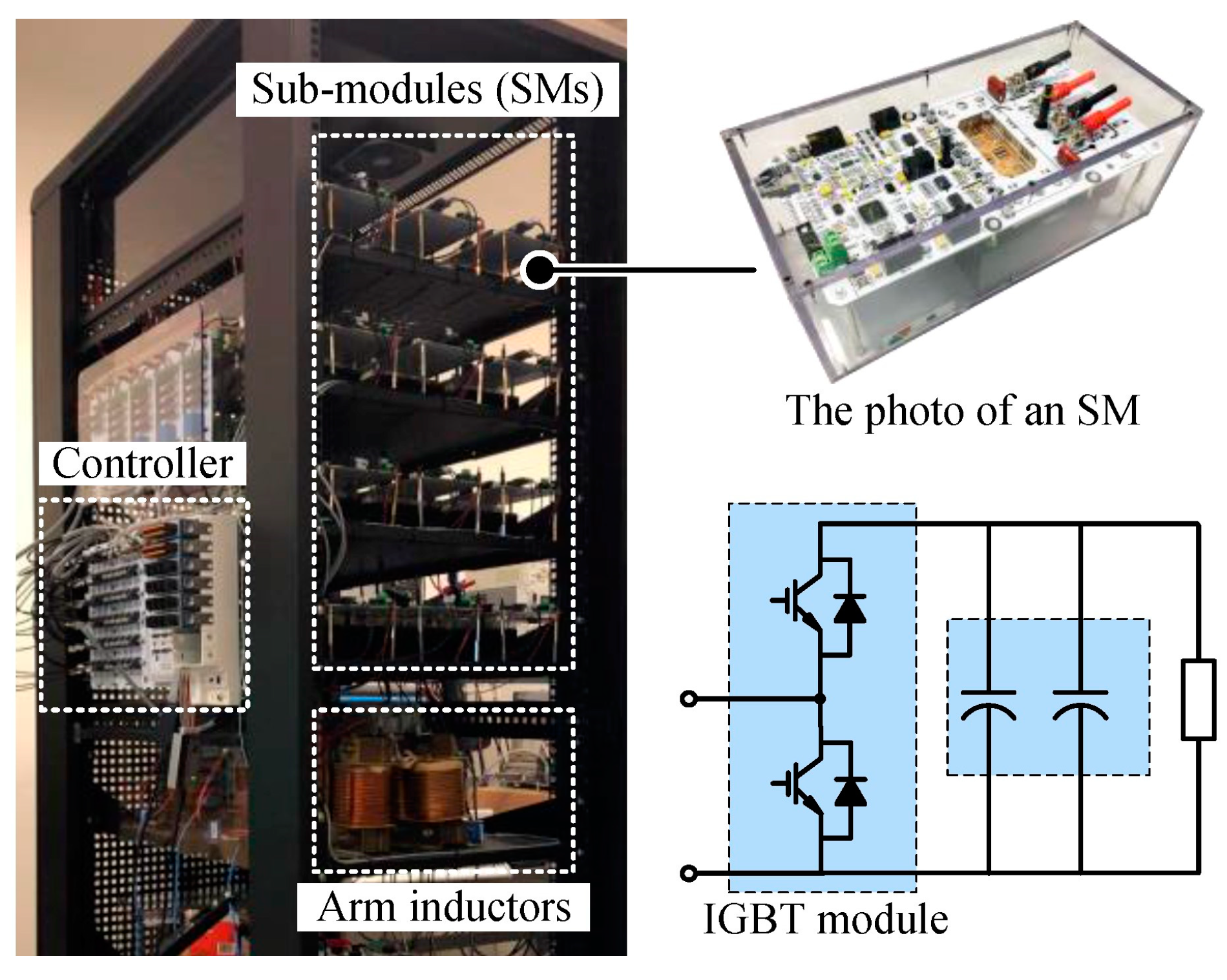
In order to verify the effectiveness of the proposed method, the simulation and experimental results are discussed in this section. An 8 kVA down-scale MMC prototype was built for the experimental verification, as shown in Figure 3. Table 1 indicates the design parameters of the system.

4.1. Simulation Verification

4.1.1. Simulation Results of DOB-Based ac-Side and dc Bus Voltage Estimation

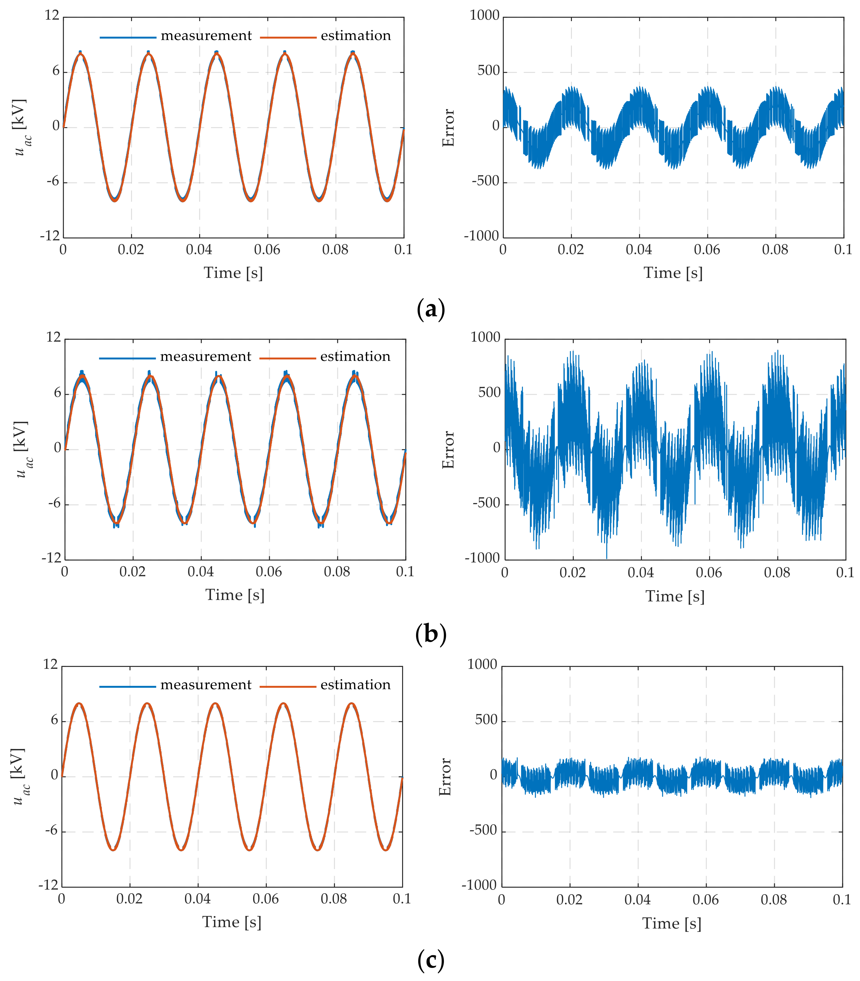
The first step verifies the effectiveness of the ac-side and dc bus voltage estimation by the proposed DOB method in the simulation. The inductance mismatch can affect the performance of the MPC, resulting in ripples in the ac-side current [8,34,35]. Therefore, to verify whether the proposed algorithm will have an impact on the ac-side current, simulations were carried out with the actual arm inductance L being 1, 0.5, and 1.5 times the rated inductance L 0 , respectively. The fundamental component and the total harmonic distortion (THD) of the ac-side current were compared. As illustrated in Figure 4, regardless of the inductance variations, the estimated ac-side voltage consistently tracks the measured one with an estimation error maintained below 5%. It is worth pointing out that the ripple waves of the ac-side voltage are increased and reduced with L / L 0 = 0.5 and L / L 0 = 1.5 , respectively. However, the estimated one is almost unchanged under different inductances, which means that the estimated ac-side voltage is less affected by inductance mismatches. For the same reason, although the estimated error varies with the inductance mismatches, it is caused by the measured ac-side voltage ripples and does not degrade the performance of the DOB.
Figure 5 illustrates the fundamental component and the THD of the ac-side current. In the case of no inductance mismatches ( L / L 0 = 1 ), the fundamental component and the THD between the original method without the DOB and the DOB-based method are almost unchanged. When the inductance is overestimated ( L / L 0 = 0.5 ), both the fundamental component and the THD reduce slightly from 99.9 A and 1.93% to 99.83 A and 1.92%, respectively. When the inductance is underestimated ( L / L 0 = 1.5 ), the THD increases from 1.14% to 1.17%. This is because the ripple waves of the estimated ac-side voltage are smaller than the measured ones with L / L 0 = 0.5 while being larger than the measured one with L / L 0 = 1.5 . In general, the proposed DOB method can estimate the ac-side voltage effectively with no effect on the ac-side current.
The results of the measured and estimated dc bus voltages and the error between them is shown in Figure 6. The estimated value can be tracked stably by the measured one before 25 ms in the steady-state condition with an estimation error of 1.07%. Then, a step change from 1.0 p.u. to 0.9 p.u. of the dc bus voltage is introduced at 25 ms, and the estimated dc bus voltage drops from 1.0 p.u. to 0.9 p.u. within 1 ms.

4.1.2. Simulation Results of ANN-Based SM Capacitor Voltage Estimation

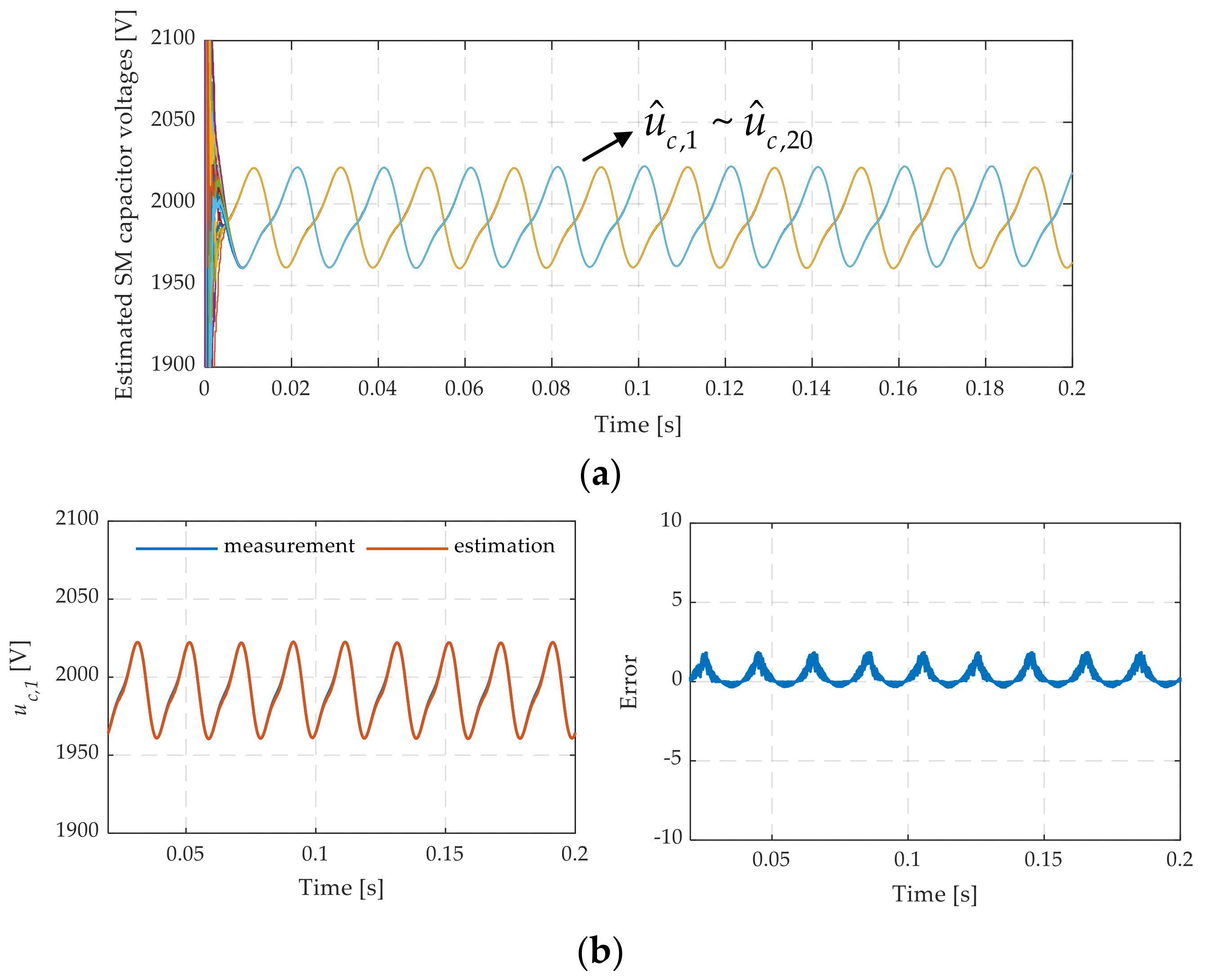
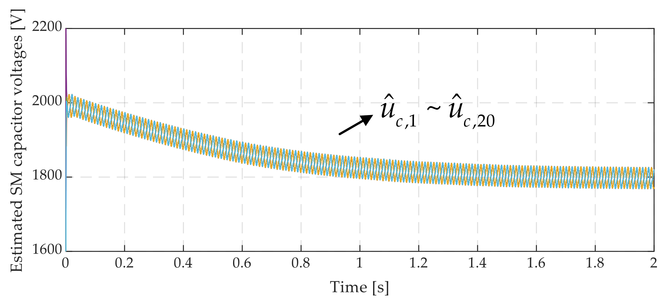
This section verifies the effectiveness of the ANN-based SM capacitor voltage estimation method in the simulation. As shown in Figure 7a, the SM capacitor voltages in the upper and lower arms are accurately estimated. The estimated 1st SM capacitor voltage is similar to the measured one with the error below 1%, as shown in Figure 7b. To evaluate the dynamic performance of the proposed solution, a step change is performed in the dc bus voltage from 1.0 p.u. to 0.9 p.u. Figure 8 indicates the good tracking performance of the estimated SM capacitor voltages. They are gradually decreased to 0.9 p.u. within 2 s.

4.2. Experimental Verification

4.2.1. Experimental Results of DOB-Based ac-Side and dc Bus Voltage Estimation

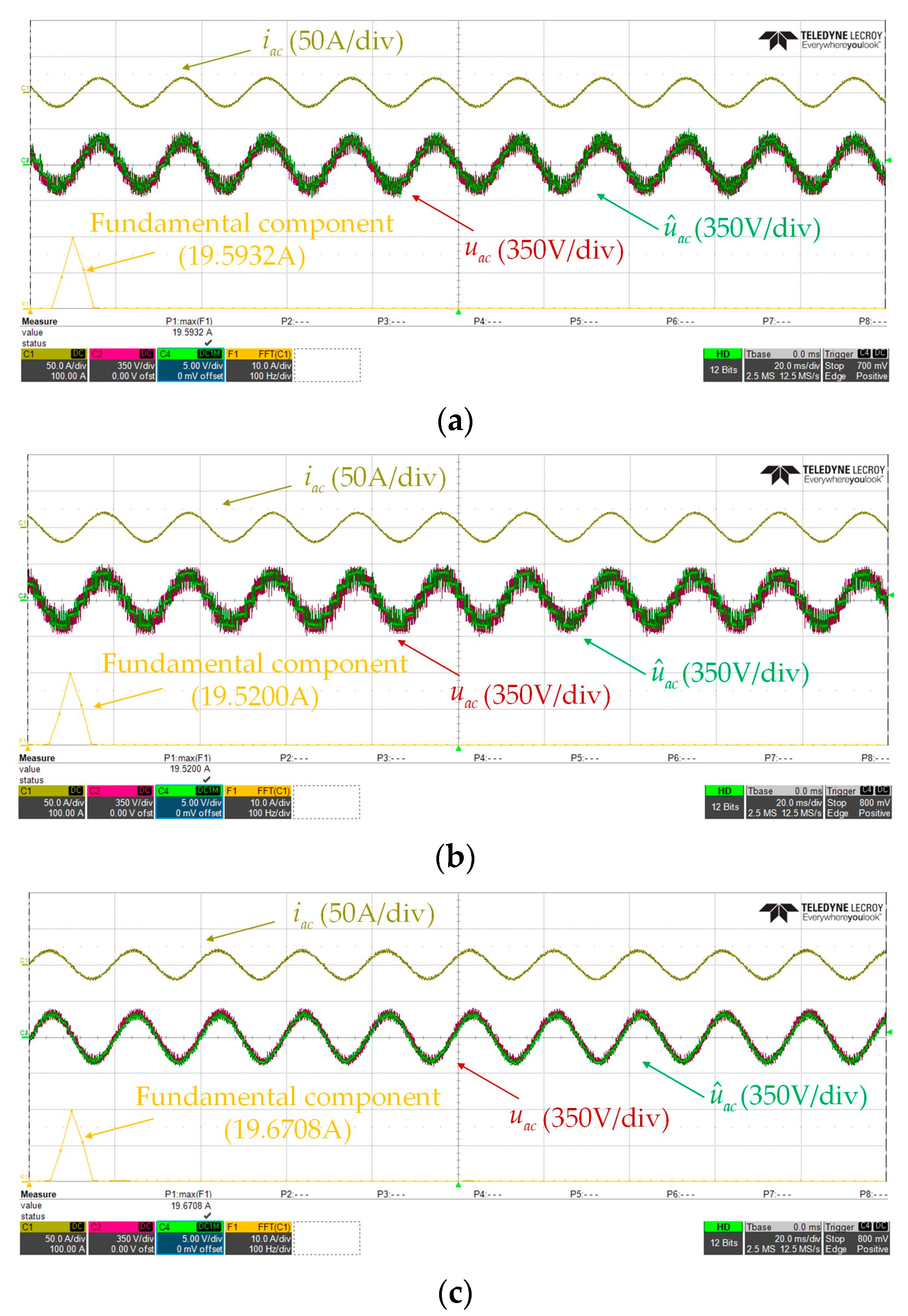
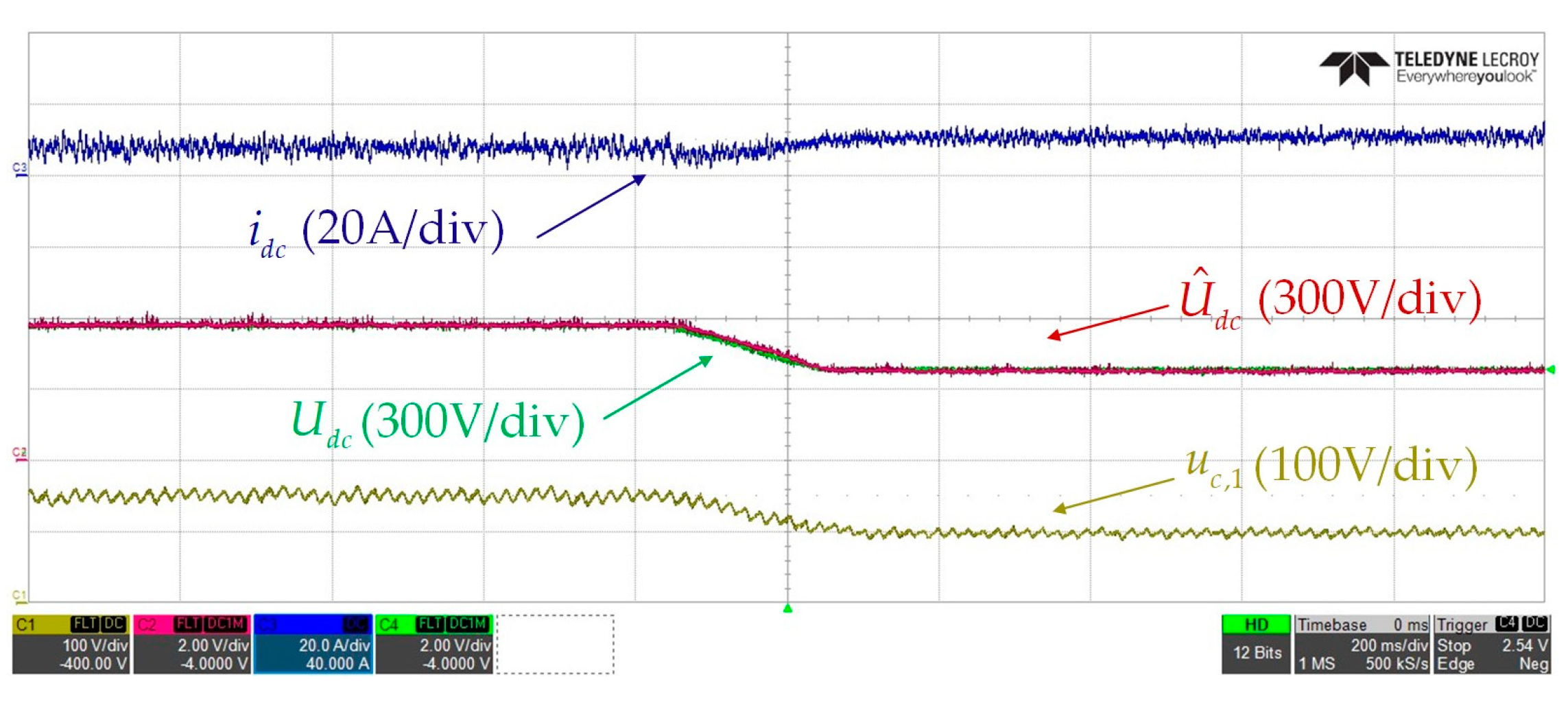
As shown in Figure 9, for the estimation of the ac-side voltage, the proposed DOB method can stably track the actual ac-side voltage under the arm inductance mismatch. Especially for the case with L / L 0 = 0.5 , the overvalued inductance causes larger ripple waves of the ac-side voltage and a lower fundamental component. However, the estimated signal is almost unaffected by inductance mismatch and presents smaller ripple waves. Benefiting from a higher actual arm inductance with L / L 0 = 1.5 , both measured and estimated ac-side voltages are smoother. The effects of the proposed method on the ac-side current are listed in Table 2. When the inductance is overestimated ( L / L 0 = 0.5 ), the THD of the ac-side current based on the DOB method reduces slightly compared to the original method, while in the other two cases, the values of the THD increases but do not exceed 7.00%. The dc bus voltage estimation is shown in Figure 10. The proposed method can accurately track the actual dc-side voltage in the steady-state. Reducing the dc bus voltage from 600 V to 400 V at 0.8 s, the proposed method still performs well under dynamic conditions.

4.2.2. Experimental Results of ANN-Based SM Capacitor Voltage Estimation

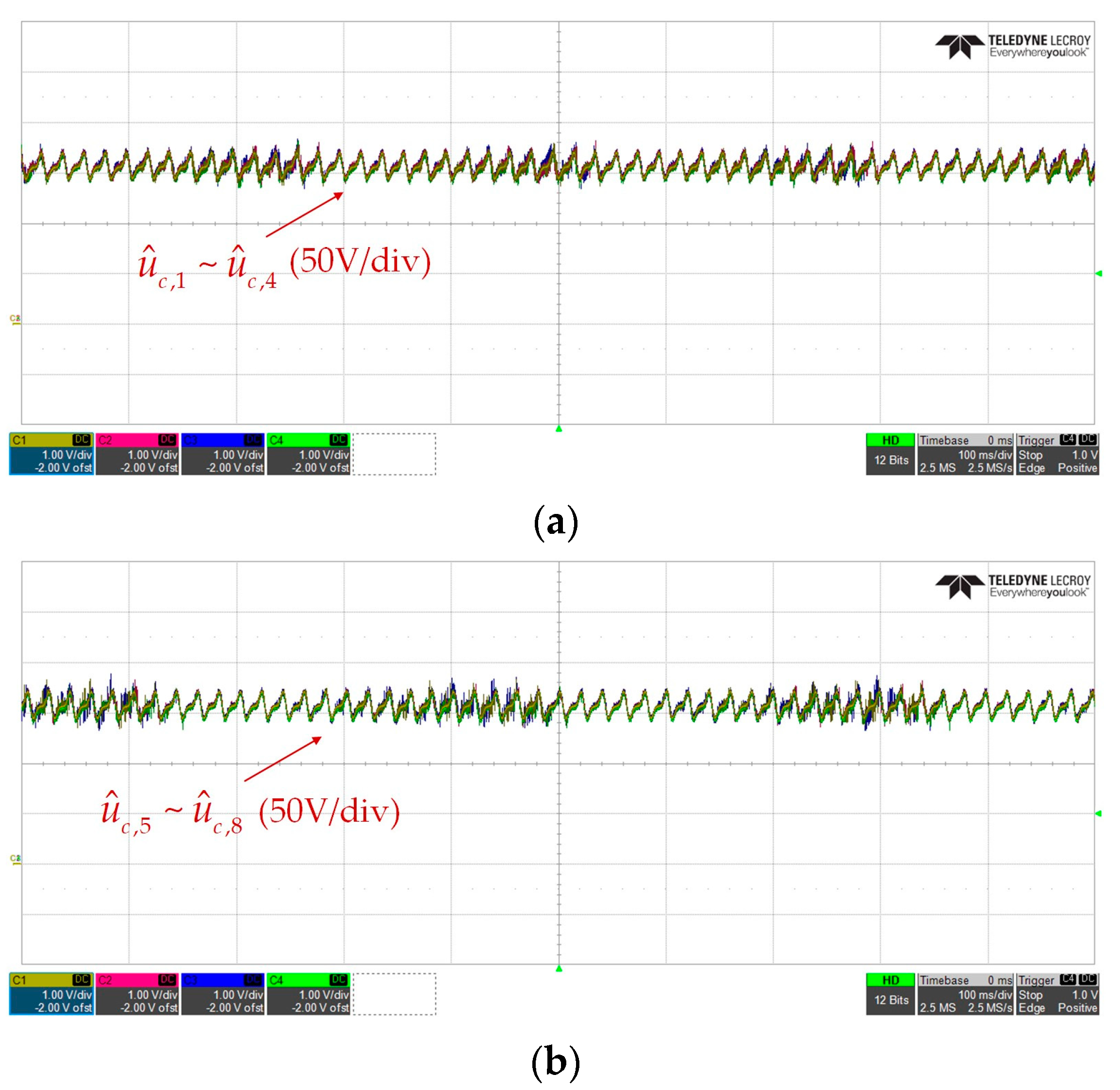
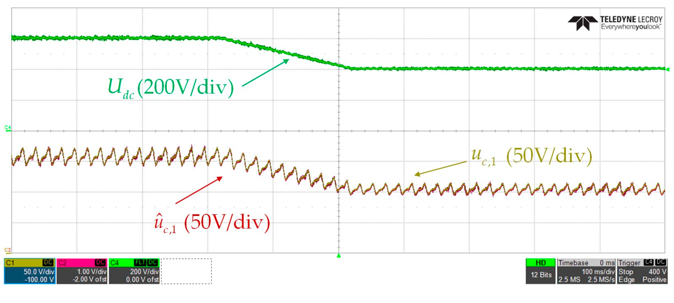
The experimental results of the proposed ANN-based SM capacitor voltage estimation are illustrated in Figure 11 and Figure 12. As can be clearly seen in Figure 11a,b, the SM capacitor voltages in the upper and lower arms under steady-state conditions are estimated precisely. Furthermore, all of the estimated SM capacitor voltages are balanced at around 150 V, which verifies that the proposed design is not only capable of accomplishing the SM voltage estimation but also achieves satisfactory SM capacitor voltage balancing control performance. To study the dynamic performance of the proposed method, the dc bus voltage is changed from 600 V to 400 V within 0.2 s, and the results are shown in Figure 12. Taking the 1st SM as an example, the estimated 1st SM capacitor voltage can track the measured one to drop from 150 V to 100 V, which indicates the fast transient-state response of the proposed method.

5. Conclusions

In this study, a new voltage estimation scheme for eliminating all the voltage sensors in the MMC is proposed. The holistic scheme encompasses three parts: an MPC strategy for the MMC, DOB-based ac-side and dc bus voltage estimation, and ANN-based SM capacitor voltage estimation. The DOB-based ac-side and dc bus voltage estimation is achieved by the cost functions of the MPC. Regarding the ac-side and dc bus voltages, as the disturbance terms needed to be observed, the DOB acts on the cost functions during each control cycle and ensures minimal order. Furthermore, with the known applied switching states of the MPC and the obtained estimated ac-side and dc bus voltages from the DOB, an ANN-based SM capacitor voltage estimation is designed. The ANN algorithm not only eliminates the need for measuring each SM capacitor voltage, but also has a fast dynamic response and high accuracy. Hence, the integrated voltage estimation method of the ac-side, dc bus, and SM capacitor voltages for the MMC is achieved. The reasonable structure requires only one current sensor per arm and offers a low computational burden where just three weights are adjusted.
The robustness of the proposed method regarding the step change in the dc bus voltage and the arm inductance mismatches was investigated through simulation and experimental tests. The obtained results demonstrate the high performance of the proposed voltage estimation scheme within the analyzed working conditions. In addition, the voltage estimation scheme will lead to reduced capital investments and less complexity of the hardware for MMCs. It is worth pointing out that the proposed methodology can be easily extended to higher voltage levels and more complex topologies without the restrictions resulting from computational burden. In addition, estimated errors still exist and are affected by the arm inductance mismatches, especially when the actual inductances are underestimated. This is worth exploring in future research.

Author Contributions

Investigation, Z.S.; Writing—original draft, Y.L.; Writing—review & editing, K.L. and H.Z.; Supervision, L.J., J.Y. and Z.X.; Funding acquisition, F.D. All authors have read and agreed to the published version of the manuscript.

Funding

This research was funded by National Key Research and Development Program of China, grant number 2022YFE0196300, Start-up Research Fund of Southeast University, grant number RF1028623299, National Natural Science Foundations of China, grant number 52207191, State Key Laboratory of Alternate Electrical Power System with Renewable Energy Sources, grant number LAPS21021, and Nanjing Science and Technology Innovation project for overseas students, grant number 4216002303.

Data Availability Statement

Data are contained within the article.

Conflicts of Interest

The authors declare no conflict of interest.

Appendix A

Φ = 1 0 0 1   , Γ = 2 T s L 0 0 0 T s 2 L 0   , G = 2 T s L 0 0 0 T s 2 L 0   , C = 1 0 0 1 .

References

  1. Arias-Esquivel, Y.; Cárdenas, R.; Tarisciotti, L.; Díaz, M.; Mora, A. A Two-Step Continuous-Control-Set MPC for Modular Multilevel Converters Operating with Variable Output Voltage and Frequency. IEEE Trans. Power Electron. 2023, 38, 12091–12103. [Google Scholar] [CrossRef]
  2. Huang, M. Submodule Capacitor Voltage Ripple Reduction of Full-Bridge Submodule-Based MMC (FBSM-MMC) with Non-Sinusoidal Voltage Injection. Energies 2023, 16, 4305. [Google Scholar] [CrossRef]
  3. Li, J.; Zhang, Z.; Li, Z.; Babayomi, O. Predictive Control of Modular Multilevel Converters: Adaptive Hybrid Framework for Circulating Current and Capacitor Voltage Fluctuation Suppression. Energies 2023, 16, 5772. [Google Scholar] [CrossRef]
  4. Yang, Q.F.; Ding, T.; He, H.X.; Chen, X.; Tao, F.B.; Zhou, Z.C.; Xu, Y.; Chen, S. Model predictive control of MMC-UPFC under unbalanced grid conditions. Int. J. Electr. Power Energy Syst. 2020, 117, 105637.1–105637.11. [Google Scholar] [CrossRef]
  5. Wang, C.; Xu, J.X.; Pan, X.W.; Gong, W.M.; Zhu, Z.; Xu, S.K. Impedance Modeling and Analysis of Series-Connected Modular Multilevel Converter (MMC) and its Comparative Study with Conventional MMC for HVDC Applications. IEEE Trans. Power Deliv. 2022, 37, 3270–3281. [Google Scholar] [CrossRef]
  6. Vural, A.M.; Wirsiy, E.N. Three-phase modular multilevel converter based unified power flow controller. Eng. Sci. Technol. Int. J. 2020, 23, 299–306. [Google Scholar] [CrossRef]
  7. Viatkin, A.; Ricco, M.; Mandrioli, R.; Kerekes, T.; Teodorescu, R.; Grandi, G. A Novel Modular Multilevel Converter Based on Interleaved Half-Bridge Submodules. IEEE Trans. Ind. Electron. 2023, 70, 125–136. [Google Scholar] [CrossRef]
  8. Liao, Y.; You, J.; Yang, J.; Wang, Z.; Jin, L. Disturbance-observer-based model predictive control for battery energy storage system modular multilevel converters. Energies 2018, 11, 2285. [Google Scholar] [CrossRef]
  9. Li, P.K.; Wang, Y.; Liu, Y.; Zhu, Q.L.; Xue, Y.L.; Li, X.; Feng, B.L.; Li, R.T. Impedance Modeling and Mechanism Analysis of Low-Frequency Oscillations in Single-Phase MMC-RPC Integrated Vehicle-Grid Coupling System. IEEE Trans. Power Electron. 2023, 38, 4820–4839. [Google Scholar] [CrossRef]
  10. Liu, H.; Ma, K.; Loh, P.C.; Blaabjerg, F. Online fault identification based on an adaptive observer for modular multilevel converters applied to wind power generation systems. Energies 2015, 8, 7140–7160. [Google Scholar] [CrossRef]
  11. Moon, J.W.; Gwon, J.S.; Park, J.W.; Kang, D.W.; Kim, J.M. Model predictive control with a reduced number of considered states in a modular multilevel converter for HVDC system. IEEE Trans. Power Deliv. 2015, 30, 608–617. [Google Scholar] [CrossRef]
  12. Sztykiel, M.; Silva, R.D.; Teodorescu, R.; Zeni, L.; Kjaer, P.C. Modular multilevel converter modelling, control and analysis under grid frequency deviations. In Proceedings of the 2013 15th European Conference on Power Electronics and Applications (EPE), Lille, France, 2–6 September 2013; pp. 1–11. [Google Scholar]
  13. Rohner, S.; Bernet, S.; Hiller, M.; Sommer, R. Modulation, losses, and semiconductor requirements of modular multilevel converters. IEEE Trans. Ind. Electron. 2010, 57, 2633–2642. [Google Scholar] [CrossRef]
  14. Guan, M.; Xu, Z. Modeling and control of a modular multilevel converter-based HVDC system under unbalanced grid conditions. IEEE Trans. Power Electron. 2012, 27, 4858–4867. [Google Scholar] [CrossRef]
  15. Rahoui, A.; Bechouche, A.; Seddiki, H.; Abdeslam, D.O. Grid voltages estimation for three-phase PWM rectifiers control without ac voltage sensors. IEEE Trans. Power Electron. 2018, 33, 859–875. [Google Scholar] [CrossRef]
  16. Ketzer, M.B.; Jacobina, C.B. Sensorless control technique for PWM rectifiers with voltage disturbance rejection and adaptive power factor. IEEE Trans. Ind. Electron. 2015, 62, 1140–1151. [Google Scholar] [CrossRef]
  17. Kukkola, J.; Hinkkanen, M. State observer for grid-voltage sensorless control of a converter equipped with an LCL filter: Direct discrete-time design. IEEE Trans. Ind. Appl. 2016, 52, 3133–3145. [Google Scholar] [CrossRef]
  18. Luo, Y.; Wang, F.; Bai, T.; Guo, H.; Feng, X. A Sensorless Control Method for MMC Based on Sliding Mode Observer. In Proceedings of the 2018 IEEE International Power Electronics and Application Conference and Exposition (PEAC), Shenzhen, China, 4–7 November 2018; pp. 1–6. [Google Scholar]
  19. Chakraborty, R.; Samantaray, J.; Dey, A.; Chakrabarty, S. Capacitor Voltage Estimation of MMC Using a Discrete-Time Sliding Mode Observer Based on Discrete Model Approach. IEEE Trans. Ind. Appl. 2022, 58, 494–504. [Google Scholar] [CrossRef]
  20. Abdelsalam, M.; Tennakoon, S.; Diab, H.; Marei, M.I. An ADALINE based capacitor voltage estimation algorithm for modular multilevel converters. In Proceedings of the 2016 19th International Symposium on Electrical Apparatus and Technologies (SIELA), Bourgas, Bulgaria, 29 May–1 June 2016; pp. 1–4. [Google Scholar]
  21. Ke, Z.; Pan, J.; Sabbagh, M.A.; Na, R.; Zhang, J.; Wang, J.; Xu, L. Capacitor Voltage Ripple Estimation and Optimal Sizing of Modular Multi-Level Converters for Variable-Speed Drives. IEEE Trans. Power Electron. 2020, 35, 12544–12554. [Google Scholar] [CrossRef]
  22. Wang, Z.; Peng, L. Grouping Capacitor Voltage Estimation and Fault Diagnosis with Capacitance Self-Updating in Modular Multilevel Converters. IEEE Trans. Power Electron. 2021, 36, 1532–1543. [Google Scholar] [CrossRef]
  23. Abushafa, O.S.H.M.; Dahidah, M.S.A.; Gadoue, S.M.; Atkinson, D.J. Submodule Voltage Estimation Scheme in Modular Multilevel Converters with Reduced Voltage Sensors Based on Kalman Filter Approach. IEEE Trans. Ind. Electron. 2018, 65, 7025–7035. [Google Scholar] [CrossRef]
  24. Abushafa, O.S.H.M.; Gadoue, S.M.; Dahidah, M.S.A.; Atkinson, D.J.; Missailidis, P. Capacitor Voltage Estimation Scheme with Reduced Number of Sensors for Modular Multilevel Converters. IEEE J. Emerg. Sel. Top. Power Electron. 2018, 6, 2086–2097. [Google Scholar] [CrossRef]
  25. Islam, M.D.; Razzaghi, R.; Bahrani, B. Arm-sensorless sub-module voltage estimation and balancing of modular multilevel converters. IEEE Trans. Power Deliv. 2020, 35, 957–967. [Google Scholar] [CrossRef]
  26. Wang, K.; Jin, L.; Li, G.; Deng, Y.; He, X. Online Capacitance Estimation of Submodule Capacitors for Modular Multilevel Converter With Nearest Level Modulation. IEEE Trans. Power Electron. 2020, 35, 6678–6681. [Google Scholar] [CrossRef]
  27. Purkayastha, B.; Bhattacharya, T. Simplified Approach for Acquisition of Submodule Capacitor Voltages of the Modular Multilevel Converter Using Low Sampling Rate Sensing and Estimation. IEEE Trans. Power Electron. 2022, 37, 13428–13438. [Google Scholar] [CrossRef]
  28. Tormo, D.; Vidal-Albalate, R.; Idkhajine, L.; Monmasson, E.; Blasco-Gimenez, R. Embedded Real-Time Simulator for Sensorless Control of Modular Multi-Level Converters. Electronics 2022, 11, 719. [Google Scholar] [CrossRef]
  29. Sun, Y.; Li, Z.; Zhang, Y.; Li, Y.; Zhang, Z. A time-domain virtual-flux based predictive control of modular multilevel converters for offshore wind energy integration. IEEE Trans. Energy Convers. 2022, 37, 1803–1814. [Google Scholar] [CrossRef]
  30. Liu, X.; Qiu, L.; Ma, J.; Fang, Y.; Wu, W.; Peng, Z.; Wang, D. A fast finite-level-state model predictive control strategy for sensorless modular multilevel converter. IEEE J. Emerg. Sel. Top. Power Electron. 2021, 9, 3570–3581. [Google Scholar] [CrossRef]
  31. Nademi, H.; Norum, L.E.; Wersland, S. An accurate MPPT scheme for photovoltaic modular-based conversion units: A robust sensorless predictive approach. In Proceedings of the 2017 IEEE 18th Workshop on Control and Modeling for Power Electronics (COMPEL), Stanford, CA, USA, 9–12 July 2017; pp. 1–6. [Google Scholar]
  32. Kim, K.S.; Rew, K.H. Reduced order disturbance observer for discrete-time linear systems. Automatica 2013, 49, 968–975. [Google Scholar] [CrossRef]
  33. Nguyen, H.X.; Tran, N.C.; Park, J.W.; Jeon, J.W. An adaptive linear-neuron-based third-order PLL to improve the accuracy of absolute magnetic encoders. IEEE Trans. Ind. Electron. 2019, 66, 4639–4649. [Google Scholar] [CrossRef]
  34. Young, H.A.; Perez, M.A.; Rodriguez, J. Analysis of finite-control-set model predictive current control with model parameter mismatch in a three-phase inverter. IEEE Trans. Ind. Electron. 2016, 63, 3100–3107. [Google Scholar] [CrossRef]
  35. Rodriguez, J.; Cortes, P. Predictive Control of Power Converters and Electrical Drives; Wiley-IEEE Press: Hoboken, NJ, USA, 2012. [Google Scholar]
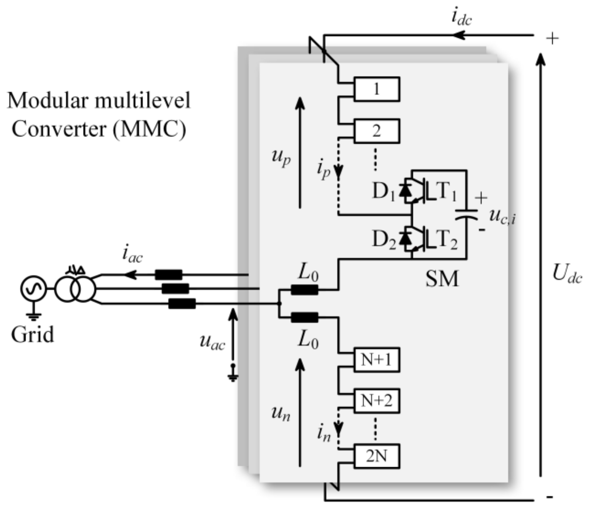
Figure 1. The topology structure of the three-phase MMC.
Energies 17 00061 g001
Figure 2. The proposed voltage sensorless estimation method for the MMC.
Energies 17 00061 g002
Figure 3. An 8 kVA down-scale MMC experimental prototype.
Energies 17 00061 g003
Figure 4. Measured and estimated ac-side voltages and the error between them under inductance mismatches: (a) L / L 0 = 1 ; (b) L / L 0 = 0.5 ; (c) L / L 0 = 1.5 .
Energies 17 00061 g004
Figure 5. Fundamental component and THD of the ac-side voltage between the original method without DOB and the proposed method with DOB: (a) L / L 0 = 1 ; (b) L / L 0 = 0.5 ; (c) L / L 0 = 1.5 .
Energies 17 00061 g005
Figure 6. Measured and estimated dc bus voltages and the error between them.
Energies 17 00061 g006
Figure 7. Estimated SM capacitor voltages under steady-state condition. (a) Estimated SM capacitor voltages in the upper and lower arms. (b) Measured and estimated 1st SM capacitor voltages and the error between them.
Energies 17 00061 g007
Figure 8. Estimated SM capacitor voltages under dynamic conditions.
Energies 17 00061 g008
Figure 9. Measured and estimated ac-side voltages: (a) L / L 0 = 1 ; (b) L / L 0 = 0.5 ; (c) L / L 0 = 1.5 .
Energies 17 00061 g009
Figure 10. Measured and estimated dc bus voltages.
Energies 17 00061 g010
Figure 11. Estimated SM capacitor voltages in the upper and lower arms under steady-state conditions. (a) Estimated SM capacitor voltages in the upper arm. (b) Estimated SM capacitor voltages in the lower arm.
Energies 17 00061 g011
Figure 12. Estimated and measured 1st SM capacitor voltages under dynamic conditions.
Energies 17 00061 g012
Table 1. Design parameters of the system.
ParameterSimulationExperiment
Nominal power1.2 MVA8 kVA
The ac-side current peak100 A20 A
The dc bus voltage20 kV600 V
Arm inductance20 mH8 mH
Line frequency50 Hz50 Hz
Number of SMs per arm104
SM capacitance2000 μF1640 μF
SM capacitor voltage2000 V150 V
Sampling and control period20 μs50 μs
Table 2. Fundamental component and THD of ac-side current in the experiment.
Inductance MismatchFundamental Component (A)THD (%)
without DOBwith DOBwithout DOBwith DOB
L / L 0 = 1 19.608719.59325.095.45
L / L 0 = 0.5 19.513919.52006.796.06
L / L 0 = 1.5 19.670119.67084.725.38
Disclaimer/Publisher’s Note: The statements, opinions and data contained in all publications are solely those of the individual author(s) and contributor(s) and not of MDPI and/or the editor(s). MDPI and/or the editor(s) disclaim responsibility for any injury to people or property resulting from any ideas, methods, instructions or products referred to in the content.