1. Introduction
As an unconventional natural gas resource, coalbed methane (CBM) is an important clean energy source to improve the primary energy consumption structure in China. However, it is also an important greenhouse gas with a greenhouse effect of 21 times that of carbon dioxide; accelerating the development and utilisation of CBM can increase the supply of clean energy, turning harm into benefit and waste into treasure [
1]. Among the existing CBM production increase measures, horizontal well slit and multi-cluster perforation fracturing are widely used with the advantages of being able to form a complex fracture network and large pressure relief area [
2]. However, scholars at home and abroad have found through monitoring such as DTS (distributed fibre optic temperature test), DAS (distributed noise test) or microseismic that about 20% of perforations contribute 80% of the production after fracturing [
3]. About 20~40% of the fractured perforations do not contribute to the production capacity, which are ineffective perforations [
4,
5,
6,
7]. The unbalanced production distribution of fracturing perforations indicates that serious fracture unbalanced extension phenomenon occurs in intra-cluster fracturing [
8,
9], and the phenomenon of unbalanced extension of multi-fractures seriously restricts the production increase effect of segmented multi-cluster fracturing in horizontal wells and its negative impacts mainly have two points. Firstly, in the uneven development of multi-fracture, the reservoir failed to obtain the maximum degree of transformation, and the failure of fracturing injection in some clusters caused cost waste. Secondly, as individual dominant fractures acquire the majority of fracturing fluids, there is a risk of their development being out of control, and excessively long fractures may communicate with adjacent fractured wells, forming serious inter-well interference and leading to production reductions in neighbouring wells [
10,
11,
12,
13,
14,
15,
16,
17,
18].
In addition, horizontal well slit and multi-cluster perforation fracturing technologies can also be used in the following areas: (1) Oil and gas extraction: It can improve the production capacity of oil and gas wells and increase the amount of oil and gas extraction. The permeability can be significantly improved, especially for low-permeability oil and gas formations, and the extraction efficiency can be increased. (2) Geothermal energy development: It can also be applied in geothermal energy development. By injecting high-pressure water underground, the cracks can be enlarged to improve the permeability of geothermal wells and increase the amount of geothermal energy harvested; (3) Storage reservoir increase: It can also be applied to the construction of storage facilities such as reservoirs and gas storage tanks. By enlarging the rock cracks, the storage capacity of the storage facility can be increased, and the storage efficiency can be improved.
At present, horizontal well segmental fracturing mainly adopts the intensive cut-and-separate fracturing technique with three clusters, a single section length of 50–55 m and cluster spacing of 6–15 m [
19]; however, when multi-fracture initiation and expansion are carried out in clusters, the central perforation is interfered by the stress shadows, and the fractured fracture expansion is inhibited [
20]. In order to investigate the simultaneous fracture initiation and expansion law of multi-fracture, scholars have carried out in-depth research in recent decades.
In the numerical simulation, Peirce et al. [
21] showed that the inner seamstress interference is the main reason affecting the balanced extension of multi-fracture and pointed out that non-equilibrium perforation cluster arrangement can effectively attenuate the effect of stress shadowing. Bunger et al. [
22] found that the existing hydraulic fracturing cracks will lead to the deviation of the crack paths of the subsequent fracturing cracks, and the smaller the cluster spacing is, the more serious the phenomenon of the deviation is. Lecampion et al. [
23], based on the established numerical model of multi-fracture expansion, investigated the influence law of different perforation cluster parameters and non-equilibrium perforations on the fluid injection volume and fracture expansion morphology in the fracture and pointed out that the perforation ordinance can alleviate the stress interference between clusters. The optimisation of the number of perforations can improve the effect of simultaneous initiation and expansion of multiple clusters. Wu et al. [
24] pointed out that the internal fracture in the action of the stress shadow increased additional flow resistance. The amount of fluid injection in the internal cracks was reduced, which led to the unevenness of internal crack expansion and limited the formation of volumetric cracks. However, the expansion pattern of the internal cracks could be significantly improved by decreasing the diameter of the external perforations or increasing the spacing of the perforations. For indoor experiments, Liu et al. [
25] revealed the effects of segment spacing, perforation parameters, horizontal stress difference and cementing quality of horizontal well sections on the expansion pattern of multiple fractures. They pointed out that larger segment spacing makes the subsequent fractures in the region of induced stress decrease, which reduces the degree of stress interference and promotes balanced fracture expansion. Professor Xia et al. [
3] found that the induced stress field is challenging to change the magnitude of the original principal stress under the condition of high-stress difference. The fracture is more likely to form a transverse slit parallel to the direction of the maximum principal stress. In contrast, the use of large displacement fracturing makes the net water pressure inside the fracture increase, and the angle and degree of multi-fracture deflection increase, which makes the formation of a longitudinal slit more likely. Zhou et al. [
26] showed that due to a pore pressure field, intra-cluster and inter-cluster fractures show mutual attraction between fractures when the ratio of fracture spacing to fracture half-length is small. At present, although the research on the simultaneous initiation and expansion of multiple cracks has achieved specific results, the relevant research is still in the initial stage and still needs improvement. On the one hand, most of the existing research adopts numerical simulation methods, and there is a lack of the most direct physical experiments to verify the synchronous crack initiation and expansion law of multi-fracture under the effect of stress shadowing; on the other hand, the research on the simultaneous initiation and expansion of multi-fractures under the effect of stress shadowing is limited to the research on the change rule of the overall initiation pressure of the specimen and the research on the evolution rule of the fluid injection flow and pressure in the fracturing injection holes is missing, which is extremely important for the study to reveal the control mechanism of the transformation of multi-fractures from the “uneven” to the “balanced” expansion.
To this end, this paper makes use of the self-developed “TCHFSM-I” large-size accurate triaxial fracturing seepage simulation device and fluid injection flow dynamic monitoring device to study the crack initiation and expansion law of multi-fracture under different perforation spacing conditions and based on the evolution law of the injection pressure and the characteristics of the distribution of the injection flow rate, it reveals the mechanism of the multi- fracture’s expansion from non-equilibrium to equilibrium.
2. Test Introduction
2.1. Test Equipment
2.1.1. Hydraulic Fracturing Test Device
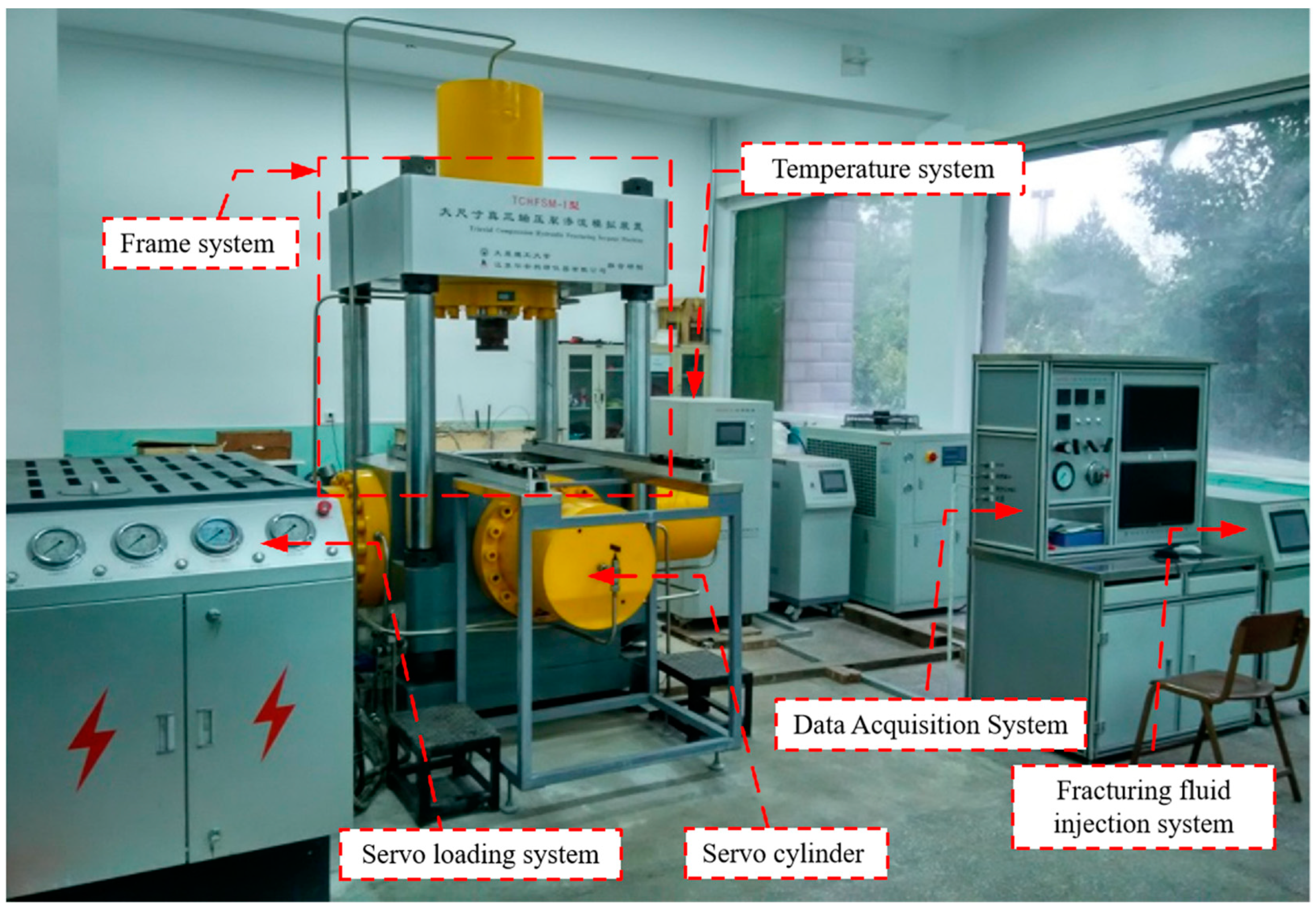
The hydraulic fracturing test adopts the self-developed TCHFSM-I large-size true triaxial fracturing seepage simulation device [
1], which consists of three parts: triaxial pressurisation control system, fracturing medium injection system and information collection system. The fracturing medium injection system consists of a constant pressure pump and an air quiet pump, and the fracturing fluid is injected into the specimen through the high-pressure pump to achieve hydraulic fracturing; the information collection system consists of pressure sensors and a centralised control and monitoring station, and the injection pressure is collected in real-time by three pressure sensors at a frequency of 10 times/s. The real-time data of the injection pressure are collected and observed through the centralised control and monitoring station, and the test setup is shown in
Figure 1. The test device is shown in
Figure 1. The maximum loading force of the test device is 3000 kN, the maximum size of the specimen is 400 mm cube specimen, and the liquid injection rate can reach 200 mL/min, which meets the requirements of this test.
Standard cylindrical specimens were cast with cement mortar, and their mechanical parameters were determined; three groups are shown in
Table 1 below.
In addition, all experiments were conducted at room temperature, and the fluids used in the tests had the same chemical composition.
2.1.2. Acoustic Emission System
The acoustic emission system adopts the SAEU3H-1016-08 monitoring device (SAEU3H digital acoustic emission meter based on a Windows system. It adopts a US3.0 communication structure consisting of four main parts: transducer, preamplifier, host computer and computer installed with acquisition and analysis software), which can dynamically monitor the internal damage of the specimen in real-time during the fracturing experiment. In order to more accurately determine the crack extension path of hydraulic fracturing, a total of eight acoustic emission probes were deployed in the test to achieve accurate positioning, as shown in
Figure 2. In addition, in order to avoid the interference of external factors on the acoustic emission monitoring, the acoustic emission probes are directly buried in the specimen. The holes with a diameter of 22 mm and a depth of 25 mm are first drilled at the eight vertices of the specimen. Then, a certain amount of petroleum jelly is applied at the bottom of the drilled holes in order to prevent the acoustic emission probes from not being securely fitted with the drilled holes. Then, finally, they are sealed by gypsum.
2.1.3. Liquid Injection Flow Measurement System
As the hydraulic fracturing test in this paper adopts synchronous fracturing with multiple perforations, in order to monitor the fluid flow in each perforation, the fluid flow in each fractured perforation is monitored in real-time by the high temperature–high-pressure shallow flow dynamic monitoring system, which has a monitoring range of 0~50 mL/min and a monitoring accuracy of 0.1 mL/min and can accurately measure the dynamic evolution of the fluid flow over time. The high-temperature–high-pressure very-low-flow dynamic monitoring system device is shown in
Figure 3.
2.2. Specimen Preparation
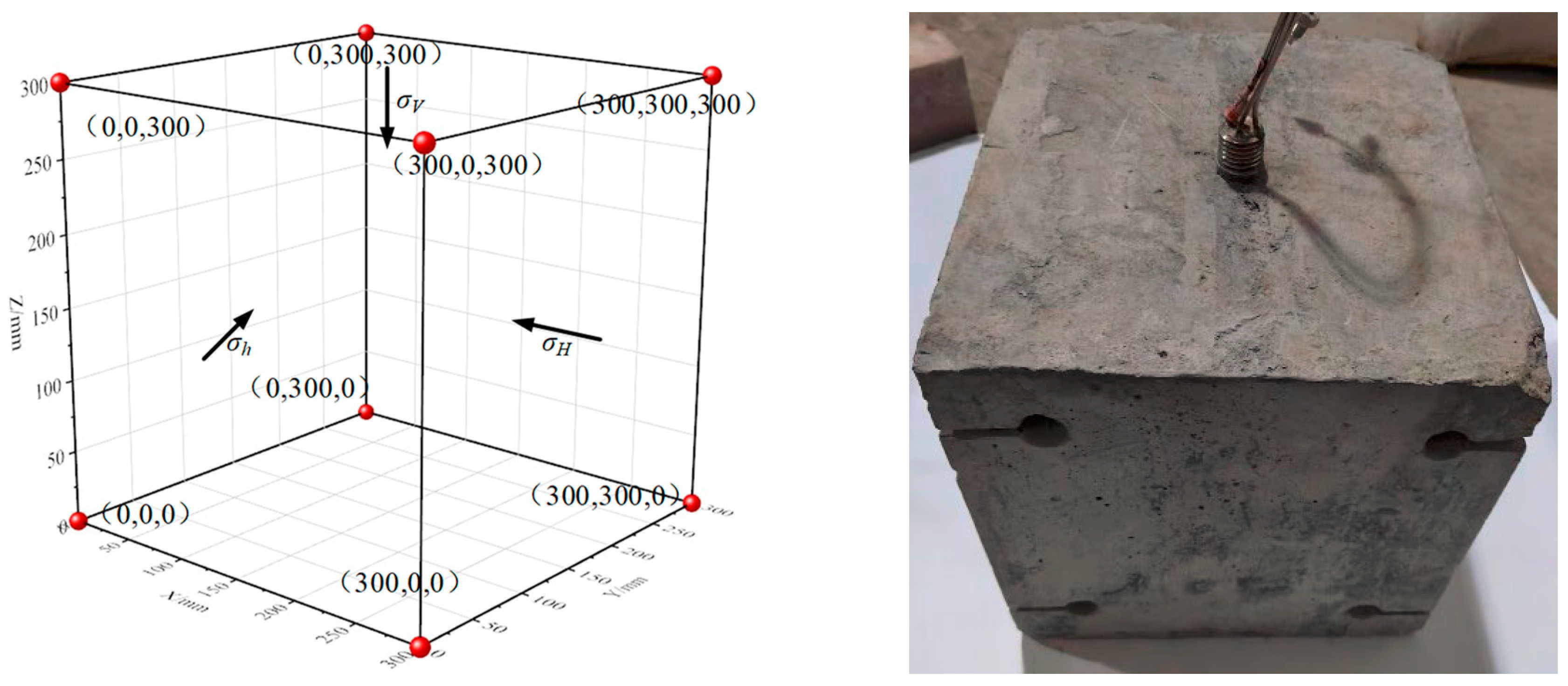
The test adopts manually prefabricated 300 mm × 300 mm × 300 mm cubic concrete specimens as the research object. Then, it reveals the simultaneous expansion law of multi-cracks under the condition of different perforation spacing. The process of concrete specimen preparation is as follows:
- (1)
Apply lubricant inside the 300 mm × 300 mm × 300 mm cube mould, and then place the fractured wellbore (perforation spacing 10~80 mm) in the central position of the mould;
- (2)
Place the well-mixed cement mortar (cement: fine sand: water = 2:2:1, of which, the cement type is P.II42.5 silicate cement) inside the mould, add defoamer and vibrate fully with the vibrating rod during the pouring process, and then complete the specimen pouring work;
- (3)
Remove the concrete paste specimen from the mould at the beginning of setting, place it in the curing box, standard curing for 28 d;
- (4)
Grind the surface of the cured concrete specimen to make the surface of the specimen smooth to ensure the uniformity of the force on all surfaces in the hydraulic fracture test;
- (5)
Drill the acoustic emission probe monitoring holes on the surface of the specimens with a drilling machine and set up the acoustic emission monitoring probes;
- (6)
Mark the specimens according to the experimental design scheme and set them aside.
The schematic diagram of the prepared specimen (with the perforation spacing of 50 mm, for example) is shown in
Figure 4a, and the physical drawing is shown in
Figure 4b.
In addition, to ensure as much homogeneity as possible in the test-prepared specimens and reduce the variability between samples. A total of 15 pairs of monitoring points are arranged on the six independent surfaces of the prepared cube, ultrasonic longitudinal wave detection is carried out at the monitoring points, specimens with large dispersion values of longitudinal wave velocity are rejected, and the remaining specimens are tested commonly.
2.3. Test Plan and Process
2.3.1. Test Scheme
In this test, the effect of perforation spacing from 10 to 80 mm on the simultaneous initiation and expansion of hydraulic fracturing cracks was considered, and the test programme consisted of a total of eight groups, with three specimens repeating for each group of experimental conditions, and the hydraulic fracturing test programme is shown in
Table 2.
2.3.2. Experimental Procedure
- (1)
The specimen was first wrapped with a rubber sleeve and placed in the fracturing chamber as a whole, after which five servo-controlled cylinders preloaded the specimen;
- (2)
After the preloading, the specimen was subjected to synchronous gradient loading, in which the triaxial stress was loaded synchronously to the set value of σv, then σh and σH were loaded synchronously to the minimum horizontal principal stress of σh to the set value, and finally the maximum horizontal principal stress of σH was loaded to the set value, and the pressure was stabilised for 10 min;
- (3)
Connecting the fracturing medium injection system, the information collection system and the acoustic emission monitoring system, and then synchronously turning on the above monitoring system so as to accurately monitor the injection pressure, the dynamic response characteristics of acoustic emission and the evolution characteristics of the injection flow rate;
- (4)
After the test is turned on, pay attention to the fluid injection pressure, fluid flow rate and acoustic emission monitoring system at all times, observe the fracturing condition of the specimen synchronously, and then stop the test systems synchronously when the specimen surface has apparent water emergence phenomenon;
- (5)
Unload the triaxial stress to 0 kN in a synchronous gradient, then remove the specimen from the loading platform, observe the crack extension and take photos.
3. Results and Analysis
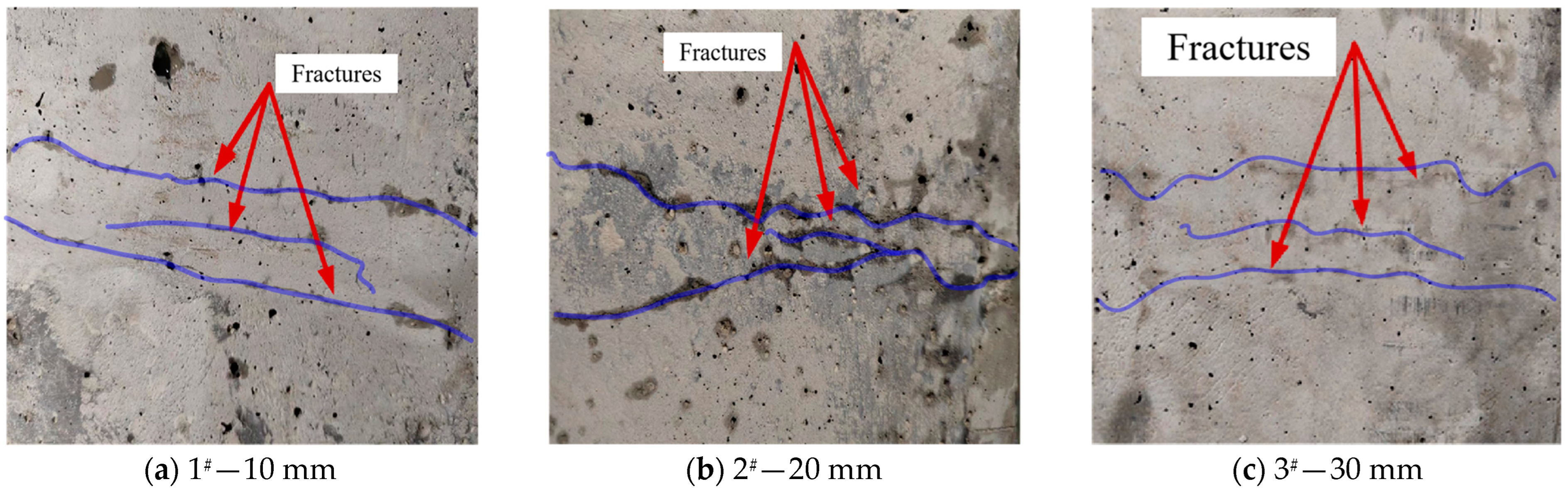
This paper first analyses the simultaneous expansion law of hydraulic fracturing by observing the fracture morphology of hydraulic fracturing specimens. It then analyses and verifies it through the evolution law of fluid injection pressure, dynamic response characteristics of acoustic emission, and the evolution characteristics of fluid injection flow rate. One specimen is selected from each group for analysis, and the fracture expansion patterns of the specimens after fracturing with different perforation spacings are shown in
Figure 5.
3.1. Analysis of Multi-Crack Propagation Length under Different Perforation Spacing
As can be seen from
Figure 5, in general, three obvious hydraulic fracturing cracks were formed on the specimen surface by multi-perforation fracturing, which had no apparent relationship with the size of the perforation spacing. However, with the different perforation spacing, the extended length of the hydraulic fracturing cracks produced by the upper, middle and lower perforations was different. Especially when the perforation spacing is small, the middle perforation hydraulic fracturing cracks are affected by the upper and lower perforation hydraulic fracturing cracks in the expansion process, and the expansion length of the middle cracks is shorter. In order to analyse the influence of the spacing of the perforations on the synchronous expansion of the upper, middle and lower hydraulic fracturing cracks, this paper adopts the expansion length of hydraulic fracturing cracks for statistical analysis, and the statistical results are shown in
Figure 6.
As can be seen from
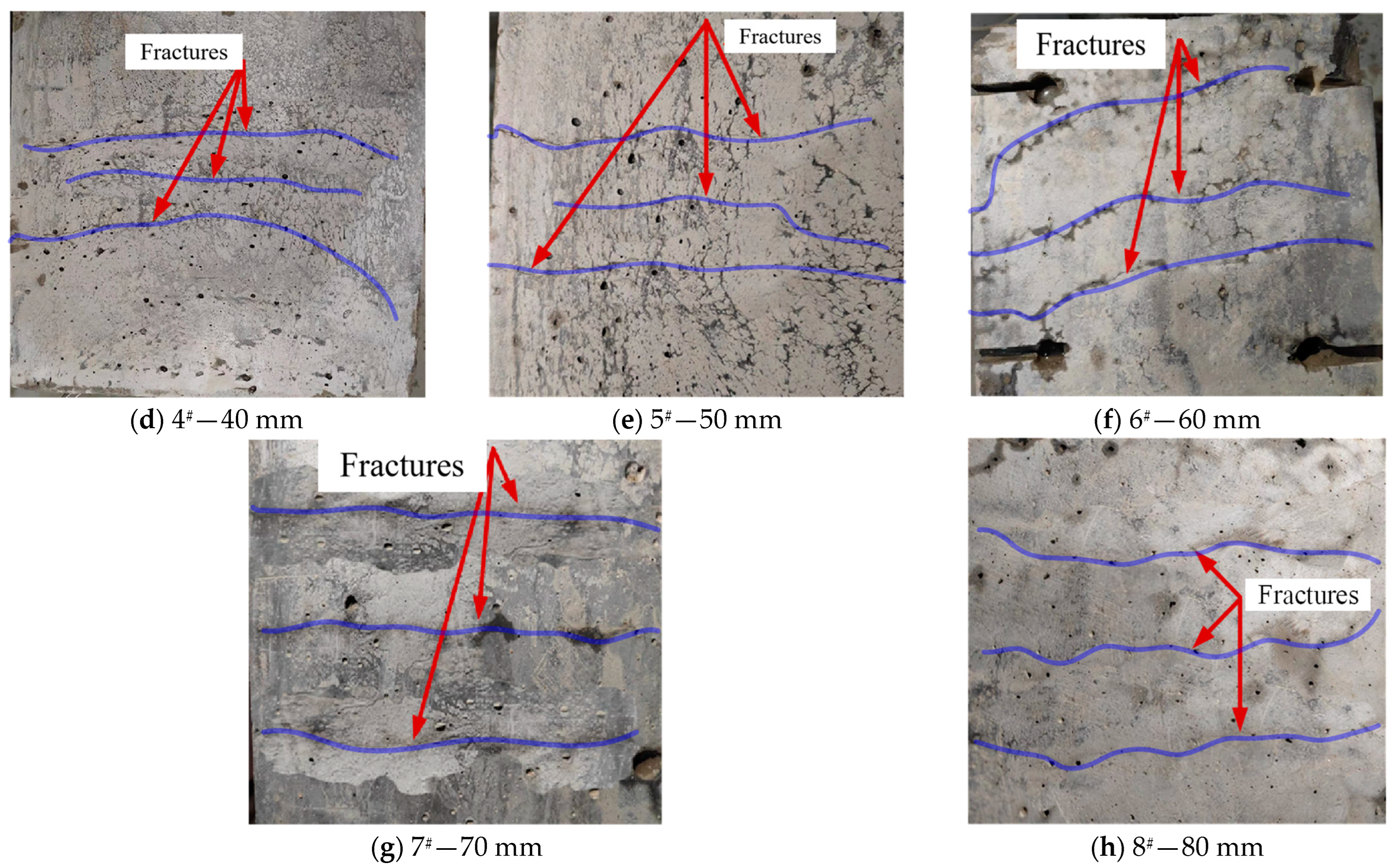
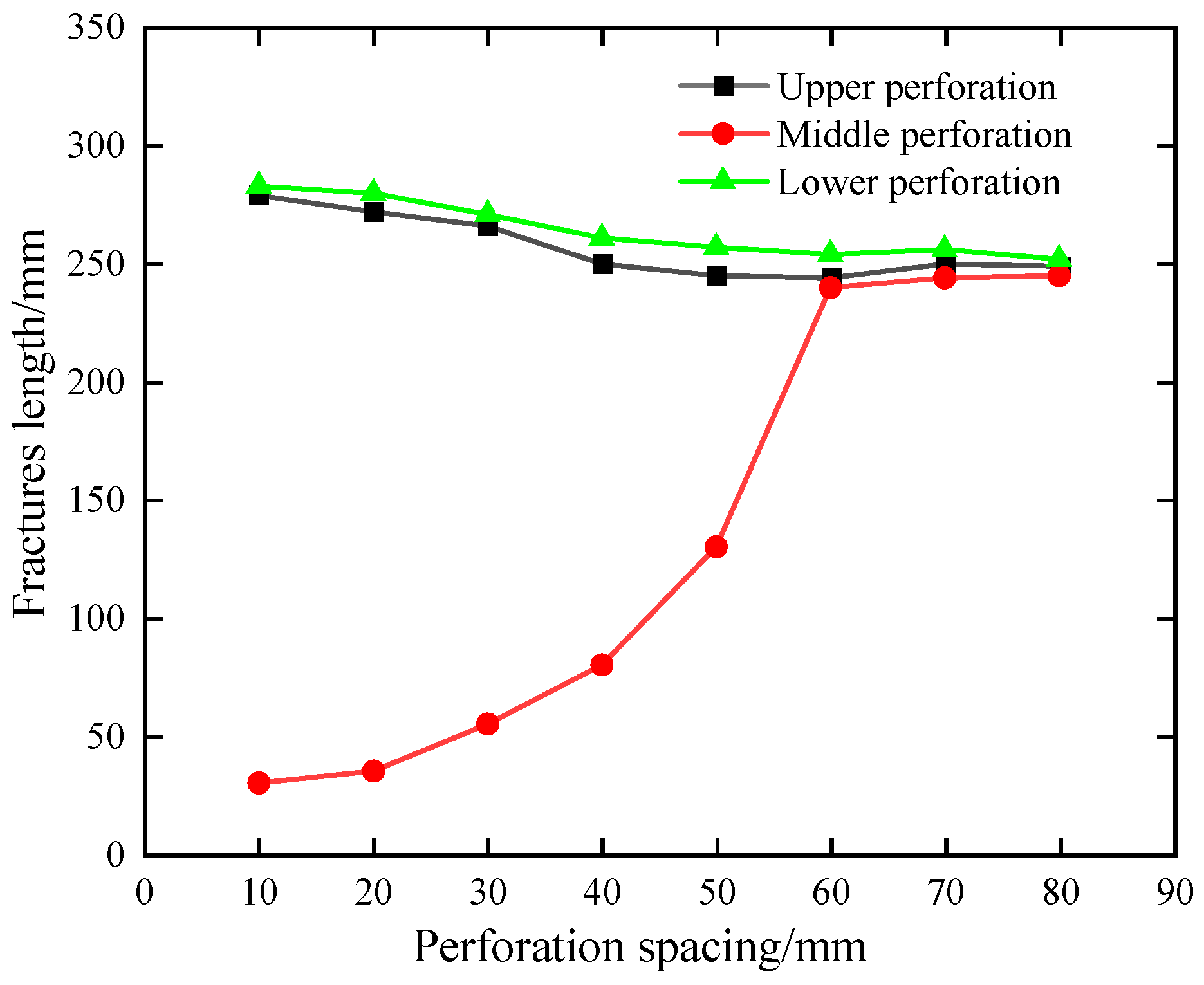
Figure 6, when the perforation spacing is small (<60 mm), the hydraulic fracturing crack extension lengths of the upper and lower sides are the same, and significantly more extensive than that of the central perforation hydraulic fracturing cracks. For example, when the perforation spacing is 10 mm, 20 mm, 30 mm, 40 mm and 50 mm, the lengths of the upper perforation cracks are 279 mm, 272 mm, 266 mm, 250 mm and 245 mm, the lengths of the lower perforation cracks are 283 mm, 280 mm, 271 mm, 61 mm and 257 mm, and the lengths of the middle perforation cracks are 30 mm, 35 mm, 55 mm, 80 mm and 130 mm.
When the perforation spacing gradually increases (≥60 mm), the extension lengths of the upper, middle and lower hydraulic fracturing cracks do not differ much, and it can be seen that the extension lengths of the middle hydraulic fracturing cracks gradually increase with the increase in the perforation spacing. For example, when the perforation spacing is 60 mm, 70 mm and 80 mm, the upper perforation crack lengths are 244 mm, 250 mm and 249 mm, and the middle perforation crack lengths are 240 mm, 244 mm and 245 mm and the lower perforation crack lengths are 254 mm, 256 mm and 252 mm.
In general, due to the different perforation spacing, there are significant differences in the extension patterns of the upper, central and lower hydraulic fracturing cracks. When the perforation spacing is 10~50 mm, the central perforation crack is affected by the expansion of the upper and lower perforation cracks, and its extension length is shorter, which indicates that due to the smaller perforation spacing, the central perforation crack is affected by the local stress field of the two-perforations, which produces the inter-seam stress interference effect, i.e., the so-called stress shadow effect. When the perforation spacing is 60–80 mm, the extension lengths of the upper, middle and lower perforation cracks are the same, which indicates that the stress shadow effect disappears with the increase in perforation spacing. The three hydraulic fracturing cracks shift from the unbalanced extension of the shorter perforations to the balanced extension.
3.2. Evolution Law of Fluid Pressure under Different Perforation Spacing Conditions
The above study shows that the simultaneous expansion law of hydraulic fracturing cracks under different perforation spacing varies significantly. Due to the different crack expansion laws, the evolution law of fluid injection pressure in each perforation tends to differ, which can further invert the differences in hydraulic fracture expansion and reveal its inner mechanism. The fluid injection pressure evolution law under different perforation spacings is shown in
Figure 7.
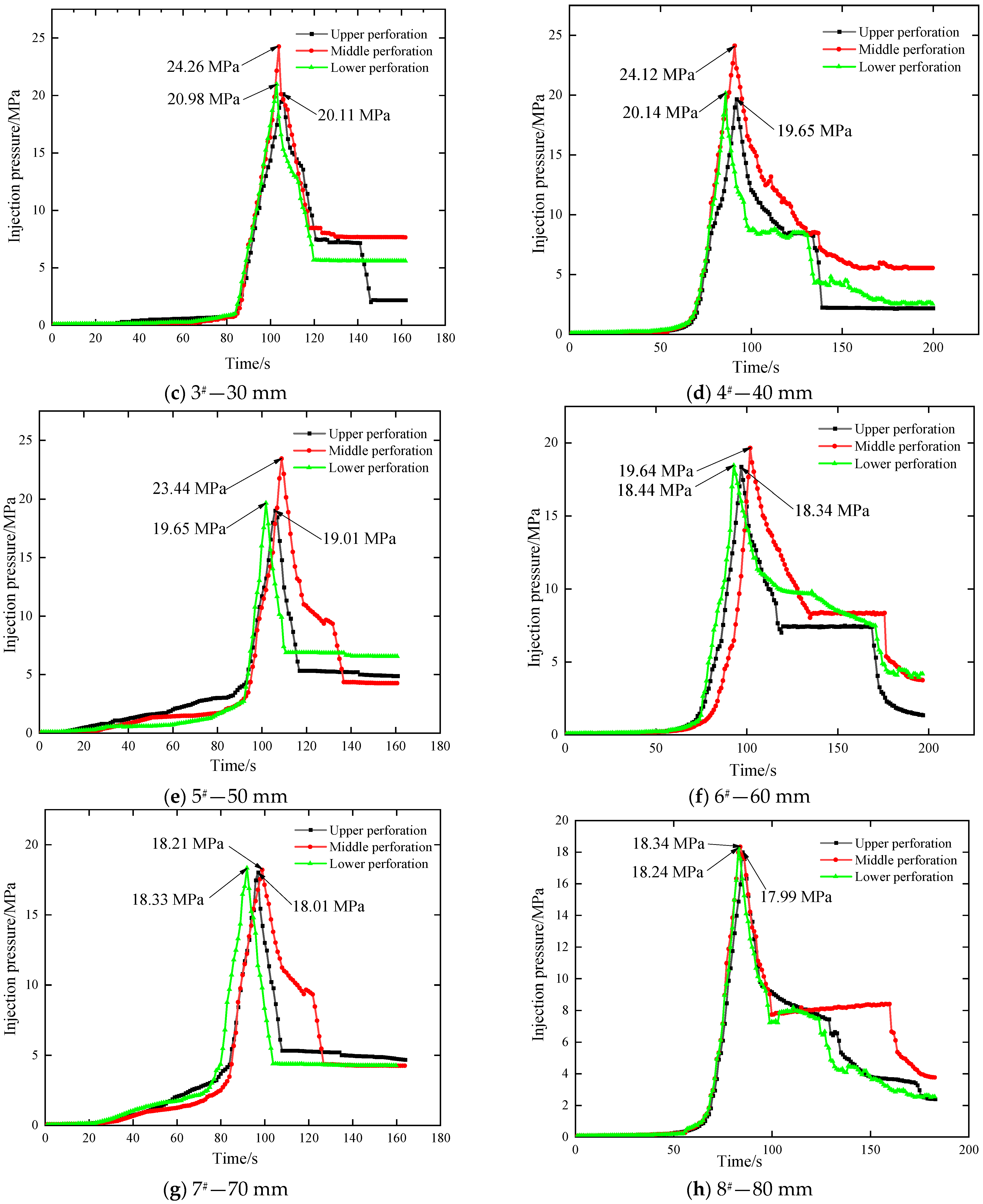
From
Figure 7, it can be seen that due to the different perforation spacing, the injection hydraulic cracking pressure of the perforations in each specimen is significantly different, but the general law is basically the same, i.e., the evolution law of the injection pressure can be divided into three stages as a whole. Stage I: pressure-holding stage, at which the pressure rises steadily; Stage II: rapid fracture expansion stage, at which the pressure decreases rapidly from the peak; Stage III: pump injection filtration out-of-equilibrium stage, at which the pressure is maintained at a low level and fracturing is completed, i.e., a penetrating hydraulically fractured fracture is formed.
In order to further investigate the influence of perforation spacing on the evolution of injection pressure, this section focuses on the differences in fracture initiation pressures of the upper, middle and lower fracturing perforations (shown in
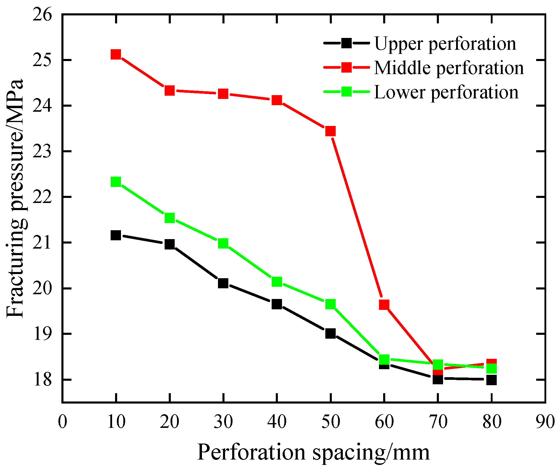
Figure 8) and then reveals the mechanism of its action. Comparing the fracture initiation pressures of the upper, middle and lower perforations under different perforation spacing conditions, it can be seen that the fracture initiation pressures of the upper and lower perforation hydraulic fracturing fracture are the same when the perforation spacing is small (10–50 mm) but much lower than that of the middle perforation fracturing fracture initiation pressure. For example, when the perforation spacing is 10 mm, the fracture initiation pressures of the upper, middle and lower perforations are 21.16 MPa, 25.12 MPa and 22.33 MPa, respectively, which can be seen that the fracture initiation pressures of the upper and lower perforations are the same. However, there is a significant difference between them and the middle perforations, with the fracture initiation pressures of the middle perforations increasing by as much as 19% and 12.5% compared to those of the upper and lower perforations. When the perforation spacing increases to 60 mm and above, the fracturing pressure of the upper, middle and lower perforations is 18.34 MPa, 19.64 MPa and 18.44 MPa, respectively, which can be seen that the fracturing pressures of the three fracturing perforations are the same as the perforation spacing increases, which has significant differences with the lower perforation spacing. It can be seen that the inter-seam interference effect decreases or even disappears when the perforation spacing is more significant. The fracture initiation pressure of the upper, middle and lower three perforations is the same, the extension pressure of the fracture after fracture initiation is smoother, which indicates that the three-fracture initiation and extension have little influence on each other and the inter-seam interference becomes smaller.
In order to further investigate the influence of perforation spacing on the evolution of injection pressure, this section focuses on the differences in fracture initiation pressures of the upper, middle and lower fracturing perforations (shown in
Figure 8) and then reveals the mechanism of its action. Comparing the fracture initiation pressures of the upper, middle and lower perforations under different perforation spacing conditions, it can be seen that the fracture initiation pressures of the upper and lower perforation hydraulic fracturing fracture are the same when the perforation spacing is small (10–50 mm) but much lower than that of the middle perforation fracturing fracture initiation pressure. For example, when the perforation spacing is 10 mm, the fracture initiation pressures of the upper, middle and lower perforations are 21.16 MPa, 25.12 MPa and 22.33 MPa, respectively, which can be seen that the fracture initiation pressures of the upper and lower perforations are the same. However, there is a significant difference between them and the middle perforations, with the fracture initiation pressures of the middle perforations increasing by as much as 19% and 12.5% compared to those of the upper and lower perforations. When the perforation spacing increases to 60 mm and above, the fracturing pressure of the upper, middle and lower perforations is 18.34 MPa, 19.64 MPa and 18.44 MPa, respectively, which can be seen that the fracturing pressures of the three fracturing perforations are the same as the perforation spacing increases, which has significant differences with the comparatively small perforation spacing. It can be seen that the inter-seam interference effect decreases or even disappears when the perforation spacing is more significant. The fracture initiation pressure of the upper, middle and sommelier three perforations is the same; the extension pressure of the fracture after fracture initiation is smoother, which indicates that the three-fracture initiation and extension have little influence on each other, and the inter-seam interference becomes smaller.
In summary, when the perforation spacing is small, the upper, middle and lower perforation injection pressure evolution laws are significantly different. Its inner seam cracking interferes strongly, considerable middle perforation crack initiation pressure and crack initiation difficulties, and the middle perforation crack initiation pressure is larger than the upper and lower sides of the hydraulic fracture crack initiation pressure; with the increase in perforation spacing, the upper, middle and lower perforation hydraulic fracture crack initiation pressure is reduced, which indicates that increasing the perforation spacing can reduce the inter-seam crack initiation interference, making the fracture easier, and the upper, middle and lower perforation hydraulic fracture crack initiation pressure is the same, which indicates that the fracture initiation pressure of the three injection cracks is independent of each other. The extension pressure of the subsequent cracks is flat, which indicates that there is little interference between the cracks, and the stress shadowing effect decreases and disappears gradually.
4. Discussion and Analysis
Based on the above analyses, it can be seen that there are significant differences between the crack initiation and expansion patterns of hydraulic fracturing cracks and the fluid injection pressure evolution patterns under different perforation spacing conditions, which are mainly attributed to the interstitial stress shadowing effect. However, the mechanism of the stress shadowing effect on the crack expansion or the fluid injection pressure still needs to be clarified. In order to further explore the mechanism of the stress shadow effect, this section discusses and analyses the night injection flow rate in the upper, middle and lower perforations and then reveals the multi-fracture extension pattern of hydraulic fracturing.
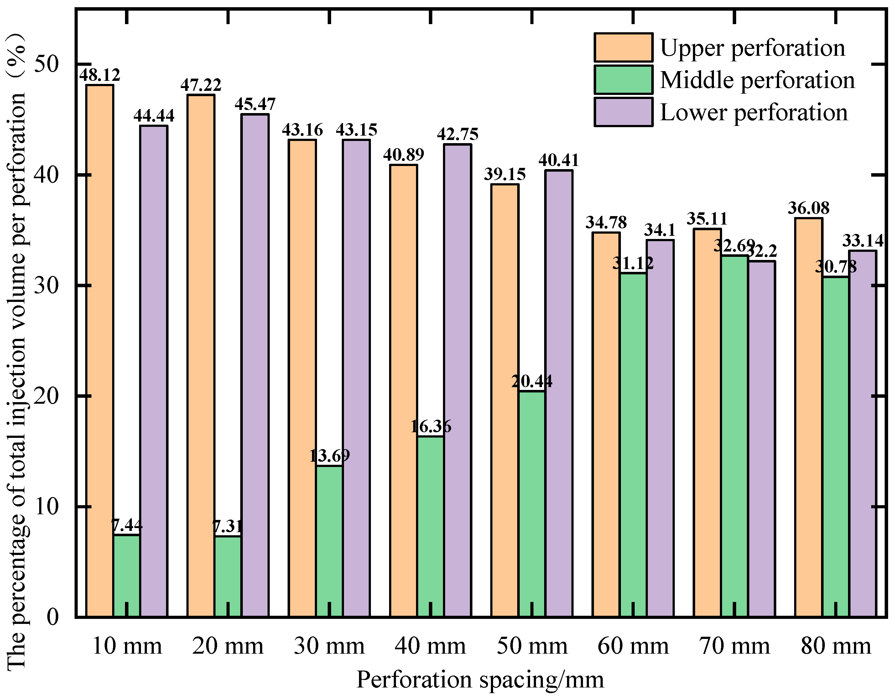
Figure 9 shows the percentage of fluid injection flow in the upper, middle and lower perforations of specimens with different perforation spacing to the total flow rate.
When the perforation spacing is small (10~50 mm), the upper and middle perforation injection flow rate is the same as the total injection flow rate. However, both are much larger than the central perforation injection flow rate. For example, when the perforation spacing of 10 mm, 20 mm, 30 mm, 40 mm and 50 mm, the upper perforation injection flow accounted for the total injection flow of 48.12%, 47.22%, 43.16%, 40.89% and 39.15%, the lower perforation injection flow accounted for the total injection flow accounted for 44.44%, 45.47% and 43.15%, respectively, 42.75%, 40.41%, and the ratio of the injection flow rate of the middle perforation to the total injection flow rate is 7.44%, 7.31%, 13.69%, 16.36% and 20.44%, respectively. It can be seen that when the perforation spacing is less than 60 mm, the upper and lower injection flow rates are higher. Hence, the upper and lower injection crack extension length is more significant. In contrast, under stress shadowing, the central injection flow rate is less than 10%, which leads to a shorter extension length of the central injection crack and the injection pressure.
When the perforation spacing was increased to 60 mm, 70 mm and 80 mm, the upper perforation injection flow rate was 34.78%, 35.11% and 36.08% of the total injection flow rate, the lower perforation injection flow rate was 34.1%, 32.2% and 33.14% of the total injection flow rate, and the middle perforation injection flow rate was 31.12% of the total injection flow rate, respectively, 32.69% and 30.78%, respectively. It can be seen that, with the increase in the perforation spacing, the proportion of the injection flow rate in the upper and lower perforations gradually decreases, and the proportion of the injection flow rate in the middle perforations gradually increases. Finally, the proportion of the injection flow rate in the three perforations reaches equilibrium and tends to be the same. For example, when the perforation spacing increases from 10 mm to 80 mm, the upper perforation injection flow rate percentage decreases from 48.12% to 34.78%, a decrease of 13.34%, the lower perforation injection flow rate percentage decreases from 44.44% to 33.14%, a decrease of 11.3%, and the central perforation injection flow rate percentage increases from 7.44% to 30.78%, an increase of 23.34%. Currently, the extension lengths of the upper, middle and lower hydraulic fracturing cracks are the same. The hydraulic fracturing crack initiation pressures in the three perforations are the same, which suggests that the inner seamstress shadowing effect of the hydraulic fracturing cracks is gradually weakened with the increase in the perforation spacing, which in turn prompts the fracture extension of the three perforations to change to the balanced extension from the uneven extension gradually.
Generally speaking, when the spacing of perforations is small, during the crack initiation and expansion process of multi-fracture, the stress shadow effect interferes more with the crack initiation and expansion of the hydraulic fracturing cracks in the middle perforation. At this time, the middle crack needs a more considerable fluid pressure to balance the stress interference carried by the expansion of the outer hydraulic fracture cracks, which leads to the restriction of the expansion of the fracturing cracks in the middle perforation and the allocated injection flow rate is extremely low, resulting in an uneven distribution of injection flow rate of the three perforations, which leads to the failure of balanced expansion of multi-fractures. When the spacing of perforations is larger, the inter-seam stress interference is weakened or even disappeared during the simultaneous expansion of multiple fractures, and the fluid injection flow of the upper, middle and lower perforations is uniformly distributed, which leads to the balanced expansion of multiple fractures from sub-balanced expansion to balanced expansion. It can be seen that, in order to increase the volume of reservoir reforming and enhance the effect of hydraulic fracturing to increase production to a more significant extent, the spacing of perforations should be increased appropriately to reduce the influence of the stress shadow effect on the synchronous expansion of multi-fractures, to promote the balanced expansion of multi-fractures.
5. Conclusions
In this paper, based on 300 × 300 × 300 mm cement mortar specimens, we investigated the crack initiation and expansion law of multi-cracks under different perforation spacing conditions through hydraulic fracturing tests. At the same time, based on the injection pressure monitoring system and the self-developed injection flow rate monitoring system, we investigated the evolution law of the injection pressure and the relationship between injection flow rate during the crack initiation and expansion process. Then, the mechanism of the inner seamstress shadowing on multi-fracture expansion from unbalanced to balanced expansion was revealed. The main conclusions are as follows:
- (1)
The perforation spacing significantly affects the synchronous fracture extension pattern of multi-fractured cracks. When the perforation spacing is small (<60 mm), the central perforation fractured cracks are affected by the expansion of the upper and lower perforation cracks, and their extension lengths are shorter, with a significant inter-seam stress shadow effect; when the perforation spacing (≥60 mm) is larger, the extension lengths of the upper, central and lower perforation cracks are the same, which means that with the increase in the perforation spacing, the stress shadow effect is weakened or even disappeared. The three hydraulic fracturing fractures changed from the unbalanced expansion during short perforation to the balanced expansion.
- (2)
The evolution characteristics of multi-fracture injection pressure under different perforation spacing conditions differ significantly. When the perforation spacing is small, the crack initiation pressure of the central perforation is enormous. The crack initiation is complex, and its crack initiation pressure is much larger than the upper and lower hydraulic crack initiation pressure. With the increase in perforation spacing, the fracture initiation pressure of the central perforation gradually decreases. Its fracture initiation pressure is the same as the fracture initiation pressure of the upper and lower perforations. The expansion of the three hydraulic fractured cracks is independent of each other, which indicates that the stress shadow effect is weakened by the increase in perforation spacing, which leads to a decrease in the fracture initiation pressure.
- (3)
The evolution of the injection flow rate can better respond to the multi-fracture initiation and expansion pattern. When the perforation spacing is small, the proportion of the total injection flow in the upper and middle perforations is the same, but the two are much larger than that in the middle perforation; when the perforation spacing increases, the proportion of the injection flow in the upper and lower perforations decreases, the proportion of the injection flow in the middle perforations increases, and the proportion of the injection flow in the last three perforations reaches the equilibrium and tends to be the same. This shows that with the increase in perforation spacing, the interstitial stress shadow effect of hydraulic fracturing cracks is gradually weakened, which drives the crack expansion of the three perforations from unbalanced to balanced expansion.
6. Research Perspectives
This paper mainly investigates the fracture initiation and expansion law of multi-fractures under different perforation spacing conditions based on artificial cement mortar specimens. It reveals the mechanism of multi-fracture expansion from unbalanced to balanced based on the evolution law of injection pressure and the injection flow rate distribution characteristics. When facing the actual working conditions, the perforation spacing should be increased appropriately according to the field conditions. This can effectively weaken the stress shadow effect, promote the balanced expansion of fractured cracks, and increase the coalbed methane production. It is of great practical significance for the efficient development of CBM resources and for reducing the cost of deep CBM extraction.
Due to the author’s lack of knowledge and ability, there is still much room for progress in this area of research, and the authors believe that in-depth research can be carried out in the following aspects:
- (1)
The factors studied in this paper are relatively few, and the geostress conditions are relatively simple. In future research, we can more comprehensively study multiple factors and increase the stress conditions to study the simultaneous cracking and expansion of multiple cracks more systematically and in-depth.
- (2)
Only the expansion pattern of multiple fractures in hydraulic fracturing was visually observed when evaluating the simultaneous expansion of multiple fractures. Therefore, the volume permeability of the specimens can be used in future studies to reveal the effect of simultaneous initiation and expansion of multiple fractures in hydraulic fracturing.


