Review

Large-Scale Hydrogen Production Systems Using Marine Renewable Energies: State-of-the-Art

by
Junior Diamant Ngando Ebba
1,*,
Mamadou Baïlo Camara
1,*,
Mamadou Lamine Doumbia
2,
Brayima Dakyo
1 and
Joseph Song-Manguelle
2
1
GREAH Laboratory, University of Le Havre Normandie, 75 Rue Bellot, 76600 Le Havre, France
2
Department of Electrical and Computer Engineering, University of Quebec, Trois-Rivières, QC G8Z 4M3, Canada
*
Authors to whom correspondence should be addressed.
Energies 2024, 17(1), 130; https://doi.org/10.3390/en17010130
Submission received: 7 December 2023 / Revised: 22 December 2023 / Accepted: 23 December 2023 / Published: 25 December 2023
(This article belongs to the Special Issue Micro-grid Energy Management)

Abstract

:
To achieve a more ecologically friendly energy transition by the year 2050 under the European “green” accord, hydrogen has recently gained significant scientific interest due to its efficiency as an energy carrier. This paper focuses on large-scale hydrogen production systems based on marine renewable-energy-based wind turbines and tidal turbines. The paper reviews the different technologies of hydrogen production using water electrolyzers, energy storage unit base hydrogen vectors, and fuel cells (FC). The focus is on large-scale hydrogen production systems using marine renewable energies. This study compares electrolyzers, energy storage units, and FC technologies, with the main factors considered being cost, sustainability, and efficiency. Furthermore, a review of aging models of electrolyzers and FCs based on electrical circuit models is drawn from the literature and presented, including characterization methods of the model components and the parameters extraction methods, using a dynamic current profile. In addition, industrial projects for producing hydrogen from renewable energies that have already been completed or are now in progress are examined. The paper is concluded through a summary of recent hydrogen production and energy storage advances, as well as some applications. Perspectives on enhancing the sustainability and efficiency of hydrogen production systems are also proposed and discussed. This paper provides a review of behavioral aging models of electrolyzers and FCs when integrated into hydrogen production systems, as this is crucial for their successful deployment in an ever-changing energy context. We also review the EU’s potential for renewable energy analysis. In summary, this study provides valuable information for research and industry stakeholders aiming to promote a sustainable and environmentally friendly energy transition.

1. Introduction

In order to achieve the objective of a sustainable and more environmentally friendly energy transition (reducing greenhouse gas) through the use of green energy sources to decarbonize major industrial, transportation, and other sectors by 2050, the European Green Deal has been proposed in Europe [1]. The progress of this initiative is divided into two main phases: Phase 1, from now to 2030, involves the installation of at least 6 GW of electrolyzers by 2024, and between 2025 and 2030, the installation of at least 40 GW of electrolyzers, resulting in respective production capacities of around 1 Mt (megaton) and around 10 Mt of renewable hydrogen [2]. Phase 2, spanning from 2030 to 2050, is characterized by the large-scale deployment of technologies based on renewable hydrogen in major sectors that are challenging to decarbonize, such as the petroleum, transportation, chemical, and other industries [2,3]. Currently, 95% of hydrogen production is obtained by methane reforming or coal gasification, and this type of hydrogen is known as “gray hydrogen” or “brown hydrogen” [4]. Hence, the current production of “green hydrogen” represents only 5% of global production, with 4% and 1% being respectively obtained through water electrolysis and biomass processes. One of the primary causes of this low percentage of green hydrogen production is the excessively high cost of electrolysis systems [4,5,6].
To evaluate the feasibility of this long-term energy transition, analyses of the potential of renewable energy sources (RESs) for renewable hydrogen production worldwide have been conducted [7,8]. Countries and regions considered leaders in this field are Australia, the European Union (EU), India, Canada, China, the Russian Federation, the United States of America, South Korea, the Republic of South Africa, Japan, and the countries of Northern Africa. In the EU, of the 109 regions associated with hydrogen production, 88 regions have an excess potential for RES generation after covering their annual electricity demand in all sectors and after covering this power demand and the demand for hydrogen production. Eighty-four of the eighty-eight areas with an excess of renewable energy output have more than 50% RES electricity potential [9]. However, the work developed in [10] has made it possible to assess the energy requirements necessary for green hydrogen production through electrolysis powered by RES in the EU and United Kingdom (UK) at a regional level, taking into account the electricity consumption and existing hydrogen demand to replace hydrogen produced from fossil energy sources. The European Network of Transmission System Operators (ENTSO-E) Transparency Platform [11] has made it possible to collect open-access information regarding the load and generation of renewable electricity for each RES technology (solar, wind onshore/offshore, hydroelectricity, etc.) in the Europe Statistical Office of the European Union (Eurostat); ref. [12] provides monthly data on electricity production in Europe, and the necessary data for assessing the volume of hydrogen required for the energy transition can be obtained from various sources, such as the European Chemical Industry Database and data from refineries that consume hydrogen for chemical production, which are geolocated in the Geographic Information System (GIS). The findings show that the electricity consumption for the EU and UK amounted to 2939.6 TWh in 2019. The equivalent amount of electricity required for electrolysis to produce hydrogen (including that for ammonia production) is estimated at 290 TWh, resulting in a total electricity demand of 3229.6 TWh. In contrast, the combined technical potential of wind, solar, and hydroelectricity is thought to be over 10,000 TWh/year, of which 819.9 TWh was produced in 2019 [10].
Figure 1 illustrates the overall hydrogen production system and integrated applications. Genovese et al. [3] presented power-to-hydrogen and hydrogen-to-X systems for the European industry, examining various water electrolysis technologies that facilitate renewable hydrogen production from RESs, with a particular focus on PEM electrolysis. They also addressed topics such as hydrogen storage and transport, highlighting the current state of the hydrogen industry in relation to the energy transition (system limitations and costs). This study identifies different areas requiring improvements, to ensure a constant progression of knowledge and understanding of the limits and capabilities of hydrogen technologies in various applications. Yue et al. [13] presented an overview of hydrogen-powered energy systems, highlighting the role of hydrogen technologies (electrolyzers, fuel cells, and storage) in the energy transition. They analyzed the current state of progress in applying these technologies based on cost, consumption, efficiency, and sustainability criteria. A technical-economic analysis was conducted to determine the prospects for these technologies, aiming to reduce costs while ensuring system efficiency and sustainability. Meng et al. [14] have established an energy management strategy that takes into account the parameters and operation of each equipment in the power-to-hydrogen and hydrogen-to-power system. They performed static modeling of the electrolyzer, fuel cell, compressor, and hydrogen storage in the Matlab/Simulink environment, to optimize the use of wind energy through electricity-hydrogen-electricity conversion. An economic study of hydrogen storage was also performed in [14], which shows that in the alkaline electrolyzer (1 MW), the temperature had no significant influence on electricity consumption (approx. 0.26%) or hydrogen production (approx. 3.7%), whereas it had a substantial impact on the fuel cell in terms of hydrogen consumption (approx. 14.4%) and electricity production (approx. 30.2%) for different temperatures. The analysis shows that the hydrogen storage system is economically viable. Kumar et al. [15] addressed energy management in a microgrid based on hydrogen storage, aiming to assess the impact on energy efficiency, component durability (batteries, fuel cells, electrolyzers, hydrogen storage units, etc.), and self-sufficiency; they conducted a comparative study of different control strategies to assess the effectiveness of the energy management strategy, considering model predictive control (MPC), hysteresis band control strategy (HBCS), equivalence consumption minimization strategy (ECMS), and state machine (SM). The study presented in [15] demonstrated that energy efficiency was achieved at 79.02%, 80.5%, 77.4%, and 80.02% in HBCS, MPC, ECMS, and SM modes, respectively. The authors of [14,15] recommend considering the degradation effect of system components such as the battery, fuel cell, and electrolyzer in future studies, which are not considered. The work developed in [16,17,18] also addresses energy management in a hydrogen production system; it adopts static modeling of different components (electrolyzer, fuel cells, etc.), without considering the transient operations.
The work described in [19] has made it possible to compile a list of different industrial-scale electrolyzer manufacturers as well as the different regions around the world where these technologies are implemented. Moreover, these investigations have furnished comprehensive data regarding operational attributes, including energy consumption, efficiency, purity of hydrogen, rate of hydrogen production (Nm3/h), and more.
This paper focuses on an industrial-scale hydrogen production system aligned with the energy transition using marine-renewable-energy (MRE)-based wind and tidal turbines. Technologies such as electrolyzers, fuel cells, hydrogen storage systems, and others are investigated and discussed. The behavioral aging dynamics of the electrolyzer and FCs devices must be considered to increase the effectiveness and sustainability of the power-to-hydrogen and hydrogen-to-power systems. Their operation is greatly influenced by factors such as the temperature, dynamic current profiles imposed by the RESs, and gas pressure (in electrolyzers and FCs), which accelerate their degradation [20]. This study aims to synthesize existing work on hydrogen production systems, considering the behavioral aging of components such as electrolyzers and fuel cells under different operating conditions of the system, for improved energy management strategies incorporating hydrogen storage devices.
Various technologies for electrolyzers and FCs are presented. Behavioral aging models of the electrolyzers and FCs are presented in Section 2. Section 3 presents the various hydrogen storage units integrated into the hydrogen production system. An overview of hydrogen applications in the EU is presented in Section 4, highlighting remarkable projects that have already been completed or are currently underway. Finally, the conclusion is presented in Section 5.

2. Hydrogen Technologies (Electrolyzers and Fuel Cells)

This section reviews the various electrolyzer and FC technologies. A comparative study between the technologies of electrolyzers/FCs is performed based on cell characteristics. Finally, the different behavioral aging models linked to electrolyzers and FCs favorable to hydrogen production systems are described.

2.1. Electrolyzer Technologies

The electrochemical dissociation of water using renewable energies allows the production of green hydrogen and oxygen. This hydrogen production process is sustainable thanks to the use of the water electrolysis cell, as shown in Figure 2. An electrolyzer consists of two electrodes (anode and cathode) separated by an electrolyte, which may be solid or liquid [21].
There are three essential water electrolyzer technologies, two commercially accessible at both laboratory and industrial scales. These technologies are the alkaline electrolyzer (AEL), proton exchange membrane electrolyzer (PEMEL), and solid-oxide electrolyzer (SOEL) [22].

2.1.1. Alkaline Electrolyzer (AEL)

Alkaline electrolyzers are the first type of electrolyzer; they were developed in 1789 by Troostwijk. Today, they are the most mature and widely used electrolyzers in major hydrogen production sectors [23]. The electrolyte of the AEL is in aqueous form, consisting of 20 to 40% KOH or NaOH by weight. The current density of each cell is approximately 0.2 0.4   A · c m 2   with a voltage of 1.8–2.4 V. The operating temperature of AELs is relatively low, up to 95 °C, and they can operate under pressure at temperatures up to 200 °C in certain conditions [24]. The large distance between the electrodes (which results in substantial ohmic losses) and the low current density (which results in bulky components) are two major drawbacks of this electrolyzer technology. To improve the performance of the alkaline electrolyzer, a new geometry for AEL cells, called “zero-gap”, was developed in [25]. By reducing the distance between electrodes, this design increases current density and reduces the various ohmic losses within the electrolyzer [25,26]. AEL systems have the lowest design costs, and they are available with hydrogen production capacities ranging from a few MW to several hundred MW.

2.1.2. Proton Exchange Membrane Electrolyzer (PEMEL)

This electrolyzer technology was first introduced in 1960, to overcome certain problems encountered in AEL systems [27]. PEMEL systems are based on the concept of water electrolysis with a solid polymer electrolyte. Initially used for low-power applications [28], they are now employed for large-scale hydrogen production with system capacities ranging from kWs up to several MWs. An example of a concrete project is the construction of a 20 MW large-scale PEM electrolyzer plant with a capacity of 3000 tons of hydrogen in a project by Hydrogenics for Air Liquide in Canada [29]. The PEMEL is compact in design, with a high current density of around 1–2 A/cm2, high-purity produced hydrogen (99.999%), rapid response to load variations, and dynamic operation capabilities. These factors make them more attractive for coupling with RESs. Their operating temperatures are less than 100 °C but can reach 200 °C when proton conductivity membranes are used [30]. Water is in a liquid state throughout the system. One of the disadvantages of this technology is the high design cost compared to alkaline technologies, as the electrocatalysts used are noble metals such as platinum or palladium for the cathode and iridium or ruthenium oxide for the anode [31].

2.1.3. Solid-Oxide Electrolyzer (SOEL)

The development of this electrolyzer was begun in 1970 in the USA by General Electric and Brookhaven National Laboratory, followed by Donier in Germany. SOEL enables the conversion of electrical energy into chemical energy (hydrogen and oxygen). This electrolyzer technology operates with water in the form of high-temperature steam (typically 500–850 °C), thereby considerably reducing the energy consumption required for the electrolysis process and, consequently, significantly increasing the energy efficiency of hydrogen production, as well as reducing the cost of hydrogen production. It should be noted that the steam required for the electrolysis process is obtained from an external heat system (150–180 °C) [32]. The advantages of using this technology lie in its high operating temperature, which allows for favorable thermodynamics and reaction kinetics, ensuring unmatched conversion efficiency. Moreover, this electrolyzer can be thermally integrated with chemical synthesis for methanol and ammonia production. Another advantage is that it does not require noble metal electrocatalysts. Despite these advantages, one major disadvantage of this electrolyzer is its insufficient long-term stability (approximately 2000 h), which hinders its commercialization [33].
The current–voltage characteristics of cells from AEL, PEMEL, and SOEL electrolyzers are illustrated in Figure 3.

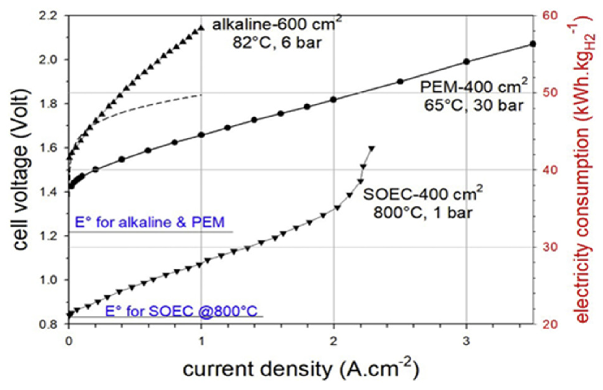
2.1.4. Characteristics of the Different Water Electrolysis Technologies

Table 1 lists the main characteristics of the various electrolyzer technologies, their advantages, and some disadvantages.
According to Table 1, AEL and PEMEL are the two electrolyzer technologies that can currently be exploited for large-scale hydrogen production. However, even though PEMEL technology is more adapted for combination with renewable energies due to its good dynamic responses, it has several drawbacks that prevent it from further development, including the high investment costs associated with using noble metals and a short lifespan. Nevertheless, according to [28], most experts predict that PEMEL systems will replace AEL systems by 2030 due to the latter’s competitive costs and increased operational flexibility. This is because the majority of large-scale hydrogen production systems use AEL technology. In addition, experts predict that unless SOEL systems reach a lifespan and cost level comparable to AEL and PEMEL systems by 2030, they will remain preferable. AEL technology continues to be the most economical method for hydrogen manufacturing since it is the most developed, has the lowest investment cost, has a steady operation, and offers a long lifespan.

2.1.5. Behavioral Aging Model of the Electrolyzer

During their operation, constant, dynamic, and rapid variations in current; voltage peaks; temperature fluctuations; high pressures; the quality of water used in the electrolysis process; and other factors contribute to the degradation of the components and the system. These factors accelerate the aging process of the electrolyzer, which is typically characterized by a significant decrease in efficiency [35,36]. The aim of this part of the work is to review the state-of-the-art in behavioral models of alkaline and proton exchange membrane electrolyzer aging.

Behavioral Aging Alkaline Electrolyzer

F. Gambou et al. [37] reviewed the modeling of AEL from the electrical domain perspective, as well as a modeling approach considering the temperature and mass fraction of KOH or NaOH, as their performance is closely linked to the specific conductivity of the electrolyte in aqueous solution. Static and dynamic tests were carried out on a 150 W alkaline electrolyzer in the laboratory, and an electrical circuit model of a cell (Figure 4a) was then proposed to describe the electrolyzer’s static and dynamic behavior. The authors in [37] advise using techniques such as regression analysis to evaluate the model parameters based on various circuit equations and experimental data when determining the equivalent circuit parameters, because these parameters are influenced by a number of different factors (pressure, temperature, and current). Ursúa et al. [38] analyzed the steady-state and transient behaviors of a “zero-gap” design for a 5 kW AEL. In order to reproduce the behavior of the electrolyzer, a static characterization (Figure 4b) and a dynamic characterization (EIS) with a direct current admitting a 5% IDC disturbance were used. These characterizations have permitted the representation of the polarization curve using 16 empirical coefficients and the determination of parameters such as resistances (linked to charge transfer and electrolyte) as well as capacitances (linked to the double layer phenomenon), both at the anode and cathode. A. Iribarren et al. [39], following a multi-physics approach, developed a dynamic alkaline electrolyzer model in Matlab/Simulink, and validated it with empirical data from [38]. This model incorporated a gas production model, a temperature model, and an electrochemical model. S. F. Amireh et al. [40] evaluated respectively the influence of current ripples on the efficiency of an AEL during operation under variable load conditions, as well as the efficiency of the power supply (six-pulse thyristor converter). Electrochemical models in laboratory-scale, based on a semi-empirical approach, were adopted for the electrolyzers developed. Electrochemical impedance spectroscopy (EIS) and chronopotentiometry were used for characterization at the laboratory scale for two industrial-scale electrolyzers (Lurgi electrolyzer and BTU Cottbus electrolyzer). The models for the industrial electrolyzers were built using altered voltage performance data and ohmic resistances, because EIS is based on low amplitude currents. The capacitive contribution was determined based on the electrode materials using data from experiments and the literature.
Figure 4a,b shows the electrochemical behaviour of the electrolyzer. In Figure 4a, the resistances R a , R c , R m , and R e l e correspond respectively to the contact resistances at the anode and cathode, membrane resistance, and electrolyte resistance. The terms C d l , a and C d l , b , and V a c t , a , E and V a c t , c ,   E represent the double-layer capacities at the anode and cathode, as well as the potential associated with the charge transfer phenomenon. In Figure 4b, resistances R a , R c , R m , and R e l e are symbolized by a singular R o h m , E to represent the ohmic voltage drop at the anode and cathode, while the rest remains unchanged.
It is important to note that there have not been many studies on the behavior modelling of alkaline electrolyzers. This study is hampered by a number of issues, including the system’s complexity. The complexity of the model is increased by including all physico-chemical events that occur during operation in order to accurately represent the behaviour of the electrolyzer. Another difficulty, particularly for high-power electrolyzers used on an industrial scale, is the lack of experimental data. This calls for the adoption of a number of assumptions. Furthermore, there is a complete absence of industrial standards for extrapolating results from laboratory-scale electrolyzers to those operating at an industrial scale (dynamic behavior).

Behavioral Aging Proton Exchange Membrane Electrolyzer

Hernández-Gómez et al. [41] summarized and analyzed various models (static, semi-empirical, empirical, and dynamic) of a 400 W PEMEL. The electrical-circuit-based model was used to understand the dynamic behavior when fed with a dynamic current profile, due to its accuracy (maximum response error: 4%). Methods for extracting circuit parameters that take into account operating conditions were not established. Majumdar A. et al. [42], using different PEMEL models, aimed to improve the transient response using different control mechanisms. The equivalent electrical circuit model used predicted the cell voltage with reasonable accuracy but could not be used to assess behavioral aging. Dang J et al. [43] analyzed the impact of control modes on transient behavior during the charge regulation process, conducted a comparative study, and examined the transient behavior of different shutdown modes based on a dynamic model of three PEMELs (electrical circuit-based models). The parameters of the dynamic model were identified around an operating point on the polarization curve following a current variation. As a result, current control (as opposed to voltage control) was found to be more suitable, due to its stability and ease of implementation. Guilbert D, Vitale G [44] designed a dynamic emulator for a 400 W PEMEL using an equivalent electrical model to test the performance of the power converter supplying the electrolyzer. By means of experiments, the parameters were identified using a least-squares algorithm. The emulator was able to correctly reproduce the responses of the experimental model. The works developed in [45,46] also address the dynamic modeling of PEMEL without considering behavioral aging. Martinson C. A. et al. [41], on the basis of an equivalent electrical circuit model, used the current interruption method to determine the electrochemical characteristics of a PEMEL. This method enabled the determination of various losses and the construction of Nyquist diagrams, which illustrate the double-layer impedance and facilitate the assessment of degradation under specific operating conditions.
Similar to AEL, several factors such as current variation, temperature, pressure, and more accelerate the aging process of PEMELs. However, less work has been performed on the behavioral dynamics of PEMEL aging, as most studies focus on specific operating points to predict their behavior, limiting their applicability in certain operating conditions. To ensure proper operation when connected to renewable energy sources, it is necessary to establish models that account for behavioral aging both at the laboratory and industrial scales for large-scale hydrogen production and controlled degradation of the PEMEL.

2.2. Fuel Cell Technologies

A fuel cell (FC) is an electrochemical conversion device that converts the chemical energy of a fuel (hydrogen) into electrical energy, without producing gas emissions (advantageous for the energy transition), noise, or vibrations, making it an ideal component for many applications [47]. The first functional FC dates back to the 1800s, thanks to the work of Sir William Grove. He duplicated the reverse process of electrolysis by combining hydrogen (H2) and oxygen (O2) to produce electricity through his experimental demonstration of water electrolysis [48]. It was not until 1959, when this field of study advanced, that the Englishman Francis Thomas Bacom presented the first completely functional FC [36,49].
Nowadays, fuel cells are fully commercialized and have found applications in several fields, including transport, stationary, portable, energy cogeneration, and electric power generation, with modules ranging from a few kWs to several MWs. Among the different FC technologies, only six are used explicitly for electricity generation, and these are the ones considered in this paper. These include proton exchange membrane fuel cells (PEMFCs), solid-oxide fuel cells (SOFCs), alkaline fuel cells (AFCs), direct methanol fuel cells (DMFCs), phosphoric acid fuel cells (PAFCs), and molten carbonate fuel cells (MCFCs) [50]. An FC consists of an electrolyte, an anode, a cathode, and an external circuit, as illustrated in Figure 5.
Usually, hydrogen is delivered to the anode, where it oxidizes to form a proton and an electron. Protons pass through the electrolyte to the cathode, while electrons move along the external circuit, producing electricity. At the cathode, oxygen from the air is reduced to oxide, which reacts with protons and electrons to create water and heat. The tank receives a recirculation of any extra hydrogen that is not used up during the process [50,51]. The following equations depict the reactions at the anode (1) and cathode (2), respectively, at the negative electrode (hydrogen) and the positive electrode (air oxygen), as well as the total reaction (3) [51]:
2 H 2 4 H + + 4 e
O 2 + 4 H + + 4 e 2 H 2 O
2 H 2 + O 2 2 H 2 O + E n e r g y ( E l e c t r i c a l + T h e r m a l )
The operating temperature (low, medium, and high) of the FC, the type of electrolyte used, the degree of purity, and the kind of fuel utilized as an energy carrier, are a few of the ways in which they differ from one another [52].

2.2.1. Alkaline Fuel Cell Technologies

Alkaline fuel cells (AFCs) typically run at low temperatures (between 23 and 70 °C) with pure hydrogen serving as the fuel and pure oxygen acting as the oxidant [53]. They employ a liquid solution of KOH or NaOH as the electrolyte. The anion exchange membrane fuel cells (AEFCs), which make use of a solid polymer electrolyte, are another type of alkaline fuel cell. Due to its high conductivity, potassium hydroxide (KOH) is the most commonly utilized electrolyte in AFCs.
The oxidation reaction of hydrogen, which is supplied at the anode, is then aided by these hydroxide ions as they diffuse into the electrolyte, producing water and electrons [54]. The main advantages of AFCs are their high efficiency, yields of up to 0.6, easier heat management, quick start-up, higher activity, relatively low cost, and rapid reaction kinetics for oxygen reduction. However, there are several disadvantages associated with this technology. The corrosive nature of the liquid KOH electrolyte makes it challenging to maintain a gas-tight seal between the anodic and cathodic gases. AFCs also have a low tolerance for CO2, which is a chemical byproduct in the case of hydrocarbon fuels. KOH absorbs CO2, which lowers the electrolyte’s conductivity and negatively affects performance and efficiency [50,53].
The Gemini space program for the Apollo missions used AFC, with specifications such as an extreme Pt load of 40 mg/cm2, an 85% by weight KOH concentration, and temperatures exceeding 100 °C at a pressure of 3 bars applied to 93 cells distributed among 3 FCs connected in parallel, resulting in a 4.5 kW AFC [54]. These are some examples of the application of AFC technologies in specific production facilities. Currently operating companies supplying AFC solutions include the UK-based company AFC Energy and GenCell Energy in Israel. While the former still supplies AFCs at the > 10 kW to > MW scale, GenCell announced in 2018 a commercial system including a 4 kW AFC employing cracked ammonia (99.5%) as a hydrogen source (Project Alkammonia) [54,55] for a stationary off-grid power supply. AFC Energy is a leading partner, as all their standard configurations have the cracked ammonia as a fuel option.

2.2.2. Direct Methanol Fuel Cells (DMFCs)

DMFCs are low-temperature FCs, operating between 60 and 130 °C, that directly use a fuel other than hydrogen, unlike most other fuel cell technologies [50]. The electrode-membrane assembly, which is the main element of this technology, is created and arranged similarly to that of polymer electrolyte membrane fuel cells (PEMFCs), with the exception that the byproducts of DMFC processes contain carbon dioxide. A polymer membrane serves as the electrolyte in DMFCs, similar to how it does in PEMFCs. However, the method is made simpler by eliminating fuel reformation, by taking hydrogen directly out of liquid methanol [50,56]. An aqueous methanol solution is oxidized at the anode during DMFC operation, producing carbon dioxide and protons. It then discharges CO2 into the anode structure. The protons generated at the anode pass through the solid polymer electrolyte (Nafion), while the electrons produced flow from the anode to the cathode through the external circuit. At the cathode, the electrons and protons combine with the oxidant (air or oxygen) to produce water (reduction) [56,57].
DMFCs offer efficiencies of around 40% at an operating temperature of 130 °C. This low efficiency is attributed to the “methanol crossover”, which is the cause of non-productive methanol consumption in the process [57]. DMFCs offer several advantages, such as short start-up time, cost-effective use of methanol, ease of production, direct utilization of methanol in the FC operation, high energy density, and ability to power small-scale installations (<5 KW), mobile devices, and laptops. However, the main disadvantage associated with this technology is its low efficiency, around 40%, making it the least efficient among FC technologies. Additionally, the catalysts employed in DMFCs are based on precious and expensive metals such as Pt and Ru [50,53].

2.2.3. Phosphoric Acid Fuel Cells (PAFCs)

Phosphoric acid fuel cells (PAFCs) are intermediate-temperature (medium) FCs that operate within a temperature range of 150 to 220 °C, utilizing a liquid phosphoric acid electrolyte, H 3 P O 4 [50,58]. The materials used in PAFCs include platinum or platinum-ruthenium for the anode and platinum for the cathode. The energy efficiency of this technology varies between 35% and 40%. However, when employed in energy cogeneration applications, the efficiency can reach around 85% [59,60]. Mainly developed for small and medium power station applications (50 KW to 11 MW), PAFCs have the advantage of a simple structural design and lower sensitivity to CO poisoning and electrolyte volatility, employing suitable cell construction materials and ensuring stable operating conditions. Disadvantages include low power density and high material costs, due to the corrosive nature of phosphoric acid [50,53,58,60].

2.2.4. Molten Carbonate Fuel Cells (MCFCs)

MCFCs are classified as high-temperature fuel cells, operating from 550 °C to 700 °C. Their electrolyte consists of molten carbonate salts, primarily lithium, potassium, or sodium carbonates [53]. These fuel cells offer a high energy efficiency of approximately 60%, which can reach up to 85% in hybrid cycles with cogeneration. Various fuel types can be utilized in MCFCs, including hydrogen, natural gas with oxygen or carbon dioxide as oxidant, and other hydrocarbons [51,53]. Due to their high operating temperature, MCFCs do not require noble catalysts such as platinum. Nickel is commonly used as a catalyst, reducing material costs and contributing to overall system profitability. The high operating temperature also enables reforming processes, as MCFCs can be directly fueled by natural gas and obtain the necessary hydrogen for the internal reaction. Disadvantages include extended start-up time, corrosion, and electrolyte degradation. These fuel cells are suitable for stationary power generation (providing outputs of between 0.1 and 2 MW) and in hybrid cogeneration systems, to enhance energy efficiency [50,59,60].

2.2.5. Solid-Oxide Fuel Cells (SOFCs)

SOFCs are high-temperature FCs with an operating temperature range of 600 °C to 1000 °C. Their electrolyte is composed of solid ceramic material, specifically yttrium-stabilized zirconia [53,61]. Because of the high operating temperature, the cathode’s materials must meet specific requirements for thermal stability, stable ionic conductivity, and catalytic activity. Typically, lanthanum strontium manganite (LSM) and yttrium-stabilized zirconia-nickel (Ni-YSZ) are used for the cathode and anode, respectively [36]. Thanks to their flat or tubular design, this technology can achieve energy efficiencies of >60% and even 85% in the case of cogeneration applications, by utilizing the excess heat generated during the process. This technology assists the reforming process, enabling direct fuel supply to the FC, similar to MCFCs.
It also offers the possibility of using several fuel types, such as natural gas, hydrogen, propane, etc. These fuel cells have found applications in portable systems, stationary power generation ranging from a few KWs to several MWs, and energy cogeneration systems [50,53,60].

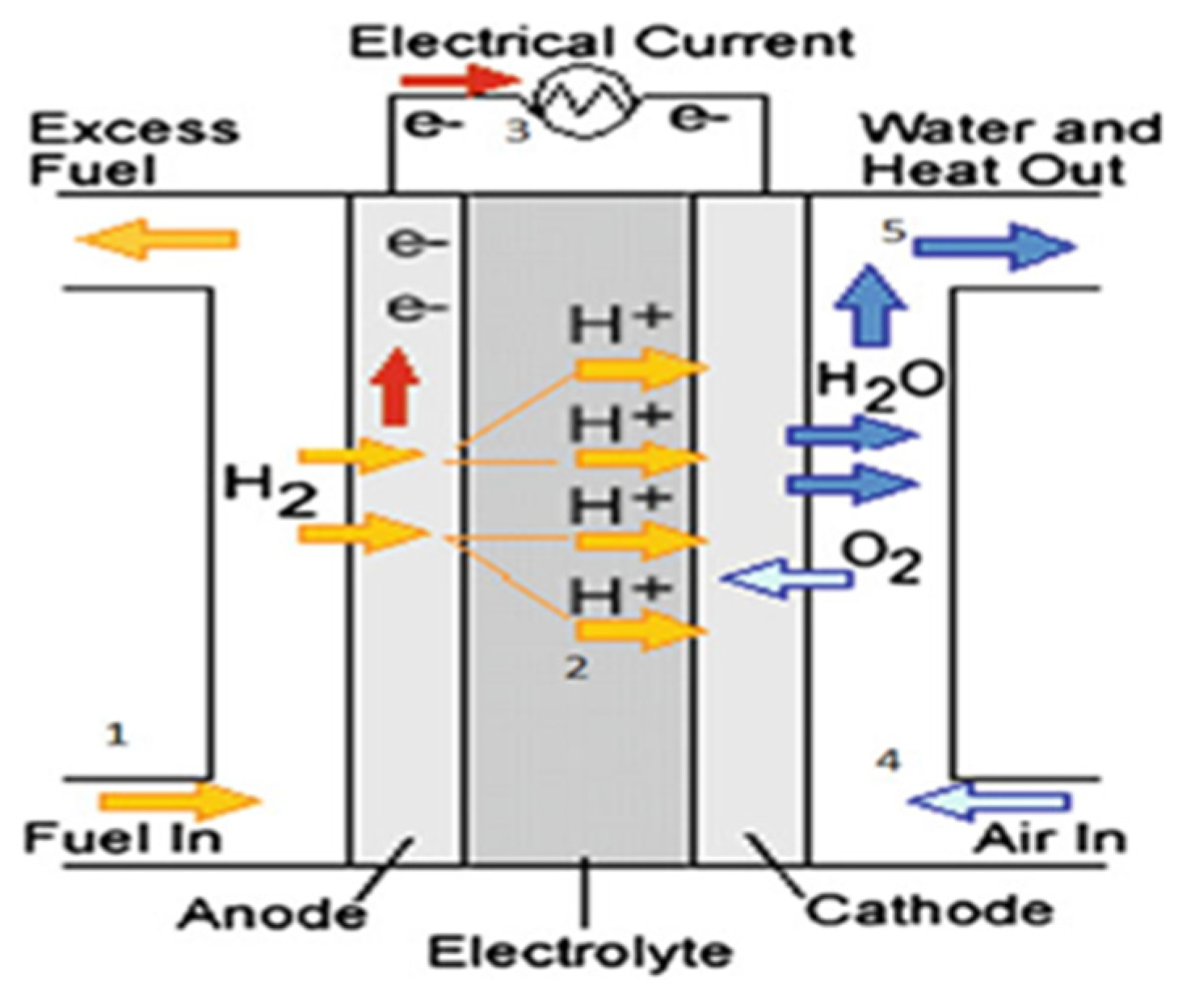
2.2.6. Proton Exchange Membrane Fuel Cells (PEMFCs)

Proton exchange membrane fuel cells (PEMFCs) come in two categories: low-temperature PEMFCs and high-temperature PEMFCs [62]. They differ in terms of membrane composition and the materials used for the anode and cathode. In the case of low-temperature PEMFCs, the membrane or electrolyte is in the form of a solid polymer, with an operating temperature of between 70 and 80 °C, porous carbon electrodes (an anode and cathode, composed respectively of platinum or platinum-ruthenium and platinum) and a platinum catalyst. In high-temperature PEM-FCs, the membrane is composed of phosphoric acid-doped polybenzimidazole (PBI), with an operating temperature of around 200 °C and electrodes made of carbon-supported platinum-ruthenium.
Compared to the low-temperature technology, the high-temperature PEMFCs are more tolerant of carbon monoxide and facilitate the utilization of heat produced in combined heat and power (CHP) cycles [60,63].
With energy efficiencies ranging from 40 to 60%, these FCs offer high power density, a compact and simple structure, rapid startup capabilities, a wide power range from mWs to KWs, and scalability. This technology is used in various applications across diverse fields such as transport, aeronautics, stationary, power generation, etc. However, it also has several drawbacks, such as the need for high-purity hydrogen fuel, slow oxygen reduction kinetics, and high cost due to using platinum as a catalyst [50,53,63,64].

2.2.7. Characteristics of the Fuel Cell Technologies

Table 2 below summarizes the characteristics of the FCs that have been developed in [53,65,66].
Based on an analysis of Table 2 results and the application environment (distributed generation and transportation), it can be inferred that FC technologies such as PEFC, PAFC, MFC, and SOFC are especially well-suited to these particular domains. However, it is evident that efficiency is still constrained at less than 80% from a system perspective. When FCs are integrated into energy cogeneration systems, particularly those that operate at elevated temperatures (PEFC, PAFC, MFC, and SOFC), optimal performances are attained. The maximum efficiencies, however, are shown by AFC and SOFC, at 62% and 60%, respectively. PEMFCs are distinguished economically by having lower costs compared to other FCs, which have greater expenses. When considering sustainability in terms of operating hours, most cells show durabilities greater than 4000 h, although this depends on the specifics of the operation.
Finally, because the hydrogen used by many FC technologies comes from RESs, MCFCs, which are good at producing large quantities of power, produce carbon dioxide when reacting hydrogen with their molten carbonate electrolyte. Therefore, this technology cannot be used, as the objective is to achieve carbon neutrality by 2050. However, unless a CO2 capture device—which can produce hydrogen (H2) through a transformation process that can be reused in the system [67]—is integrated into MCFCs, the system will remain bulky and tedious to model, and it will suffer from a significant increase in system costs. PEMFCs, SOFCs, and PAFCs are also suitable for large-scale electricity production. However, compared to PAFCs and SOFCs, PEMFCs have a high power density, high efficiency, rapid response times, low weight, no corrosive fluid, adaptability to dynamic load variations, and wide power range (ease of scaling), making them a priority over SOFCs and PAFCs [63,65].

2.2.8. Behavioral Aging Model of the Fuel Cells

For ensuring re-electrification through FCs for energy injection into the grid, PEMFCs and SOFCs are best suited. However, these SOFCs undergo degradation during their operation due to severe operating conditions, typically influenced by temperature, current ripple, pressure, and others. The degradation mechanisms of each component of the SOFC (anode, cathode, and electrolyte), the characterization techniques, and the durability have been studied in a review by S. Zarabi Golkhatmi et al. [68]. SOFCs had the largest lifespan and low manufacturing costs; however, beyond 1000 h of operation, a voltage loss in the fuel cell and a substantial increase in its resistance were observed. To enhance performance and durability, various electrochemical characterization tools (I–V measurement, EIS, and calendar-life tests), structural characterizations, and chemical characterization techniques (Raman spectroscopy, FT-IR, XRD, XPS, SIMS, TGA, DSC, dilatometry, and microscopy techniques) have been developed. However, the complexity of this characterization process hinders definitive conclusions regarding long-term durability and stability, as the need for a standard for extrapolating the results obtained from laboratory-scale solid-oxide fuel cells to those operating on an industrial scale remains a barrier to understanding their aging process. Moreover, the high operating temperature of SOFCs poses challenges for their integration into the electrical grid.
The PEMFC behavior description models based on electrical circuits are summarized by M. Nabag et al. in their study [69]. They proposed a dynamic model of the FC based on the Randles circuit to evaluate the effects of current harmonics on its efficiency and durability. Through characterization conducted on a 12-cell stack, they demonstrate that low-frequency ripple currents applied to the PEMFC over an extended characterization period accelerate the aging of the FC due to cathodic flooding and membrane drying. K. J. Runtz et al. [70], similar to [54], also established electrical circuit-based models of PEMFCs. To assess the potential performance degradation of the cell when in passive mode, passive models of the cell are also displayed in addition to dynamic models. Fardoun et al. [71] evaluated the impact of current ripple and oxygen compression on a 1.2 kW PEMFC (modeled by A. M. Dhirde et al. in [72]).
The FC characterization method based on EIS allowed impedance to be plotted in the Nyquist plane, along with the evolution of FC parameters (resistances and double-layer capacitances). The model was validated by comparing the measured curves with those fitted using the Levenberge–Marquardet algorithm, which is a non-linear least-squares fitting algorithm. The compressor, with its slow voltage dynamics resulting from a dynamic current load profile imposed on the FC, was modeled and added to the FC model, thereby improving the FC voltage response. T. Jarry et al. [73] evaluated the impact of high-frequency current ripples on the degradation of a high-temperature PEMFC consisting of four cells, through characterization tests such as polarization curve, EIS, and cyclic voltammetry measurements over a period of 2600 h. Among these four cells, two cells operated with a triangular current profile (dynamic model), while the other two cells operated with a constant current (quasi-static model). The study demonstrated that high-frequency current ripple did not significantly affect the specific degradation of the FC throughout the specific test period. Emmanuel et al. [74] analyzed the impact of the relative humidity gradient and pressure gradient on PEMFC performance, using a model based on the cell’s electrical circuit, I–V polarization curve characterization, and EIS, to observe the cell behavior of the FC by extracting circuit parameters such as mass transfer resistance, electrolyte resistance, and double-layer capacitance as a function of the current density and relative pressure. The study demonstrated that high relative humidity at the anode reduces membrane and electrolyte resistance due to higher water content in the membrane, improving FC performance. Compared with the anode, high relative humidification at the cathode improves cell performance at low current densities (reduced ohmic polarization). On the other hand, the higher the pressure gradient in the anode-cathode direction (low pressure at the anode, high pressure at the cathode), the better the cell’s performance in dry conditions, and vice versa in the cathode-anode direction, regardless of the conditions (wet or dry). K. Meng et al. [75] analyzed the impact of dynamic cycling on the degradation of a PEMFC through characterization techniques such as polarization curve, EIS, and cyclic voltammetry (CV) measurements. The results show that cell degradation accelerates with increasing cyclic charging rates, mainly due to the lack of hydrogen and oxygen in the charging process. Y. Zhai et al. [76] analyzed the impact of sulfur dioxide (SO2) on the performance of a PEMFC. EIS and an electrical circuit model were used to observe the effects of SO2 on the electrochemical reactions at the cell cathode. The study revealed that during the irreversible SO2 poisoning phase, sharp increases in charge transfer resistance and diffusion resistance were observed, leading to a decrease in FC performance.
Several studies have been conducted on the behavioral aging of PEMFC, using various characterization methods (as summarized in [77]) to determine the impact of operating conditions on FC degradation. Since EIS is a characterization method based on low-amplitude currents, high-power PEMFC (approx. 500 kW) cannot be characterized using this method. Therefore, the fuel cells studied in most of the literature are low-power or based on a few cells. It is imperative to apply a scaling factor when comparing laboratory results to those of large-scale operating fuel cells, and to then apply series-parallel associations to achieve the system’s required power and operating voltage. Generally, most analyzed systems do not consider the combined impact of different degradation factors. It is, therefore, imperative to incorporate various effects that may accelerate fuel cell aging within the system, to further improve its performance by controlling these parameters that accelerate their degradation.

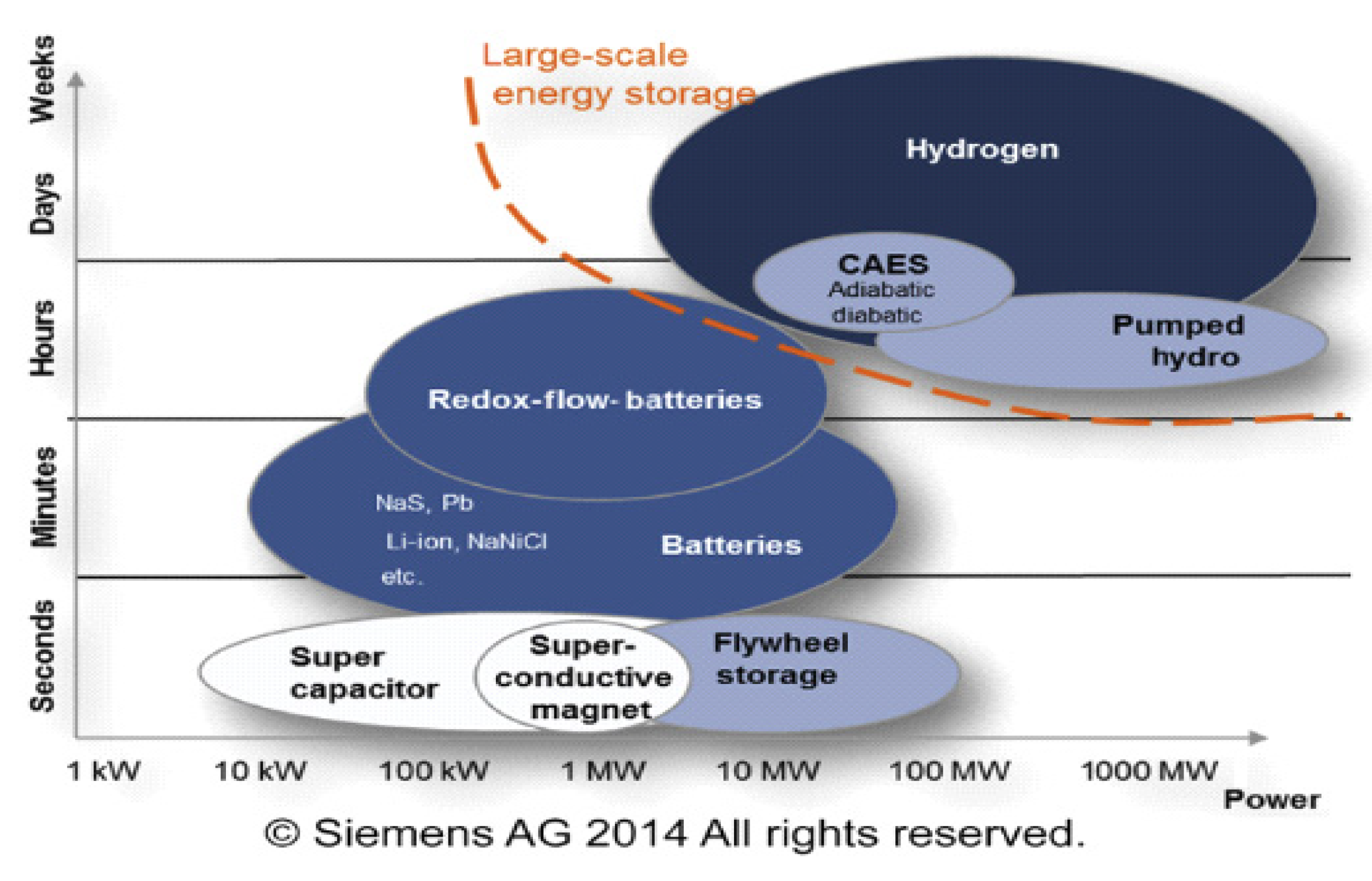
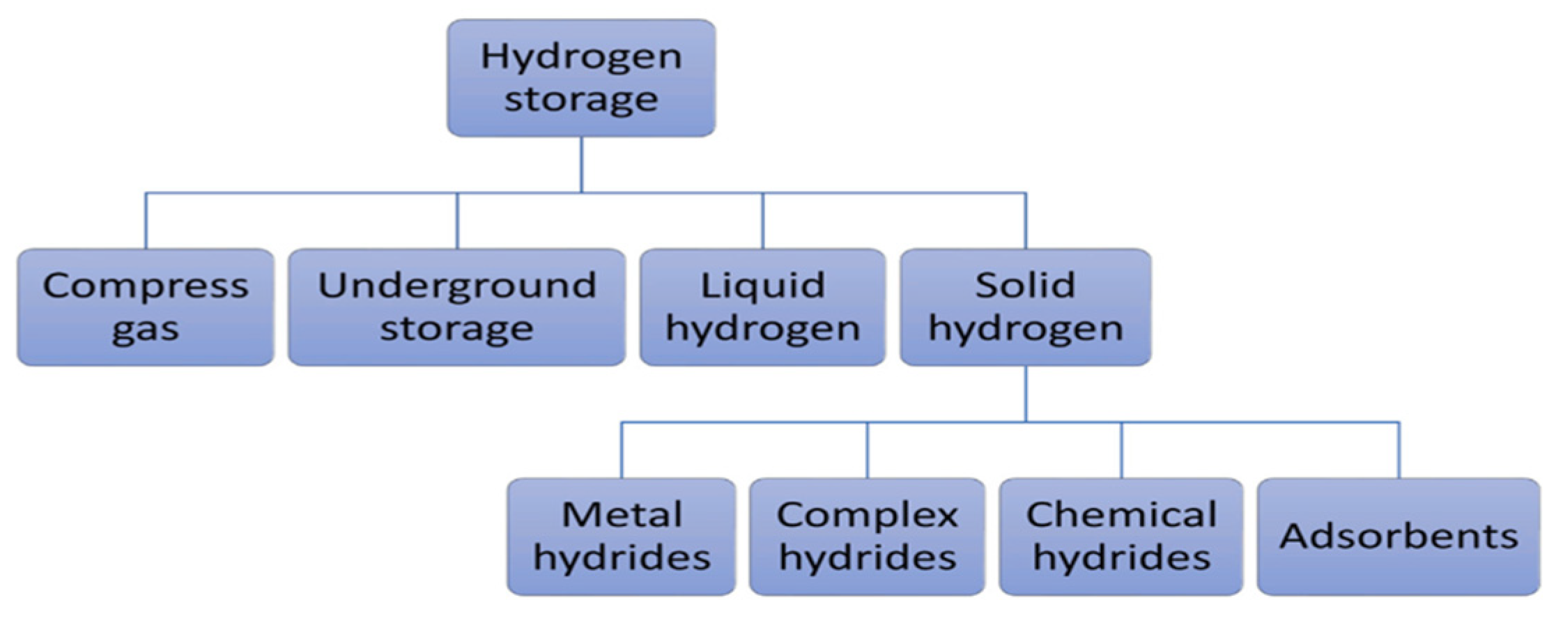
3. Hydrogen Storage Units in Hydrogen Production Systems

Figure 6 illustrates different energy storage technologies. It can be observed that energy storage technologies such as super-capacitors or flywheels are used to store a limited amount of power quickly and deliver it quickly. In contrast, energy storage technologies such as compressed air energy storage (CAES), pumping hydroelectric energy storage (PHES), or hydrogen storage are used on a large scale [78]. Developing large-scale hydrogen storage technologies will play an essential role in the energy transition. Different hydrogen storage technologies include high-pressure compressed gas, cryogenic liquid at very low temperatures, and solid-state and underground storage [13,79,80]. Figure 7 summarizes the other hydrogen storage technologies. The choice of a specific technology depends on factors such as the volume of storable hydrogen, duration, discharge rate, location, and cost.

3.1. Compressed-Gas Hydrogen Storage

The most common method of storing hydrogen directly is to store it in gaseous form at high pressure to reduce storage volume, since storage capacity is proportional to volume. Due to its very low density of approximately   0.089   k g / m 3 , hydrogen needs to be stored at high pressures. Currently, pressures of 25–35 MPa are used for storage (for fuel cell applications) and transport, and they can reach 70 MPa [81,82]. However, as pressure increases, this hydrogen compression process consumes excessive energy, leading to an increase in overall system cost [83]. This storage technology has limitations, including storage capacity being limited by the weight of the tanks and the high price of materials used for their design. These tanks require materials with specific properties, such as high thermal conductivity, and a structural design that can handle the increased internal temperature, to mitigate accelerated aging [13,81].

3.2. Underground Hydrogen Storage

Underground hydrogen storage stands out from the others because of the considerable volume of gas stored, the moderate or extended storage time, and the high capital investment required to build underground storage facilities [84]. There are various solutions for storing hydrogen underground: aquifers, natural gas, oil deposits (preferably already depleted), and salt caverns. These enable large-scale, medium- to long-term hydrogen storage [13,84,85]. However, the first two solutions may impact gas compositions because hydrogen can enter spaces that still contain many residual hydrocarbons, which is not beneficial for fuel cells for reconversion, as the discharged hydrogen may have unpredictable compositions. Salt caverns have attracted a great deal of interest compared with the other two, as they have incredibly high wall tightness, high operating pressures (maximum: 200 bar) at depths of up to 2000 m, geometric volumes of 500,000 m3 or more, a small footprint, low specific investment costs per MWh of storage, and low dependence on geological conditions [78,84,85,86]. Typical design parameters for a cavern with a depth of 1000 m include a volume of 500,000 m3 and a pressure ranging from 60 to 180 bar, representing a storage capacity equivalent to 80 GWh of electrical energy. One limitation to the expansion of this technology is that it is concentrated in areas or regions with significant salt deposits, which are not uniformly distributed [13,84].

3.3. Liquid Hydrogen Storage

In its liquid form, hydrogen has a much higher density, considerably increasing its volumetric energy density. The density of liquid hydrogen reaches around 71 g/L at −253 °C, where its energy density is equal to 8 MJ/L·H2 [79,81]. Hydrogen is liquefied at −253 °C (the boiling point of hydrogen) to be stored at low pressure in liquid form in tanks; its size is reduced due to its higher density, which is 1.5 to 2 times greater than that of compressed hydrogen at high pressure. Liquefied hydrogen’s global installed storage capacity is approximately 355 tons per day (tpd). Furthermore, today’s largest liquefaction plant has a capacity of 34 tpd. However, this hydrogen liquefaction process is very energy-intensive, requiring around 30 to 40% of the stored gas energy to be invested in the process, resulting in a considerable increase in costs. The problem of vaporization of escaping hydrogen is estimated at a rate of 1.5 to 3% per day, and the volume and weight of the tanks are also significant drawbacks of this system. Currently, liquid hydrogen has not been widely commercialized and is primarily reserved for special applications such as space travel [13,81,82,83,84,85,86,87].

3.4. Solid Hydrogen Storage

Storing hydrogen in solid form solves the problems encountered in storing hydrogen in liquid form (evaporation and energy requirements) and gaseous form at high pressure (storage capacity due to tank weight, cost of materials, and energy requirements). Hydrogen can be combined physically or chemically with certain solid materials to store it in a solid state by absorption or adsorption [13,81,88]. Absorption allows hydrogen to be stored directly in the mass of the material to form hydrides (metallic, complex, and chemical hydrides). Metal hydrides (Ni, Li, Na, Mg, B, Al, etc.), compared with complex hydrides (NaAlH4, NaBH4, LiAlH4, LiBH4, Mg(AlH4)2, LaNi5H6, NH3BH3, NH3BH3, etc.) and chemical hydrides (LiH, NaH, MgH2, etc.), have attracted considerable interest, due to their excellent hydrogen storage capacities, including a high degree of safety, reversibility of hydrogenation/dehydrogenation, volumetric energy densities of hydrogen (about three times higher than liquid or gaseous storage), low-pressure equipment, and low energy requirements for stationary applications [78,88,89]. Several studies have been carried out in the literature in terms of dynamic modeling for static and dynamic characterization [90,91]. For the large-scale storage of metal hydrides, efforts are needed to reduce material costs, address the low mass density issue, improve hydrogen kinetics, and enhance the thermal management of the system [13,88].
Physical adsorption, also known as physisorption, enables hydrogen to be stored by adsorption, by exploiting the Van Der Waals bonds between molecular hydrogen and a material with a large specific surface area. The materials most commonly used for hydrogen storage by adsorption are porous carbon-based materials, metal-organic structures, porous polymeric materials, and zeolites [13,79,89]. Despite their reversibility and rapid kinetics, these materials have a low hydrogen storage capacity under ambient conditions, requiring extremely low temperatures for high storage capacity. This constraint significantly limits the practical use of these materials in various applications. The low hydrogen storage capacity through adsorption hinders its commercialization [13,92].
In [93], an economic analysis was conducted on large-scale hydrogen storage processes. The study provides a detailed economic analysis of the cost of hydrogen in one of the French regions and the case of underground storage in France; it revealed that the cost of hydrogen storage ranges from 4.5 EUR/kg to 6.6 EUR/kg H2, with underground mass storage costs remaining below 5% of the overall costs. In [94], a technical and economic analysis was conducted on large-scale hydrogen production facilities in five Canadian regions, producing approximately 4000 to 40,000 kgH2/day, or around 10 to 100 MW. The study also compared two hydrogen storage processes and analyzed the associated costs. Results showed that existing underground salt caverns had a relatively lower investment cost of USD 18.70/kgH2 compared to metal tanks with an investment cost of USD 720/kgH2 for hydrogen storage. It was also noted that the cost of hydrogen storage units is influenced by various factors, such as technological, operational, geographical, and economic factors.
For large-scale hydrogen storage, various storage technologies have been employed, including hydrogen compression and liquefaction. However, these methods have limitations in terms of storage volume and safety concerns, due to the highly flammable nature of hydrogen gas. To address these issues, underground hydrogen storage is a viable option as it offers high storage volume and is well-suited for large-scale hydrogen storage. Another interesting option is solid-state hydrogen storage, which directly stores hydrogen in chemical or physical form within solid materials that can absorb and release hydrogen reversibly. This technology has several advantages, such as high storage capacity, improved safety, and reduced tank weight, which can help solve the storage volume problems associated with traditional storage methods.

4. Different Projects Realized or Currently Underway on Large-Scale Hydrogen Production

This section identifies the currently operational or ongoing power-to-gas projects in Europe, to analyze the technological development of renewable energy-based hydrogen production systems. The PHOEBUS project was one of the first power-to-gas projects in Europe (1993–2003), located in Jülich, Germany. This project aimed to study hydrogen storage as an energy carrier produced through electrolysis coupled with a photovoltaic field [95]. Since then, several other projects have been carried out worldwide.
The GrInHy project aims to supply green hydrogen by electrolysis using renewable electricity and to provide grid management services as a reversible generator at the Salzgitter Flachstahl GmbH (Salzgitter, Germany) steelworks. A reversible solid-oxide electrolyzer (RSOEL) was scaled up with 150 KWel electrolysis power and 30 KWel output power in reversible mode (FC operation with hydrogen), respectively, using 25 KWel with natural gas. After 5000 h of operation, the efficiency targeted by the project was 80% LHV in electrolyzer mode, which achieved 78% LHV at a flow rate of 40 Nm3/h. In the fuel cell mode fueled by natural gas, the prototype supplied electricity to the grid with an efficiency of 50% LHV. The system also showed a degradation rate of less than 1%/1000 h, which made it possible to predict its long-term functionality. The project started on 1 March 2016 and was completed on 28 February 2019 for EUR 4,498,150 [96].
The ROBINSON project aims to decarbonize industrialized islands by developing an integrated, intelligent, and cost-effective energy system that combines thermal, electrical, and gas networks to optimize the use of local RESs. Through the development of a smart, modular, and optimized energy management system (EMS), the project will integrate existing and newly developed technologies, such as a micro-gas turbine for combined heat and power generation, an anaerobic digester assisted by bio-electrochemical systems for converting liquid waste into bio-methane, an innovative mobile wind turbine, a gasifier for recycling biological waste, and hydrogen-related technologies (electrolyzer and storage system). The studies took place in Eigerøy, with a total duration of 48 months starting in 2020, and the European Union funds the budget of EUR 8.37 million. This integrated system will ensure a reliable and cost-effective energy supply while contributing to the decarbonization of European islands by helping to reduce CO2 emissions [97,98].
The Jupiter 1000 project is France’s first power-to-gas project on the natural gas transmission network. Located in Fos-sur-Mer, this project ensures the production of green hydrogen through 500 W PEMELs and AEL electrolyzers, both coupled with RES. The capture of CO2 on the chimneys of a nearby industrial plant also enables, after a methanation process, the production of SNG (substitute natural gas) of renewable origin, which can be mixed with hydrogen and then injected into the natural gas transport network. The project officially began in 2016 and ended in 2019, with an investment cost of EUR 30.8 million partially funded by the FEDER (European Regional Development Fund), the PACA region, and funds from the ADEME (French Environment and Energy Management Agency) Future Investments Program. The plant is designed to produce up to 25 Nm3/h of synthetic methane or 200 Nm3/h of hydrogen, with an average production of 5 GWh over three years [97,99].
Table 3 gives an overview of power-to-gas projects in Europe using only renewable energy sources [100,101,102].
It should be noted that most recent projects use PEMEL electrolyzers to produce hydrogen. This is because PEMEL electrolyzers are more efficient in the face of variations caused by energy fluctuations imposed by RES. However, the alkaline electrolyzer remains a reliable and affordable technology in terms of cost and has a satisfactory service life, which is why it is still widely used today.

5. Conclusions

Producing “green” hydrogen from renewable energy sources aims to decarbonize significant sectors such as transportation, industry, natural gas networks, electricity production, and more. Large-scale hydrogen generation systems are the main topic addressed in this paper. Studies have been conducted to compare the primary technologies for large-scale hydrogen production (electrolyzers), storage hydrogen, and re-electrification (FCs). Improvements in terms of cost, efficiency, durability, and materials used in the design of this equipment are needed to facilitate the broader integration of hydrogen as an energy carrier and to contribute to an energy transition towards a more sustainable and environmentally friendly hydrogen economy.
This paper has also examined behavioral aging models for alkaline, proton exchange membrane electrolyzers, and PEMFC for power-to-gas systems using data from different literature sources. Integrating these behavioral aging models into large-scale hydrogen production systems enables more efficient and sustainable management of this equipment by optimizing their utilization, extending their lifespan, and minimizing maintenance costs. However, behavioral aging models for large-scale electrolyzers and fuel cell systems are limited by the lack of experimental data and standards to extrapolate results from laboratory tests on low-power components. Nevertheless, continuous efforts are being made in the behavioral aging modeling of these systems at a larger scale to improve their accuracy. To show hydrogen’s economic and technical potential as clean energy and to support the transition to more sustainable energy systems, power-to-hydrogen projects at the European scale were presented. The perspective of this work is to establish online or offline energy management strategies that consider the operating conditions of the electrolyzers and FCs, to improve the system’s durability and efficiency, by incorporating the behavioral aging model of battery storage, power electronic converters for energy control and management, and a comparative technical and economic study of hydrogen production solutions.

Funding

This research received no external funding.

Data Availability Statement

Not applicable.

Conflicts of Interest

The authors declare no conflict of interest.

References

  1. Commission, E. The European Green Deal. Eur. Comm. 2019, 53, 24. [Google Scholar]
  2. European Comission. A Hydrogen s for a Climate-Neural Europe. Communication from the Commission to the European Par-Liament, the Council, the European Economic and Social Com-Mittee and Committee of Regions. 2020. Available online: https://eur-lex.europa.eu/legal-content/EN/TXT/?uri=CELEX%3A52020DC0301 (accessed on 4 July 2023).
  3. Genovese, M.; Schlüter, A.; Scionti, E.; Piraino, F.; Corigliano, O.; Fragiacomo, P. Power-to-Hydrogen and Hydrogen-to-X Energy Systems for the Industry of the Future in Europe. Int. J. Hydrogen Energy 2023, 48, 16545–16568. [Google Scholar] [CrossRef]
  4. Ishaq, H.; Dincer, I.; Crawford, C. A Review on Hydrogen Production and Utilization: Challenges and Opportunities. Int. J. Hydrogen Energy 2022, 47, 26238–26264. [Google Scholar] [CrossRef]
  5. Hosseini, S.E.; Wahid, M.A. Hydrogen Production from Renewable and Sustainable Energy Resources: Promising Green Energy Carrier for Clean Development. Renew. Sustain. Energy Rev. 2016, 57, 850–866. [Google Scholar] [CrossRef]
  6. Mali, B.; Niraula, D.; Kafle, R.; Bhusal, A. Green Hydrogen: Production Methodology, Applications and Challenges in Nepal. In Proceedings of the 2021 7th International Conference on Engineering, Applied Sciences and Technology (ICEAST), Pattaya, Thailand, 1–3 April 2021; pp. 68–76. [Google Scholar]
  7. Li, L.; Lin, J.; Wu, N.; Xie, S.; Meng, C.; Zheng, Y.; Wang, X.; Zhao, Y. Review and Outlook on the International Renewable Energy Development. Energy Built Environ. 2022, 3, 139–157. [Google Scholar] [CrossRef]
  8. Scita, R.; Raimondi, P.P.; Noussan, M. Green Hydrogen: The Holy Grail of Decarbonisation? An Analysis of the Technical and Geopolitical Implications of the Future Hydrogen Economy. 2020. Available online: https://papers.ssrn.com/sol3/papers.cfm?abstract_id=3709789 (accessed on 4 July 2023).
  9. Panchenko, V.A.; Daus, Y.V.; Kovalev, A.A.; Yudaev, I.V.; Litti, Y.V. Prospects for the Production of Green Hydrogen: Review of Countries with High Potential. Int. J. Hydrogen Energy 2023, 48, 4551–4571. [Google Scholar] [CrossRef]
  10. Kakoulaki, G.; Kougias, I.; Taylor, N.; Dolci, F.; Moya, J.; Jäger-Waldau, A. Green Hydrogen in Europe—A Regional Assessment: Substituting Existing Production with Electrolysis Powered by Renewables. Energy Convers. Manag. 2021, 228, 113649. [Google Scholar] [CrossRef]
  11. ENTSO-E Transparency Platform. Actual Generation per Production Type. 2020. Available online: https://transparency.entsoe.eu/generation/r2/actualGenerationPerProductionType/show (accessed on 4 July 2023).
  12. Eurostat. Available online: https://ec.europa.eu/eurostat/fr/web/main/data/database (accessed on 4 July 2023).
  13. Yue, M.; Lambert, H.; Pahon, E.; Roche, R.; Jemei, S.; Hissel, D. Hydrogen Energy Systems: A Critical Review of Technologies, Applications, Trends and Challenges. Renew. Sustain. Energy Rev. 2021, 146, 111180. [Google Scholar] [CrossRef]
  14. Meng, Z.; He, Q.; Shi, X.; Cao, D.; Du, D. Research on Energy Utilization of Wind-Hydrogen Coupled Energy Storage Power Generation System. Sep. Purif. Technol. 2023, 313, 123439. [Google Scholar] [CrossRef]
  15. Kumar, K.; Alam, M.; Dutta, V. Energy Management Strategy for Integration of Fuel Cell-Electrolyzer Technologies in Microgrid. Int. J. Hydrogen Energy 2021, 46, 33738–33755. [Google Scholar] [CrossRef]
  16. Wang, J.; Li, D.; Lv, X.; Meng, X.; Zhang, J.; Ma, T.; Pei, W.; Xiao, H. Two-Stage Energy Management Strategies of Sustainable Wind-PV-Hydrogen-Storage Microgrid Based on Receding Horizon Optimization. Energies 2022, 15, 2861. [Google Scholar] [CrossRef]
  17. Fernandez, A.M.; Kandidayeni, M.; Boulon, L.; Chaoui, H. An Adaptive State Machine Based Energy Management Strategy for a Multi-Stack Fuel Cell Hybrid Electric Vehicle. IEEE Trans. Veh. Technol. 2019, 69, 220–234. [Google Scholar] [CrossRef]
  18. Yin, W.; Liu, L.; Rui, X. Analysis, Modeling and Control of a Hybrid Drive Wind Turbine with Hydrogen Energy Storage System. IEEE Access 2020, 8, 114795–114806. [Google Scholar] [CrossRef]
  19. Guo, X.; Zhu, H.; Zhang, S. Overview of Electrolyser and Hydrogen Production Power Supply from Industrial Perspective. Int. J. Hydrogen Energy 2023, 49, 1048–1059. [Google Scholar] [CrossRef]
  20. Jarvinen, L.; Ruuskanen, V.; Koponen, J.; Kosonen, A.; Ahola, J. Effect of Power Quality on PEM Fuel Cells and Water Electrolyzers: A Literature Review with Watson Discovery. In Proceedings of the 2019 21st European Conference on Power Electronics and Applications (EPE’19 ECCE Europe), Genova, Italy, 3–5 September 2019; p. P-1. [Google Scholar]
  21. Guo, Y.; Li, G.; Zhou, J.; Liu, Y. Comparison between Hydrogen Production by Alkaline Water Electrolysis and Hydrogen Production by PEM Electrolysis. IOP Conf. Ser. Earth Environ. Sci. 2019, 371, 42022. [Google Scholar] [CrossRef]
  22. Rashid, M.D.; Al Mesfer, M.K.; Naseem, H.; Danish, M. Hydrogen Production by Water Electrolysis: A Review of Alkaline Water Electrolysis, PEM Water Electrolysis and High Temperature Water Electrolysis. Int. J. Eng. Adv. Technol. 2015, 4, 80–93. [Google Scholar]
  23. Yu, Z.; Duan, Y.; Feng, X.; Yu, X.; Gao, M.; Yu, S. Clean and Affordable Hydrogen Fuel from Alkaline Water Splitting: Past, Recent Progress, and Future Prospects. Adv. Mater. 2021, 33, 2007100. [Google Scholar] [CrossRef]
  24. Smolinka, T.; Ojong, E.T.; Garche, J. Hydrogen Production from Renewable Energies—Electrolyzer Technologies. In Electrochemical Energy Storage for Renewable Sources and Grid Balancing; Elsevier: Amsterdam, The Netherlands, 2015; pp. 103–128. [Google Scholar]
  25. Pletcher, D.; Li, X. Prospects for Alkaline Zero Gap Water Electrolysers for Hydrogen Production. Int. J. Hydrogen Energy 2011, 36, 15089–15104. [Google Scholar] [CrossRef]
  26. Phillips, R.; Dunnill, C.W. Zero Gap Alkaline Electrolysis Cell Design for Renewable Energy Storage as Hydrogen Gas. RSC Adv. 2016, 6, 100643–100651. [Google Scholar] [CrossRef]
  27. Thomassen, M.S.; Reksten, A.H.; Barnett, A.O.; Khoza, T.; Ayers, K. PEM Water Electrolysis. In Electrochemical Power Sources: Fundamentals, Systems, and Applications; Elsevier: Amsterdam, The Netherlands, 2022; pp. 199–228. [Google Scholar]
  28. Schmidt, O.; Gambhir, A.; Staffell, I.; Hawkes, A.; Nelson, J.; Few, S. Future Cost and Performance of Water Electrolysis: An Expert Elicitation Study. Int. J. Hydrogen Energy 2017, 42, 30470–30492. [Google Scholar] [CrossRef]
  29. Recharge. World’s Largest Green-Hydrogen Plant Inaugurated in Canada by Air Liquide. World’s Largest Green-Hydrogen Plant Inaugu-Rated in Canada by Air Liquide. Available online: https://www.airliquide.com/fr/groupe/activites/hydrogene (accessed on 4 July 2023).
  30. Gabriel, K.S.; El-Emam, R.S.; Zamfirescu, C. Technoeconomics of Large-Scale Clean Hydrogen Production–A Review. Int. J. Hydrogen Energy 2022, 47, 30788–30798. [Google Scholar] [CrossRef]
  31. Vidas, L.; Castro, R. Recent Developments on Hydrogen Production Technologies: State-of-the-Art Review with a Focus on Green-Electrolysis. Appl. Sci. 2021, 11, 11363. [Google Scholar] [CrossRef]
  32. Nechache, A.; Hody, S. Alternative and Innovative Solid Oxide Electrolysis Cell Materials: A Short Review. Renew. Sustain. Energy Rev. 2021, 149, 111322. [Google Scholar] [CrossRef]
  33. Kumar, S.S.; Lim, H. An Overview of Water Electrolysis Technologies for Green Hydrogen Production. Energy Rep. 2022, 8, 13793–13813. [Google Scholar] [CrossRef]
  34. Grigoriev, S.A.; Fateev, V.N.; Bessarabov, D.G.; Millet, P. Current Status, Research Trends, and Challenges in Water Electrolysis Science and Technology. Int. J. Hydrogen Energy 2020, 45, 26036–26058. [Google Scholar] [CrossRef]
  35. Gago, A.S.; Bürkle, J.; Lettenmeier, P.; Morawietz, T.; Handl, M.; Hiesgen, R.; Burggraf, F.; Beltran, P.A.V.; Friedrich, K.A. Degradation of Proton Exchange Membrane (PEM) Electrolysis: The Influence of Current Density. ECS Trans. 2018, 86, 695. [Google Scholar] [CrossRef]
  36. Schalenbach, M.; Tjarks, G.; Carmo, M.; Lueke, W.; Mueller, M.; Stolten, D. Acidic or Alkaline? Towards a New Perspective on the Efficiency of Water Electrolysis. J. Electrochem. Soc. 2016, 163, F3197. [Google Scholar] [CrossRef]
  37. Gambou, F.; Guilbert, D.; Zasadzinski, M.; Rafaralahy, H. A Comprehensive Survey of Alkaline Electrolyzer Modeling: Electrical Domain and Specific Electrolyte Conductivity. Energies 2022, 15, 3452. [Google Scholar] [CrossRef]
  38. Ursúa, A.; Sanchis, P. Static–Dynamic Modelling of the Electrical Behaviour of a Commercial Advanced Alkaline Water Electrolyser. Int. J. Hydrogen Energy 2012, 37, 18598–18614. [Google Scholar] [CrossRef]
  39. Iribarren, A.; Barrios, E.; Ibaiondo, H.; Sanchez-Ruiz, A.; Arza, J.; Sanchis, P.; Ursúa, A. Dynamic Modeling and Simulation of a Pressurized Alkaline Water Electrolyzer: A Multiphysics Approach. In Proceedings of the 2021 IEEE International Conference on Environment and Electrical Engineering and 2021 IEEE Industrial and Commercial Power Systems Europe (EEEIC/I&CPS Europe), Bari, Italy, 7–10 September 2021; pp. 1–6. [Google Scholar]
  40. Amireh, S.F.; Heineman, N.N.; Vermeulen, P.; Barros, R.L.G.; Yang, D.; van der Schaaf, J.; de Groot, M.T. Impact of Power Supply Fluctuation and Part Load Operation on the Efficiency of Alkaline Water Electrolysis. J. Power Sources 2023, 560, 232629. [Google Scholar] [CrossRef]
  41. Hernández-Gómez, Á.; Ramirez, V.; Guilbert, D. Investigation of PEM Electrolyzer Modeling: Electrical Domain, Efficiency, and Specific Energy Consumption. Int. J. Hydrogen Energy 2020, 45, 14625–14639. [Google Scholar] [CrossRef]
  42. Majumdar, A.; Haas, M.; Elliot, I.; Nazari, S. Control and Control-Oriented Modeling of PEM Water Electrolyzers: A Review. Int. J. Hydrogen Energy 2023, 48, 30621–30641. [Google Scholar] [CrossRef]
  43. Dang, J.; Yang, F.; Li, Y.; Deng, X.; Ouyang, M. Transient Behaviors and Mathematical Model of Proton Exchange Membrane Electrolyzer. J. Power Sources 2022, 542, 231757. [Google Scholar] [CrossRef]
  44. Guilbert, D.; Vitale, G. Dynamic Emulation of a PEM Electrolyzer by Time Constant Based Exponential Model. Energies 2019, 12, 750. [Google Scholar] [CrossRef]
  45. Yodwong, B.; Guilbert, D.; Hinaje, M.; Phattanasak, M.; Kaewmanee, W.; Vitale, G. Proton Exchange Membrane Electrolyzer Emulator for Power Electronics Testing Applications. Processes 2021, 9, 498. [Google Scholar] [CrossRef]
  46. Guilbert, D.; Vitale, G. Experimental Validation of an Equivalent Dynamic Electrical Model for a Proton Exchange Membrane Electrolyzer. In Proceedings of the 2018 IEEE international conference on environment and electrical engineering and 2018 IEEE industrial and commercial power systems europe (EEEIC/I&CPS Europe), Palermo, Italy, 12–15 June 2018; pp. 1–6. [Google Scholar]
  47. Soo, L.T.; Loh, K.S.; Mohamad, A.B.; Daud, W.R.W.; Wong, W.Y. An Overview of the Electrochemical Performance of Modified Graphene Used as an Electrocatalyst and as a Catalyst Support in Fuel Cells. Appl. Catal. A Gen. 2015, 497, 198–210. [Google Scholar] [CrossRef]
  48. Li, P.; Qiu, D.; Peng, L.; Lai, X. KW-Grade Unitized Regenerative Fuel Cell Stack Design for High Round-Trip Efficiencies. Energy Convers. Manag. 2022, 270, 116277. [Google Scholar] [CrossRef]
  49. Sharaf, O.Z.; Orhan, M.F. An Overview of Fuel Cell Technology: Fundamentals and Applications. Renew. Sustain. Energy Rev. 2014, 32, 810–853. [Google Scholar] [CrossRef]
  50. Akinyele, D.; Olabode, E.; Amole, A. Review of Fuel Cell Technologies and Applications for Sustainable Microgrid Systems. Inventions 2020, 5, 42. [Google Scholar] [CrossRef]
  51. Ali, D.M.; Salman, S.K. A Comprehensive Review of the Fuel Cells Technology and Hydrogen Economy. In Proceedings of the 41st International Universities Power Engineering Conference, Newcastle upon Tyne, UK, 6–8 September 2006; Volume 1, pp. 98–102. [Google Scholar]
  52. Behera, P.R.; Dash, R.; Ali, S.M.; Mohapatra, K.K. A Review on Fuel Cell and Its Applications. Int. J. Res. Eng. Technol. 2014, 3, 562–565. [Google Scholar]
  53. Abdelkareem, M.A.; Elsaid, K.; Wilberforce, T.; Kamil, M.; Sayed, E.T.; Olabi, A. Environmental Aspects of Fuel Cells: A Review. Sci. Total Environ. 2021, 752, 141803. [Google Scholar] [CrossRef] [PubMed]
  54. Ferriday, T.B.; Middleton, P.H. Alkaline Fuel Cell Technology—A Review. Int. J. Hydrogen Energy 2021, 46, 18489–18510. [Google Scholar] [CrossRef]
  55. Alkaline Fuel Cell Solutions by AFC Energy and GenCell 2023. 2023. Available online: https://www.ammoniaenergy.org/organization/gencell-energy/ (accessed on 4 July 2023).
  56. Joghee, P.; Malik, J.N.; Pylypenko, S.; O’Hayre, R. A Review on Direct Methanol Fuel Cells—In the Perspective of Energy and Sustainability. MRS Energy Sustain. 2015, 2, E3. [Google Scholar] [CrossRef]
  57. Zainoodin, A.M.; Kamarudin, S.K.; Daud, W.R.W. Electrode in Direct Methanol Fuel Cells. Int. J. Hydrogen Energy 2010, 35, 4606–4621. [Google Scholar] [CrossRef]
  58. U.S. Department of Energy. Fuel Cell Handbook; EG&G Technical Services, Inc.: Las Vegas, NV, USA, 2004.
  59. Singh, A.; Baredar, P.; Khare, H.; Kumar, A. Fuel Cell: Fundamental, Classification, Application, and Environmental Impact. In Low Carbon Energy Supply; Springer: Singapore, 2018; pp. 363–385. [Google Scholar]
  60. Guaitolini, S.V.M.; Yahyaoui, I.; Fardin, J.F.; Encarnação, L.F.; Tadeo, F. A Review of Fuel Cell and Energy Cogeneration Technologies. In Proceedings of the 2018 9th International Renewable Energy Congress (IREC), Hammamet, Tunisia, 20–22 March 2018; pp. 1–6. [Google Scholar]
  61. Sazali, N.; Wan Salleh, W.N.; Jamaludin, A.S.; Mhd Razali, M.N. New Perspectives on Fuel Cell Technology: A Brief Review. Membranes 2020, 10, 99. [Google Scholar] [CrossRef] [PubMed]
  62. Jain, K.; Jain, K. Hydrogen Fuel Cell: A Review of Different Types of FuelCells with Emphasis on PEM Fuel Cells and Catalysts Usedin the PEM Fuel Cell. Int. J. All Res. Educ. Sci. Methods 2021, 9, 2455–6211. [Google Scholar]
  63. Mtolo, S.N.; Saha, A.K. A Review of the Optimization and Control Strategies for Fuel Cell Power Plants in a Microgrid Environment. IEEE Access 2021, 9, 146900–146920. [Google Scholar] [CrossRef]
  64. Sarma, U.; Ganguly, S. Modelling and Cost-Benefit Analysis of PEM Fuel-Cell-Battery Hybrid Energy System for Locomotive Application. In Proceedings of the 2018 Technologies for Smart-City Energy Security and Power (ICSESP), Bhubaneswar, India, 28–30 March 2018; pp. 1–5. [Google Scholar]
  65. Mitra, U.; Arya, A.; Gupta, S.; Mehroliya, S. A Comprehensive Review on Fuel Cell Technologies and Its Application in Microgrids. In Proceedings of the 2021 IEEE 2nd International Conference On Electrical Power and Energy Systems (ICEPES), Bhopal, India, 10–11 December 2021; pp. 1–7. [Google Scholar]
  66. Wilberforce, T.; Alaswad, A.; Palumbo, A.; Dassisti, M.; Olabi, A.-G. Advances in Stationary and Portable Fuel Cell Applications. Int. J. Hydrogen Energy 2016, 41, 16509–16522. [Google Scholar] [CrossRef]
  67. Barckholtz, T.A.; Taylor, K.M.; Narayanan, S.; Jolly, S.; Ghezel-Ayagh, H. Molten Carbonate Fuel Cells for Simultaneous CO2 Capture, Power Generation, and H2 Generation. Appl. Energy 2022, 313, 118553. [Google Scholar] [CrossRef]
  68. Zarabi Golkhatmi, S.; Asghar, M.I.; Lund, P.D. A Review on Solid Oxide Fuel Cell Durability: Latest Progress, Mechanisms, and Study Tools. Renew. Sustain. Energy Rev. 2022, 161, 112339. [Google Scholar] [CrossRef]
  69. Nabag, M.; Fardoun, A.; Hejase, H.; Al-Marzouqi, A. Review of Dynamic Electric Circuit Models for PEM Fuel Cells. In Proceedings of the ICREGA’14-Renewable Energy: Generation and Applications; Springer: Cham, Switzerland, 2014; pp. 59–71. [Google Scholar]
  70. Runtz, K.J.; Lyster, M.D. Fuel Cell Equivalent Circuit Models for Passive Mode Testing and Dynamic Mode Design. In Proceedings of the Canadian Conference on Electrical and Computer Engineering, Saskatoon, SK, Canada, 1–4 May 2005; pp. 794–797. [Google Scholar]
  71. Fardoun, A.A.; Hejase, H.A.N.; Al-Marzouqi, A.; Nabag, M. Electric Circuit Modeling of Fuel Cell System Including Compressor Effect and Current Ripples. Int. J. Hydrogen Energy 2017, 42, 1558–1564. [Google Scholar] [CrossRef]
  72. Dhirde, A.M.; Dale, N.V.; Salehfar, H.; Mann, M.D.; Han, T.-H. Equivalent Electric Circuit Modeling and Performance Analysis of a PEM Fuel Cell Stack Using Impedance Spectroscopy. IEEE Trans. Energy Convers. 2010, 25, 778–786. [Google Scholar] [CrossRef]
  73. Jarry, T.; Jaafar, A.; Turpin, C.; Lacressonniere, F.; Bru, E.; Rallieres, O.; Scohy, M. Impact of High Frequency Current Ripples on the Degradation of High-Temperature PEM Fuel Cells (HT-PEMFC). Int. J. Hydrogen Energy 2023, 48, 20734–20742. [Google Scholar] [CrossRef]
  74. Emmanuel, B.O.; Barendse, P.; Chamier, J. Effect of Anode and Cathode Reletive Humidity Variance and Pressure Gradient on Single Cell PEMFC Performance. In Proceedings of the 2018 IEEE Energy Conversion Congress and Exposition (ECCE), Portland, OR, USA, 23–27 September 2018; pp. 3608–3615. [Google Scholar]
  75. Meng, K.; Zhou, H.; Chen, B.; Tu, Z. Dynamic Current Cycles Effect on the Degradation Characteristic of a H2/O2 Proton Exchange Membrane Fuel Cell. Energy 2021, 224, 120168. [Google Scholar] [CrossRef]
  76. Zhai, Y.; Bethune, K.; Bender, G.; Rocheleau, R. Analysis of the SO2 Contamination Effect on the Oxygen Reduction Reaction in PEMFCs by Electrochemical Impedance Spectroscopy. J. Electrochem. Soc. 2012, 159, B524. [Google Scholar] [CrossRef]
  77. Van Der Linden, F.; Pahon, E.; Morando, S.; Bouquain, D. A Review on the Proton-Exchange Membrane Fuel Cell Break-in Physical Principles, Activation Procedures, and Characterization Methods. J. Power Sources 2023, 575, 233168. [Google Scholar] [CrossRef]
  78. Wolf, E. Large-Scale Hydrogen Energy Storage. In Electrochemical Energy Storage for Renewable Sources and Grid Balancing; Elsevier: Amsterdam, The Netherlands, 2015; pp. 129–142. [Google Scholar]
  79. Andersson, J.; Grönkvist, S. Large-Scale Storage of Hydrogen. Int. J. Hydrogen Energy 2019, 44, 11901–11919. [Google Scholar] [CrossRef]
  80. Agyekum, E.B.; Nutakor, C.; Agwa, A.M.; Kamel, S. A Critical Review of Renewable Hydrogen Production Methods: Factors Affecting Their Scale-up and Its Role in Future Energy Generation. Membranes 2022, 12, 173. [Google Scholar] [CrossRef]
  81. Wan, L.; Zhang, W.; Xu, Z. Overview of Key Technologies and Applications of Hydrogen Energy Storage in Integrated Energy Systems. In Proceedings of the 2020 12th IEEE PES Asia-Pacific Power and Energy Engineering Conference (APPEEC), Nanjing, China, 20–23 September 2020; pp. 1–5. [Google Scholar]
  82. Dewangan, S.K.; Mohan, M.; Kumar, V.; Sharma, A.; Ahn, B. A Comprehensive Review of the Prospects for Future Hydrogen Storage in Materials-application and Outstanding Issues. Int. J. Energy Res. 2022, 46, 16150–16177. [Google Scholar] [CrossRef]
  83. Elberry, A.M.; Thakur, J.; Santasalo-Aarnio, A.; Larmi, M. Large-Scale Compressed Hydrogen Storage as Part of Renewable Electricity Storage Systems. Int. J. Hydrogen Energy 2021, 46, 15671–15690. [Google Scholar] [CrossRef]
  84. Tarkowski, R.; Uliasz-Misiak, B. Towards Underground Hydrogen Storage: A Review of Barriers. Renew. Sustain. Energy Rev. 2022, 162, 112451. [Google Scholar] [CrossRef]
  85. Tarkowski, R. Underground Hydrogen Storage: Characteristics and Prospects. Renew. Sustain. Energy Rev. 2019, 105, 86–94. [Google Scholar] [CrossRef]
  86. Takach, M.; Sarajlić, M.; Peters, D.; Kroener, M.; Schuldt, F.; von Maydell, K. Review of Hydrogen Production Techniques from Water Using Renewable Energy Sources and Its Storage in Salt Caverns. Energies 2022, 15, 1415. [Google Scholar] [CrossRef]
  87. Usman, M.R. Hydrogen Storage Methods: Review and Current Status. Renew. Sustain. Energy Rev. 2022, 167, 112743. [Google Scholar] [CrossRef]
  88. Prabhukhot Prachi, R.; Wagh Mahesh, M.; Gangal Aneesh, C. A Review on Solid State Hydrogen Storage Material. Adv. Energy Power 2016, 4, 11–22. [Google Scholar] [CrossRef]
  89. Ratnakar, R.R.; Gupta, N.; Zhang, K.; van Doorne, C.; Fesmire, J.; Dindoruk, B.; Balakotaiah, V. Hydrogen Supply Chain and Challenges in Large-Scale LH2 Storage and Transportation. Int. J. Hydrogen Energy 2021, 46, 24149–24168. [Google Scholar] [CrossRef]
  90. Suarez, S.H.; Chabane, D.; N’Diaye, A.; Ait-Amirat, Y.; Djerdir, A. Static and Dynamic Characterization of Metal Hydride Tanks for Energy Management Applications. Renew. Energy 2022, 191, 59–70. [Google Scholar] [CrossRef]
  91. Paya, J.; Linder, M.; Laurien, E.; Corberan, J.M. Dynamic Model and Experimental Results of a Thermally Driven Metal Hydride Cooling System. Int. J. Hydrogen Energy 2009, 34, 3173–3184. [Google Scholar] [CrossRef]
  92. Abe, J.O.; Popoola, A.P.I.; Ajenifuja, E.; Popoola, O.M. Hydrogen Energy, Economy and Storage: Review and Recommendation. Int. J. Hydrogen Energy 2019, 44, 15072–15086. [Google Scholar] [CrossRef]
  93. Ma, N.; Zhao, W.; Wang, W.; Li, X.; Zhou, H. Large Scale of Green Hydrogen Storage: Opportunities and Challenges. Int. J. Hydrogen Energy 2023, 50, 379–396. [Google Scholar] [CrossRef]
  94. Nguyen, T.; Abdin, Z.; Holm, T.; Mérida, W. Grid-Connected Hydrogen Production via Large-Scale Water Electrolysis. Energy Convers. Manag. 2019, 200, 112108. [Google Scholar] [CrossRef]
  95. Gahleitner, G. Hydrogen from Renewable Electricity: An International Review of Power-to-Gas Pilot Plants for Stationary Applications. Int. J. Hydrogen Energy 2013, 38, 2039–2061. [Google Scholar] [CrossRef]
  96. Schwarze, K.; Posdziech, O.; Mermelstein, J.; Kroop, S. Operational Results of an 150/30 KW RSOC System in an Industrial Environment. Fuel Cells 2019, 19, 374–380. [Google Scholar] [CrossRef]
  97. Borge-Diez, D.; Rosales-Asensio, E.; Açıkkalp, E.; Alonso-Martínez, D. Analysis of Power to Gas Technologies for Energy Intensive Industries in European Union. Energies 2023, 16, 538. [Google Scholar] [CrossRef]
  98. Madi, H.; Lytvynenko, D.; Schildhauer, T.; Jansohn, P. Decarbonisation of Geographical Islands and the Feasibility of Green Hydrogen Production Using Excess Electricity. Energies 2023, 16, 4094. [Google Scholar] [CrossRef]
  99. Boulanger, V.; Descamps, O.; Rap, C. Hydrogen-Hydrogen Goes Green: Hydrogen, Imminent Launch; Jupiter 1000: The Gas and Electricity Worlds Learn to Communicate; NortH2, a Green Hydrogen Giga-Project. J. Energies Renouvelables 2020, 51, 30–39. [Google Scholar]
  100. Hydrogen Projects Database. Available online: https://www.iea.org/data-and-statistics/data-product/hydrogen-production-and-infrastructure-projects-database (accessed on 4 July 2023).
  101. Wulf, C.; Linßen, J.; Zapp, P. Review of Power-to-Gas Projects in Europe. Energy Procedia 2018, 155, 367–378. [Google Scholar] [CrossRef]
  102. Thema, M.; Bauer, F.; Sterner, M. Power-to-Gas: Electrolysis and Methanation Status Review. Renew. Sustain. Energy Rev. 2019, 112, 775–787. [Google Scholar] [CrossRef]
Figure 1. Hydrogen production system.
Energies 17 00130 g001
Figure 2. Principle of water electrolysis [13].
Energies 17 00130 g002
Figure 3. Typical I–V curves measured for alkaline, PEMEL, and SOEL water electrolysis cells [34].
Energies 17 00130 g003
Figure 4. Static-dynamic models of the electrical behavior for a bipolar alkaline electrolyzer: (a) Details of the ohmic phenomena [37] and (b) no details of the ohmic phenomena [38].
Energies 17 00130 g004
Figure 5. Basic diagram of a fuel cell [50].
Energies 17 00130 g005
Figure 6. Overview of technologies and their typical power and capacity ranges.
Energies 17 00130 g006
Figure 7. Hydrogen storage technologies [13].
Energies 17 00130 g007
Table 1. Characteristics of different water electrolysis technologies. Adapted from [31,32].
ElectrolyzersAlkalinePEMSOEL
Characteristics
Anode reaction 2 O H H 2 O + 0.5 O 2 + 2 e H 2 O 2 H + + 0.5 O 2 + 2 e O 2 0.5 O 2 + 2 e
Cathode reaction 2 H 2 O + 2 e H 2 + 2 O H 2 H + + 2 e H 2 H 2 O + 2 e H 2 + O 2
Overall cell H 2 O H 2 + 0.5 O 2 H 2 O H 2 + 0.5 O 2 H 2 O H 2 + 0.5 O 2
ElectrolyteAq. KOH/NaOHSolid polymer electrolyte (PFSA)Yttria stabilized zirconia (YSZ)
SeparatorAsbestos/Zirfon/NiNafionSolid electrolyte YSZ
Electrode/Catalyst (hydrogen side)Nickel coated perforated stainless steelIridium oxideNi/YSZ
Electrode/Catalyst (oxygen side)Nickel coated perforated stainless steelPlatinum carbonPerovskites (LSCF, LSM) (La, Sr, Co, FE) (La, Sr, Mn)
Gas diffusion layerNickel meshTitanium carbon clothNickel mesh/foam
Bipolar platesStainless steel/Nickel-coated stainless steelPlatinum/Gold-coatedtitanium or titaniumCobalt-coated stainless steel
Nominal current density (A/cm2)0.2–0.8 1–2 0.3–1
Voltage range (limits) (V)1.4–3 1.4–2.5 1.0–1.5
Operating temperature (°C)30–90 20–100 650–1000
Cell pressure (bar) < 30 < 200 < 20
Cell area (m2) < 4 < 0.13 < 0.06
Production rate ( m 3 / h )<1400<400<10
H 2 purity (%)99.5–99.999899.9–99.9999 99.9
Efficiency (%)50–7850–8389 (laboratory)
Lifetime (stark) (Kh)60–12060–1008–20
Energy consumption ~ 5.55 ~ 5.40 ~ 3.80
Degradation (%/y)0.25–1.500.5–2.503–50
Development statusMatureCommercializedR&D
Capital costs (stark) minimum 1 MW (USD)270/KW400/KW2000/KW
Capital costs (stark) minimum 10 MW (USD)500–1000/KW700–1400/KWUnknown
Advantages
Well-established technology
Commercialized for industrial applications
Noble-metal-free electrocatalysts
Relatively low cost
Long-term stability
Commercialized technology
Operates higher current densities
High purity of the gases Compact design
Quick response
High working temperature,
High efficiency,
No need for noble metal catalyst
Disadvantages
Limited current densities
Crossover of the gases
Highly concentrated (5 M KOH) liquid electrolyte
High energy consumption
Cost of the cell components
Noble metal electrocatalysts
Acidic electrolyte
Limited stability,
Small cell area,
Under development
Applications
Large-scale hydrogen production
Energy storage
Stationary applications
Hydrogen-powered vehicles.
Stationary applications
Integration of RES
Large-scale hydrogen production
Cogeneration Energy
Energy storage
Large-scale energy storage
The characteristics mentioned in this table are not inherent to each technology, but rather what has been demonstrated in the cited research.
Table 2. Characteristics of the fuel cells investigated.
PEMFCAFCPAFCDMFCMCFCSOFC
Anode reaction H 2 2 H + + 2 e H 2 + 2 O H H 2 O + 2 e H 2 2 H + + 2 e C H 3 O H + H 2 O C O 2 + 6 H + + 6 e C O 2 3 + H 2 H 2 O + 2 e + C O 2 O 2 + H 2 H 2 O + 2 e
Cathode reaction 0.5 O 2 + 2 H + + 2 e H 2 O 0.5 O 2 + H 2 O + 2 e 2 O H 0.5 O 2 + 2 H + + 2 e 3 H 2 O 1.5 O 2 + 6 H + + 6 e 3 H 2 O C O 2 + 2 e + 0.5 O 2 C O 2 3 0.5 O 2 + 2 e O 2
Catalyst layerPtPt or Ni alloysPtPt/RuNi or Ni-based alloys metals Ni-YSZ composite/Strontium LSM
Electrolyte usedSolid polymer (Nafion)KOH water solution/AEM 1Liquid phosphoric acidSolid polymer membrane (Nafion)Liquid alkali carbonate (Li2CO3/Na2CO3/K2CO3)Solid YSZ
Fuel used Pure   H 2 Pure   H 2 Pure   H 2 Pure   C H 3 O H H 2 ,   C O ,   C H 4 , other hydrocarbons H 2 ,   C O ,   C H 4 , other hydrocarbons
Operating temperature80 °C23–70 °C180 °C > 60   ° C 550 700   ° C 600 1000   ° C
EfficiencyC 50 70 % 60 70 % 55 % 20 30 % 55 % 60 65 %
S 30 50 % 62 % 40 % 10 25 % 45 55 % 55 60 %
Energy density (kWh/m3) 112.2 770 172.2 462.09 29.9 274 25 40
Power density (KW/m3) 4.2 35 4.2 19.25 0.8 1.9 ~ 0.6 ~ 1.0 1.05 1.7
Life span (h) > 4000 > 10,000 > 50,000 > 4500 8000 7000 8000
Power range 1   W 500   k W 10   W 250   k W 50   k W 1   M W 0.1   W 1   k W < 1   k W 1   M W (250 KW module typical) 5   k W 3   M W (250 KW module typical)
Power cost (USD/KW)) < 10 , 200 481 8000 3000 15 125 ~1800 3500 4200
ApplicationsBackup power, portable power, distributed generation, transportationSubmarines, military, space graft, backup powerDistributed generationElectronic devices (laptops and phones)Auxiliary power, electrical utility, large-scale distributed generation Auxiliary power, electrical utility, large-scale distributed generation
1 Anion exchange membrane: C: cell, S: system/stack.
Table 3. Power-to-gas project in the European Union (2000–2022).
Name of the ProjectType of ElectrolyzerCountryCommissioningProgress of the ProjectType of Renewable Source Capacity   ( M W e l ) N m 3 H 2 / h K t . H 2 / y Project Cost
Power to Green H2 Mallorca Phase 1PEMELSpain2021OPSE2.5423.270.33_
Power to Green H2 Mallorca (GREEN HYSLAND) Phase 1Other typeSpain2022UCSE7.51666.671.30EUR 50 M
Leuchtturmprojekt Power-to-Ga BadenWürttembergPEMELGermany2020OPHydro1.3250.000.19_
eFarm (5 production sites in Norwegian Freize)PEMELGermany2020OPWF (onshore)1.125226.350.17EUR 16 M
Wyhlen hydroelectric power plantAELGermany2020OPHydro1217.390.17_
Windgas Haurup, 2nd phasePEMELGermany2021OPWF (onshore)1192.310.15_
Vårgårda Bostäder housing complexAELSweden2019OPSE0.27660.000.05_
Wind to gas BrunsbüttelPEMELGermany2018OPWF (onshore)2.4450.000.35EUR 4.5 M
HyBALLANCEPEMELDenmark2018OPWF (onshore)1.25230.770.18EUR 15 M
Wind gas Haurup, 1st phasePEMELGermany2018OPWF (onshore)0.22543.270.03_
WindGas HamburgReitbrookPEMELGermany2015OPWF (onshore)1.5288.460.22EUR 13.5 M
RH2 Grapzow, Mecklenburg VorpommernAELGermany2015OPWF (onshore)1200.000.16_
Don QuichoteAELBelgium2015OPWF (onshore)0.360.000.05 E U R 0.4   M , 0.6   M
H2BER (Berlin airport)AELGermany2014OPWF (onshore)0.5100.000.08_
Uniper/E-ON WindGas Falkenhagen Hydrogen Pilot ProjectAELGermany2013OPWF (onshore)1180.000.14_
H2Move, Fraunhofer ISEPEMELGermany2013OPHydro0.047.790.01_
Energiepark MainzPEMELGermany2014OPWF (onshore)61153.850.90_
REMOTE-Agkistro (Greece)OtherGreece2021OPHP0.0255.560.00EUR 5.75 M
Hyoffwind Zeebrugge, 1st phaseOtherBelgium2022UCWF (onshore)1222.220.17_
Hystock (EnergyStock)PEMELNetherlands2019OPHydro1220.000.17_
HAEOLUSPEMELNorway2022OPWF (onshore)2.5500.000.39EUR 7.8 M
H2RES—Orsted Wind farms (offshore)AELDenmark2022UCWF (offshore)2434.780.34
SALCOS—WindH2PEMELGermany2021OPWF (onshore)2.5450.000.35EUR 30 M
PtG-FehndorfOtherGermany2021UCWF (onshore)2444.440.35_
Alliander Oosterwolde—solar park of GroenLevenAELNetherlands2022OPHydro1.4304.350.24_
HRS CNH2 PuertollanoAELSpain2015OPHydro0.0613.040.01EUR 150 M
DuwaalPEMELNetherlands2021UCWF (onshore)2384.620.30EUR 11.8 M
Hysolar Green on Road—NieuwegeinOtherNetherlands2022UCHydro2444.440.35_
H2 Green Steel (H2GS)OtherSweden2030UCHP800177,777.78138.60EUR 1.5 B
Steklarna Hrastnik glass manufactuing plantOtherSlovenia2019OPHydro0.1533.330.03EUR 34 M
Hydrogen MillOtherNetherlands2022UCWF (onshore)2444.440.35_
SoHyCalPEMELSpain2022UCHydro7.51442.311.12USD 3.6 M
Sirea—Castres siteOtherFrance2021OPHydro0.4395.560.07_
Lhyfe offshore electrolyserOtherFrance2022UCWF (onshore)2444.440.35EUR 28 M
Lighthouse Project PtG BadenWuerttembergAELGermany2020UCHP1217.390.17EUR 4.5 M
OP: operational; UC: under construction; SE: solar energy; WF: wind farm; Hydro: hydroelectricity; HP: hydroelectric Power.
Disclaimer/Publisher’s Note: The statements, opinions and data contained in all publications are solely those of the individual author(s) and contributor(s) and not of MDPI and/or the editor(s). MDPI and/or the editor(s) disclaim responsibility for any injury to people or property resulting from any ideas, methods, instructions or products referred to in the content.

