Abstract
Nowadays, the penetration of inverter-based energy resources is continuously increasing in low-voltage distribution grids. Their applications cover traditional renewable energy production and energy storage but also new applications such as charging points for electric vehicles, heat pumps, electrolyzers, etc. The power ratings range from a couple of kW to hundreds of kW. Utilities have, in the last few years, reported more challenges regarding power quality in distribution grids, e.g., high harmonic content, high unbalances, large voltage and frequency excursions, etc. Phase-Lock-Loop (PLL) algorithms are typically used for grid synchronization and decoupled control of power converters connected to the grid. Most of the research within PLLs is mainly focusing on grid voltage angle estimation while the byproducts of the algorithms, e.g., frequency and voltage magnitude, are often overlooked. However, both frequency and voltage magnitude estimations are crucial for grid code compliance. Practical considerations for implementation on microcontroller boards of these algorithms are also missing in most of the cases. The present paper proposes a modified PLL algorithm based on a Synchronous Reference Frame that is suitable for both grid synchronization and frequency monitoring, i.e., the estimation of RMS phase voltages and frequencies in highly distorted distribution grids. It also provides the tuning methodology and practical considerations for implementation on commercial DSP boards. The performance of the proposed approach is assessed through simulation studies and laboratory tests under a wide range of operational conditions, showing that the proposed PLL can estimate the grid frequency, for all considered grid events, with an accuracy of less than ±5 mHz, which is a significant improvement on the current state-of-the-art solutions, having an accuracy of at least ±20 mHz or more.
1. Introduction
Renewable energy, mainly wind and solar PV, set a record worldwide in new power capacity in 2022, being the only source of electricity generation that registered a net increase in total capacity [1]. Renewable electricity for heat was also the second-largest renewable energy contribution to heat demand in buildings in 2019 [1]. However, renewable electricity shares only 0.3% of the energy demand in the transportation sector according to [1]. In Europe, wind accounted for about 36% of the total electricity generated from renewable sources in 2021, while solar power was the fastest-growing source covering 14% [2]. These developments are expected to continue over the next few years to support the environmental targets set for 2030.
Low-voltage distribution grids have seen a major change in the asset types connected to the grid but also in the consumption profiles. More small wind turbines up to 25 kW are installed in rural areas. Solar PV systems, typically of 6 kW, were installed on rooftops both in urban and rural areas due to attractive feed-in tariffs at the beginning of the last decade. Some large consumers like agricultural farms adopted earlier hybrid solutions, i.e., wind and solar PV, in the range of hundreds of kW to minimize their energy bills. The liberalization of electricity markets has led to solutions that require local storage of energy, typically in the form of stationary batteries. By using energy management systems targeting the minimization of power exchange with the utility grid, the owner of such hybrid systems becomes a prosumer. The number of electrical vehicles (EV) is also increasing and home chargers as well as public charging points of 300–500 kW have been deployed in the low-voltage grid [3]. Moreover, local production of green hydrogen is expected to grow [4].
Grid connection of renewable-based generation and new assets poses new operational challenges for distribution system operators (DSO). Many have reported large voltage unbalances due to uneven distribution of single-phase loads such as EV chargers and heat pumps in their low-voltage grids. The voltage unbalance in a secondary substation in northwestern Denmark where a large number of single-phase heat pumps are connected is shown in Figure 1. A high unbalance value close to permissible limits settled by the EN 50160 standard for power quality can be observed during peak hours on 18 January 2016.
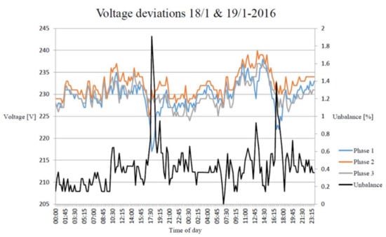
Figure 1.
Voltage unbalance (black) in a secondary substation in Denmark (courtesy of Thy Mors Energi A/S).
More recently, a power outage of about 6 h on the Christmas Eve of 2021 was affecting 335 customers in the city of Fredericia, Denmark [5]. Preliminary investigations are pointing to a very high electrical consumption due to EV chargers and heat pumps combined with an uneven phase distribution of the customers’ loads in the supply system. The occurrence of these events may further increase in the near future due to higher penetration of distributed resources.
Another challenge of modern distribution grids is related to the high harmonic content generated by, e.g., switch mode power supplies, renewable generation, asynchronous motors-based loads, etc. A typical voltage harmonic content in a low-voltage grid is shown in Figure 2. The measurements were performed in a 10/0.4 kV substation supplying a pig farm. A 250 kW solar PV system, mounted on the stable, and a 255 kW asynchronous generator-based wind turbine were connected on the secondary side of the transformer. A relatively high level of the fifth and seventh harmonics was given by the many induction motors driving different installations on the pig farm. The harmonic compatibility levels and the Total Harmonic Distortion (THD) still complied with the EN 50160 standard.
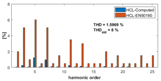
Figure 2.
Voltage harmonic compatibility levels (HCL) for a substation supplying a pig farm with local renewable generation on-site, i.e., solar PV and wind turbines.
Reliability and security of the power supply is essential in modern society and the national network codes are one of the instruments for assuring them. Typically, the basic requirements for the grid connection of units connected to distribution grids cover the power quality aspects, frequency response, and protective functions such as over/under voltage and frequency, e.g., [6,7,8,9]. Large facilities above 1 MW may be required to provide additional control functions such as voltage and frequency control, e.g., [6,7,8,9]. Specific requirements for the measurement accuracy of voltage and frequency are also specified. Typically, the Root-Mean-Square values of the voltage in every phase should be calculated according to [10,11]. Frequency measurements must be carried out with 10 mHz accuracy or higher, covering at least an interval from 47 to 52 or 53 Hz [6,7,8,9]. The sensitivity of the control function must be 10 mHz or lower [6,7,8,9].
Modern distributed energy resources up to 500 kW typically use a two-level Active Front End voltage source inverter directly connected to a low-voltage utility grid, e.g., [12,13,14,15,16,17]. The switching frequency is 2.5 to 8 kHz, depending on the cooling method of semiconductors [12,13,14,15,16,17]. Typically, synchronous reference frame-based algorithms are employed to achieve the decoupled control of active and reactive power at the point of connection (PoC) [18,19]. These algorithms rely on an accurate estimation of the voltage angle at the PoC for a wide range of operational conditions, i.e., harmonics, phase jumps due to short circuits, large voltages, and frequency excursions.
Thus, grid synchronization and the monitoring of grid variables, i.e., voltages and frequency, have received a lot of attention over the last decade with many algorithms and approaches proposed, e.g., [18,19,20,21,22,23,24,25,26,27,28,29,30,31,32], to mention some of the previous work undertaken in this area. It is also recognized by the research community that there is no unique solution that can offer high accuracy, fast dynamics, robustness, and low computational burden for every grid condition.
Two main approaches are typically used for grid synchronization, i.e., open loop and closed loop. The first approach estimates the grid voltage angle only based on filtered phase voltages measured at the PoC, while the second approach may include a filtering stage but will track the accuracy of estimation by using a closed-loop control structure. It is well recognized that open-loop methods lack accuracy, have slow-phase tracking dynamics, and are also prone to interference, especially under highly distorted voltages. The synchronous reference frame phase-locked-loop (SRF-PLL) is one of the most utilized closed-loop structures for grid synchronization [19,20,21,22,23,24,25,26,27,28,29,30,31,32]. It offers fast dynamics and a low steady-state error for grid voltages with low harmonic content [32]. This structure has been used as a benchmark for assessing newly proposed approaches for grid synchronization in the last few years. The tuning methodology for SRF-PLL is based on designing the response of the closed-loop system to match the desired response of a second-order system where the settling time and damping are the design parameters [19]. An overview of the selected relevant approaches for grid monitoring and synchronization is provided in the next paragraph.
A hybrid PLL for interconnecting renewable energy systems to the grid is proposed in [24]. This structure aims to track accurately the grid voltage angle under fault conditions, i.e., two-phase to ground faults and voltage sags down to 50% from the nominal voltage. Simulation results against SRF-PLL and other synchronization methods, as well as a laboratory implementation on a dSPACE platform, are provided [24]. However, the steady-state accuracy in estimating grid frequency under faulty conditions and high harmonic content is not documented. Moreover, the RMS voltages in every phase cannot be calculated in the proposed PLL structure. Considerations about discretization methods are not provided either.
A comprehensive design methodology for SRF-PLL structures, i.e., multiple reference frame PLL (MRF-PLL), dual second-order generalized integrator PLL (DSOGI-PLL), and multiple complex coefficient filter PLL (MCCF-PLL), is proposed in [23]. The authors propose a combination of low-pass and notch filters inserted in the SRF-PLL loop combined with positive sequence extraction in the case of MRF-PLL. The tuning of these filters is performed for a cut-off frequency twice that of the fundamental one, while the classical tuning for the PLL is still used. This approach does not allow the desired settling time to be specified. A similar tuning approach is used for MCCF-PLL. The performance of the proposed design was evaluated on a DSP implementation under various grid events, e.g., voltage sags, phase jumps, voltage unbalances, and harmonics. Targeted harmonics, i.e., the fifth and the seventh, are removed from the stationary reference frame voltages using multiple filters in the case of MCCF-PLL. This leads to a relatively complicated implementation when targeting the entire spectra up to the 40th harmonic. The authors claim that MCCF-PLL provides a zero steady-state error in estimating grid frequency when the fifth and the seventh harmonics are present in the three-phase supply voltages. However, the laboratory results do not consider the entire harmonic spectra as defined in power quality standards, e.g., EN 50160 [10]. Moreover, practical considerations regarding discretization methods for all the proposed filters are not provided.
A moving average filter (MAF) instead of a low-pass filter is introduced before the PI controller in the SRF-PLL in [25]. A 10 ms window length is considered for the MAF and a 20 ms one is proposed for grid voltages with dc-offset and harmonics. Two controllers, i.e., a PI and a PID controller, are considered in the PLL structure. The performance of these two structures is evaluated using offline simulation results where Gaussian noise is added. Harmonic content according to power quality standards is not considered. Considerations about discretization methods and practical implementation are not provided.
A sliding Discrete Fourier Transform is proposed in [26] for harmonic filtering of the stationary reference frame voltage components (αβ) as an equivalent to MAF in the synchronous reference frame. A Proportional (P) controller is considered in the proposed PLL structure and guidelines for the gain selection are provided. The performance of the proposed approach is evaluated by means of offline simulations and laboratory implementation on a dSPACE platform under voltage/frequency steps, phase jumps, and harmonics. The approach proposed in [26] does not provide an estimation of voltage amplitude in each phase, and the steady-state error in estimating grid frequency is not quantified.
A robust open-loop estimation of grid frequency based on the Clarke transform and fixed transport delay finite impulse response filters is proposed in [29]. It provides only an estimation of grid frequency and, thus, cannot be used for the grid synchronization of converter control.
A new method for the estimation of grid frequency using a Low-Pass Filter (LPF) approach is provided in [27]. The estimated frequency is used to tune a second-order generalized integrator (SOGI) filter. The proposed approach presents a smooth transient response to steps in grid frequency and good rejection of harmonic distortions. However, the verification is based only on simulation results and no practical laboratory implementation is provided.
A novel open-loop algorithm of resonant frequency estimation using a resonant filter and a signal scaling model is proposed in [30]. Its performance is compared with the double decoupled synchronous reference frame PLL (DDSRF-PLL) and DSOGI-PLL. The algorithm provides only the estimated grid frequency, and thus it cannot be used for grid synchronization.
Finally, a more recent paper evaluated several DSOGI-PLL algorithms proposed over the last decade for phase estimation in weak grids, against the classical SRF-PLL [32]. The evaluation comprises extensive off-line simulation results, then laboratory testing for selected algorithms under a wide range of operational conditions including high harmonic content. Based on the results, it is concluded that fixed frequency double SOGI PLL (FFDSOGI-PLL) is the most suitable algorithm for weak grids with high harmonic content. It provides an accurate phase and frequency estimation when the grid frequency variations are within ±5%.
Based on the reviewed approaches [20,21,22,23,24,25,26,27,28,29,30,31,32], it was found that (i) the estimation of voltage magnitude in every phase is not considered at all; (ii) a clear tuning methodology of parameters in PLL-based algorithms that enable selection of the settling time is not presented; (iii) the quantification of both steady-state errors or deviations for phase and frequency estimations is not documented in all cases; and (iv) discretization methods and practical considerations for the implementation of the proposed algorithms are not provided.
This paper proposes a modified SRF-PLL structure including the tuning methodology for the parameters, which provides a robust and accurate estimation of the phase and frequency under a wide range of grid conditions, e.g., amplitude, frequency, and phase steps as well as high harmonic content. It also provides the estimation of the voltage magnitude in every phase. Practical considerations are also given for the discretization and implementation of low-cost commercial DSPs. The algorithm is suitable for synchronization and monitoring in smart grid applications, e.g., protective functions, frequency response, and frequency control. The proposed approach is verified through laboratory experiments against the FFDSOGI-PLL, which is the state-of-the-art algorithm for these applications [32].
Section 2 presents the grid monitoring and synchronization algorithms in scope, i.e., FFDSOGI-PLL and the proposed one. Block diagrams and detailed tuning methodologies are given. Section 3 discusses the practical implementation of the algorithms in microcontrollers. A sensitivity analysis of discretization methods applied for the main subsystems in the algorithm is performed in terms of frequency response. Section 4 presents the experimental results. Finally, discussions and recommendations are detailed in Section 5.
2. Grid Monitoring and Synchronization Algorithms
This section will first give a brief overview of the FFDSOGI-PLL algorithm as the most suitable synchronization algorithm for low-voltage grids with high harmonic content and unbalances according to [32]. Then, the proposed PLL algorithm will be detailed in terms of main computational modules and tuning methodology, as well as a sensitivity analysis for parameters.
2.1. FFDSOGI-PLL
2.1.1. Block Diagram
The general structure of the FFDSOGI-PLL is shown in Figure 3. The three-phase voltages are transformed to a stationary reference frame (αβ) and then applied to a DSOGI-based positive sequence extraction (DSOGI-PSE). The positive sequence values in the stationary reference frame are then transformed to a synchronous reference frame by Clarke transform using the estimated grid voltage angle. The quadrature component of the synchronous reference frame voltage (vq) is then applied to the SRF-PLL that provides the estimated grid voltage angle and the grid frequency. Typically, the positive sequence voltage in the stationary reference frame is used to compute the RMS voltage of the three-phase system. An LPF with a cut-off frequency of 10 Hz then provides the final estimated voltage value.
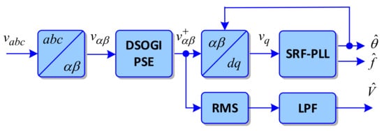
Figure 3.
Block diagram of FFDSOGI-PLL (based on [30]).
The structure of the DSOGI-PSE block is detailed in Figure 4 where the DSOGI quadrature signal generators (DSOGI-QSG) extract the direct and quadrature signals of the stationary reference frame voltages.
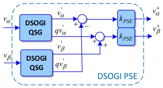
Figure 4.
Block diagram of DSOGI-based Positive Sequence Extraction.
These DSOGI-QSG blocks implement the following transfer functions [32]:
where k is the quality factor and ω is the centered frequency. Typically, the quality factor is with a centered frequency of 50 Hz for these two filters. A value of 0.5 is used for the kPSE gain in Figure 4. The Bode plots for these two filters are shown in Figure 5.
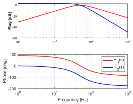
Figure 5.
Frequency response of SOGI-QSG transfer functions for direct and quadrature axis.
The transfer function for d-axis is basically a band pass filter centered on 50 Hz while the one in q-axis is a second-order low-pass filter with a gain bigger than unity for frequencies up to cut-off frequency, i.e., 50 Hz.
Finally, the structure of the SRF-PLL block is given in Figure 6 with a PI controller that basically tracks the angle of the grid voltage. The estimated grid frequency is also filtered with an LPF with a cut-off frequency of 10 Hz.
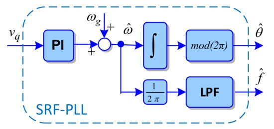
Figure 6.
Block diagram of SRF-PLL.
2.1.2. SRF-PLL Design
The tuning of the PI controller and, hence, the overall performance of the PLL is based on designing the response of the closed-loop system to match the desired response of a second-order system [19]. The settling time and damping are the design parameters for this tuning [19]. The linearized small-signal model of the entire SRF-PLL is given in Figure 7, based on [17].

Figure 7.
Small-signal model for SRF-PLL based on [19].
Where the following transfer function is considered for the PI controller:
The transfer function between the error signal ε fed to the PI controller and the estimated voltage angle shall be equivalent to a second-order system as:
The parameters of the PI controller are then obtained as:
The design typically assumes a desired damping factor and a settling time within a specified steady-state bandwidth error. Based on these values the natural frequency is computed as:
where is the steady-state error gain, as defined in Table 1.

Table 1.
Typical values for steady-state error gain .
In general, a damping factor of 0.707, a settling time of 100 ms, and a 1% steady-state error criterion are used as inputs for the PLL design. Thus, by using these design inputs the PLL parameters are obtained as and .
2.2. Proposed PLL
This section presents the proposed PLL structure.
2.2.1. Block Diagram
The block diagram of the proposed PLL is shown in Figure 8.

Figure 8.
Block diagram of proposed PLL structure for grid monitoring and synchronization.
The three-phase grid voltages from the Point of Connection (PoC) are filtered using a band pass filter (BPF) then the common mode voltage (or the zero-sequence component) is extracted using the common mode voltage extraction (CMVE) block. Based on the filtered voltages , the stationary reference frame components and then the q-axis component are calculated using , the estimated angle of the grid voltage. Besides the Park transformations, a weighting of voltages is applied so that the synchronous reference frame components are provided per unit. The quadrature component of the grid voltage is then filtered with an LPF and applied to the PI controller as in the SRF-PLL structure. Typically, the error signal fed in the PI block has a 100 Hz component due to voltage unbalances, i.e., the negative sequence component in the supply voltages. This component passes through the PI controller and then is integrated when estimating the grid frequency. Thus, the main purpose of the LPF filter is to remove the 100 Hz component that may appear on the q-axis component used for tracking the angle. This structure also provides the root-mean-square values of voltages in each phase. Instead of an LPF as in typical PLL structures, a circular buffer is used to calculate the mean value over the desired time window. The same circular buffer is also used to calculate the mean value of the estimated grid frequency .
The following subsections will detail the design of the main subsystems in this block diagram including the tuning procedure for the PI.
2.2.2. Band Pass Filter Design
The band pass filter is described by the following transfer function in the Laplace domain:
The centered frequency of the filter is 50 Hz in this case, while the quality factor Q is given by where BW is the filter bandwidth, being the main design parameter. Selection of the BW is essential for filtering polluted grid voltages without affecting their magnitude and phase. The BPF should also have the desired performance for grid frequency excursions as required in network codes, i.e., 47 to 53 Hz. It may be useful to utilize a narrow bandwidth to better filter harmonic components; however, a large phase delay may be introduced as well as a decrease in the measured voltage amplitude. A sensitivity analysis of the BPF for different BW values is shown in Figure 9.
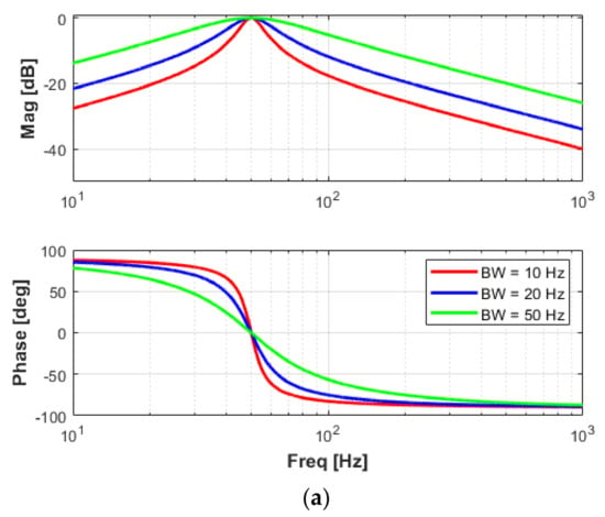
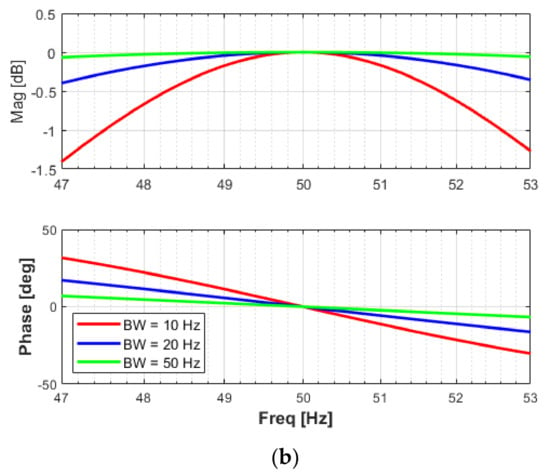
Figure 9.
Frequency response of the BPF for different BW values: (a) extended frequency range; (b) required operational frequency range by network codes.
Narrow filter bandwidth values significantly attenuate the input voltages and also introduce phase delays of about 30 degrees at the frequency interval limits, i.e., 47 Hz and 53 Hz, as shown in Figure 9b. Thus, for grid-connected applications, a BW value of 50 Hz will provide a good rejection of harmonic components without attenuating the amplitude of the measured voltages and their phase.
2.2.3. Common Mode Voltage Extraction
The common mode voltage or zero sequence component may have significant values in the case of power converters connected to four-wire unbalanced low-voltage distribution grids. Voltage measurements from a secondary substation are shown in Figure 1. A voltage unbalance of about 2% was reported for RMS voltage amplitudes, i.e., 216, 230, and 235 volts, in the three phases. This gives a magnitude for the zero sequence of about 44 V. By removing this off-set from the measured three-phase voltages, it will improve both the estimation of RMS voltages per phase and the performance of the PLL.
Thus, the CMVE block implements the following equation:
2.2.4. Mean Value Computation
A circular buffer is used to store values over the desired time window for the computation of RMS values for voltages and frequency. The size of the buffer shall be determined based on the sampling time for running the PLL and the desired time window. The RMS voltages for monitoring and protective functions shall be provided every 10 ms. Estimated frequency may be computed in 2 stages. A 10 ms average may be useful for fast controls, e.g., frequency containment reserves or frequency response, while a 200 ms value may be used for monitoring purposes. Thus, 50 values per buffer are needed for averaging the input over 10 ms with a sampling frequency of 5 kHz.
2.2.5. PI Tuning Procedure
The small-signal model for tuning the proposed PLL structure will include the additional LPF in the main path as shown in Figure 10.

Figure 10.
Small-signal model of proposed PLL structure.
The transfer function for the low-pass filter is formulated in terms of time response as:
where is the cut-off frequency of the filter.
Additionally, a time constant Tint of 1 s is included for the integrator to support the design process.
The symmetry optimum criterion as detailed in [33] is proposed for determining the parameters of the PI controller in this case. This criterion offers the “best” response for the closed loop system with dB gain near zero over a wide range of frequencies and a good rejection of disturbances [34]. The method is also suitable for systems having a pure integrator [34] as in the case of the proposed PLL structure. According to the design methodology explained in [34], the “optimum” parameters for the PI controller to provide the “best” response for the closed-loop system are determined as:
The main assumption here is that the time response of the LPF is considerably smaller than the time constant of the integrator. The method also provides analytical expressions to estimate time response (), settling time (), and overshoot (OS) for a step response as:
Thus, the time constant of the LPF may be the main design parameter for this tuning procedure. A sensitivity analysis for three values of the cut-off frequency of LPF, i.e., 10, 20, and 50 Hz, is performed using the small-signal model. The frequency response of the closed-loop system is presented in Figure 11 while the step response is shown in Figure 12. The magnitude is slightly amplified around the cut-off frequency. The time response and, hence, the settling time increase when the cut-off frequency decreases. Thus, the cut-off frequency of the LPF defines the response and settling times for the closed-loop system.
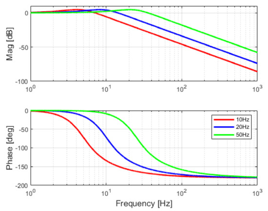
Figure 11.
Frequency response of proposed PLL linearized model.
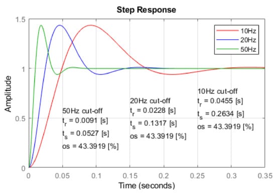
Figure 12.
Step response of proposed PLL structure for different cut-off frequencies of LPF.
An evaluation of the deviations from the analytical expressions of the expected performance and the actual estimations provided by MATLAB® based on step response is given in Table 2. Overall, the analytical expressions quantify very well the expected response of the closed-loop system.

Table 2.
Dynamic performance of closed loop system for LPF cut-off frequency of 20 Hz.
The design can also start from a defined time response for the closed system and calculate the required cut-off frequency of the LPF using Equation (12).
3. Considerations for Practical Implementation in Microcontrollers
3.1. Discretization Methods
In order to implement any control algorithm on a microcontroller, an analog system in the S-domain needs to be transformed into a digital system in the Z-domain. The discrete-time equivalent equations can be derived by different approximation methods, e.g., the Forward Euler, Backward Euler, and Trapezoidal (Tustin) methods. However, the stability of these approximations needs to be considered for a practical implementation. A stable continuous-time system may be mapped into an unstable discrete-time system when using Forward Euler, while Backward Euler will always give a stable discrete-time system. The main advantage of using Tustin’s approximation is that the left half s-plane is transformed into the unity circle in the z-plane [34,35]. These methods are also available in MATLAB®/Control System Toolbox, which makes the transformations easier. Automatic code generation is supported by many hardware platforms [36]. However, this feature is not always supported, and the algorithms need to be directly coded. A simple and consistent way to cover the implementation of the algorithm in any hardware platform is presented in the following.
The methodology will consider, as an example, a simple second-order system such as the q-axis SOGI-QSG given by (2):
According to the discretization method, the Laplace operator s is replaced by an expression for translation to Z-domain, as given in Table 3.

Table 3.
Translation of Laplace operator to Z-Domain.
By performing algebraic calculations, the discrete transfer function can be expressed in the causal canonical form as:
From this expression, a basic block diagram for implementation can be realized, as shown in Figure 13.
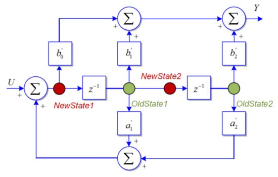
Figure 13.
Block diagram implementation of a second-order system.
Starting from this block diagram, the pseudocode for the considered transfer function is shown in Box 1.
The variables OldState1 and OldState2 shall be defined as persistent. This procedure can be applied to all transfer functions presented in Section 2 and it provides a consistent way to implement any transfer function in various simulation environments. Moreover, it provides the opportunity to analyze complex control models using control theory tools such as frequency domain analysis, root locus, etc. The next subsections will give a sensitivity analysis of different discretization methods for the transfer functions presented in Section 2.
Box 1. Pseudocode implementation of a second-order system.
%Calculation of New State variable
NewState1 = U + a1 * OldState1 + a2 * OldState2;
NewState2 = OldState1;
%calculation of Output
Y = b0 * NewState1 + b1 * OldState1 + b2 * OldState2;
%Update Old State variable for next run
OldState1 = NewState1;
OldState2 = NewState2;
3.2. Sensitivity Analysis for FFDSOGI
The transfer functions for DSOGI and QSOGI QSG were discretized using the Backward Euler method, as the most common method preferred by industry, and the Tustin one, as it can provide a stable system at the cost of computational time [37]. A sampling frequency of 5 kHz is used for discretization. The frequency responses for both functions are presented in Figure 14. A resonance frequency at half sampling frequency, i.e., 2.5 kHz, appears as expected when the Tustin method is used. The magnitude response for QSOGI QSG is higher than the continuous S-Domain or Backward Euler implementation at the cut-off frequency. The phase response is also changed around the cut-off frequency when using Tustin implementation for the QSOGI QSG. Overall, Backward Euler gives a good response compared to the S-Domain reference response for both magnitude and phase for a frequency range covering DC signals to about twice the cut-off frequency. Greater harmonic content in the input signals, as expected in distorted distribution grids, may affect the response of both transfer functions and, hence, the entire monitoring and synchronization process.
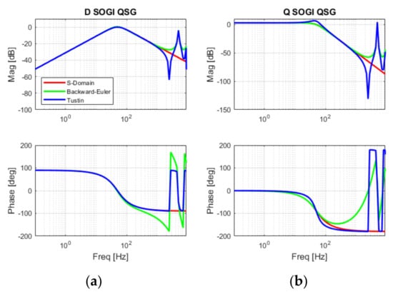
Figure 14.
Frequency response with different discretization methods: (a) DSOGI-QSG and (b) QSOGI-QSG.
The same discretization methods were applied to the SRF-PLL structure that comprises PI and the Integrator, as shown in Figure 6. Several combinations of methods were investigated as previously reported work highlighted the instability challenges for practical implementation [38].
All considered discretization methods show a similar magnitude response for frequencies up to 1 kHz as shown in Figure 15. However, the phase response is very different in the frequency interval from 100 to 1000 Hz. Utilization of the Tustin method for discretization of the PI controller leads to a nonminimum-phase system that will exhibit a slow response due to the faulty behavior at the start of the response [39]. Thus, an implementation using Discretization #1 or #2 is preferred.
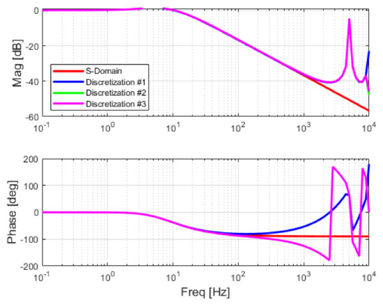
Figure 15.
Frequency response of SRF-PLL with different discretization methods: Discretization #1: Backward Euler for both PI and Integrator; Discretization #2: Backward Euler for PI and Forward Euler for Integrator and Discretization #3: Tustin for PI and Forward Euler for Integrator.
3.3. Sensitivity Analysis for Proposed PLL
The sensitivity analysis for the proposed PLL structure was performed individually for the main components since the band pass filter does not affect the overall response in tracking the voltage angle. Again, the main components, namely, the BPF and PLL main loop, were discretized using the Backward Euler method, and the Tustin one, which was the same as that for the FFDSOGI, for a suitable comparison. Forward Euler is also considered for the integrator in the main PLL loop as a solution to remove instabilities [38].
3.3.1. Band Pass Filter
The frequency response of the BPF using the two discretization methods is shown in Figure 16. The magnitude response is highly overestimated around the centered frequency, i.e., 50 Hz, when using the Backward Euler method, while the Tustin method exhibits a similar response as the S-Domain transfer function. Similarly, the Backward Euler implementation adds an additional phase delay in the response compared to the other two cases. The implementation using the Tustin method provides the expected attenuation as well as phase delay over the entire frequency interval of interest, i.e., 0.1 to 1000 Hz. The upper-frequency limit can be extended only by increasing the sampling frequency.
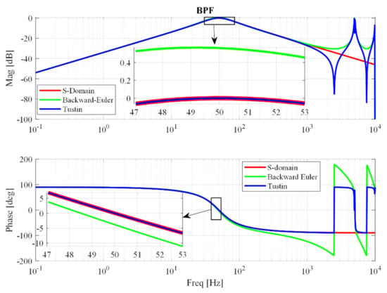
Figure 16.
Frequency response of BPF with different discretization methods.
3.3.2. PLL Main Loop
The discretization of the PLL main loop considers three combinations of methods, as in the previous analysis, and the frequency response of the PLL main loop is shown in Figure 17.
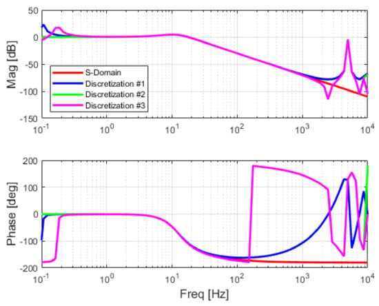
Figure 17.
Frequency response of the PLL main loop with different discretization methods: Discretization #1: Backward Euler for LFP, PI, and Integrator; Discretization #2: Tustin for LPF, Backward Euler for PI and Forward Euler for Integrator and Discretization #3: Tustin for LPF, Tustin for PI and Forward Euler for Integrator.
Discretization #1 and #3 exhibit resonances below 0.2 Hz, i.e., 0.1 Hz for Discretization #1 and close to 0.2 Hz for Discretization #3. This may be a disadvantage if low-frequency voltage oscillations are present in the power system. However, the inclusion of BPFs on input voltages completely mitigates any potential stability issues. All methods provide a similar magnitude response for frequencies above 0.5 Hz and up to 1 kHz. A shift of 180 degrees in the phase response is present for Discretization #1 and #3 at the same frequencies as the peaks in magnitude response (i.e., 0.1 Hz and 0.2 Hz) while there are no changes in the phase response for Discretization #2. Overall, Discretization #2 provides a very good response in both magnitude and phase for a frequency range from 0.1 up to 100 Hz. Thus, this combination will be considered for further analysis and implementation in the laboratory setup.
3.4. MVC Implementation
As mentioned in Section 2.2.4, a circular buffer is used to store values over the desired time window for the computation of RMS values and frequency for the measured voltages. These RMS values are computed continuously at each sampling time, considering the entire length of the buffer, and down-sampled to the desired update rate, e.g., 10 or 200 ms.
4. Experimental Validation
4.1. Setup Description
The experimental setup for assessment of the two algorithms is presented in Figure 18. It consists of a grid simulator and a power electronic converter including an LC filter and an interface card for connection to a dSPACE DS1103 platform. Voltage measurements are provided by an LEM-based system. The grid simulator, a Regatron TC.GSS 50 kVA four quadrant system, is used to generate the voltage waveforms including a 2% unbalance with harmonic components according to EN 50160. The PLL algorithms are implemented in dSPACE, as explained in Section 3. Three tests (10% voltage dip, 0.5 Hz frequency drop, and a −60° phase jump) are performed to compare the performance between FFDSOGI-PLL and the proposed PLL structure. The voltage dip, large frequency excursion, and phase jump are scheduled in a sequential manner, in order to test the robustness of the considered PLL algorithms.
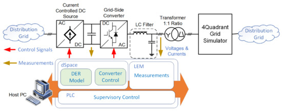
Figure 18.
Block diagram of experimental setup.
4.2. Experimental Results
4.2.1. Voltage Dip
The phase angle and frequency estimation from both FFDSOGI-PLL and the proposed PLL are compared in Figure 19 for a 10% drop in the supply voltages. The RMS values for all three voltages are shown for a clear illustration of the event. Both PLLs can track the grid angle for this event with similar performance. However, the main difference between them can be observed in the estimated frequency. The inclusion of CMVE and BPF blocks in the proposed PLL structure will provide fewer oscillations and also a lower overshoot for the proposed PLL compared to FFDSOGI-PLL. Meanwhile, the high 100 Hz ripple in the frequency estimation of FFDSOGI-PLL is given by the unbalanced three-phase voltage that cannot be removed. The proposed PLL has a first overshoot of about 33 mHz, while the FFDSOGI-PLL exhibits a first undershoot close to 900 mHz. Both algorithms have similar settling times close to the expected values from the design of about 150 ms.
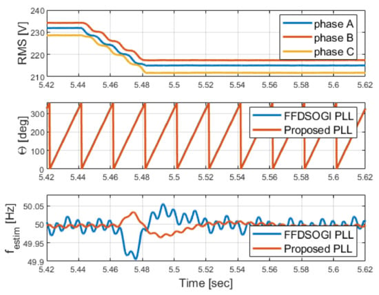
Figure 19.
Experimental results for 10% voltage dip.
4.2.2. Frequency Excursion
According to [40], the maximum rate of change of frequency (ROCOF) in the European continental grid is ±2.5 Hz/s. Therefore, a frequency ramp test is conducted as shown in Figure 20. As this event cannot be seen clearly in grid voltage waveforms, only the estimated grid voltage angle and frequency are shown in this figure.
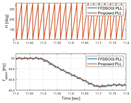
Figure 20.
Experimental results for a large frequency excursion.
Both the FFD-SOGI PLL and the proposed PLL can estimate the grid frequency excursion with accuracy. However, the background harmonics and voltage unbalances generate a high ripple of about ±20 mHz in the frequency estimation for FFDSOGI-PLL. On the other hand, the proposed PLL has a better rejection of the harmonic content and unbalanced voltage measurement signals and provides better performance for grid frequency estimation with a ripple of less than ±5 mHz.
4.2.3. Phase Jumps
Remote short circuits in distribution grids are typically observed at the point of connection of a grid-connected converter as a phase jump in the grid voltage, assuming that the protection systems are reacting as designed. Thus, a test case with a 60-degree phase jump is considered as shown in Figure 21.
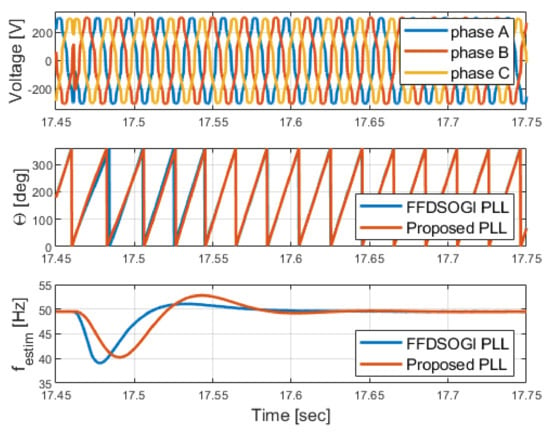
Figure 21.
Experimental results for a 60-degree phase jump in the supply voltages.
The estimated frequency from FFDSOGI-PLL has the first undershoot of 39 Hz, while the proposed PLL has an undershoot of 40.3 Hz. Both, algorithms provide a similar estimation of the grid angle of about 150 ms after the event. Due to the BPF used on measured voltages, the phase jump and high-frequency noise are filtered out by the proposed PLL structure. On the other hand, the FFDSOGI-PLL also provides a good estimation of grid frequency as the DSOGI-PSE block acts as a band pass filter with a 50 Hz center frequency. Therefore, both PLLs have a similar capability to reject large phase jump disturbances.
4.2.4. Steady State Operation
The grid connection requirements specify a ±10 mHz accuracy for measurement of the grid frequency [6,7,8]. The performance of both PLLs for estimating the nominal grid frequency of 50 Hz is shown in Figure 22.
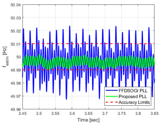
Figure 22.
Experimental results for frequency estimation in normal operation.
The FFDSOGI-PLL exceeds the accuracy limits with at least 20 mHz while the proposed PLL structure provides the estimation inside the accuracy limits with an average ripple of ±4 mHz. The Grid Simulator has a static accuracy for a delivered frequency of 2 mHz [41], which can justify an average offset for both estimations.
4.3. Summary
In order to validate the theoretical analysis of the proposed PLL structure, three different dynamic test responses and a steady-state one are conducted. The proposed PLL algorithm is compared with the FFDSOGI-PLL under three test cases, i.e., a 10% voltage dip, a large frequency excursion, and a 60° phase angle jump, for a 2% unbalanced voltage supply system with a harmonic content according to EN 50160.
Both algorithms track the voltage phase angle in less than 150 ms as expected from the design and make them suitable for classical converter control schemes in a synchronous reference frame. The major difference between the two investigated algorithms is the quality of frequency estimation. The FFDSOGI-PLL has a high ripple of more than ±20 mHz in all tested grid events, which makes it non-compliant with the requirements for measurement accuracy from grid codes and standards. On the other hand, the proposed PLL provides a ripple of less than ±5 mHz in all investigated grid events.
5. Conclusions
The PLL algorithms including grid frequency estimation are critically important for grid-connected renewable energy sources and storage systems (i.e., wind turbines, PV plants, and battery systems). Moreover, new types of power electronics-based loads such as electrolyzers or EV charging points/stations are rapidly emerging in distribution grids. Thus, the application-oriented design of PLL is crucial for the operation of future distribution grids with high penetration levels of converter-based applications. A good synchronization, i.e., the accurate tracking of the grid voltage angle, will enable standard converter controls to be utilized in a wide range of grid conditions. The accurate estimation of grid frequency is also crucial for ancillary services such as fast frequency response and frequency containment reserves that must be implemented locally in the converter control.
In this paper, a robust PLL for grid synchronization and the frequency monitoring method is proposed and experimentally verified. A comparison with a state-of-the-art PLL algorithm based on FFDSOGI under different grid events, i.e., voltage dips, large frequency excursions, and phase jumps, is presented. A complete design procedure, sensitivity analysis, and guidelines for implementation in microcontrollers are also provided. The impact of the different discretization methods and parameters is also theoretically analyzed. We identified that the discretization methods for every subsystem in both algorithms are very important and should not be overlooked. Both PLL algorithms have a specific combination for these discretization methods for achieving the desired stable response over the required frequency range. The complexity and number of states are similar for both algorithms and should not pose major challenges for implementation in any low-cost microcontrollers. The experimental verification in a laboratory setup revealed that both algorithms track the voltage angle under the considered grid events with similar performance as expected from the design phase. However, the FFDSOGI-PLL is not able to estimate the grid frequency with the required accuracy according to the grid codes, i.e., less than ±10 mHz. On the other hand, the proposed PLL estimates the grid frequency for all considered grid events, with an accuracy of less than ±5 mHz. Future work on the proposed PLL algorithm may include an assessment of asymmetrical grid faults in distribution grids.
Author Contributions
Conceptualization, F.I.; methodology, F.I.; validation, W.Z. and T.K.; formal analysis, F.I. and T.K.; writing—original draft preparation, F.I.; writing—review and editing, F.I., W.Z. and T.K.; funding acquisition, F.I. All authors have read and agreed to the published version of the manuscript.
Funding
The authors acknowledge the financial support from EU-REACTRF-21-0026 “Center of Green Energy and Cross-Sector Coupling” and “PtX Converter” projects.
Data Availability Statement
The data from laboratory measurements are available on request.
Conflicts of Interest
The authors declare no conflict of interest.
References
- REN21. Renewables 2021 Global Status Report; REN21 Secretariat: Paris, France, 2021; ISBN 9783948393038. Available online: https://www.ren21.net/reports/global-status-report/ (accessed on 17 February 2022).
- Available online: https://ec.europa.eu/eurostat/statistics-explained/index.php?title=Renewable_energy_statistics#Wind_and_water_provide_most_renewable_electricity.3B_solar_is_the_fastest-growing_energy_source (accessed on 17 February 2022).
- IEA. Global EV Outlook 2022; License: CC BY 4.0; IEA: Paris, France, 2022; Available online: https://www.iea.org/reports/global-ev-outlook-2022 (accessed on 17 February 2022).
- IEA. The Future of Hydrogen; License: CC BY 4.0; IEA: Paris, France, 2019; Available online: https://www.iea.org/reports/the-future-of-hydrogen (accessed on 17 February 2022).
- TV2 News. Available online: https://nyheder.tv2.dk/lokalt/2021-12-25-hundredvis-af-huse-uden-stroem-hele-juleaften-familie-spiste-sig-maet-i#:~:text=I%20Fredericia%20havde%20flere%20hundrede%20mennesker%20ikke%20str%C3%B8m%20juleaften.&text=%C3%85rsagen%20til%20str%C3%B8mafbrydelsen%20var%20if%C3%B8lge,resulterede%20i%20en%20sprunget%20sikring (accessed on 17 February 2022).
- ENTSO-E. ENTSO-E Network Code for Requirements for Grid Connection Applicable to All Generators; ENTSO-E: Brussels, Belgium, 2012. [Google Scholar]
- Energinet. Technical Regulation 3.2.2 for PV Power Plants above 11 kW; Energinet: Erritsø, Denmark, 2016. [Google Scholar]
- Energinet. Technical Regulation 3.3.1 for Battery Plants; Energinet: Erritsø, Denmark, 2017. [Google Scholar]
- Dansk Energi. Technical Regulation for Grid Connection of Consumers to Utility Grid below 1 kV; Green Power Denmark: Copenhagen, Denmark, 2022. (In Danish) [Google Scholar]
- DS/EN 50160:2010; Voltage Characteristics of Electricity Supplied by Public Electricity Networks. The Slovenian Institute for Standardization: Ljubljana, Slovenia, 2010.
- DS/EN 60038:2011; CENELEC Standard Voltages. The Slovenian Institute for Standardization: Ljubljana, Slovenia, 2011.
- Ingeteam. Available online: https://www.ingeteam.com/en-us/power-electronics/power-converters/pc28_6_171/ingedrive-lv200.aspx (accessed on 9 August 2023).
- ABB. Available online: https://new.abb.com/power-converters-inverters/wind-turbines/utility-scale/acs880/technical-data (accessed on 9 August 2023).
- Fronius Tauro. Available online: https://www.fronius.com/en/solar-energy/installers-partners/products-solutions/commercial-energy-solutions/tauro-commercial-solar-inverter-for-large-scale-pv-systems (accessed on 9 August 2023).
- Danfoss EC-C1200-450. Available online: https://www.danfoss.com/en/products/dps/electric-converters-and-machines/electric-converters-and-machines/electric-converters/#tab-overview (accessed on 9 August 2023).
- SMA Sunny Central Up. Available online: https://www.sma.de/en/products/solarinverters/sunny-central-2200-2475-2500-ev-2750-ev-3000-ev.html (accessed on 9 August 2023).
- SMA Sunny Central Storage. Available online: https://www.sma.de/en/products/battery-inverters/sunny-central-storage-1900-2200-2475-2900.html (accessed on 9 August 2023).
- Timbus, A. Grid Monitoring and Advanced Control of Distributed Power Generation Systems. Ph.D. Thesis, Institute of Energy Technology, Aalborg University, Aalborg, Denmark, 2007. [Google Scholar]
- Teodorescu, R.; Liserre, M.; Rodriguez, P. Grid Converters for Photovoltaic and Wind Power Systems; IEEE: Piscataway, NJ, USA; John Wiley and Sons Ltd.: Singapore, 2011; pp. 43–89. ISBN 9780470057513. [Google Scholar]
- Eren, S.; Karimi-Ghartemani, M.; Bakhshai, A. Enhancing the three-phase synchronous reference frame PLL to remove unbalance and harmonic errors. In Proceedings of the 35th Annual Conference of IEEE Industrial Electronics, Porto, Portugal, 3–5 November 2009; pp. 437–441. [Google Scholar] [CrossRef]
- Guo, X.; Wu, W.; Chen, Z. Multiple-Complex Coefficient-Filter-Based Phase-Locked Loop and Synchronization Technique for Three-Phase Grid-Interfaced Converters in Distributed Utility Networks. IEEE Trans. Ind. Electron. 2011, 58, 1194–1204. [Google Scholar] [CrossRef]
- Gonzalez-Espin, F.; Figueres, E.; Garcera, G. An Adaptive Synchronous-Reference-Frame Phase-Locked Loop for Power Quality Improvement in a Polluted Utility Grid. IEEE Trans. Ind. Electron. 2012, 59, 2718–2731. [Google Scholar] [CrossRef]
- Golestan, S.; Monfared, M.; Freijedo, F.D. Design-Oriented Study of Advanced Synchronous Reference Frame Phase-Locked Loops. IEEE Trans. Power Electron. 2013, 28, 765–778. [Google Scholar] [CrossRef]
- Hadjidemetriou, L.; Kyriakides, E.; Blaabjerg, F. A New Hybrid PLL for Interconnecting Renewable Energy Systems to the Grid. IEEE Trans. Ind. Appl. 2013, 49, 2709–2719. [Google Scholar] [CrossRef]
- Golestan, S.; Ramezani, M.; Guerrero, J.M.; Freijedo, F.D.; Monfared, M. Moving Average Filter Based Phase-Locked Loops: Performance Analysis and Design Guidelines. IEEE Trans. Power Electron. 2014, 29, 2750–2763. [Google Scholar] [CrossRef]
- Subramanian, C.; Kanagaraj, R. Rapid Tracking of Grid Variables Using Prefiltered Synchronous Reference Frame PLL. IEEE Trans. Instrum. Meas. 2015, 64, 1826–1836. [Google Scholar] [CrossRef]
- Matas, J.; Martin, H.; Elmariachet, J.; Abusorrah, A.; Al-Turki, Y. A new LPF-based grid frequency estimation for the SOGI filter with improved harmonic rejection. In Proceedings of the International Conference on Renewable Energies and Power Quality (ICREPQ’18), Salamanca, Spain, 21–23 March 2018. [Google Scholar]
- Zhao, J.; Zhan, L.; Yin, H.; Li, F.; Yao, W.; Liu, Y. Recent Development of Frequency Estimation Methods for Future Smart Grid. IEEE Open Access J. Power Energy 2020, 7, 354–365. [Google Scholar] [CrossRef]
- Reza, M.S.; Hossain, M.M.; Agelidis, V.G. A Method without Stability Issue for Robust Estimation of Three-Phase Grid Frequency. IEEE J. Emerg. Sel. Top. Ind. Electron. 2021, 3, 854–859. [Google Scholar] [CrossRef]
- Zielinski, D.; Fatyga, K. Frequency Estimation for Grid-Tied Inverters Using Resonant Frequency Estimator. Energies 2021, 14, 6513. [Google Scholar] [CrossRef]
- Chamorro, H.R.; Guel-Cortez, A.-J.; Africano, Y.; Jimenez, F.; Tonkoski, R.; Martinez, W. Grid frequency estimation based on extended kalman filter in connected AC microgrids. In Proceedings of the IEEE 30th International Symposium on Industrial Electronics (ISIE), Kyoto, Japan, 20–23 June 2021. [Google Scholar] [CrossRef]
- Pinto, J.; Carvalho, A.; Rocha, A.; Araújo, A. Comparison of DSOGI-Based PLL for Phase Estimation in Three-Phase Weak Grids. Electricity 2021, 2, 244–270. [Google Scholar] [CrossRef]
- Umland, J.W.; Safiuddin, M. Magnitude and symmetric optimum criterion for the design of linear control systems: What is it and how does it compare with the others? IEEE Trans. Ind. Appl. 1990, 26, 489–497. [Google Scholar] [CrossRef]
- Petersen, L.; Iov, F. Practical considerations regarding Implementation of wind power applications into real-time hardware-in-the-loop framework. In Proceedings of the NEIS Conference 2016: Sustainable Energy Supply and Energy Storage Systems (Nachhaltige Energieversorgung und Integration von Speichern), Hamburg, Germany, 15–16 September 2016; Schulz, D., Ed.; Springer: Cham, Switzerland, 2017; pp. 61–66. [Google Scholar]
- Levine, W.S. The Control Handbook; CRC Press: Boca Raton, FL, USA, 1996. [Google Scholar]
- Embedded Code Generation—MATLAB & Simulink Solutions, (n.d.). Available online: https://se.mathworks.com/solutions/embedded-code-generation.html (accessed on 29 November 2022).
- Ionel, D.M.; Blaabjerg, F. Renewable Energy Devices and Systems with Simulations in MATLAB® and ANSYS®; CRC Press: Boca Raton, FL, USA, 2020; ISBN 139780367656218. [Google Scholar]
- Ciobotaru, M. Reliable Grid Condition Detection and Control of Sigle-Phase Distributed Power Generation Systems. Ph.D. Dissertation, Aalborg University, Aalborg, Denmark, 2009. [Google Scholar]
- Ogata, K. Modern Control Engineering; Prentice Hall: Hoboken, NJ, USA, 2009; ISBN 0130432458. [Google Scholar]
- ENTSO-E. Rate of Change of Frequency (RoCoF) Withstand Capability; ENTSO-E: Brussels, Belgium, 2018. [Google Scholar]
- Regatron Datasheet TC.ACS.50.528.4WR.S.LC.; Regatron: Rorschach, Switzerland, 2020; Available online: https://www.regatron.com/assets/resources/Documents/Technical-Datasheets/TC.ACS/DS_TC.ACS.50.528.4WR.S.LC_EN_230414.pdf (accessed on 12 September 2023).
Disclaimer/Publisher’s Note: The statements, opinions and data contained in all publications are solely those of the individual author(s) and contributor(s) and not of MDPI and/or the editor(s). MDPI and/or the editor(s) disclaim responsibility for any injury to people or property resulting from any ideas, methods, instructions or products referred to in the content. |
© 2023 by the authors. Licensee MDPI, Basel, Switzerland. This article is an open access article distributed under the terms and conditions of the Creative Commons Attribution (CC BY) license (https://creativecommons.org/licenses/by/4.0/).