Article

Air Mass Flow and Pressure Optimization of a PEM Fuel Cell Hybrid System for a Forklift Application

1
Department of Thermal Machines, Faculty of Electrical Engineering, Mechanical Engineering and Naval Architecture, University of Split, R. Boškovića 32, 21000 Split, Croatia
2
Department of Thermodynamics, Faculty of Electrical Engineering, Mechanical Engineering and Naval Architecture, University of Split, R. Boškovića 32, 21000 Split, Croatia
3
HySA Systems Competence Centre, South African Institute for Advanced Materials Chemistry (SAIAMC), University of the Western Cape, Bellville 7535, South Africa
*
Author to whom correspondence should be addressed.
Energies 2024, 17(1), 120; https://doi.org/10.3390/en17010120
Submission received: 3 November 2023 / Revised: 15 December 2023 / Accepted: 18 December 2023 / Published: 25 December 2023
(This article belongs to the Section D2: Electrochem: Batteries, Fuel Cells, Capacitors)

Abstract

:
The air compressor holds paramount importance due to its significant energy consumption when compared to other Balance of Plant components of polymer electrolyte membrane (PEM) fuel cells. The air supply system, in turn, plays a critical role in ensuring the stable and efficient operation of the entire fuel cell system. To enhance system efficiency, the impact of varying the stoichiometric ratio of air and air pressure was observed. This investigation was carried out under real loading conditions, replicating the conditions experienced by the power module when fuel cells are in use within a forklift. The air compressor can be operated at different pressure and excess air ratios, which in turn influence both the fuel cell’s performance and the overall efficiency of the power module system. Our research focused on assessing the performance of PEM fuel cells under different load cycles, adhering to the VDI60 requirements for forklift applications. This comprehensive examination encompassed the system’s minimum and maximum load scenarios, with the primary goal of optimizing excess air and pressure ratio parameters, especially under dynamic load conditions. The results revealed that higher air pressures and lower excess air ratios were conducive to increasing system efficiency, shedding light on potential avenues for enhancing the performance of PEM fuel cell systems in forklift applications.

1. Introduction

Clean hydrogen has the potential to meet up to 24% of the world’s energy demand. As the global community, including the European Union, commits to reducing reliance on fossil fuels, hydrogen is emerging as a versatile solution for converting renewable energy from sources like wind and solar into storable forms. Most renewable energy sources are intermittent, opening spatial and temporal gaps between the availability of the energy and its consumption by end users [1]. To address these issues, it is necessary to develop suitable energy conversion or generating systems for the power grid. Hence, hydrogen can be used as a medium for energy conversion. Hydrogen can serve as a feedstock, fuel, energy carrier, and storage medium, offering numerous applications across industries, transportation, power generation, and construction [1]. In the realm of zero-emission vehicle technologies, there are two prominent developments: battery-powered electric vehicles using lithium-ion batteries exclusively, and fuel cell vehicles employing compressed hydrogen tanks and proton exchange membrane (PEM) fuel cells to generate electricity from hydrogen gas [2]. In the context of fuel cell assemblies, one crucial and energy-intensive component is the air compressor [3]. Generally, a higher airflow enhances the fuel cell voltage and efficiency [4], while lower mass flows can lead to operational challenges like the condensation of water and an insufficient oxygen supply [5]. The large-scale commercialization of PEMFCs requires higher current densities and power. The degradation of cell performance could appear at high operating current densities due to the massive accumulation of liquid water, which leads to flooding and impedes the gas diffusion [6]. In this case, water condensation is unfavorable, since it is more likely to worsen the tendency of flooding. However, if the generated water is very low and the membrane is going to dry, water condensation should be preferred. Proper water management is important to achieving a better fuel cell performance. High-velocity airflow is essential for removing water produced on the cathode side of the fuel cell, and it also increases the oxygen partial pressure, thereby boosting the fuel cell voltage [7]. However, extended operation at high airflow rates can lead to insufficient membrane moisture and potential drying issues [8]. The concept of the excess air ratio is vital, representing the ratio of actual airflow through the air compressor to the stoichiometric airflow required for complete oxygen consumption within the system [9]. Typical values range from 1.5 to 3.0, depending on system parameters and design considerations [10]. Furthermore, the pressure within the fuel cell system is influenced by the air compressor pressure ratio to the pressure drop across the fuel cell [11]. When using a throttle valve after the fuel cell assembly, it may lead to increased pressure resistance and cathode side pressure [12]. Alternatively, employing an expander (turbine) in place of a throttle valve allows for the utilization of the energy from the pressurized air mass flow, enhancing system efficiency [13]. The system of air supply is of utmost importance for ensuring the efficient and stable operation of the fuel cell system [14]. Proper air supply system operation aids in moisture removal, impacting humidity levels, while the oxygen content in the air directly affects the fuel cell voltage and efficiency. The compressor air can be supplied at various flow rates and pressures to the chimney, and these operational parameters, along with the corresponding compressor power consumption of the compressor, significantly influence system efficiency [15]. The maximum inlet air pressure in the fuel cell is constrained by the air compressor surging line [16], while the lowest pressure is determined by the pressure drop of the fuel cell and the air compressor’s choke. Operating points below the choke line and above the surging line has to be avoided to prevent compressor damage due to overheating and a high pressure [17]. The fuel cell power and efficiency are increased with a higher reactant pressure [18]. PEM fuel cells’ typical operating pressure is between 3 and 4 bar, and above 4 bar, there are mass transfer limitations [19]. One study has suggested that an operating pressure of 2 bar yields an optimal system efficiency, especially when using a screw compressor [20]. Another study utilized the Nernst equation to determine 2 bar as the optimum air pressure and 2 as the optimum excess ratio [21]. In another study [22], an 80 kW fuel cell vehicle was analyzed, and it was concluded that due to the modeled humidity inside the stack, affected by the excess air ratio and back pressure, the system power decreases as the regulating back pressure valve opens. At high loads, the system power increases when the back pressure valve opens. In study [23] it is shown that for 30 kW PEM fuel stack, the higher air pressures and lower air excess ratios increase the system efficiency at high loads. The maximum achieved system efficiency is 55.21% at the lowest continuous load point and 43.74% at the highest continuous load point. Furthermore, research into air mass flow and pressure optimization for PEM systems for fuel cell range extension found that various factors, such as the feed gas humidity, operating temperature, feed gas stoichiometry, air pressure, fuel cell size, and gas flow patterns, affect both steady-state and dynamic fuel cell responses [24]. For air pressures exceeding 1.8 bar(a), the fuel cell stack’s power gain due to pressurization is offset by the increased power required for air compression [25]. The optimization of super-high-speed electric air compressors for hydrogen fuel cell vehicles is a subject of investigation [26]. The positive influence of the air flow rate and air distribution inside a hydrogen fuel cell with a proton exchange membrane PEM on the performance characteristics was verified in research [27]. The authors conclude that for the long-term operation of the fuel cell at maximum power for a given voltage, it will be necessary to control the air flow depending on other parameters such as the air humidity and the temperature of the fuel cell. The influence of the operating parameters of the air pressure and excess air ratio on the dynamic response of stack voltage and on the net output power of a PEMFC system is analyzed. The optimal flow shows a tendency to be gradually larger as the current increases, and the optimal pressure to the output maximum net power was in a lower-value region [28]. In developing a computational model for PEMFCs mathematically, the calculation of the specific model parameters (activation losses, the electronic and ionic resistance, the oxygen concentration, and the current density) that are usually unknown is very important. The optimal parameter identification process of the fuel-cell model has been investigated using different recent optimization algorithms [29]. The durability and efficiency of PEM fuel cells depend on the temperature, and a typical operating temperature range is between 60 °C and 90 °C. A high temperature leads to membrane dehydration and a loss of conductivity, resulting in irreversible performance loss, and accelerates the degradation of the membrane of the PEM FC. In that case, severe ohmic polarization, a reduction in catalyst activity, and a rise in proton impedance due to the low temperature could appear [30]. This paper assesses the best PEM FC system efficiency at different load points. The optimization model for determining the working points of each parameter, aiming at the improvement of the efficiency of PEMFC system, is presented. The novelty in the work is a self-developed and verified model, as well as the research into the influence of the pressure and air flow on the system efficiency of an 11 kW power module with a PEM fuel cell designed for forklift applications. The study analyzes the relation between a higher oxygen partial pressure inside the stack (resulting in a higher efficiency) and the air compressor power consumption (leading to a lower efficiency) for two distinct load points during dynamical load operation. To achieve this, a power module with a fuel cell stack model was developed and validated using experimental data obtained during forklift operations under VDI60 load cycles in real-world conditions. Simulations encompass various parameters of the air mass flow and air pressure to assess their impact on system efficiency.

2. Materials and Methods

In this study, a combination of experimental and theoretical methods was employed for the investigation. First, the setup and the fuel cell system test bench are explained, as well as the modeling methodology and the equations used for the theoretical investigations. The forklift under examination is equipped with a fuel cell power module that incorporates CGH2 hydrogen storage at a pressure of 350 bar. The output voltage of the power module is 80 VDC, with a maximum continuous current of 125 A. Furthermore, the metal hydride hydrogen storage extension tank was integrated with the power module for the forklift application [31]. The researchers made a model of a power model with a PEM fuel cell based on experimental data and proposed a control strategy for the described forklift.
Figure 1 shows the PEM fuel cell power module installed on board the forklift with an MH extension tank.
The power consumption by the balance of the plant components of the fuel cell power module is presented in Table 1 [31].
As shown in Table 1, the BoP has a high power consumption, and the main component is the air compressor. To determine the possibility for power reduction, research was conducted on the most influential factors: the excess air ratio and air compressor pressure. These parameters were optimized for a specific load, and the analyses of these parameters regarding fuel cell performance under a dynamical load were provided, which represent added value on previous studies.

2.1. Stoichiometric Ratio

The excess air ratio represents the mass flow of air that actually flows through the stack, divided by the mass flow of air that would be required if all the oxygen was consumed by reactions inside the chimney (stoichiometric mass flow of air).
The reacted hydrogen mass flow ( m r e a c t e d , H 2   ) and oxygen m r e a c t e d , O 2 can be calculated by [32].
m r e a c t e d , H 2 = I s t a c k n c e l l s 4 * F   M ( H 2 )
and
m r e a c t e d , O 2 = I s t a c k n c e l l s 4 F   M ( O 2 )
where M(H2) and M(O2) are the hydrogen and oxygen molar mass. Using the stoichiometric ratio ( S R H 2 ) , the mass flow of the total amount of hydrogen ( m f l o w , H 2   )   and oxygen ( m f l o w , O 2 ) fed to the fuel cell is equal to
m f l o w , H 2   = m r e a c t e d ,   H 2   S R H 2
and
m f l o w , O 2 = m r e a c t e d , O 2   S R O 2
The mass flow of the demanded air ( m f l o w , a i r )   fed to the cathode of the fuel cell is equal to:
m f l o w , a i r = I s t a c k   n c e l l s M ( A i r ) 4 F   O 2 ( A i r )
where M(Air) and O2(Air) are the average air molar mass and the oxygen constitute in the air, respectively.

2.2. Compressor Pressure

The pressure inside the fuel cell is determined by the ratio of the air compressor pressure to the pressure drop through the fuel cell.
The outlet gas pressure ( p o u t ) is calculated as [32,33]
p o u t = p i n   Π
where:
( p i n ) —inlet gas pressure of the compressor
( Π ) —pressure ratio
The gas temperature at the outlet ( T o u t   )   is
T o u t   = T i n   Π k g a s 1.0 k g a s
where:
Tin—inlet gas temperature
kgas—heat capacity ratio at a constant pressure to the heat capacity at a constant volume [25].
The compressor power consumption ( P c o m p r e s s o r ) is expressed as:
P c o m p r e s s o r = m f l o w , i n   1 n s , C   c p     T i n   Π k 1 k   1
where:
mflow,ininlet compressor mass flow
ns,C—compressor isentropic efficiency
cp—mean value of the specific heat at a constant pressure between the compressor inlet and outlet, respectively.
When the compressor operates at its idle speed, its inlet mass flow is equal to its idle mass flow. Otherwise, when a higher gas pressure is required from the fuel cell stack, its inlet mass flow is:
m f l o w , i n = m f l o w , a i r

2.3. Power

The power of the fuel cell ( P c e l l ) is defined as [32,33]
P c e l l = U c e l l I s t a c k
and the power loss of the fuel cell ( P l o s s , c e l l ) is
P l o s s , c e l l = U o c U c e l l   I
The corresponding efficiency of the fuel cell ( η c e l l ) is
η c e l l = U o c U c e l l U o c
The compressor power can be fed into the electric system with the compressor current ( I c o m p r e s o r ) :
I c o m p r e s o r = P c o m p r e s o r U c o m p r e s o r

3. Model of the Fuel Cell Hybrid Power Module

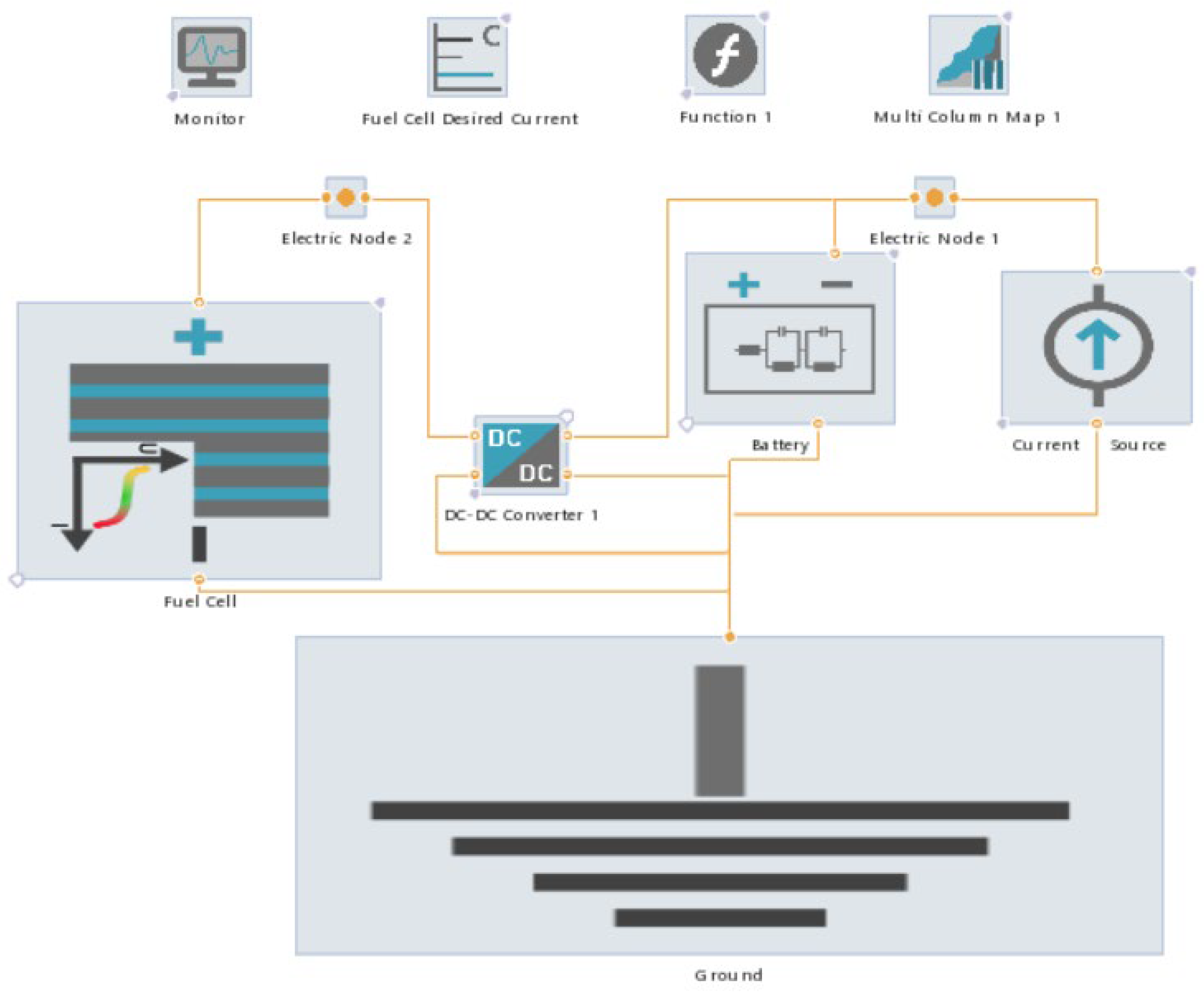
Figure 2 illustrates a schematic of the power module utilized in lift trucks, combining both a fuel cell system (FCS) and a battery. The battery is directly linked to the DC bus, while the FCS is connected to the bus via a unidirectional DC/DC converter, facilitating precise control over the FCS’s power output. Additionally, a bidirectional DC/DC converter precedes the battery, functioning at different voltage levels and providing the capability to manage power effectively. This bidirectional operation allows for both discharging and charging of the battery.
This topology, as depicted in Figure 2, represents the conventional approach employed in lift trucks, as documented in the literature (reference [34]). It is favored for its numerous advantages over alternative topologies. Notably, in this configuration, the DC bus voltage aligns with the battery voltage, eliminating the need for direct bus voltage regulation.
The fuel cell model is constructed upon analytical electrochemical equations derived from the polarization curve observed on the cathode side of the Proton Exchange Membrane Fuel Cell (PEMFC). This model offers an approximate solution that factors in oxygen and proton transport losses occurring in the Catalyst Coated Layer (CCL), as well as oxygen transport losses within the Gas Diffusion Layer (GDL). It accounts for variations in temperature, relative humidity, and gas pressure on the cathode side.
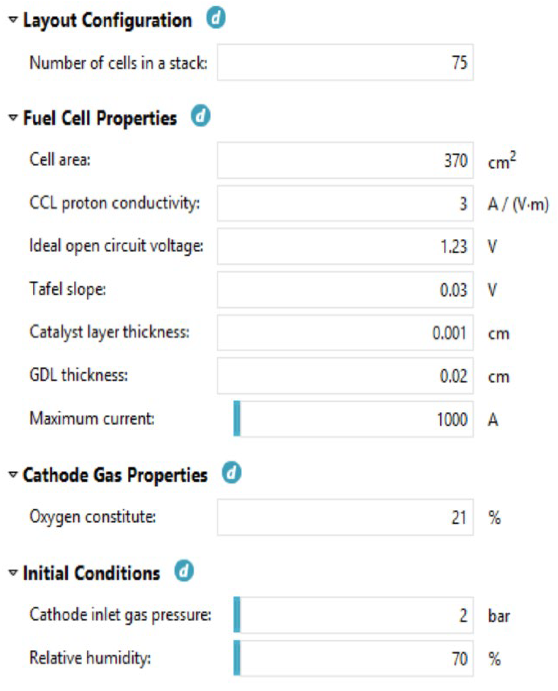
This versatile model serves the purpose of assessing both electrical characteristics, such as the voltage, power output, power losses, and efficiency of the fuel cell, as well as gas-related properties, such as the total consumption of oxygen and hydrogen. Moreover, within the fuel cell component, there exists the option to activate a simplified compressor model. This inclusion allows for the consideration of the compressor’s power consumption, a critical factor significantly impacting the operational efficiency of the entire fuel cell system. Key properties of the fuel cell are detailed in Figure 3.
The term “Oxygen constitute” refers to the purity level of oxygen in the gas supplied to the cathode at its inlet. Meanwhile, “Cathode inlet gas pressure (absolute)” represents the absolute gas pressure measured at the entrance of the cathode. It is important to note that if an internal compressor is employed in the system, this input parameter would be substituted by the compressor outlet pressure.
The operational parameters encompass the temperature, pressure, relative humidity, and the stoichiometric ratio of the reactant gases. These variables play a pivotal role in shaping the system’s performance.
Moreover, the system’s load profile adheres rigorously to the established standards detailed in VDI 60 for material handling applications, as visually presented in Figure 4. This profile offers a well-structured representation of the system’s operation across diverse conditions and serves as a fundamental tool for assessing its real-world performance.
Heavy-duty tests of the forklift were carried out according to the VDI 60/VDI 2198 standard protocol. Note that the duration of the driving/lifting/dropping cycle was ~1 min (60 cycles per 1 h), and the distance, L, between lifting/dropping points was 30 m. The model was validated by comparing the hydrogen consumption calculated during simulations with the one measured during the real VDI60 test of the forklift.

4. Results and Discussion

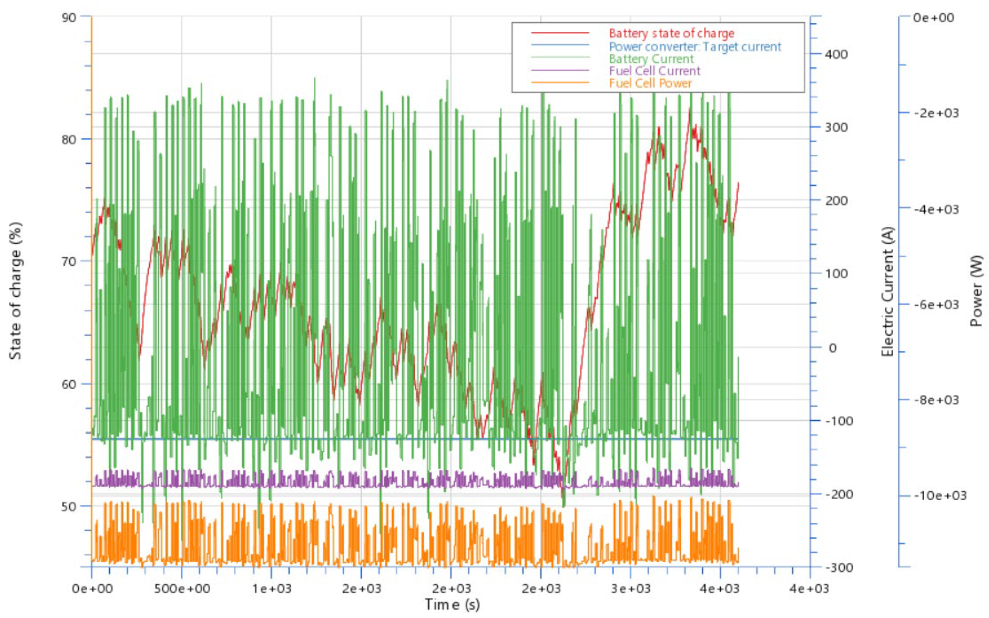
In this chapter, we will present the simulation results. To effectively incorporate the hybrid functionalities into the forklift, we employed the AVL—Cruise M program. Before initiating the simulation, it is crucial to establish the driving conditions to which the vehicle will be subjected. Based on these conditions, we select the appropriate driving cycle. Driving cycles provide a description of the real-world loads that the vehicle may encounter during operation. Figure 5 highlights the key characteristics associated with default values for this purpose.
The stack comprises 75 fuel cells, each with a cell area of 370 square centimeters. The battery operates at a voltage of 75 volts and possesses a rated capacity of 25 ampere-hours (Ah). Under default conditions, the current is set at 125 amperes (A), which maintains the fuel cell’s power output at 11 kilowatts (kW). Notably, the state of charge (SOC) of the battery remains at a reasonable level throughout the operation.
When the battery’s SOC reaches 50%, the fuel cell begins supplying power to the battery. Conversely, when the SOC reaches 82%, the fuel cell ceases its operation. Importantly, the fuel cell maintains a stable output current throughout the operation, and its power output gradually adjusts to match the load power request, effectively mitigating the impact of abrupt load changes on the fuel cell. The battery’s charging and discharging follow the load’s power requirements.
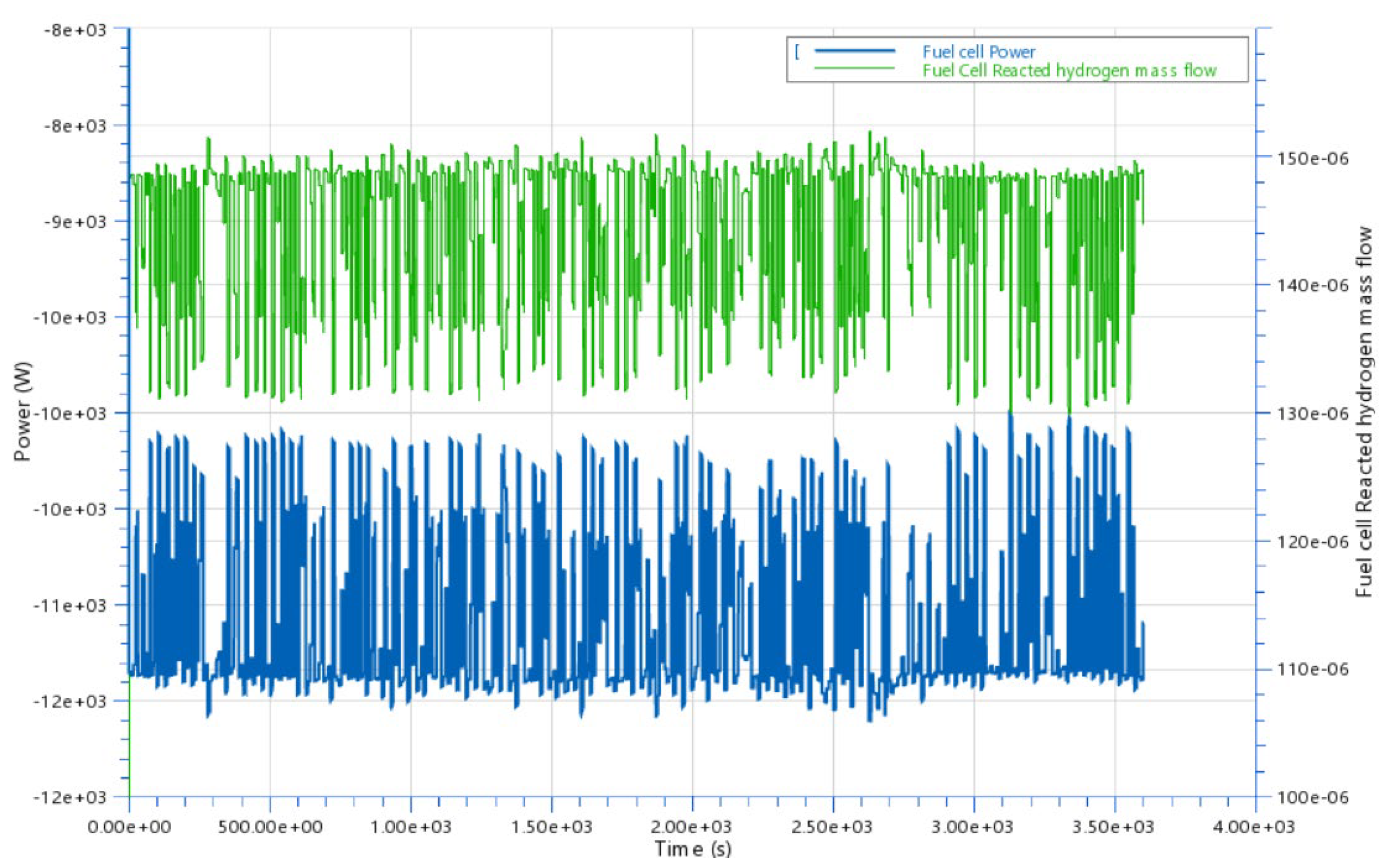
The reacted hydrogen mass flow ranges between 0.13 g per second and 0.15 g per second. When recalculated under “normal” conditions, this translates to an amount between 10 normal liters per minute (Nl/min) and 15 Nl/min per 1 kilowatt, as illustrated in Figure 6. In total, the reacted hydrogen mass amounts to 0.51 kg and the fuel cell energy is 39.7 MJ during the VDI60 cycle (duration—1 h).

4.1. Design of Experiment

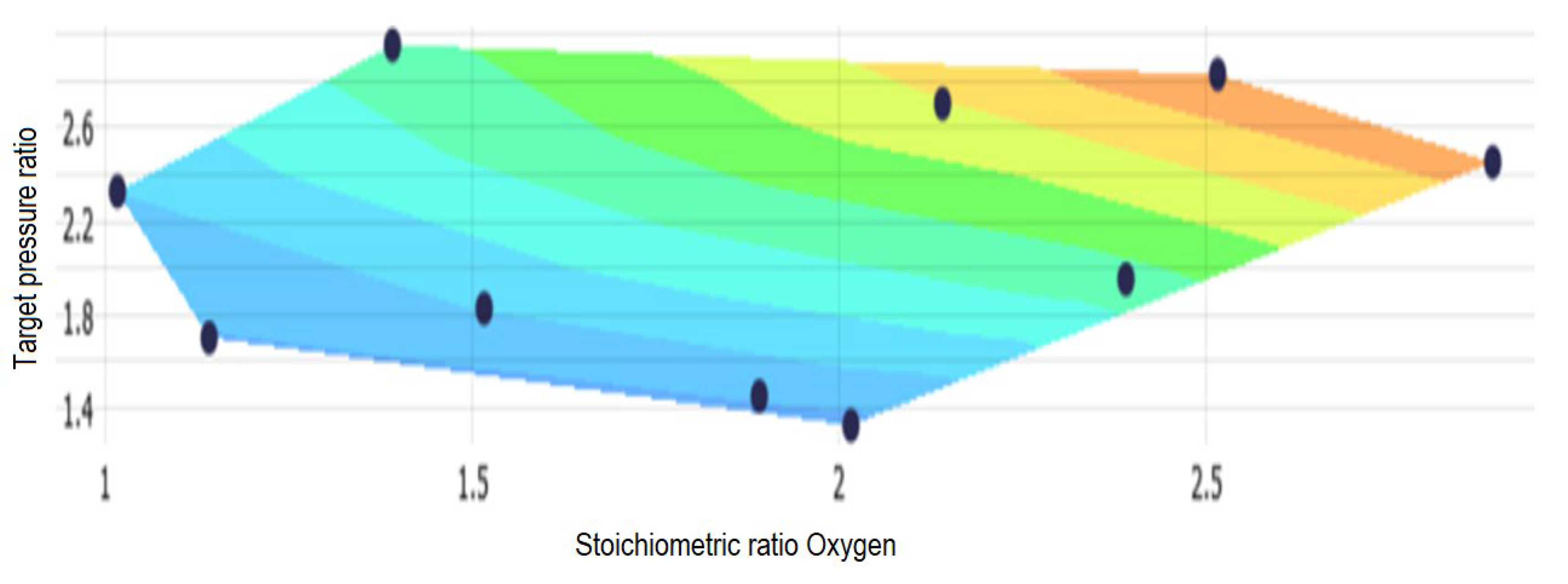
The Design of Experiment (DOE) gives a selection of design points, for which the numerical simulations should be evaluated. It is necessary to find good starting points for the optimization process. The DoE called space filling design is preferred for the search of a good starting design for the optimization.
The Design of Experiment is performed with the following Input/Output parameters as presented in Table 2:
The input parameters comprise the Oxygen Stoichiometric ratio and the Air Pressure ratio. The primary objectives are to minimize energy consumption and hydrogen usage. The obtained results indicate that these objectives are successfully attained at pressure ratios of 2.5 and Stoichiometric ratios of 2.8 and 3, as detailed in Table 3 and illustrated in Figure 7.
The compressor power at an optimized load is 1491 W, and the hydrogen consumption is 0.5147 kg during the simulated VDI60 load cycle.

4.2. The Nelder–Mead Optimization Algorithm

The Nelder–Mead optimization algorithm, or simplex search algorithm, is used for multidimensional unconstrained optimization. The method does not require any derivative information, which makes it suitable for problems with non-smooth functions.
The following objectives are defined: Energy Consumption, Cumulated Hydrogen Mass Consumption, and Mean Compressor Power.
For the Nelder–Mead optimization algorithm, the following variables are determined and analyzed: the Oxygen Stoichiometric Rate (in a range of 2–3) and Pressure Rate (in a range of 1.5–3), suggested by the results obtained with the DOE analysis.
The design points for optimization are defined by the Sobol sequence (Table 4), which is a quasi-random sequence, due to their common use as a replacement of uniformly distributed random numbers. The advantage of this method is that a great part of the design space is covered by a small number of design points.
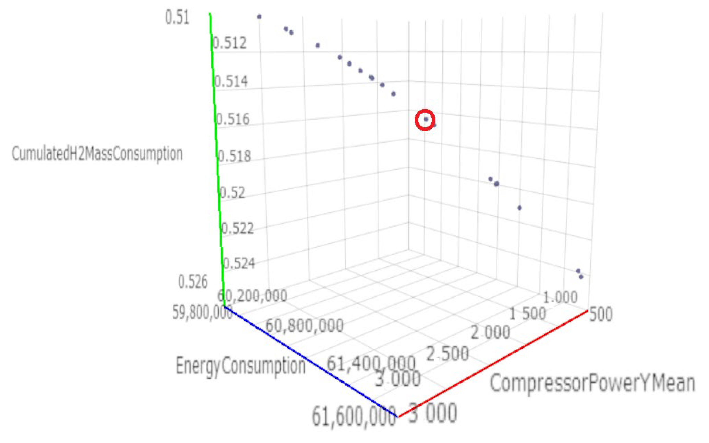
The optimization gives the following optimal results (area marked in red) (Figure 8):
-
Energy Consumption 60,426 kJ (or 16,785 kWh)
-
Cumulated Hydrogen Mass Consumption 0.5143 kg
-
Mean Compressor Power 1543.68 W
The highest objective is achieved with a pressure ratio of 1.512 and an Oxygen Stoichiometric ratio of 2.7266.

4.3. Analysis of the Air Excess Ratio and the Pressure Ratio Influencing Parameters

Here is the analysis of the system’s minimum and maximum load scenarios, with the primary goal of optimizing excess air and pressure ratio parameters, especially under dynamic load conditions. The air compressor has the capability to deliver varying air pressures and mass flows to the fuel stack, and these operational parameters directly impact the compressor energy consumption, subsequently influencing the overall efficiency of both the stack and the system. This study is focused on optimizing the system efficiency with respect to air supply parameters, specifically the air excess ratio and pressure ratio.
Numerous simulations were conducted, exploring different combinations of air pressures and air excess ratios to enhance the system’s performance. The primary objective is to optimize the fuel cell performance while understanding the individual impacts of each parameter on the fuel cell efficiency, hydrogen consumption, and power loss. In this report, we present the key findings from these simulations.
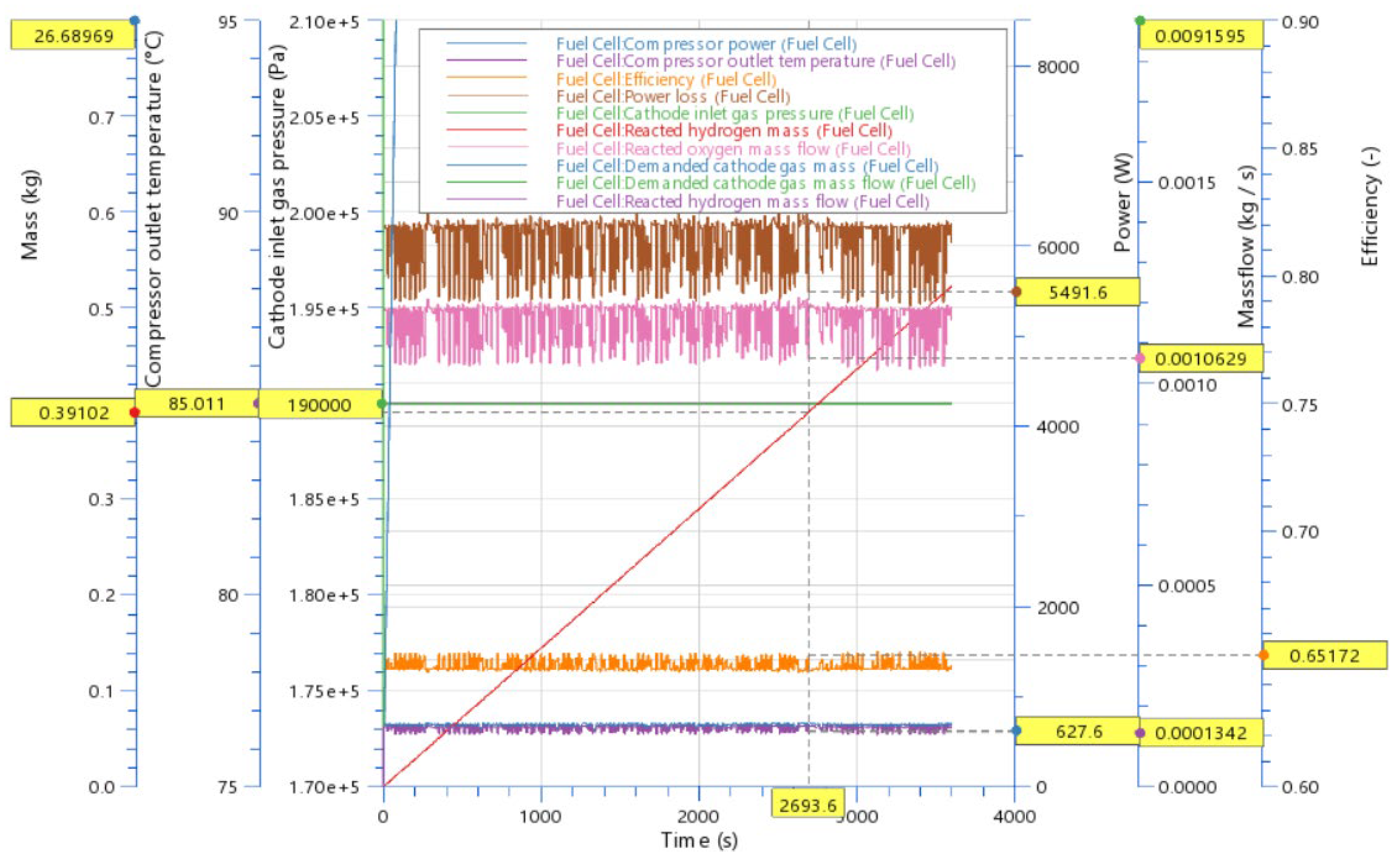
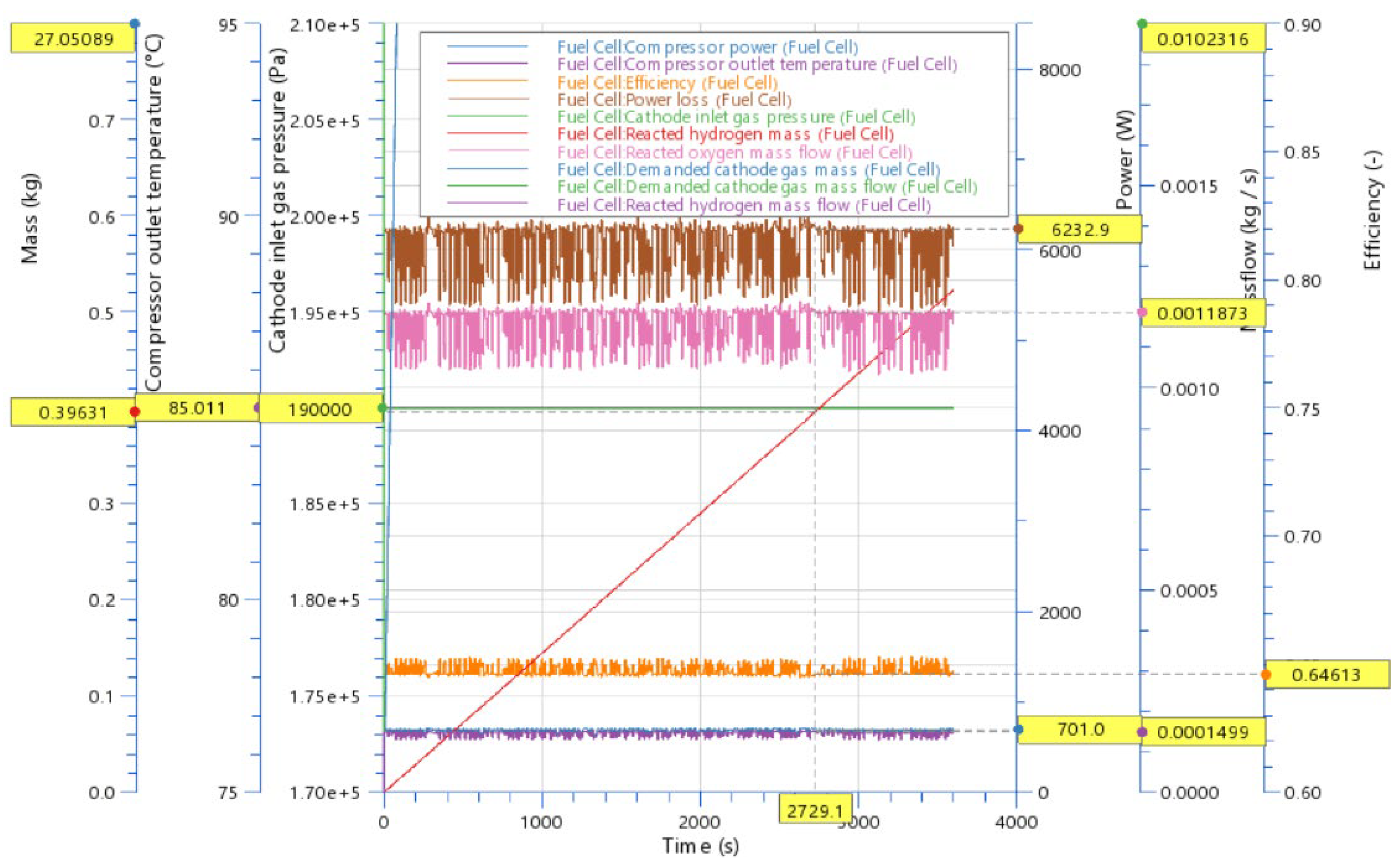
The first simulation was conducted with an air excess ratio of 2 and a pressure ratio of 1.9 (which is actually 1.9 bar, as the initial pressure is 1 bar), with the results detailed in Table 5. The data that are extracted from the graphical results are shown in Figure 9 and Figure 10. The analysis provides insights for two distinct points in time, denoted as Time 1 and Time 2, representing conditions that maximize and minimize the compressor power or system power loss.
Table 5 displays several crucial parameters, including the H2 Mass (the mass of hydrogen consumed during the VDO 60 load cycle, lasting 3600 s), Pcomp (the power of the air compressor), Eta (the fuel stack efficiency), and Power loss (the sum of all losses in the system). Additionally, we have included the following derived parameters: air mass, air mass flow, oxygen mass flow, and hydrogen mass flow, all presented at two distinct moments, and differences are calculated for each parameter.
The results show that the fuel cell efficiency varied between 65% and 64%, the compressor power ranged from 627 W to 701 W, and the hydrogen mass varied from 0.391 kg to 0.396 kg.
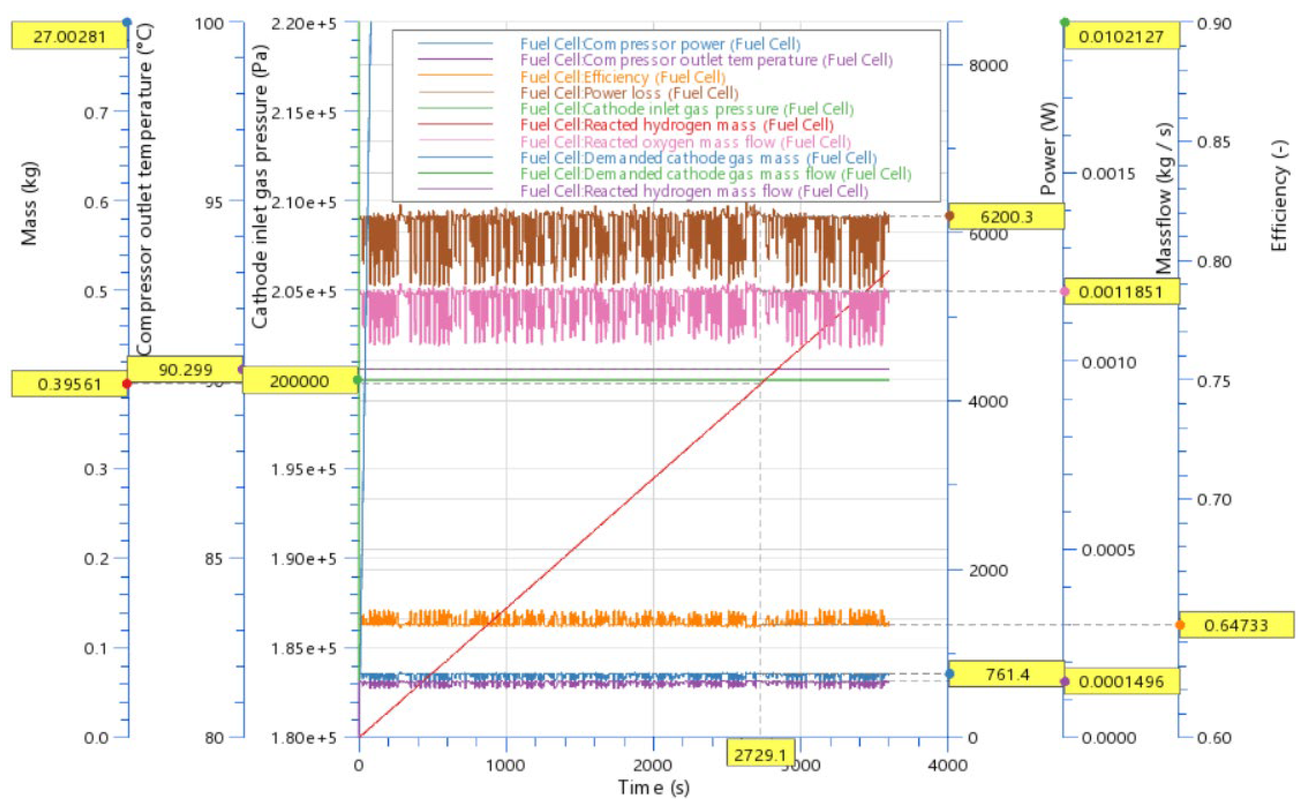
The second simulation is performed with an air excess ratio of 2 and an air pressure of 2 (bar) (Table 6, Figure 11 and Figure 12). The efficiency varied from 65.3 to 64.7%, the compressor power varied from 681 to 761 kW, and the hydrogen mass varied from 0.39 to 0.3956 kg
The third simulation is performed with an air excess ratio of 2 and an air pressure of 2.5 (bar) (Table 7). The efficiency varied from 65.7 to 65.2%, the compressor power varied from 926 to 1033 kW, and the hydrogen mass varied from 0.388 to 0.39305 kg. These parameters give the best fuel stack efficiency with the lowest hydrogen consumption.
The fourth simulation is performed with an air excess ratio of 2.5 and an air pressure of 2 (bar) (Table 8). The efficiency varied from 65.6 to 65.07%, the compressor power varied from 848 to 950 kW, and the hydrogen mass varied from 0.388 to 0.3925 kg.
From the above results, it can be seen that with an air stoichiometry of 2 and an air pressure ratio of 2.5 (Table 7), the best values of the parameters are obtained: the highest fuel cell efficiency (0.65655–0.6517), a lower hydrogen consumption (0.38788 kg), and the lowest power loss (5376.3–6082.2 W). The only parameter that is better at an air stoichiometry of 2.5 and an air pressure ratio of 2 (Table 8) is the hydrogen consumption, which is at a higher load point (0.39254 kg).

5. Conclusions

The aim of this research is to examine how the stoichiometric ratio of the air and the ratio of the air pressure affect the external characteristics of the fuel cell used in the power module installed in a forklift under a variable load. The model of the power module with a fuel cell is verified with the results obtained by testing a forklift with an installed tested module under variable loads according to the VDI 60 protocol for forklifts. With the Design of the experiment method, the initial values of the parameters of the stoichiometric ratio of air and the air pressure ratio were determined, considering the engaged power of the air compressor, the hydrogen consumption, and the total energy consumption. The optimization of the excess air parameters and air pressure ratio was performed with the Nelder–Mead optimization algorithm. An analysis of the influence of the parameters of the excess air and the air pressure ratio on the fuel cell efficiency, hydrogen consumption, and power loss during dynamic load changes was performed, observing the maximum and minimum load. The purpose of the research is to understand and determine the influence of the mentioned parameters in order to be able to determine the rule that would be applied in the control module for optimizing the power module with fuel cells under dynamic load change conditions.
Further research is needed to determine the impact of a variable excess oxygen ratio and to conduct numerical and experimental investigations of a regulator capable of tracking the optimal performance of fuel cells when regulating an excess oxygen ratio with different current disturbances/loads. As a future work, a controller of the optimal excess oxygen ratio will be established in the power module with fuel cells in real load conditions.

Author Contributions

Conceptualization, G.R, I.T. and S.P.; methodology, I.T. and G.R.; software, G.R.; validation, G.R. and I.T.; formal analysis, G.R., I.T. and S.P.; investigation, G.R., I.T., and M.V.L.; resources, G.R., I.T. and M.V.L.; data curation, G.R., I.T. and M.V.L.; original draft preparation, G.R.; writing, G.R., I.T. and M.V.L.; visualization, G.R. and I.T.; supervision, I.T. and M.V.L.; project administration, I.T. and M.V.L.; funding acquisition, G.R., I.T. and M.V.L. All authors have read and agreed to the published version of the manuscript.

Funding

This work has been fully supported by the European Commission, Grant Agreement number: 778307 HYDRIDE4MOBILITY H2020 MSCA RISE 2017 “HYDRIDE4MOBILITY” support of international collaboration, and the Croatian Science Foundation under the project IP.2020-02-6249. I. T. would like to acknowledge the support received from the project STIM—REI, contract number: KK.01.1.1.01.0003, funded by the European Union through the European Regional Development Fund—the Operational Programme Competitiveness and Cohesion 2014-2020 (KK.01.1.1.01.).

Data Availability Statement

The data used in this study are reported in the paper figures and tables.

Acknowledgments

The authors would like to thank HySA Systems, South African Institute for Advanced Materials Chemistry, University of the Western Cape for the contributions in experimental research and AVL, Graz for the software support.

Conflicts of Interest

The authors declare no conflict of interest.

References

  1. EurActiv. Available online: https://www.eceee.org/all-news/news/eu-unveils-300-million-plan-to-fund-hydrogen-research/ (accessed on 10 March 2022).
  2. Wu, H.-W. A review of recent development: Transport and performance modeling of pem fuel cells. Appl. Energy 2016, 165, 81–106. [Google Scholar] [CrossRef]
  3. Cunningham, J.M.; Hoffman, M.A.; Moore, R.M.; Friedman, D.J. Requirements for a flexible and realistic air supply model for incorporation into a fuel cell vehicle (fcv) system simulation. SAE Trans. 1999, 108, 3191–3196. [Google Scholar]
  4. Reshetenko, T.V.; Bender, G.; Bethune, K.; Rocheleau, R. Systematic study of back pressure and anode stoichiometry effects on spatial pemfc performance distribution. Electrochim. Acta 2011, 56, 8700–8710. [Google Scholar] [CrossRef]
  5. Matraji, I.; Laghrouche, S.; Jemei, S.; Wack, M. Robust control of the pem fuel cell air-feed system via sub-optimal second order sliding mode. Appl. Energy 2013, 104, 945–957. [Google Scholar] [CrossRef]
  6. Yan, S.; Yang, M.; Sun, C.; Xu, S. Liquid Water Characteristics in the Compressed Gradient Porosity Gas Diffusion Layer of Proton Exchange Membrane Fuel Cells Using the Lattice Boltzmann Method. Energies 2023, 16, 6010. [Google Scholar] [CrossRef]
  7. Kulikovsky, A. The effect of stoichiometric ratio on the performance of a polymer electrolyte fuel cell. Electrochim. Acta 2004, 49, 617–625. [Google Scholar] [CrossRef]
  8. Andjar, J.; Segura, F. Fuel cells: History and updating. a walk along two centuries. Renew. Sustain. Energy Rev. 2009, 13, 2309–2322. [Google Scholar] [CrossRef]
  9. Ji, S.W.; Myung, N.S.; Kim, T.S. Analysis of operating characteristics of a polymer electrolyte membrane fuel cell coupled with an air supply system. J. Mech. Sci. Technol. 2011, 25, 945–955. [Google Scholar] [CrossRef]
  10. Rabbani, A.; Rokni, M. Dynamic characteristics of an automotive fuel cell system for transitory load changes. Sustain. Energy Technol. Assess. 2013, 1, 34–43. [Google Scholar] [CrossRef]
  11. Lang, O.; Pischinger, S.; Schönfelder, C.; Steidten, T. Compressor expander units for mobile fuel cell systems. MTZ Worldw. 2004, 65, 29–32. [Google Scholar] [CrossRef]
  12. Boettner, D.D.; Paganelli, G.; Guezennec, Y.G.; Rizzoni, G.; Moran, M.J. Proton exchange membrane fuel cell system model for automotive vehicle simulation and control. J. Energy Resour. Technol. 2002, 124, 20–27. [Google Scholar] [CrossRef]
  13. Cunningham, J.; Hoffman, M.; Eggert, A.; Friedman, D. The implications of using an expander (turbine) in an air system of a pem fuel cell engine. In Proceedings of the 17th International Electric Vehicle Symposium & Exposition, Montreal, QC, Canada, 15–18 October 2000. [Google Scholar]
  14. Pischinger, S.; Schonfelder, C.; Bornscheuer, W.; Kindl, H.; Wiartalla, A. Integrated air supply and humidification concepts for fuel cell systems. SAE Trans. 2001, 110, 86–92. [Google Scholar]
  15. Jung, G.-B.; Lo, K.-F.; Su, A.; Weng, F.-B.; Tu, C.-H.; Yang, T.-F.; Chan, S.H. Experimental evaluation of an ambient forced-feed airsupply opem fuel cell. Int. J. Hydrogen Energy 2008, 33, 2980–2985. [Google Scholar] [CrossRef]
  16. Sun, T.; Zhang, X.; Chen, B.; Liu, X. Coordination control strategy for the air management of heavy vehicle fuel cell engine. Int. J. Hydrogen Energy 2020, 45, 20360–20368. [Google Scholar] [CrossRef]
  17. Gelfi, S.; Stefanopoulou, A.G.; Pukrushpan, J.T.; Peng, H. Dynamics of low-pressure and high-pressure fuel cell air supply systems. In Proceedings of the 2003 American Control Conference, Denver, CO, USA, 4–6 June 2003; IEEE: Piscataway, NJ, USA, 2003; Volume 3, pp. 2049–2054. [Google Scholar]
  18. Tafaoli-Masoule, M.; Shakeri, M.; Esmaili, Q.; Bahrami, A. Pem fuel cell modeling and pressure investigation. Energy Source Part A 2011, 33, 2291–2302. [Google Scholar] [CrossRef]
  19. Ahmadi, N.; Dadvand, A.; Rezazadeh, S.; Mirzaee, I. Analysis of the operating pressure and gdl geometrical configuration effect on pem fuel cell performance. J. Braz. Soc. Mech. Sci. Eng. 2016, 38, 2311–2325. [Google Scholar] [CrossRef]
  20. Kim, H.-S.; Lee, D.-H.; Min, K.; Kim, M. Effects of key operating parameters on the efficiency of two types of pem fuel cell systems (high-pressure and low-pressure operating) for automotive applications. J. Mech. Sci. Technol. 2005, 19, 1018–1026. [Google Scholar] [CrossRef]
  21. Blunier, B.; Miraoui, A. Air management in pem fuel cells: State-of-the-art and prospectives. In Proceedings of the 2007 International Aegean Conference on Electrical Machines and Power Electronics, Bodrum, Turkey, 10–12 September 2007; IEEE: Piscataway, NJ, USA, 2007; pp. 245–254. [Google Scholar]
  22. Kim, D.K.; Min, H.E.; Kong, I.M.; Lee, M.K.; Lee, C.H.; Kim, M.S.; Song, H.H. Parametric study on interaction of blower and back pressure control valve for a 80-kw class pem fuel cell vehicle. Int. J. Hydrogen Energy 2016, 41, 17595–17615. [Google Scholar] [CrossRef]
  23. Hoeflinger, J.; Hofmann, P. Air mass flow and pressure optimisation of a PEM fuel cell range extender system. Int. J. Hydrogen Energy 2020, 45, 29246–29258. [Google Scholar] [CrossRef]
  24. Yan, Q.; Toghiani, H.; Causey, H. Steady state and dynamic performance of proton exchange membrane fuel cells (PEMFCs) under various operating conditions and load changes. J. Power Sources 2006, 161, 492–502. [Google Scholar] [CrossRef]
  25. Schroter, J.; Graf, T.; Frank, D.; Bauer, C.; Kallo, J.; Willich, C. Influence of pressure losses on compressor performance in a pressurized fuel cell air supply system for airplane applications. Int. J. Hydrogen Energy 2021, 46, 21151–21159. [Google Scholar] [CrossRef]
  26. Hu, D.; Yang, L.; Yi, F.; Hu, L.; Yang, Q.; Zhou, J. Optimization of speed response of super-high-speed electric air compressor for hydrogen fuel cell vehicle considering the transient current. Int. J. Hydrogen Energy 2021, 46, 27183–27192. [Google Scholar] [CrossRef]
  27. Novotný, J.; Nováková, L.; Čížek, R.; Kašpárek, M.; Machovská, I. Optimization of air mass flow in a PEM fuel cell. EPJ Web Conf. 2022, 264, 01026. [Google Scholar] [CrossRef]
  28. Chen, H.; Liu, Z.; Ye, X.; Yi, L.; Xu, S.; Zhang, T. Air flow and pressure optimization for air supply in proton exchange membrane fuel cell system. Energy 2022, 238, 121949. [Google Scholar] [CrossRef]
  29. Rezk, H.; Wilberforce, T.; Olabi, A.G.; Ghoniem, R.M.; Sayed, E.T.; Ali Abdelkareem, M. Optimal Parameter Identification of a PEM Fuel Cell Using Recent Optimization Algorithms. Energies 2023, 16, 5246. [Google Scholar] [CrossRef]
  30. Tang, X.; Zhang, Y.; Xu, S. Experimental study of PEM fuel cell temperature characteristic and corresponding automated optimal temperature calibration model. Energy 2023, 283, 128456. [Google Scholar] [CrossRef]
  31. Lototskyy, M.V.; Tolj, I.; Parsons, A.; Smith, F.; Sita, C.; Linkov, V. Performance of electric forklift with low-temperature polymer exchange membrane fuel cell power module and metal hydride hydrogen storage extension tank. J. Power Sources 2016, 316, 239–250. [Google Scholar] [CrossRef]
  32. Kulikovsky, A.A. A physically-Based Analytical Polarization Curve of a PEM Fuel Cell. J. Electrochem. Soc. 2014, 161, F263–F270. [Google Scholar] [CrossRef]
  33. Goessling, S.; Klages, M.; Haußmann, J.; Beckhaus, P.; Messerschmidt, M.; Arlt, T.; Kardjilov, N.; Manke, I.; Scholta, J.; Heinzel, A. Analysis of liquid water formation in polymer electrolyte membrane (PEM) fuel cell flow fields with a dry cathode supply. J. Power Sources 2016, 306, 658–665. [Google Scholar] [CrossRef]
  34. Radica, G.; Tolj, I.; Markota, D.; Lototskyy, M.V.; Pasupathi, S.; Yartys, V. Control strategy of a fuel-cell power module for electric forklift Share. Int. J. Hydrogen Energy 2021, 46, 35938–35948. [Google Scholar] [CrossRef]
Figure 1. Simplified schematics of the on-board system. 1 hydrogen storage and supply subsystem: 1.1 gas cylinder, 1.2, 1.3 e-adapters, 1.4, 1.5 pressure sensors, 1.6 refuelling receptacle, 1.7 check valve, 1.8 reducer, 1.9 recirculation pump, 1.10 purge valve. 2 MH extension tank: 2.1 hydrogen subsystem: 2.1.1 MH containers, 2.1.2, 2.1.3 shut-off valves, 2.1.4 gas filter; 2.2 thermal management subsystem: 2.2.1 water tank, 2.2.2 circulation pump, 2.2.3 radiator. 3 FC stack cooling subsystem: 3.1 coolant pump, 3.2 DI filter, 3.3 bypass valve, 3.4 radiator. 4 fuel/oxidant conditioning: 4.1 reactants conditioner, 4.2 humidifier assembly. 5 air supply subsystem: 5.1 filter, 5.2 flow meter, 5.3 compressor. 6 electrical components: 6.1 contactor, 6.2 Li-ion battery, 6.3 system master controller, 6.4 compressor motor controller, 6.5 cell voltage monitor, 6.6 BoP sensors (H2, tilt, coolant temperature, and oxidant and fuel temperatures), 6.7 battery sensors (voltage, current, and SoC), 6.8 stack sensors (voltage, current, and temperature) [31].
Energies 17 00120 g001
Figure 2. PEM Fuel Cell Battery Power Pack Model.
Energies 17 00120 g002
Figure 3. Fuel cell properties.
Energies 17 00120 g003
Figure 4. VDI 60 Load profile.
Energies 17 00120 g004
Figure 5. Simulation 1—Battery capacity 25 Ah, fuel cell power 11 kW FC: 75 cells_370 cm2; Bat.: 75 V 25 Ah; Current −125 A.
Energies 17 00120 g005
Figure 6. Reacted Hydrogen Mass Flow (kg/s).
Energies 17 00120 g006
Figure 7. DOE results with the air pressure ratio and stoichiometric ratio of oxygen. Orange represents the area with the highest achieved objectives and lowest hydrogen consumption. Blue represents the area with a higher consumption.
Energies 17 00120 g007
Figure 8. Optimization results with a dependency on three inputs: Energy Consumption (J), Cumulated Hydrogen Mass Consumption (kg), and Mean Compressor Power (W). Optimal results marked in red circle.
Energies 17 00120 g008
Figure 9. Obtained results with an air excess ratio of 2 and a pressure ratio of 1.9 at Time 1 (marked in yellow).
Energies 17 00120 g009
Figure 10. Obtained results with an air excess ratio of 2 and a pressure ratio of 1.9 at Time 2.
Energies 17 00120 g010
Figure 11. Obtained results with an air excess ratio of 2 and a pressure ratio of 2 at Time 1.
Energies 17 00120 g011
Figure 12. Obtained results with an air excess ratio of 2 and a pressure ratio of 2 at Time 2.
Energies 17 00120 g012
Table 1. Power module balance of plant components and their contribution in the power consumption.
Part of the Power Module BoPPower Consumption (W)
Power module electronics143.6
Power of PEM Fuel cell stack
power module BoP components for proper operation
1058.8
MH thermal management system313.8
TOTAL1516.2
Table 2. DOE input–output parameters.
Correlate ParametersInput/Output
Stoichiometric Ratio OxygenInput
Target Pressure RatioInput
Compressor Power MeanOutput
Cumulated Hydrogen Mass ConsumptionOutput
Energy ConsumptionOutput
ObjectiveOutput
Table 3. DOE input–output parameters with objectives.
Target Pressure Ratio [-]Stoichiometric Ratio Oxygen [-]Compressor Power Mean [W]Cumulated Hydrogen Mass Consumption [kg]Objective
2.531491.060.514730.94
2.52.81393.090.515217.43
2.52.51246.20.51626.132
231097.210.51752.348
2.521001.710.51861.88
22.5917.370.51921495
22737860.5220.96
1.53621.440.52260.835
1.52.5519.950.52470.732
1.52418.730.52820.637
Table 4. Design points for optimization (defined by the Sobol sequence).
Stoichiometric_Ratio_Oxygen [-]Target_Pressure_Ratio [-]
12.91412.6367
22.41411.8867
32.16412.2617
42.66411.5117
52.72662.9180
62.22662.1680
72.47662.5430
82.97661.7930
92.85162.3555
102.35161.6055
Table 5. Results with an air excess ratio of 2 and a pressure ratio of 1.9.
Time 1Time 2DifferencesDifferences
Time s2693.62729.1 %
H2 Masskg0.3910.39631−176.9820.986601
PcompW627.6701−73.40.895292
Eta 0.651720.646130.005591.008652
Power lossW5491.66232.9−741.30.881067
Air masskg26.6897127.05091−0.36120.986647
Air mass flowkg/s0.009160.0102320.00107160.895231
Oxygen mass flowkg/s0.00106290.0011870.0001240.895450
Hydrogen mass flowkg/s0.0001340.000151−1.6 × 1050.891694
Table 6. Results with an air excess ratio of 2 and a pressure ratio of 2.
Time 1Time 2DifferencesDifferences
Time s2693.62729.1 %
H2 Masskg0.390320.39561−176.3160.986628
PcompW681.8761.4−79.60.895456
Eta 0.652760.647330.005431.008388
Power lossW5466.66200.3−733.70.881667
Air masskg26.642327.00284−0.360540.986648
Air mass flowkg/s0.0091450.010213−0.001070.895454
Oxygen mass flowkg/s0.0010610.001185−0.000120.895452
Hydrogen mass flowkg/s0.0001340.00015−1.6 × 10 50.895722
Table 7. Results with an air excess ratio of 2 and a pressure ratio of 2.5.
Time 1Time 2DifferencesDifferences
Times2693.62729.1 %
H2 Masskg0.387880.39305−172.3160.986846
PcompW926.31033.4−107.10.896362
Eta 0.656550.65170.004851.007442
Power lossW5376.36082.2−705.90.88394
Air masskg26.6897126.82859−0.138880.994823
Air mass flowkg/s0.0090930.010144−0.001050.896413
Oxygen mass flowkg/s0.0010550.001177−0.000120.896517
Hydrogen mass flowkg/s0.0001330.000149−1.5 × 1050.896366
Table 8. Results with an air excess ratio of 2.5 and a pressure ratio of 2.
Time 1Time 2DifferencesDifferences
Times2694.12729.1 %
H2 Masskg0.388290.39254−141.6520.989173
PcompW848950.1−102.10.892538
Eta 0.65610.650710.005391.008283
Power lossW5387.16130.6−743.50.878723
Air masskg33.1926733.49227−0.29960.991055
Air mass flowkg/s0.0113750.012745−0.001370.892496
Oxygen mass flowkg/s0.0010560.001183−0.000130.892486
Hydrogen mass flowkg/s0.0001330.000149−1.6 x 10 50.892236
Disclaimer/Publisher’s Note: The statements, opinions and data contained in all publications are solely those of the individual author(s) and contributor(s) and not of MDPI and/or the editor(s). MDPI and/or the editor(s) disclaim responsibility for any injury to people or property resulting from any ideas, methods, instructions or products referred to in the content.