Article

Study of Supercapacitors Built in the Start-Up System of the Main Diesel Locomotive

by
Boris V. Malozyomov
1,
Nikita V. Martyushev
2,
Viktor Alekseevich Kukartsev
3,
Vladislav Viktorovich Kukartsev
4,5,6,
Sergei Vasilievich Tynchenko
7,8,
Roman V. Klyuev
9,*,
Nikolay A. Zagorodnii
10 and
Yadviga Aleksandrovna Tynchenko
11,12
1
Department of Electrotechnical Complexes, Novosibirsk State Technical University, 20, Karl Marks Ave., 630073 Novosibirsk, Russia
2
Department of Advanced Technologies, Tomsk Polytechnic University, 634050 Tomsk, Russia
3
Department of Materials Science and Materials Processing Technology, Polytechnical Institute, Siberian Federal University, 660041 Krasnoyarsk, Russia
4
Department of Informatics, Institute of Space and Information Technologies, Siberian Federal University, 660041 Krasnoyarsk, Russia
5
Department of Information Economic Systems, Institute of Engineering and Economics, Reshetnev Siberian State University of Science and Technology, 660037 Krasnoyarsk, Russia
6
Digital Material Science: New Materials and Technologies, Bauman Moscow State Technical University, 105005 Moscow, Russia
7
Department of Digital Control Technologies, Institute of Business Process Management, Siberian Federal University, 660041 Krasnoyarsk, Russia
8
Department of Computer Science and Computer Engineering, Institute of Computer Science and Telecommunications, Reshetnev Siberian State University of Science and Technology, 660037 Krasnoyarsk, Russia
9
Technique and Technology of Mining and Oil and Gas Production Department, Moscow Polytechnic University, 33, B. Semenovskaya Str., 107023 Moscow, Russia
10
Department of Operation and Organization of Vehicle Traffic, Belgorod State Technological University Named after V.G. Shukhov, Kostukov St., 308012 Belgorod, Russia
11
Laboratory of Biofuel Compositions, Siberian Federal University, 660041 Krasnoyarsk, Russia
12
Department of Systems Analysis and Operations Research, Reshetnev Siberian State University of Science and Technology, 660037 Krasnoyarsk, Russia
*
Author to whom correspondence should be addressed.
Energies 2023, 16(9), 3909; https://doi.org/10.3390/en16093909
Submission received: 26 March 2023 / Revised: 3 May 2023 / Accepted: 4 May 2023 / Published: 5 May 2023

Abstract

:
A successful guaranteed launch of a mainline diesel locomotive is one of the most important and urgent problems of the rolling stock operation. Improvement of the start-up system of the main diesel locomotive when using a supercapacitor allows multiple restarts of diesel locomotives, meaning that the operation of the diesel locomotive can be stopped several times without wasting fuel in idle operations. In this study, we simulated the electric starting circuit of a diesel locomotive with a block of supercapacitors using the Matlab Simulink program. The simulation results show that using only a supercapacitor in the start-up system is impossible. Even though the supercapacitor produces the required current and voltage, its operating time is extremely insufficient. Using a storage battery along with a supercapacitor in the diesel locomotive start-up system is most effective. This reduces the peak current load on the standard battery. The article suggests an effective principle for starting a mainline diesel locomotive and provides an effective circuit solution involving a supercapacitor. Based on the booster stabilizer scheme, a new scheme was modeled to study the successful launch of a diesel locomotive that has various start-up systems. Applying a supercapacitor in the start-up system of a main diesel locomotive is proposed and the results of its use are presented. In addition, this study defines the basic requirements for using a system based on a battery in conjunction with a supercapacitor. Characteristics such as the temperature range of the system are shown.

1. Introduction

Starting an engine is a necessary condition for the operation of any power plant. Arranging the start of a diesel engine of a railway locomotive always requires additional equipment; this complicates and increases the cost of the engine, which then requires additional maintenance, and its starting is always accompanied by a reduction in engine life, excessive fuel consumption, and increased emissions of toxic components. At low engine temperatures (“cold” engine) and ambient air, engine start-up becomes more difficult; the start-up reliability is significantly reduced, and the preparation time for load acceptance increases.
The problem of starting diesel locomotives in cold climates is relevant for different countries, such as the northern areas of the USA, Canada, Denmark, Finland, Iceland, Norway, Sweden, northern regions of China (including Tibet), and Russia. There are various solutions that consider various regional features of technology and the climate. The work in in this field is also far from complete, as evidenced by publications in 2023 [1] and 2021 [2].
Currently, there is an increase in energy consumption all over the world accompanied by a reduction in the resource base. This makes the task of economical use extremely relevant. One of the most significant consumers of energy (in the forms of electricity and combustible fuel) is rail transport. The main traction force on the railway is mainline electric locomotives and diesel locomotives. If electric locomotives are a well-developed and environmentally friendly technique, then diesel locomotives raise many environmental issues when operating [3].
This article is the result of research within the framework of the world’s largest railway transport company, Russian Railways (https://eng.rzd.ru/en/10773 (accessed on 20 September 2022)). Over the past few years, this company has significantly updated its rolling stock, renovated railway stations, purchased dozens of Siemens high-speed trains, etc. At the same time, Russian Railways initiated the research needed to solve the problem of starting diesel locomotives in a cold climate. This indicates the urgency of the problem.
A diesel locomotive is the most common type of locomotives in the world today. About 85% of the approximately 1,200,000 km of main railways of the countries of the world are served exclusively by diesel traction (diesel locomotives). Diesel locomotives provide about 97% of the operating length of the main railways on the two American continents (North and South America) [3]. In Russia, diesel locomotives are distributed throughout the entire railway network and perform about 98% of shunting work and about 40% of passenger and freight traffic. At present, about 80% of the shunting diesel locomotive fleet consists of diesel locomotives of the TEM-2, ChME3, and TG16M-001 series with various modifications. The low efficiency of transport enterprises in the last decade is explained by the critical aging and unsatisfactory technical condition of the fleet of shunting diesel locomotives. This problem cannot be solved only by purchasing new diesel locomotives because the cost of a single unit of rolling stock is high. According to the Russian Railways, the annual volume of deliveries of diesel locomotives of the TEM18DM and TG16M-001 series was less than 100 units for 2010–2011. At the same time, according to the calculations of INFOLine analysts, at least 200 rolling stock units require replacement because of moral and physical deterioration.
In this regard, the most justified way to maintain the technical condition of the fleet of shunting diesel locomotives is a comprehensive modernization aimed at improving the energy performance and service life of the equipment. The main solution to the problem of modernization is to improve the system for starting the diesel engine of shunting diesel locomotives. The paper considers the possibility of using a supercapacitor battery [4,5] in diesel engine start systems for shunting diesel locomotives. The supercapacitor battery as part of the diesel locomotive start-up system allows the mechanical resistance to the crankshaft starting spin-up (1.5–2 s) to be overcome, which significantly reduces the peak current load on the standard battery at the initial start-up moment. Using a pulse control system allows the process of charging and discharging a supercapacitor battery to be controlled [6,7,8] and can reduce the capacity of a standard battery 1.5–2 times. It is not rational to completely abandon the use of the battery in the starting system due to an exposure to constant load in the form of oil and fuel pumps, lighting devices, and air and water heating devices. The total power of the above constant load is hundreds of kW. This paper considers the necessary parameters for calculation of an equivalent circuit in the diesel engine starting system and determines the optimal value of the electric capacitance of the supercapacitor battery to ensure a reliable start when working along with the battery, so that the engine is powered by the supercapacitor battery and the battery working together.
For mainline diesel locomotives, a successful guaranteed launch of a mainline diesel locomotive is one of the most important and currently relevant problems of the rolling stock operation [9]. An adequate solution to this problem significantly reduces the cost of diesel fuel and equipment maintenance. In recent years, the trend in the development of railway transport requires the rolling stock to comply not only with power standards, but also with environmental ones. It is necessary to reduce fuel consumption of the internal combustion engine and extend the service life of diesel locomotive batteries [10].
Due to inability of the battery to produce multiple restarts of diesel locomotives during parking, the engines of the rolling stock have to work in idling mode. As a result, up to 1000 L of fuel per month are consumed inappropriately by one rolling stock [11]. To save fuel and reduce harmful emissions into the atmosphere, one promising research directions for developing start-up systems for mainline diesel locomotives is the use of a block of supercapacitors [12]. Based on this, the measures aimed to modernize the regular system for starting the main diesel locomotive and ensuring a guaranteed start of the internal combustion engine are an extremely urgent task.
The purpose of this study is to find an effective solution for restarting the diesel engine of the main diesel locomotive and improving its start-up system by means of a supercapacitor.
To achieve this goal, the following tasks have been formulated:
  • To analyze the most modern methods for starting a diesel locomotive and identify the best options;
  • To simulate the electrical starting circuit in the Matlab Simulink program and determine the results of the start;
  • To develop the necessary parameters and make recommendations to researchers and developers of systems in starting diesel locomotives.
We solved the set tasks in several stages. To model the starting circuit of the main electric locomotive, it was necessary to determine the initial parameters. The selected starting method and equipment characteristics (supercapacitor capacity, charging time, electrolyte temperature, etc.) were the initial parameters. Based on this, firstly, we combined the review section of the article and the analysis of the theoretical material. At this stage, we analyzed the current state of knowledge in this area and chose an optimal way to start a diesel locomotive. Secondly, we simulated the starting circuit in the Matlab Simulink program [13]. Finally, we analyzed the obtained results.

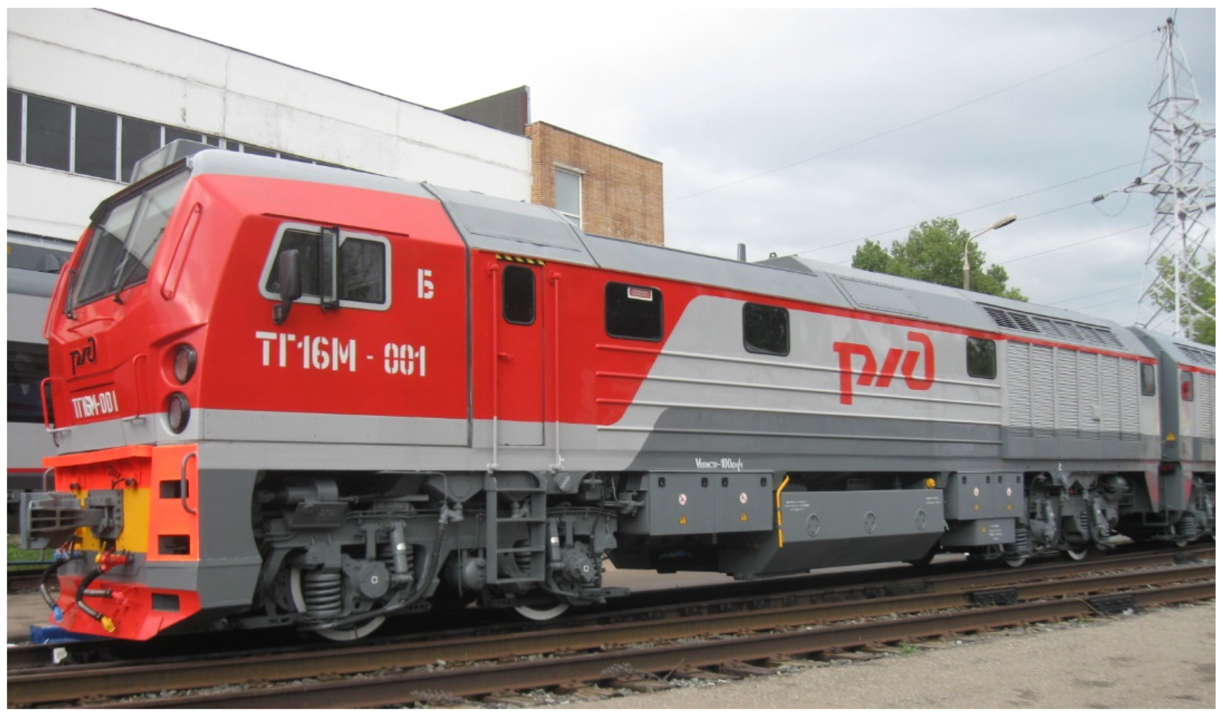
2. Locomotive. Launcher and Review of Existing Solutions

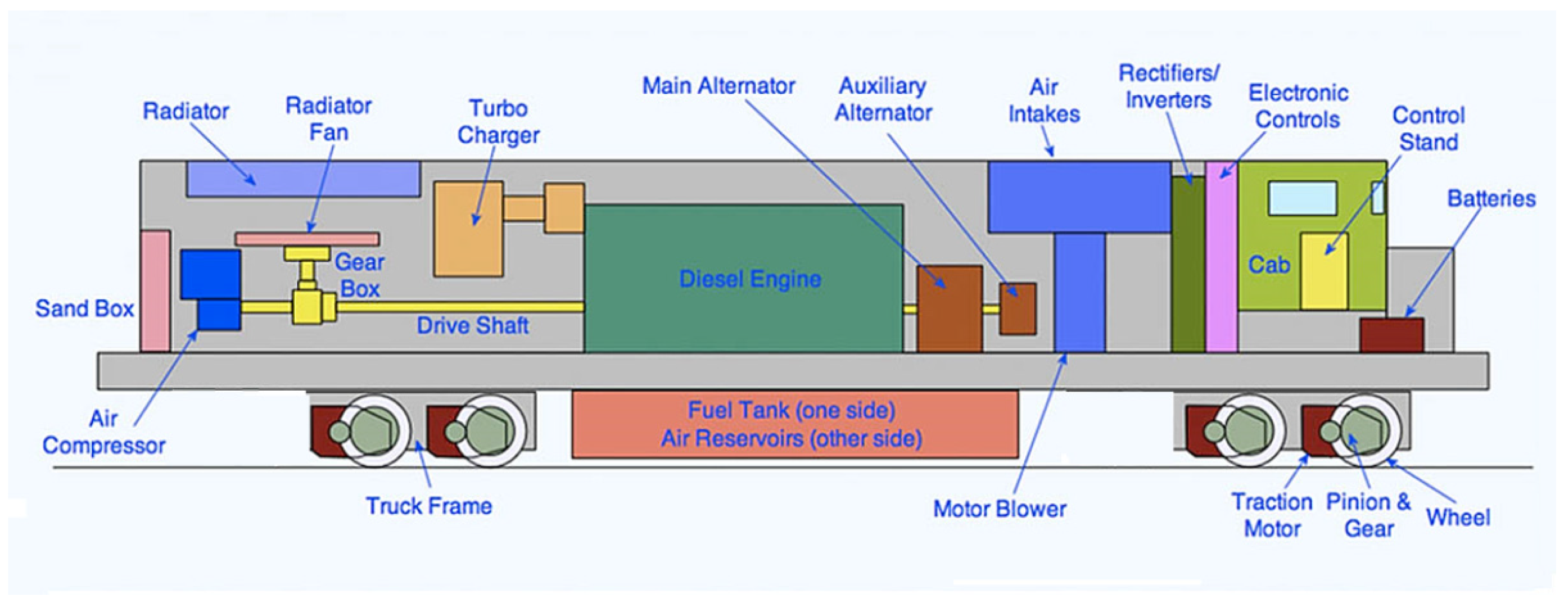
2.1. Locomotive Equipment

The TG16M-001 is a 1550-hp (1140 kW) diesel-electric locomotive built by GE Transportation Systems of Erie, Pennsylvania. GE’s locomotive series nicknames originated from the “Dash 7” of the 1970s, and the C44-9W was dubbed the Dash 9 upon its debut in 1993 [14].
The locomotive frame is mounted on two triaxial bogies. The body of a diesel locomotive consists of five main parts: a refrigeration chamber, a body above the diesel room, a body above the instrumental (high-voltage) chamber, a driver’s cab, and a body above the battery room. For the convenience of servicing the rolling stock, removable elements are installed on each of the five parts of the body, or, if such a design is impossible, the body is equipped with hatches in the roof and side doors.
There is a diesel room in the middle of the rolling stock, which houses a compressor and a diesel generator as the direct current source. The wheel sets move due to the electric current flow to the traction motors [15].
To provide the required diesel power (up to 1550 hp), six electric motors are connected in two parallel groups.
The modern diesel locomotive (Figure 1) is a self-contained version of the electric locomotive. Similar to the electric locomotive, it has an electric drive in the form of traction motors; this drives the axles that are being electronically controlled. There are many auxiliary systems for cooling, lighting, heating, braking, and powering (if required) the train. It can operate over the same routes (usually) and can be operated by the same drivers [16]. It differs principally by carrying its own generating station instead of being connected to a remote generating station through overhead wires or a third rail. The generating station consists of a large diesel engine coupled to an alternator producing the required electricity. A fuel tank is also essential.
A diesel locomotive, like an automobile, cannot start instantly. It will not develop maximum power at an idling speed; therefore, it requires some form of a transmission system to multiply the torque when starting. Varying the power applied relative to the train weight or the line gradient is also necessary. There are three methods of doing so: mechanical, hydraulic and electric. Most diesel locomotives have an electric transmission and are known as “diesel-electric” locomotives. Mechanical and hydraulic transmissions are still used, but they are more commonly applied on multiple unit trains or lighter locomotives [17].
The diagram (Figure 2) shows the main parts of a US-built diesel-electric locomotive, described in the subsequent paragraphs. The US example was selected because of its wide-spread use in the world. There are obviously many variations in the layout, including differentiations in the European practice. Some of these are noted below.
The diesel locomotive is started by a generator operating in the motor mode. The battery-powered generator transmits the torque to the compressor located behind the generator by means of V-belts to the two-machine unit to cool the traction motors of the rear bogie.
The fuel heater is located in the left front corner of the diesel room, and the water tank, which is divided into two compartments, is at the top. The spare oil tank is located on the right side of the same diesel room.
The refrigerating chamber located at the front of the TG16M-001 locomotive has cooling sections for water (to cool diesel and diesel charge air after the turbocharger) and oil.
Water and oil temperatures are regulated automatically by opening and closing the side and top shutters and turning the fan on and off.
The fuel tank is located under the main frame of the rolling stock. Four main brake reservoirs are fixed under it. All electrical wires are enclosed in special pipelines located in the frame and, partly, in the body of the locomotive.

2.2. Locomotive Start-Up Process

The order of starting operations in the diesel locomotive TG16M-001 are as follows. First, the fuel pump is turned on. Then, the oil pump drives the oil through the diesel locomotive, and within 30 s, the starting contactors close and the diesel engine starts [17].
The diesel locomotive should start smoothly without any abnormal knocks. If problems are identified, the diesel engine should be immediately stopped and not restarted until the identified causes of the malfunction are eliminated.
If the first start of the locomotive engine is unsuccessful, repeated starts are unacceptable, since they lead to battery discharge. There must be a 1–2 min interval between every new start.
The generator allows up to three repeated starts of the diesel engine, maintaining a five-minute interval in between each of them; the duration of each start is not more than 30 s. The total number of diesel start cycles should not exceed 10. When the 10 attempts are exhausted, repeated starts are allowed 6 h later, when the locomotive start system has completely cooled down [17].
In cold seasons, when the temperature of air, water, oil, and fuel drops below 8 °C, the start of the diesel engine is called “cold”. The duration of such launches increases.
The duration of starting a warm diesel engine, when the water and oil temperature is 40 °C or above, is not more than 12 s. The temperature of water and oil must not drop below 20 °C at the air temperature of 5 °C and below.
Oil and water systems at temperatures below 5 °C must be refueled with hot oil and water immediately before starting the diesel engine. The temperature of the refilled oil and water should be between 60 °C and 90 °C and between 40 °C and 60 °C, respectively. The cooling system should warm up to 40–60 °C. In other cases, all of the water must be drained, and the process should be repeated.
If starting a diesel engine is impossible in winter for some reason, and the temperature of the water and oil drops below 20 °C, the fluids must be drained.

2.3. Starting a Locomotive Equipped with a Battery
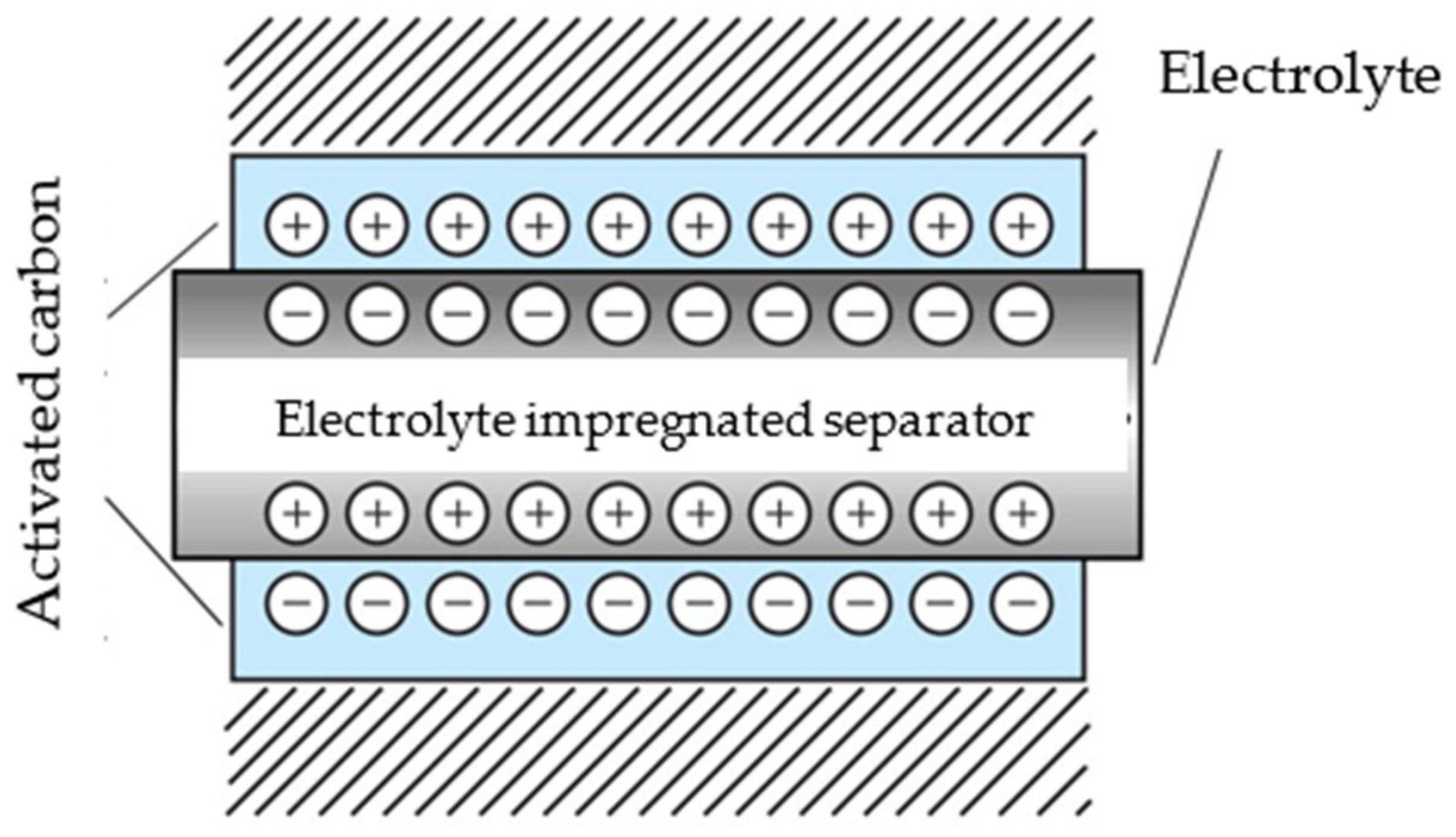
The main energy sources for railway transport are two types of batteries. Fast-discharge batteries are used as starter batteries, and long-discharge batteries are used as a backup source of an unlimited power supply [18].
Using powerful acid batteries as starter batteries is advantageous, and alkaline batteries can replace traction batteries [19]. Comparing acid and alkaline batteries reveals that that alkaline batteries are more toxic because of their prevailing cadmium content, and acid batteries are favorable in terms of weight, size and cost.
Railway transport has evolved from gas-hydraulic systems to electric starters. Electric starter systems are superior to gas-hydraulic ones in terms of weight, size, controllability and speed. Most importantly, the start-up time for electric starters is half as long, and the resulting efficiency is 30% higher [20]. The only problem is that the energy output stability directly depends on the ambient temperature.
A successful electric start of a diesel locomotive should occur in a maximum of 3 attempts, lasting for 15–20 s each. In this case, the minimum battery charge level should not fall below 75% of the nominal capacity [21].
The service life of the onboard starter battery is limited to five years [22]. The temperature regime should be maintained from −45 °C to +55 °C. In case of the normal operation during start-up, the battery charge is consumed to provide the required pressure in the system by starting the hydraulic pumps, and at low temperatures it is also used to heat the oil in the hydraulic system. Multiple starts of the locomotive diesel engine, reaching as many as 20–30 per day, in combination with low-temperature operating conditions, can cause a deep discharge of the battery [23].
The internal increase in the resistance of batteries is due to the presence of an electrolyte in their composition. The resistance of the electrolyte increases along with a decrease in the ambient temperature. A decrease in the ambient temperature by 1 °C entails a loss in the battery capacity of 1–1.5%. Under extreme conditions, when the air temperature drops below −30 °C, the battery is charged up to 50–60% of the nominal capacity. Figure 3 shows the dependence of the battery voltage in the starter mode on the electrolyte temperature [24].
A direct connection of the battery to the starter significantly discharges the battery by increasing the starting currents up to 2000–2300 A. A deep discharge of the battery (between 75% and below) is compensated by three or four hours of charge.
The analysis of the curves of current, voltage and power, presented in Figure 4, shows that, at the initial moment of starting, the maximum value of the starting current reaches 1550 A, and during the engine shaft operation, the voltage at the battery terminals decreases by 17 V. The diesel locomotive engine starts in 5.5 s, when the power delivered by the battery reaches 100 kJ.

2.4. Supercapacitor

Supercapacitors are also referred to as “ultracapacitors” or “electric double layer capacitors” (EDLC). EDLC rank as intermediate in the class of devices ranging between batteries and conventional capacitors. They justify their name by having a much larger capacity than electrolytic capacitors while having the same dimensions. The capacitance of EDLC exceeds the capacitance of “electronic” capacitors by an order of magnitude equal to 103.
Figure 5 shows the structure of a supercapacitor, whose supercapacitance is obtained by increasing the area of the plates and reducing the distance between them to a few nanometers [25]. Since the presence of the layers creates excess carriers that have an opposite polarity at the interface, the supercapacitor has a double electric layer.
Since the EDLC is an electrochemical component, its equivalent series resistance (ESR) when operating using a direct current is high [26]. Concerning the time dependence of the EDLC voltage shown in Figure 4, the voltage drop across magnitude is seen to occur at Δ U 1 R sharp. This is because the supercapacitor is discharging once it reaches the ESR load, when the voltage drops (curve Δ U Q ). The graph in Figure 6 shows that the resistive component of the EDFC impedance has a significant effect in the presence of large discharge current pulses. To avoid this, low ESR supercapacitors are used to work with large discharge current pulses Δ U Q [27].
The maximum recommended charging current is determined by the formula.
I = U 0 5 R
where U 0 is the charging voltage and R is the impedance of the supercapacitor.
In case of the maximum charging current, the EDLC can be charged by means of a direct current, a voltage source, or a battery connected to it in parallel [28].
The operating voltage of supercapacitors is small, ranging purely from 2.3 to 2.5 V. As a result, the EDLC can withstand a short-term increase in the voltage. In case of the continuous operation under increased voltage, manufacturers recommend using several sections of supercapacitors connected in series or in parallel/in series, depending on the number being used. Since the voltages of the EDLC are summed, this connection method allows the block of supercapacitors to operate at a high voltage while the effective capacitance is reduced. The disadvantage of the serial connection of the supercapacitor module is the uneven voltage drop of individual components and the excess of the permissible voltage value resulting from the mismatch of their parameters [29].
The supercapacitor has a wide operating temperature range, from −40 °C to +70 °C, but it does not tolerate exceeding the maximum even by 10 °C. Such increase in temperature, which is significant for the EDLC, reduces the service life of the EDLC twofold. Therefore, it is best to operate the supercapacitor at the lowest possible ambient temperature. If the temperature regime is impossible to maintain, the operating voltage is to be reduced. The same trend takes place at low temperatures. As a rule, the EDLC operation at low outdoor temperatures requires slightly increasing the operating voltage to compensate for the ESR increase. If the operating conditions are observed, the number of charge/discharge cycles of a supercapacitor reaches 500,000, and its service life exceeds 10 years [30].

2.5. System Designed for Starting a Diesel Locomotive Jointly Using a Storage Battery and a Supercapacitor

Since the batteries are not so durable (the service life is from 1 to 5 years), a comprehensive modernization is to be performed based on improving the energy performance and service life of the equipment. The main solution to this problem is the improvement of diesel locomotive start-up systems [31].
The unique power parameters of the supercapacitor (the ability to cover powerful short-term processes) allow starting a diesel locomotive along with a storage battery.
The supercapacitor power provides the maximum torque to spin the crankshaft when starting the engine. A power surge for 1.5–2 s allows the peak load on the standard battery to be reduced, which increases its service life by 1.5 times. The diesel engine output also increases, and its shutdown becomes real, which solves the main environmental problem as the diesel fuel consumption and the carbon dioxide emission into the atmosphere are reduced [32].
In recent years, manufacturers have been producing more powerful supercapacitors that are capable of storing 1–10 Wh/kg of energy. Their operating voltage is 1.3–5 V, and their power density reaches 1000 W/kg [33].
The comparison of Table 1 and Table 2 reveals a significant advantage of EDLC over lead-acid batteries in terms of specific power and allowable charge/discharge cycles. However, supercapacitors cannot be distinguished by their specific energy intensity; in the case of batteries, this figure averages 133 Wh/kg [34].

2.6. Chapter Conclusions

-
The diesel locomotive engine is allowed to be restarted, provided that there are intervals of 1–2 min, but the total number of repetitions should not exceed 10. The subsequent attempt to start the diesel locomotive can be made no earlier than 6 h, increasing the responsibility for importance systems, such as the starter.
-
It is established that, in most cases, the start is carried out using rechargeable batteries as starter devices. Usually, powerful acid batteries are used as traction batteries.
-
There should be a maximum of 3 attempts to perform starter launch. The duration of each attempt should not exceed 15–20 s.
-
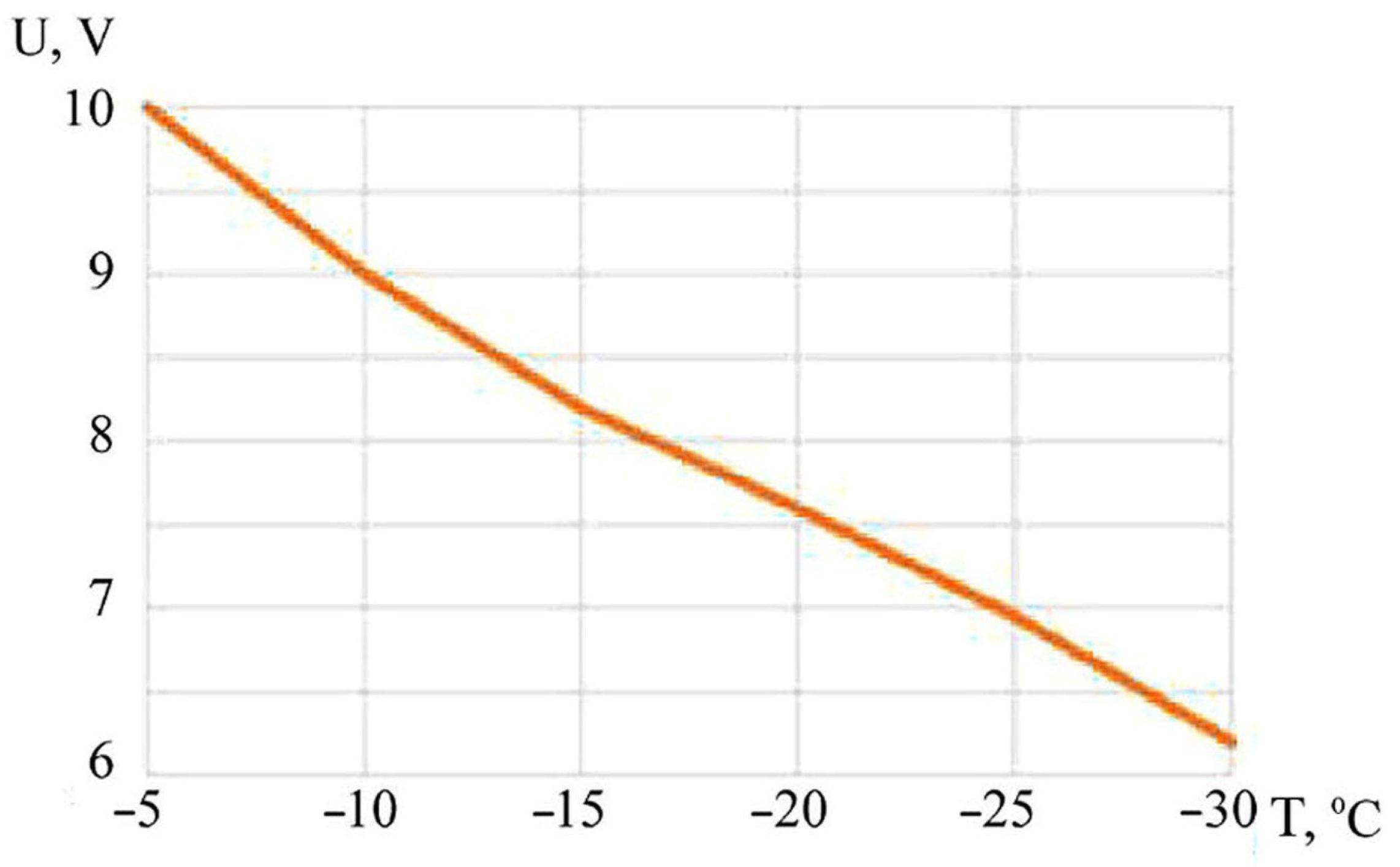
The rules set what range temperatures must be, i.e., within −45 °C and +55 °C. In this case, the service life of the onboard starter battery is from 1 to 5 years; when the air temperature is beyond the specified limits, the battery service life is halved.
-
It is found that, during a starter start-up using a battery, there are unsuccessful attempts of launching due to an insufficient amount of the energy supplied to the starter from the battery.
-
Methods have been proposed to solve the parallel operation of two sections of batteries, but due to the variations in the parameters of such batteries, it is not achieved (i.e., it is not possible to achieve equal voltage values on each of the two batteries).
-
This paper proposes using a supercapacitor as a source of high pulsed energy and duplication of the main power source: a battery.
-
Short-term attempts that exceed the recommended values of the working voltage (more than 2.3–2.5 V) are allowed, but in case of prolonged overloads, there is an increased risk of electrolyte decomposition.
-
The range of ambient temperatures for the EDLC operation is set from −20 to 70 °C, which exceeds the range of outdoor air temperatures for the battery operation.
-
An ESR increase has been determined to cause a reduction in the service life of supercapacitors. Operating properly, EDLC can withstand more than 500,000 charge/discharge cycles without changing the capacity, and their minimum service life reaches 10 years.
-
Joint use of batteries and EDLC to start a diesel locomotive is suggested. This solution is effective when there is the starting system of the locomotive traction engine.
-
The positive aspects of this method are the reduction in the peak current load on the standard battery at the initial start-up moment due to the maximum torque in the initial period of the engine shaft cranking; an 1.5-fold increase in the system service life; a 1.5–2-fold decrease in the capacity of a standard battery and, consequently, a decrease in its cost.

3. Modeling the Start-Up System of the Main Diesel Locomotive in the Matlab Simulink Development Environment

Achieving the goal set in this study for determining the optimal value of the electric capacitance of a supercapacitor battery for the implementation of the “cold” mode of starting a diesel engine when the storage battery and the supercapacitors battery work together required solving several problems related to real and simulation experiments. We needed to solve the research problems to determine the parameters of the regular diesel locomotive start system and circuits and to build the dependence of the starting voltage on time during restarts, the dependence of the starting current on time during restarts, and the choice of equivalent circuit parameters. Based on the obtained data, we built a model to implement the “cold” mode of starting a diesel engine, with the joint operation of a storage battery and a battery of supercapacitors. We also conducted experimental studies to confirm the model based on the values of starting currents and voltages.
The diesel locomotive start-up system is modeled in the Simulink program. A diesel locomotive engine start system consisting of one storage battery and one supercapacitor serves as an experimental model.

3.1. Simulation of a Regular Diesel Locomotive Start-Up System

It is necessary to create a model of a regular diesel locomotive start system to determine the optimal value of a supercapacitor battery’s electric capacity so that the mode of starting a diesel locomotive when the regular battery and the battery of supercapacitors work together can be implemented. This model should take into account the characteristics of the starter battery and a typical diesel starting system, which includes a starter-generator, an on-board battery, and switching equipment that has a pulsation generator. When designing the equivalent circuit, factors that change the characteristics of elements over time, such as battery discharge, are to be considered. Taking into account these factors requires that the characteristics change functions be programmed during the locomotive start-up. For this purpose, the MATLAB/Simulink computer mathematics system and the principle of simulation modeling are used, and the system under study is replaced by a model that describes the real system at a sufficient accuracy (the constructed model describes the processes as they would take place in reality). The experiments are carried out using this model to obtain information about this system, and the model can be tested with timing for both one test and a given set of tests.
A typical diesel start system, shown in Figure 7, includes a starter-generator R1.2, on-board battery GB1 having an internal resistance of r1.1 = 0.001 ohm, and switching equipment KM1, including a PWM1 ripple generator.
A lead-acid battery (Lead-Acid) was chosen as the battery.
The lead-acid battery has a number of advantages that cause it to still be used in the rolling stock [35]. These advantages include low cost and an ease of production (the cost per 1 Wh of energy) as well as simplicity and reliability of service; lead-acid battery has the lowest self-discharge among all the batteries [36].
The explicit multi-step solver ‘ode113’, which has a variable step size, was chosen as the basic solver. The advantage of the variable step solver is that it changes the step size during simulation. It reduces the step size to improve the accuracy when the model states change quickly and increases the step size to avoid unnecessary steps when the model states change slowly. Calculating the step size increases the computational overhead at each step, but it can reduce the total number of steps, and therefore the simulation time, required to maintain a given level of accuracy for models in rapidly changing or piecewise continuous states.
In case of the prototype, a Tudor AGM battery containing an element type of 2 × 40 × 7PzS560 [37] was taken. The battery specifications are shown in Table 3.
Table 4 shows the settings for a GB battery with an initial charge capacity of 50% and a response time of 30 s. During the simulation, these precise parameter values were chosen since, in real conditions, the battery does not have a 100% charge, especially at the low negative ambient temperatures in which a real diesel locomotive is located. In this simulation, the authors present the most significant operating parameters of the equivalent circuits selected as a result of simulation experiments. This article deliberately provides detailed descriptions of the parameter blocks so that the simulation can be repeated to improve the models.
The starter-generator has an active-inductive resistance of R = 0.3 Ohm and L = 0.01 H. A reverse diode is connected in parallel to the load to avoid a negative voltage VD1. Their advanced settings are shown in Table 4.
During the operation of main diesel locomotives, some shortcomings of the battery are detected, such as a sharp decrease in the capacity at low temperatures, a small number of restarts, and an inability to maintain the onboard battery charge level of about 70% in the diesel locomotive operation mode during engine shutdowns [38].
In the course of the research, diesel locomotive start schedules were modeled, which allowed the locomotive start cycles to be analyzed and a subsequent strategy for “sure” starts of diesel locomotives to be created that was associated with an increase in the capacity of storage devices used during start-up, namely, a combination of a starter battery and a supercapacitor. An analysis of the graph of the dependence of the starting voltage on time (Figure 8) shows that by the fifth start, the value of the starting voltage had decreased by 7.33% of the initial value.
Reducing the battery capacity to 30% of the original capacity increased the cranking time of the motor shaft. A decrease in the capacitance adversely affected not only the reliability of starting the locomotive engine, but also the reliability of the system as a whole.
An analysis of the dependence of the starting current on time (Figure 9) shows that, when the diesel locomotive is restarted, the starting current decreases. By the fifth run, the value of the starting current has decreased by 7% of the initial value.
The graphs presented in Figure 8 and Figure 9 show that, during the second and third starts of the diesel locomotive, the voltage and current decrease by an average of 3% as compared to the previous value, and the drop in the indicators during the subsequent start attempts fluctuates around 1%. After the third attempt, starting the diesel engine is meaningless, since the magnitude of the current and voltage values is not enough to spin the crankshaft [39,40].
This problem is relevant for each type of the rolling stock, starting from mainline and maneuverable diesel locomotives and ending with railway cranes and heavy construction equipment [41,42].

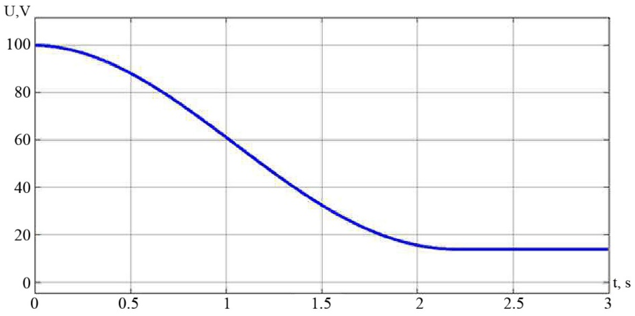
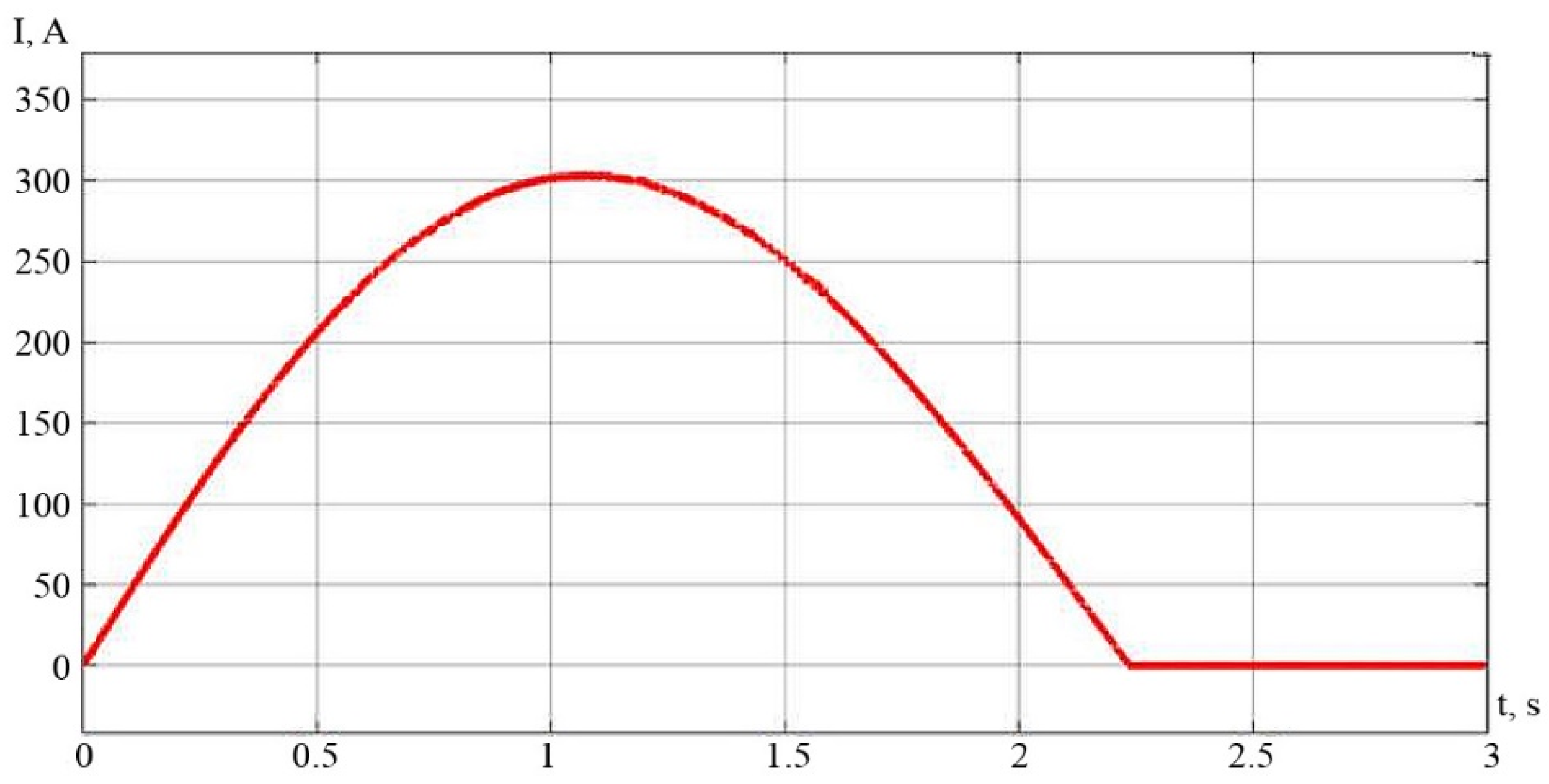
3.2. Checking the Possibility of Starting a Diesel Locomotive Using EDLC

As previous scientific studies have shown, supercapacitors [4,5,6] can be additional elements that provide energy when starting a diesel locomotive; they can work together with traditional starter batteries but also have advantages over them since their charge does not decrease significantly at low external temperatures.
One of the solutions to the problem of repeated starts can be to start the engine of the main diesel locomotive using a capacitor that has a double electric layer [43,44]. The start circuit is implemented on the basis of the booster circuit [45], and the operation and purpose of these are described in the second section.
The capacitor acts as a supercapacitor C2.1 with an internal resistance of R2 = 0.005 Ohm. The supercapacitor C2.1 has a capacitance of C = 5 F and an initial voltage of U = 100 V. The setting of the supercapacitor parameters is shown in Table 5.
To increase the current smoothly, an inductor L2 with a value of L = 0.1 H and a resistance of R2.1 equal to R = 0.005 Ohm were introduced into the circuit. The set parameters of the inductor L2 and resistance R2.1 are shown in Table 5.
The capacitor C2.2 is used to filter the system interference, whose capacitance is C = 0.1 F. The value of the parameters of the capacitor C2.2 is shown in Table 5. A VD2 diode blocks the load and the C2.2 capacitor in the key KM2 element at the right time.
The parameters of the VD2 diode and the KM2 key have the standard settings shown in Table 5.
The pulse width on PWM2 was chosen in such a way that the supercapacitor C2.1 would discharge as much as possible when the system was started. PWM2 settings are shown in Table 5. The pulse amplitude is 1, the pulse period is 0.001 s, and the pulse width is 30% (of the period).
Figure 10 shows the start-up scheme of the main diesel locomotive using a supercapacitor.
A feature of the proposed circuit is that the circuit contains PWM in its composition. The PWM pulse width was synchronized with the capacitance of the supercapacitor in such a way that the charge of the supercapacitor before starting the diesel was maximum to transfer this energy to start the diesel. The diode used in the circuit serves to block the capacitor and the load at the required times. Simultaneously, an increase in ESR was experimentally determined to cause a reduction in the service life of supercapacitors. Operating properly, KDES can withstand more than 500,000 charge/discharge cycles without changing the capacity, and their minimum service life reaches 10 years.
The graphs of the output of the starting circuit are shown in Figure 11 and Figure 12.
An analysis of the graphs of current and voltage dependences on time by the example of the supercapacitor indicates that the EDLC is capable of delivering energy only for 2.6 s. This is insufficient because the launch takes 15–20 s, and after 2.6 s, the voltage and current drop to zero, and there is no way to continue to rotate the crankshaft. In this regard, the joint use of batteries and EDLC in the system for starting the traction engine of a main diesel locomotive seems to be a productive solution [46].

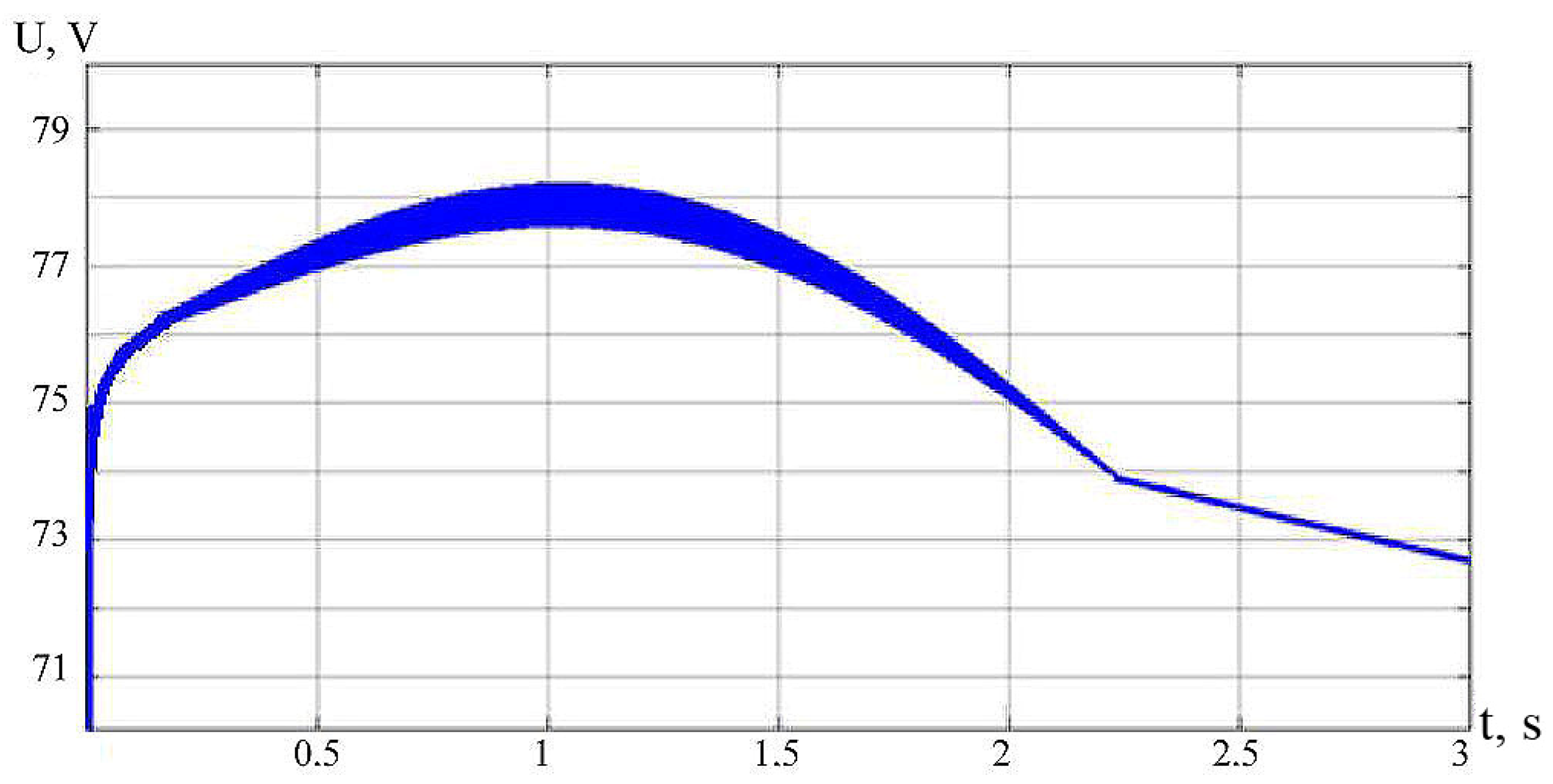
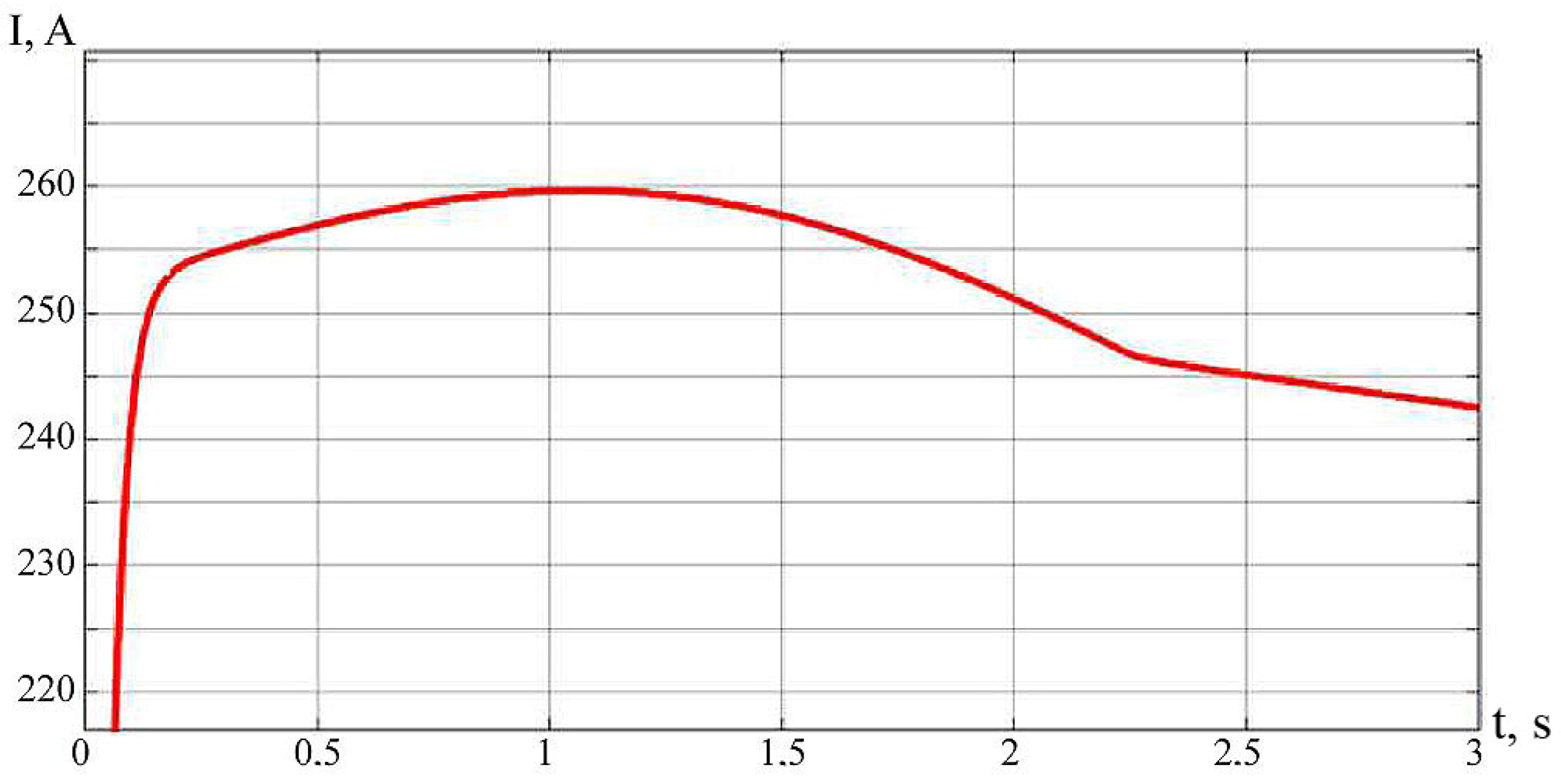
3.3. Modeling of the Diesel Locomotive Start-Up System Based on the Booster Stabilizer Scheme

To achieve the required results, the system for starting the internal combustion engine of the main diesel locomotive was modernized. A booster circuit was integrated into the standard launch system [47].
Figure 13 shows a starting scheme for a mainline diesel locomotive, designed on the basis of a booster stabilizer scheme and improved by the authors [48]. The parameters of all the circuit elements are similar to those of the previous circuits.
A feature of the upgraded circuit in the system designed for starting the internal combustion engine of the main diesel locomotive was the inclusion of an integrated booster circuit with an energy stabilizer. The proposed scheme, by adjusting the pulse width of the PWM, allowed the experiment to be conducted while using the supercapacitor as efficiently as possible. At the same time, the PWM tuning shows that the pulse width of almost half the pulses is effective in this circuit. Therefore, the ways to solve the parallel operation of two sections of batteries were proposed, but due to the wide variations in the parameters of such batteries, it was found to be unachievable (i.e., it is not possible to achieve equal voltage values on each of the two batteries). Therefore, it was proposed that supercapacitor could be used as a source of high pulsed energy, duplicating the main power source (a battery).
By setting the pulse width, PWM3 managed to use the C3.1 supercapacitor as efficiently as possible. Setting PWM showed that a pulse width of 30% is effective in this circuit. Figure 14 presents a graph of the voltage drop across the C3.1 supercapacitor over 3 s.
Figure 14 demonstrates that initially, the voltage on the supercapacitor C3.1 was U = 100 V, and during the start-up it began to drop rapidly, which indicates that the EDLC C3.1 supplies voltage to the system, thereby helping the GB battery to start the engine. In this case, the dependence of the current on time is shown in Figure 15.
An analysis of the output voltage and current graphs shown in Figure 16 and Figure 17, respectively, proves that the supercapacitor increases the voltage and current during the start-up. The voltage U = 78.2 V and the current I = 259.7 A of one battery and one supercapacitor are enough to make a guaranteed start in the diesel locomotive. Using such a system makes starting a diesel locomotive more reliable, faster, and more comfortable.
In this way, the start of the diesel locomotive can be guaranteed. The use of a supercapacitor in the starting system facilitates the start of a diesel engine and extends the battery life 2–4 times. At the same time, the proposed system does not require much maintenance; it is frost-resistant and safe to use during storage and operation. The used supercapacitor, on the basis of which the system is built, can be stored completely discharged and can be charged starting from a zero to operating voltage in a few minutes, depending on its capacity.
In the studies carried out, experimental studies of cold starts of the main diesel locomotive TG16M-001 were carried out together with the use of a storage battery and a supercapacitor. For experiments, a 2 × 40 × 7PzS560 battery manufactured by Tudor AGM 2 × 40 × 7PzS560 was chosen, which meets the following requirements: nominal voltage 80 V, capacity 560 Ah. The battery was kept at a low ambient temperature (the state of charge was ≈65%). Electric locomotive start-up time 8 s, diesel power 1550 hp (1140 kW). Ambient temperature −16 °C...−18 °C, ambient humidity 83%.
During the experimental start-up of a diesel locomotive, the experimental characteristics of the starting current and voltage were obtained and presented in Figure 18.
After checking the adequacy of the model to the system, which consisted of analyzing its proportionality relative to the system under study, as well as the equivalence of the system, the adequacy of the model was concluded to be more than 90%. This is a fairly good value for the adequacy since the model is not a complete representation of the system. In this case, the adequacy is violated due to the idealization of external conditions and operation modes, the exclusion of some parameters, and the neglect of a number of random factors. There is no information about external influences in the model; i.e., it does not take into account the electromechanical connection of the locomotive having mechanical units at low negative temperatures and during self-discharge of the battery.
An analysis of the output voltage and current graphs presented in Figure 18 is consistent with the simulation graphs shown in Figure 16 and Figure 17. This analysis confirms that the supercapacitor increases the voltage and current when starting, proving that the starter battery and supercapacitor system are able to start a diesel electric locomotive in a cold season at low temperatures. In case of such a system, starting a diesel locomotive is reliable and the installation of such combined modernized power system can be recommended in railway transport, especially in cold climates. At the same time, the proposed system does not require special care; it is frost-resistant and safe during storage and operation. At the same time, the used supercapacitor, which is the basis of the system, can be stored completely discharged and then be subsequently charged quickly, even at low temperatures.
Thanks to the results of this research, the authors managed to obtain new circuit solutions for starting diesel locomotives using a standard battery starter system and an effective electronic customizable capacitor battery control circuit. The novelty of the scheme proposed in this paper (Figure 13), for a system that started the internal combustion engine of a main diesel locomotive, was the inclusion in it of an integrated booster circuit of an energy stabilizer using PWM. In the proposed scheme, by adjusting the pulse width on the PWM, it was possible to use the supercapacitor as efficiently as possible. The novelty of using PWM is that the most efficient pulse width is one that is almost half the pulses.
In this study, there are several contrasts to the existing proposed options for launching diesel locomotives using a capacitor bank [17,18] in which the launch is carried out in two stages. In the existing options, the first stage corresponds to the power supply from a supercapacitor battery, and the second stage corresponds to the power supply from the battery [1]. In this study, meanwhile, it was proposed to carry out parallel inclusion in the starting system of both the battery and the supercapacitor. Moreover, both the simulation modeling and the physical experiments conducted were carried out at a battery charge level of 65% and at real low ambient temperatures down to −20 °C. This research is also novel compared to existing developments, in which the operation of the battery took place in more comfortable conditions and the battery was charged to 95–100%
The supercapacitor battery as part of the diesel locomotive start-up system made it possible to overcome the mechanical resistance to the starting crankshaft spin-up (1.5–2 s), which significantly reduces the peak current load on the standard battery at the initial start-up moment. The results of this study determined the effective aspects of using a supercapacitor, which consists of reducing the peak current load on a standard battery at the initial starting moment due to the maximum torque in the initial period of cranking the engine shaft; in increasing the service life of the system 1.5-fold; and a 1.5–2-fold decrease in the capacity of a regular battery which results in a decrease in cost. At the same time, it is not rational to completely abandon the use of the battery in the starting system at this point in time due to the constant load coming from the oil and fuel pumps, lighting devices, and air and water heating devices.
The data obtained in this study allow us to conclude that the most high-quality calculation of the values of the equivalent circuit parameters for the electric start circuit are necessary to determine the optimal value of the electric capacitance of the supercapacitor battery in the implementation of the synchronous start mode. It seems possible to perform on the volt-second and ampere-second characteristics of an unsuccessful start of a diesel engine from a supercapacitor.
The conducted studies have shown that the operating mode of the battery at the moment of starting has become gentler, and the value of starting currents set by the manufacturer has decreased by 1.5 times. Based on the locomotive start-up experiments and changes in the ESR of the supercapacitor, it can be argued that, with proper operation, supercapacitor batteries can withstand more than 500,000 charge/discharge cycles without changing their capacity, and their minimum service life reaches 10 years.
The presented plots of output voltage (Figure 16) and current (Figure 17) clearly show that the supercapacitor increases voltage and current at startup. At the same time, the value of voltage U and current I of the storage battery and supercapacitor is sufficient for a guaranteed start of the diesel locomotive, as tests have shown (Figure 18). With the help of such a system, the launch of a diesel locomotive is more reliable, faster, and more comfortable.
For clarity, the main differences between the parameters of the presented methodology for starting a diesel locomotive are shown in Table 6 [47].
Further work in this area involves modeling lithium-based batteries, as well as testing the proposed methodology in the field operating conditions of diesel locomotives.

4. Conclusions

-
The data obtained in this study make it possible to determine the most qualitative calculation of the values of the equivalent circuit parameters for the electric starting circuit, which is required to determine the optimal value of the electric capacitance of the supercapacitor battery when implementing the “cold” mode of starting the locomotive diesel, and can be completed when a storage battery and a battery of supercapacitors are combined;
-
The battery 2 × 40 × 7PzS560 made by JSC “Tudor AGM 2 × 40 × 7PzS560” was chosen as a prototype. It meets such requirements as the nominal voltage of 80 V and a capacity of 560 Ah;
-
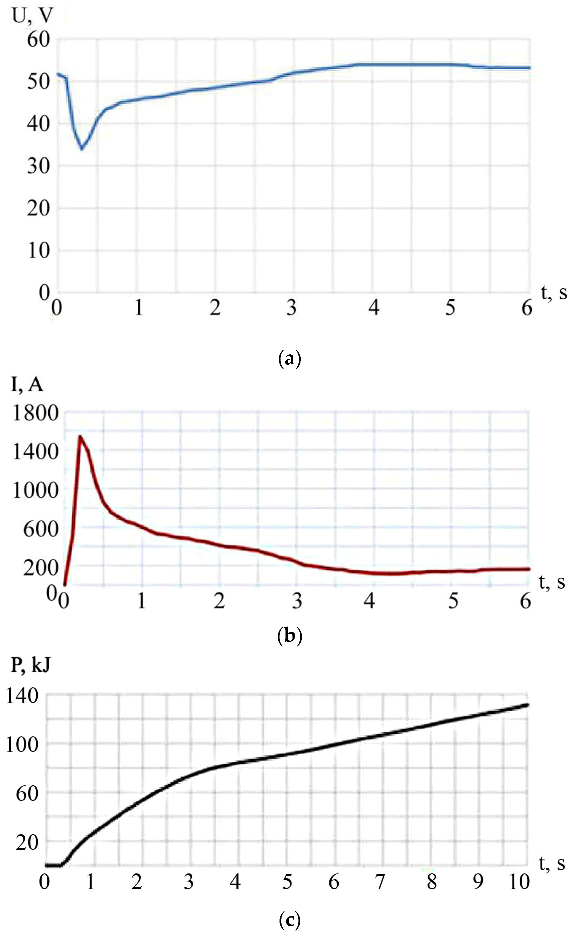
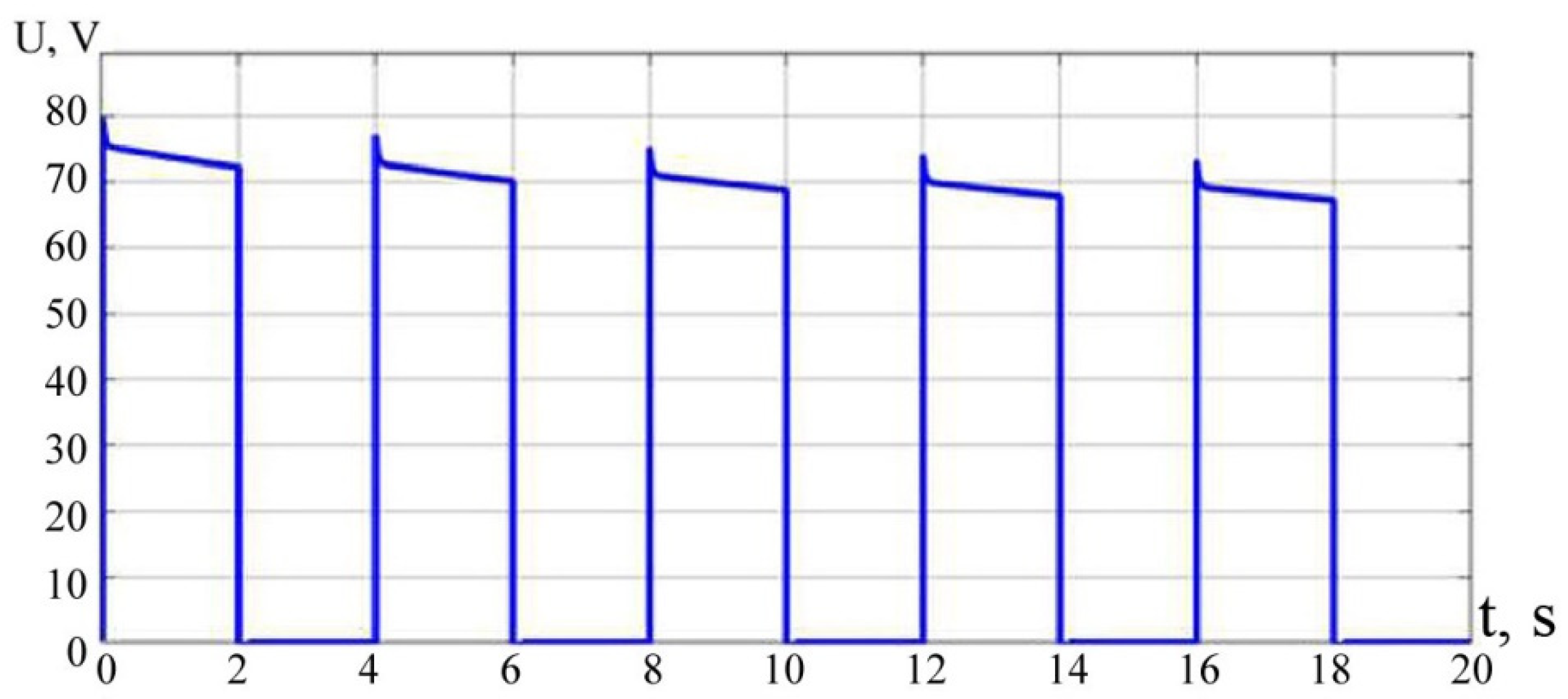
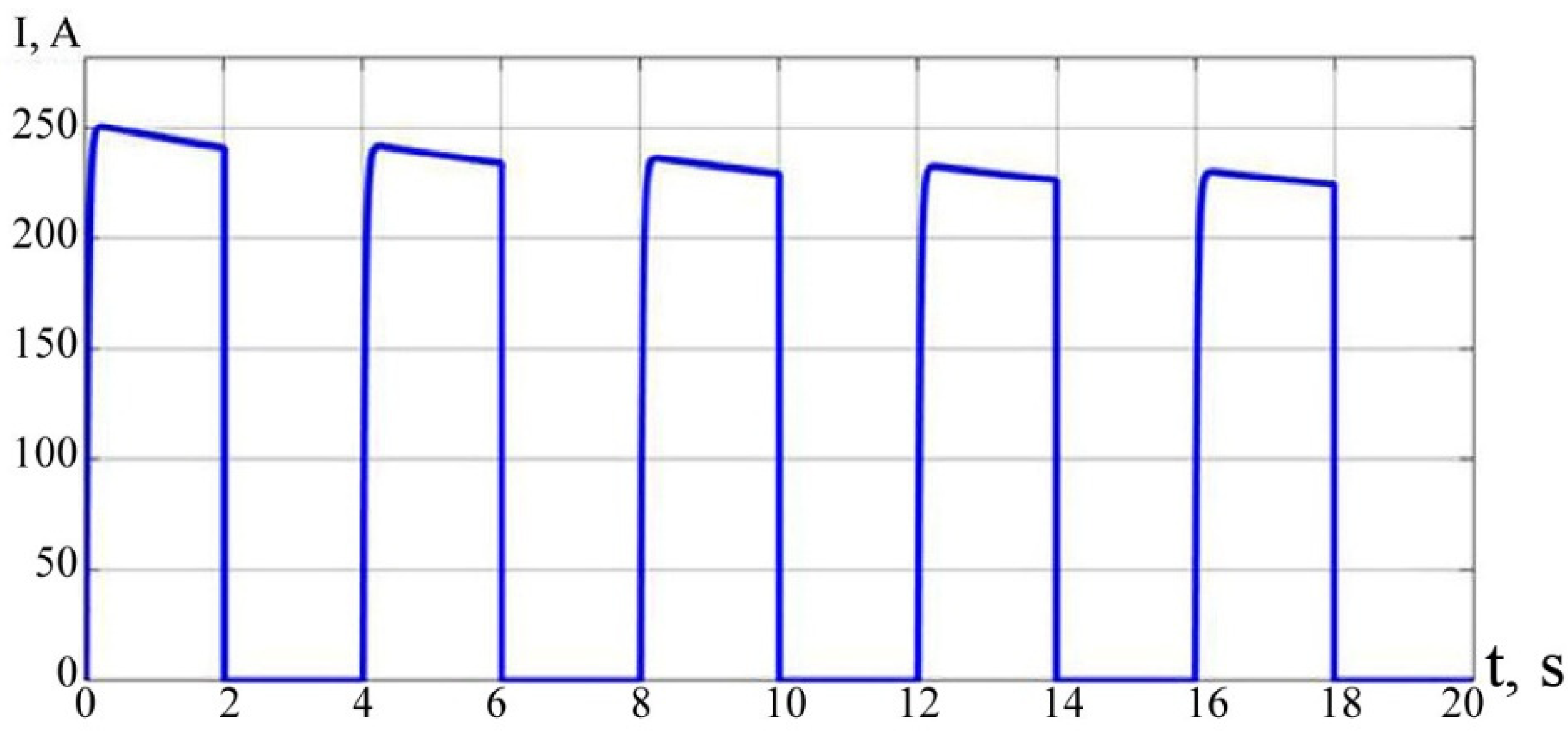
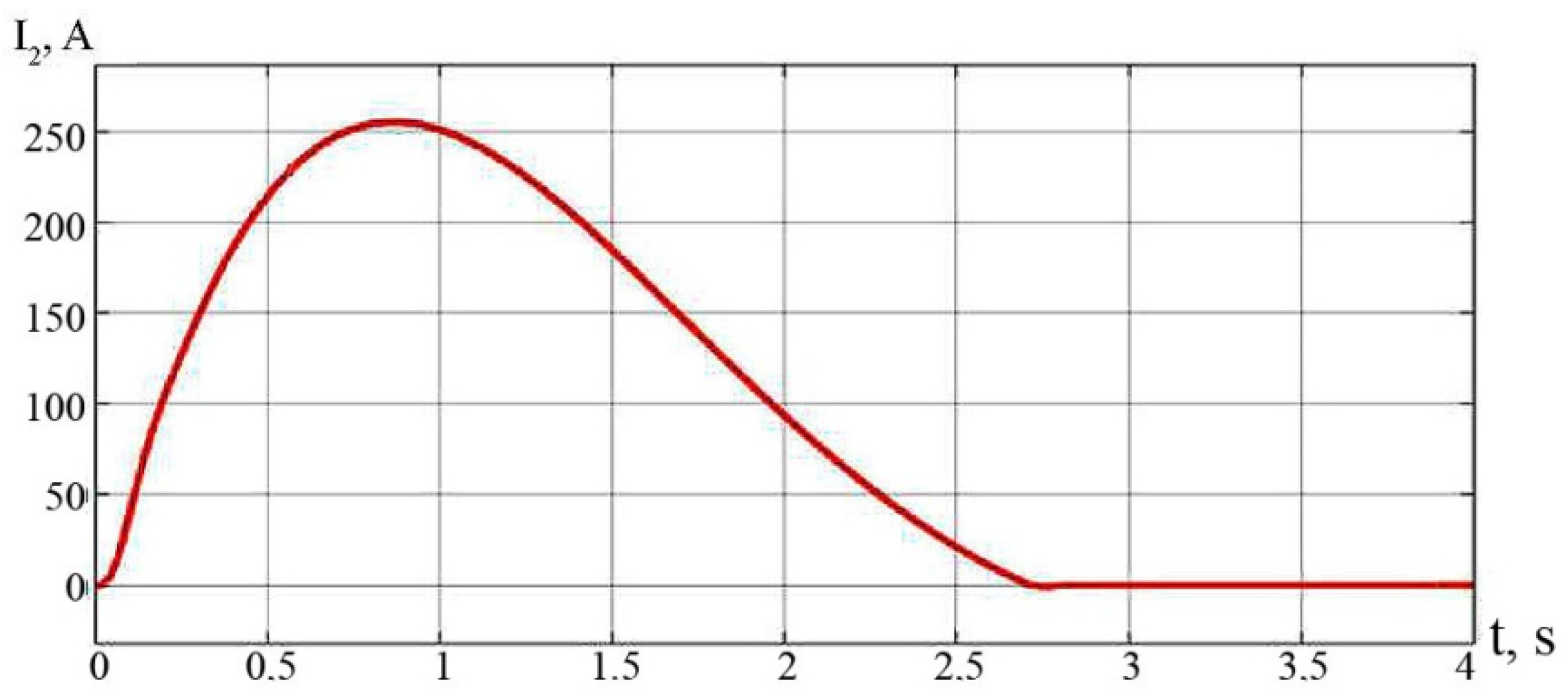
A typical system for starting a main diesel locomotive has been established to be inefficient during repeated starts. After the third attempt, starting a diesel engine is pointless, since the current and voltage values decrease by 3% of the initial value and they are not sufficient to spin the crankshaft. This study shows that it is impossible to use only EDLC in the launch system. Even though the supercapacitor produces the required current and voltage, its operating time is extremely insufficient. On average, the diesel locomotive starts up in 6–10 s, while the EDLC can deliver energy within 2.6 s;
-
Using the batteries in combination with EDLC in the diesel locomotive start-up system is proven to be the most effective option among the three considered methods; Applying a supercapacitor as part of the diesel locomotive start-up system allows the mechanical resistance to the starting crankshaft unwinding (1.5–2 s) to be overcome. This reduces the peak current load on the standard battery to the original one;
-
The diesel locomotive engine is allowed to restart, provided that there are intervals of 1–2 min, but the total number of repetitions should not exceed 10. The next attempt to start the diesel locomotive can be made no earlier than 6 h later, which increases the responsibility for such an important system as the starter;
-
In most cases, it is established that the start should be performed using rechargeable batteries as starter devices. Usually, powerful acid batteries are used as traction batteries;
-
A performance starter launch must take place no more than three times. The duration of each attempt should not exceed 15–20 s;
-
The rules set the range of temperatures within which the equipment must operate (above or equal to −45 °C and below or equal to +55 °C). In this case, the service life of the onboard starter battery is from 1 to 5 years; when the air temperature goes beyond the specified limits, the battery service life is halved;
-
During a starter start-up using a battery, unsuccessful launching attempts have been found due to insufficient amounts of energy supplied to the starter from the battery;
-
Ways have been proposed to solve the problem of the parallel operation of two sections of batteries, but due to the variations in the parameters of such batteries, it is not achieved (i.e., it is not possible to achieve equal voltage values on each of the 2 batteries). Using a supercapacitor as a source of high pulsed energy and duplication of the main power source (a battery) are proposed;
-
Short-term periods of exceeding the recommended values of the working voltage (more than 2.3–2.5 V) are allowed, but purely with prolonged overloads, while the risk of electrolyte decomposition increases. The range of ambient temperatures for the EDLC operation is set starting from −20 and ending with 70 °C, which exceeds the range of outdoor air temperatures for the battery operation;
-
An increase in ESR has been determined to cause a reduction in the service life of supercapacitors. Operating properly, EDLC can withstand more than 500,000 charge/discharge cycles without changing the capacity, and their minimum service life reaches 10 years;
-
A joint use of batteries and EDLC for starting a diesel locomotive is suggested. This solution is effective in the case of the locomotive traction engine’s starting system. The positive aspects of this method are the reduction in the peak current load on the standard battery at the initial start-up moment due to the maximum torque in the initial period of the engine shaft rotation, a 1.5-time increase in the system service life; a 1.5–2-time decrease in the capacity of a standard battery and, consequently, a decrease in its cost;
-
The simulation results can be applicable for different regions of countries having different climate conditions since the discharge of a starter battery is possible not only at low negative temperatures, but also during natural discharge of the battery due to its sulfation and an internal resistance increase.

Author Contributions

Conceptualization, N.V.M. and B.V.M.; methodology, R.V.K.; software, R.V.K.; validation, V.A.K. and V.V.K.; formal analysis, S.V.T.; investigation, Y.A.T.; resources, V.A.K. and V.V.K.; data curation, Y.A.T.; writing—original draft preparation, N.V.M. and B.V.M.; writing—review and editing, B.V.M., N.V.M. and R.V.K.; visualization, S.V.T. and N.A.Z. All authors have read and agreed to the published version of the manuscript.

Funding

This research received no external funding.

Data Availability Statement

The data presented in this study are available from the corresponding author upon reasonable request.

Conflicts of Interest

The authors declare no conflict of interest.

References

  1. Blinov, P.; Blinov, A. The Role of Diesel Locomotives Operating Modes in Simulating the Operation of Fuel and Control Equipment of Diesel Locomotives. In Networked Control Systems for Connected and Automated Vehicles; Springer: Cham, Switzerland, 2023. [Google Scholar] [CrossRef]
  2. da Silva Moraes, C.G.; Brockveld, S.L.; Heldwein, M.L.; Franca, A.S.; Vaccari, A.S.; Waltrich, G. Power Conversion Technologies for a Hybrid Energy Storage System in Diesel-Electric Locomotives. IEEE Trans. Ind. Electron. 2021, 68, 9081–9091. [Google Scholar] [CrossRef]
  3. Helen, L.; Vedaiyan, R.; Xavier, V.; Joy, J.; Jegatheesan, A.; Lakshmi, D.; Raj, J. Hybrid Bacterial Foraging Optimization with Sparse Autoencoder for Energy Systems. Comput. Syst. Sci. Eng. 2023, 45, 701–714. [Google Scholar] [CrossRef]
  4. Xiong, C.; Zhang, Y.; Xu, J. Kinetics process for structure-engineered integrated gradient porous paper-Based supercapacitors with boosted electrochemical performance. Nano Res. 2023, 16, 1–9. [Google Scholar] [CrossRef]
  5. Xiong, C.; Zhang, Y.; Ni, Y. Recent progress on development of electrolyte and aerogel electrodes applied in supercapacitors. J. Power Sources 2023, 560, 232698. [Google Scholar] [CrossRef]
  6. Zhang, Y.N.; Su, C.Y.; Chen, J.L. Recent progress of transition metal-based biomass-derived carbon composites for supercapacitor. Rare Met. 2023, 42, 769–796. [Google Scholar] [CrossRef]
  7. Xiong, C.; Yang, Q.; Dang, W.; Zhou, Q.; Jiang, X.; Sun, X.; Wang, Z.; An, M.; Nic, Y. A multifunctional paper-based supercapacitor with excellent temperature adaptability, plasticity, tensile strength, self-healing, and high thermoelectric effects. J. Mater. Chem. A 2023, 11, 4769–4779. [Google Scholar] [CrossRef]
  8. Peng, M.; Wang, L.; Li, L.; Peng, Z.; Tang, X.; Hu, T.; Yuan, K.; Chen, Y. Molecular crowding agents engineered to make bioinspired electrolytes for high-voltage aqueous supercapacitors. eScience 2021, 1, 83–90. [Google Scholar] [CrossRef]
  9. Yeom, K. Model predictive control and deep reinforcement learning based energy efficient eco-driving for battery electric vehicles. Energy Rep. 2022, 8, 34–42. [Google Scholar] [CrossRef]
  10. Wang, J.; Kontar, R.E.; Jin, X.; King, J. Electrifying High-Efficiency Future Communities: Impact on Energy, Emissions, and Grid. Adv. Appl. Energy 2022, 6, 100095. [Google Scholar] [CrossRef]
  11. Mamun, K.A.; Islam, F.R.; Haque, R.; Chand, A.A.; Prasad, K.A.; Goundar, K.K.; Prakash, K.; Maharaj, S. Systematic Modeling and Analysis of On-Board Vehicle Integrated Novel Hybrid Renewable Energy System with Storage for Electric Vehicles. Sustainability 2022, 14, 2538. [Google Scholar] [CrossRef]
  12. Jin, Z.; Li, D.; Hao, D.; Zhang, Z.; Guo, L.; Wu, X.; Yuan, Y. A portable, auxiliary photovoltaic power system for electric vehicles based on a foldable scissors mechanism. Energy Built Environ. 2022, in press. [CrossRef]
  13. Chao, P.-P.; Zhang, R.-Y.; Wang, Y.-D.; Tang, H.; Dai, H.-L. Warning model of new energy vehicle under improving time-to-rollover with neural network. Meas. Control 2022, 55, 1004–1015. [Google Scholar] [CrossRef]
  14. Kokourov, D.V.; Malozyomov, B.V. Algorithm for improving energy efficient wheel motor for electric vehicles. J. Phys. Conf. Ser. 2021, 2061, 012049. [Google Scholar] [CrossRef]
  15. Laadjal, K.; Cardoso, A.J.M. Estimation of Lithium-Ion Batteries State-Condition in Electric Vehicle Applications: Issues and State of the Art. Electronics 2021, 10, 1588. [Google Scholar] [CrossRef]
  16. Arango, I.; Lopez, C.; Ceren, A. Improving the Autonomy of a Mid-Drive Motor Electric Bicycle Based on System Efficiency Maps and Its Performance. World Electric. Veh. J. 2021, 12, 59. [Google Scholar] [CrossRef]
  17. Mei, J.; Zuo, Y.; Lee, C.H.; Wang, X.; Kirtley, J.L. Stochastic optimization of multi-energy system operation considering hydrogen-based vehicle applications. Adv. Appl. Energy 2021, 2, 100031. [Google Scholar] [CrossRef]
  18. Wu, X. Research and Implementation of Electric Vehicle Braking Energy Recovery System Based on Computer. J. Phys. Conf. Ser. 2021, 1744, 022080. [Google Scholar] [CrossRef]
  19. Istomin, S. Development of a system for electric power consumption control by electric rolling stock on traction tracks of locomotive depots. IOP Conf. Ser. Mater. Sci. Eng. 2020, 918, 012157. [Google Scholar] [CrossRef]
  20. Domanov, K.; Shatohin, A.; Nezevak, V.; Cheremisin, V. Improving the technology of operating electric locomotives using electric power storage device. E3S Web Conf. 2019, 110, 01033. [Google Scholar] [CrossRef]
  21. Debelov, V.V.; Endachev, D.V.; Yakunov, D.M.; Deev, O.I. Charging balance management technology for low-voltage battery in the car control unit with combined power system. IOP Conf. Ser. Mater. Sci. Eng. 2019, 534, 012029. [Google Scholar] [CrossRef]
  22. Widmer, F.; Ritter, A.; Duhr, P.; Onder, C.H. Battery lifetime extension through optimal design and control of traction and heating systems in hybrid drivetrains. eTransportation 2022, 14, 100196. [Google Scholar] [CrossRef]
  23. Liu, X.; Zhao, M.; Wei, Z.; Lu, M. The energy management and economic optimization scheduling of microgrid based on Colored Petri net and Quantum-PSO algorithm. Sustain. Energy Technol. Assess. 2022, 53, 102670. [Google Scholar] [CrossRef]
  24. Tormos, B.; Pla, B.; Bares, P.; Pinto, D. Energy Management of Hybrid Electric Urban Bus by Off-Line Dynamic Programming Optimization and One-Step Look-Ahead Rollout. Appl. Sci. 2022, 12, 4474. [Google Scholar] [CrossRef]
  25. Zhou, J.; Feng, C.; Su, Q.; Jiang, S.; Fan, Z.; Ruan, J.; Sun, S.; Hu, L. The Multi-Objective Optimization of Powertrain Design and Energy Management Strategy for Fuel Cell–Battery Electric Vehicle. Sustainability 2022, 14, 6320. [Google Scholar] [CrossRef]
  26. Pusztai, Z.; Korös, P.; Szauter, F.; Friedler, F. Vehicle Model-Based Driving Strategy Optimization for Lightweight Vehicle. Energies 2022, 15, 3631. [Google Scholar] [CrossRef]
  27. Graber, G.; Calderaro, V.; Galdi, V. Two-Stage Optimization Method for Sizing Stack and Battery Modules of a Fuel Cell Vehicle Based on a Power Split Control. Electronics 2022, 11, 361. [Google Scholar] [CrossRef]
  28. Davydenko, L.; Davydenko, N.; Bosak, A.; Bosak, A.; Deja, A.; Dzhuguryan, T. Smart Sustainable Freight Transport for a City Multi-Floor Manufacturing Cluster: A Framework of the Energy Efficiency Monitoring of Electric Vehicle Fleet Charging. Energies 2022, 15, 3780. [Google Scholar] [CrossRef]
  29. Zou, Y.; Sun, F.-C.; Zhang, C.-N.; Li, J.-Q. Optimal energy management strategy for hybrid electric tracked vehicles. Int. J. Veh. Des. 2012, 58, 307–324. [Google Scholar] [CrossRef]
  30. Ferrara, A.; Zendegan, S.; Koegeler, H.-M.; Gopi, S.; Huber, M.; Pell, J.; Hametner, C. Optimal Calibration of an Adaptive and Predictive Energy Management Strategy for Fuel Cell Electric Trucks. Energies 2022, 15, 2394. [Google Scholar] [CrossRef]
  31. Gim, J.; Kim, M.; Ahn, C. Energy Management Control Strategy for Saving Trip Costs of Fuel Cell/Battery Electric Vehicles. Energies 2022, 15, 2131. [Google Scholar] [CrossRef]
  32. Geng, S.; Schulte, T.; Maas, J. Model-Based Analysis of Different Equivalent Consumption Minimization Strategies for a Plug-In Hybrid Electric Vehicle. Appl. Sci. 2022, 12, 2905. [Google Scholar] [CrossRef]
  33. Martyushev, N.V.; Malozyomov, B.V.; Khalikov, I.H.; Kukartsev, V.A.; Kukartsev, V.V.; Tynchenko, V.S.; Tynchenko, Y.A.; Qi, M. Review of Methods for Improving the Energy Efficiency of Electrified Ground Transport by Optimizing Battery Consumption. Energies 2023, 16, 729. [Google Scholar] [CrossRef]
  34. Sun, B.; Gu, T.; Xie, M.; Wang, P.; Gao, S.; Zhang, X. Strategy Design and Performance Analysis of an Electromechanical Flywheel Hybrid Scheme for Electric Vehicles. Sustainability 2022, 14, 11017. [Google Scholar] [CrossRef]
  35. Sandrini, G.; Chindamo, D.; Gadola, M. Regenerative Braking Logic That Maximizes Energy Recovery Ensuring the Vehicle Stability. Energies 2022, 15, 5846. [Google Scholar] [CrossRef]
  36. Lu, Q.; Zhou, W.; Zheng, Y. Regenerative Braking Control Strategy with Real-Time Wavelet Transform for Composite Energy Buses. Machines 2022, 10, 673. [Google Scholar] [CrossRef]
  37. Mariani, V.; Rizzo, G.; Tiano, F.; Glielmo, L. A model predictive control scheme for regenerative braking in vehicles with hybridized architectures via aftermarket kits. Control Eng. Pract. 2022, 123, 105142. [Google Scholar] [CrossRef]
  38. Zou, X. Analysis of Slip rate Control Technology of Electric Vehicle Based on Sliding Mode Algorithm. J. Phys. Conf. Ser. 2022, 2254, 012034. [Google Scholar] [CrossRef]
  39. Liu, S.; Li, Z.; Ji, H.; Wang, L.; Hou, Z. A Novel Anti-Saturation Model-Free Adaptive Control Algorithm and Its Application in the Electric Vehicle Braking Energy Recovery System. Symmetry 2022, 14, 580. [Google Scholar] [CrossRef]
  40. Liu, C.; Zhang, K. Research on regenerative braking energy recovery strategy of electric vehicle. J. Phys. Conf. Ser. 2021, 2030, 012003. [Google Scholar] [CrossRef]
  41. Hensher, D.A.; Wei, E.; Liu, W. Battery electric vehicles in cities: Measurement of some impacts on traffic and government revenue recovery. J. Transp. Geogr. 2021, 94, 103121. [Google Scholar] [CrossRef]
  42. Caban, J. Technologies of Using Energy Harvesting Systems in Motor Vehicles—Energy from Suspension System. Eng. Rural. Dev. 2021, 20, 1470–1477. [Google Scholar] [CrossRef]
  43. Shchurov, N.I.; Dedov, S.I.; Malozyomov, B.V.; Shtang, A.A.; Martyushev, N.V.; Klyuev, R.V.; Andriashin, S.N. Degradation of Lithium-Ion Batteries in an Electric Transport Complex. Energies 2021, 14, 8072. [Google Scholar] [CrossRef]
  44. Henao-Muñoz, A.C.; Pereirinha, P.; Bouscayrol, A. Regenerative Braking Strategy of a Formula SAE Electric Race Car Using Energetic Macroscopic Representation. World Electr. Veh. J. 2020, 11, 45. [Google Scholar] [CrossRef]
  45. Shchurov, N.I.; Myatezh, S.V.; Malozyomov, B.V.; Shtang, A.A.; Martyushev, N.V.; Klyuev, R.V.; Dedov, S.I. Determination of Inactive Powers in a Single-Phase AC Network. Energies 2021, 14, 4814. [Google Scholar] [CrossRef]
  46. Isametova, M.E.; Nussipali, R.; Martyushev, N.V.; Malozyomov, B.V.; Efremenkov, E.A.; Isametov, A. Mathematical Modeling of the Reliability of Polymer Composite Materials. Mathematics 2022, 10, 3978. [Google Scholar] [CrossRef]
  47. Liu, H.; Lei, Y.; Fu, Y.; Li, X. Multi-Objective Optimization Study of Regenerative Braking Control Strategy for Range-Extended Electric Vehicle. Appl. Sci. 2020, 10, 1789. [Google Scholar] [CrossRef]
  48. Donatantonio, F.; Ferrara, A.; Polverino, P.; Arsie, I.; Pianese, C. Novel Approaches for Energy Management Strategies of Hybrid Electric Vehicles and Comparison with Conventional Solutions. Energies 2022, 15, 1972. [Google Scholar] [CrossRef]
Figure 1. Diesel electric locomotive of the TG16M-001 type.
Energies 16 03909 g001
Figure 2. Schematic of the diesel electric locomotive showing the main parts of TG16M-001.
Energies 16 03909 g002
Figure 3. Dependence of the voltage of the batteries in the starter mode on the electrolyte temperature.
Energies 16 03909 g003
Figure 4. Curves of starting the diesel engine of the TG16M-00 diesel locomotive 1: (a) voltage, (b) current and (c) power.
Energies 16 03909 g004
Figure 5. EDLC structure.
Energies 16 03909 g005
Figure 6. Time dependence of the voltage.
Energies 16 03909 g006
Figure 7. Regular system for starting a diesel locomotive.
Energies 16 03909 g007
Figure 8. Dependence of the starting voltage on time during repeated starts.
Energies 16 03909 g008
Figure 9. Dependence of the starting current on time during repeated starts.
Energies 16 03909 g009
Figure 10. System for starting a diesel locomotive using EDLC.
Energies 16 03909 g010
Figure 11. Dependence of the voltage at the output of the circuit on time.
Energies 16 03909 g011
Figure 12. Dependence of the current at the output of the circuit on time.
Energies 16 03909 g012
Figure 13. Advanced Scheme of starting a locomotive engine using a supercapacitor.
Energies 16 03909 g013
Figure 14. Dependence U(t) on the C3.1 supercapacitor.
Energies 16 03909 g014
Figure 15. Dependence I(t) on the C3.1 supercapacitor.
Energies 16 03909 g015
Figure 16. Dependence of the voltage of the starter on time.
Energies 16 03909 g016
Figure 17. Dependence of the current of the starter on time. The maximum current Imax is 303 A, which corresponds to the starter current.
Energies 16 03909 g017
Figure 18. Experimental dependences of the voltage (a) and current (b) on time.
Energies 16 03909 g018
Table 1. Technical characteristics of EDLC.
ManufacturerItem
Type
Capacity, FRated Voltage, VStore Energy, W∙hInternal Resistance, mOh mWeight, kgSpecific Energy Intensity, W∙h/kgSpecific Power, kW/kg
Ynaskopower cell4002.70.410.250.1053.83.3
VartaY120012002.71.20.470.34.1n/a
YECNL 1001002.70.100.170.0234.42.5
NesscapESHSR-2000C0-002R7A520002.72.0250.330.395.26.7
PanasonicHL50502.70.050.150.0192.71.4
Table 2. Technical characteristics of lead-acid batteries.
ManufacturerItem TypeCapacity, AhRated Voltage, VStarter Current, AWeight, kg
Mutlu Silver Evolution 55(450)55EH-150G-y215096300648
VartaY32TN-450-U245064n/a1050
Tudor AGM″2 × 40 × 7PzS56056080n/a1482
Hawker Perfect Plus80V 6PzS93080n/a2192
KomatsuFB15EXF 24 × 6P7042048n/a646
Table 3. Specifications of the Battery Tudor (AGM 2 × 40 × 7PzS560).
Capacity, AhRated Voltage, VWeight, kg
560801482
Table 4. Settings of the parameters of the elements of the standard diesel locomotive start system.
ParameterValue
Lead-acid battery GB1
TypeLead-Acid
Nominal voltage80 V
Rated capacity56Ah
Initial state-of charge50%
Battery response time30 s
Switching key KM1
Internal resistance Ron0.001 Ohms
Initial state (0 for ‘open’, 1 for ‘closed’)0
Snubber resistance Rs105 Ohms
Snubber capacitance Cs0 F
Pulse width generator PWM1
Pulse typeTime based
Time (t)Use simulation time
Amplitude1
Period4 s
Pulse Width50% of period
Phase delay0 s
Starter-generator R1.2
Branch typeRL
Resistance0.3 Omhs
Inductance0.01 H
Diode VD1
Resistance Ron0.001 Ohms
Inductance Lon0 H
Forward voltage Vf0.4 V
Initial current Ic0 A
Snubber resistance Rs500 Ohms
Snubber capacitance Cs250∙10−9 F
Table 5. Settings of the parameters of the elements of the standard diesel locomotive start system.
ParameterValue
Supercapacitor C2.1
Brunch TypeC
Capacitance5 F
Set the initial capacitor voltageYes
Capacitor initial voltage100 V
Internal resistance of the supercapacitor C2.1
Brunch TypeR
Resistance0.005 Omhs
Inductor L2
Brunch typeL
Inductance0.1 H
Resistor R2.1
Branch typeR
Resistance0.005 Omhs
Capacitor C2.2
Branch typeC
Capacitance0.1 F
Diode VD2
Resistance Ron0.001 Ohms
Inductance Lon0 H
Forward voltage Vf0.4 V
Initial current Ic0 A
Snubber resistance Rs500 Ohms
Snubber capacitance Cs250∙10−9 F
Switching key KM2
Internal resistance Ron0.001 Ohms
Initial state (0 for ‘open’, 1 for ‘closed’)0
Snubber resistance Rs105 Ohms
Snubber capacitance Cs0 F
Pulse width generator PWM2
Pulse typeTime based
Time (t)Use simulation time
Amplitude1
Period0.001 s
Pulse Width30% of period
Phase delay0 s
Table 6. Settings of the parameters of the elements of the standard diesel locomotive start system.
ParametersStart-Up Control Scheme for a Diesel Locomotive Based on a Pulse-Width Modulator (This Development)Diesel Locomotive Start-Up Control Scheme Based on Analog Electrical Engineering
1.Type of scheme for starting the internal combustion engine of a main diesel locomotive.Integrated booster circuit of the energy stabilizer using PWM.Relay-contactor control principle
2Ability to adjust the width of the current pulseYes, due to PWMNo, the charge current is rigidly set
3The ability to adjust the width of the current pulse when the supercondenser is chargedYesNo
4The inclusion scheme of the supercondenser in the starting systemSynchronously with batterySequentially, after the discharge of the battery
5The minimum necessary level of charge of the battery for starting (at −20 °C), %65
6External temperature at 100% probability of starting a diesel locomotive with a full charge of the battery, °C,below −25above −7
7Possible number of attempts to start the diesel locomotive (required values of starting current and voltage are saved)3 at −20 °C1 at −7 °C
8Starter battery capacity, Ah560550
9Supercapacitor capacitance, F55
Disclaimer/Publisher’s Note: The statements, opinions and data contained in all publications are solely those of the individual author(s) and contributor(s) and not of MDPI and/or the editor(s). MDPI and/or the editor(s) disclaim responsibility for any injury to people or property resulting from any ideas, methods, instructions or products referred to in the content.

