Review

A Comprehensive Review of the Oil Flow Mechanism and Numerical Simulations in Shale Oil Reservoirs

1
Key Laboratory for Mechanics in Fluid Solid Coupling Systems, Institute of Mechanics, Chinese Academy of Sciences, Beijing 100190, China
2
School of Engineering Science, University of Chinese Academy of Sciences, Beijing 100049, China
3
Research Institute of Petroleum Exploration and Development, PetroChina, Beijing 100083, China
4
Department of Oil and Gas Technologies, Perm National Research Polytechnic University, 614990 Perm, Russia
*
Author to whom correspondence should be addressed.
Energies 2023, 16(8), 3516; https://doi.org/10.3390/en16083516
Submission received: 8 February 2023 / Revised: 12 March 2023 / Accepted: 10 April 2023 / Published: 18 April 2023

Abstract

:
The pore structure of shale oil reservoirs is complex, and the microscale and nanoscale effect is obvious in the development of shale oil reservoirs. Understanding the oil flow mechanism in shale reservoirs is essential for optimizing the development plan and enhancing the recovery rate of shale oil reservoirs. In this review, we briefly introduce the occurrence status of shale oil and shale oil flow in the inorganic matrix and the organic matrix (including the shrinkage of kerogen, oil diffusion in kerogen, oil transport in the organic pore channels, coupling of diffusion, and fluid transport in the organic matrix). Then, the shale oil microflow simulation and a coupling model of double-porous media for microflow and macroflow in the production process of shale oil are discussed. Finally, we summarize the main conclusions and perspectives on the oil flow mechanism and numerical simulations in shale oil reservoirs. An accurate description of shale oil occurrence status and shale oil flow in the inorganic and organic matrices is crucial for the numerical simulation of shale oil reservoirs. It can provide a basis and reference for the future directions of shale oil flow and numerical simulations during the development of shale oil reservoirs.

1. Introduction

The US has achieved energy independence through the shale oil and gas revolution, and the US Energy Information Administration (EIA) estimated that, in 2021, approximately 2.64 billion barrels (or approximately 7.23 million barrels per day) of crude oil were produced directly from tight oil resources in the United States. This equated to approximately 64% of the total US crude oil production in 2021 [1], while China’s foreign dependence on crude oil in 2020 was as high as 73.5%, far exceeding the 50% safety alert line [2]. China’s energy crisis urgently needs to be addressed. Zhao et al. [3] estimated that the recoverable resources of shale oil with low–medium maturity of China’s continental shale oil is approximately (700–900) × 108 t. China’s shale oil resources have great potential, and the efficient recovery of shale oil is of great significance for China’s energy independence and national security.
Shale oil is liquid crude oil or condensate oil that occurs in shales or hard rock masses, unlike crude oil in the fine sand of ordinary oil fields, which cannot be self-injected with the underground pressure [4,5,6]. The permeability of shale oil reservoirs is extremely low, and the shale oil flow in nanoscale pores is different from that in macroscopic conditions. The complexity of shale oil flow is exacerbated by the surface effects, flow diffusion, viscosity effects, slip effects, and network structures of the topological features in nanostructures [7,8], which result in the inability of the Darcy and Navier–Stokes equations to accurately describe the fluid flow behavior [9]. In recent years, many scholars have considered the microscopic effects in the description of the shale oil flow mechanism by introducing the apparent permeability to modify the Darcy equation [10,11,12,13,14]. This correction often takes into account the presence of liquid slip and viscosity/density inhomogeneity in the contact part of the oil with the solid wall. Theoretical models usually simplify the shale pore space into cylindrical nanotubes and divide the flow of shale oil in the pore space into different regions: the near-wall region and bulk region. However, this simulation simplifies the roughness and complexity of shale nanopore surfaces, ignores the specific processes of molecular interactions between solid–liquid interfaces, and does not consider the multicomponent nature of shale oil. In recent years, many researchers have used numerical simulation methods [15,16,17] to build more realistic models of shale oil flow, which fully consider the effects of various microscopic factors on the flow mechanism.
Due to the complex pore structure characteristics of shale rocks, experimental studies of shale oil flow mechanisms take a long time and require many measurement instruments [18,19]. However, if the study is combined with numerical simulation techniques, it can both improve efficiency and theoretically explain the shale oil flow mechanism. At the microscopic level, molecular dynamics simulation (MDS) can simulate the fluid–solid molecular interactions at the molecular scale [20,21,22,23,24,25,26], and the lattice Boltzmann method (LBM) provides a bridge from the microscopic to the macroscopic level for shale oil flow and is suitable for dealing with flow problems in complex pore structures [27,28,29,30]. A pore network model (PNM) replaces the pore structure of the real core with a simplified network model and uses percolation theory as the controlling equation of the fluid flow, which can efficiently simulate the percolation process of shale oil [31,32,33]. From a macroscopic point of view, hydraulic fracturing technology is used to improve the overall permeability of the reservoir and, thus, increase the recovery rate of shale oil. The flow of shale oil in hydraulic fractures follows Darcy’s law. In addition, numerical simulation methods commonly used for hydraulic fracture expansion are the extended finite element method (XFEM) [34,35,36], displacement discontinuity method (DDM) [37,38,39,40,41,42], and discrete element method (DEM) [43,44,45]. By establishing a mathematical model of coupled shale oil microflow and macroflow, the shale oil production process can be simulated more realistically and accurately, and the influence of various parameters on shale oil production can be studied.
In this study, we review the recent advances and the occurrence status of shale oil and shale oil flow in the inorganic matrix and the organic matrix, such as shrinkage of kerogen, oil diffusion in kerogen, oil transport in the organic pore channels, coupling of diffusion, and fluid transport in the organic matrix. Then, the shale oil microflow simulation and the reservoir numerical simulation method of shale oil are analyzed. Finally, we summarize the main conclusions and perspectives of the oil flow mechanism and numerical simulation in shale oil reservoirs.

2. Oil Flow Mechanism in Shales

Shale oil is lodged in the micropores and nanopores of shale rocks, and the Knudsen number (Kn) is a very important parameter of the fluid flow at the microscale and nanoscale. Roy et al. [10] divide the fluid flow into four regions via Knudsen number, as shown in Figure 1. Due to the small average free range of shale oil molecules, many scholars believe that the Knudsen number of shale oil flowing in nanopores is Kn < 0.1; therefore, the current study regarded the flow of shale oil in nanopores as following the continuity assumption [30,46]. However, actual shale oil flow is higher than the value calculated using the traditional Darcy’s law and continuity assumption because diffusion and slip phenomena, etc., need to be considered in such nanopores [12,47,48]. Some scholars are now correcting the traditional Darcy’s formula by introducing the apparent permeability [13,49].

2.1. Shale Oil Occurrence Status

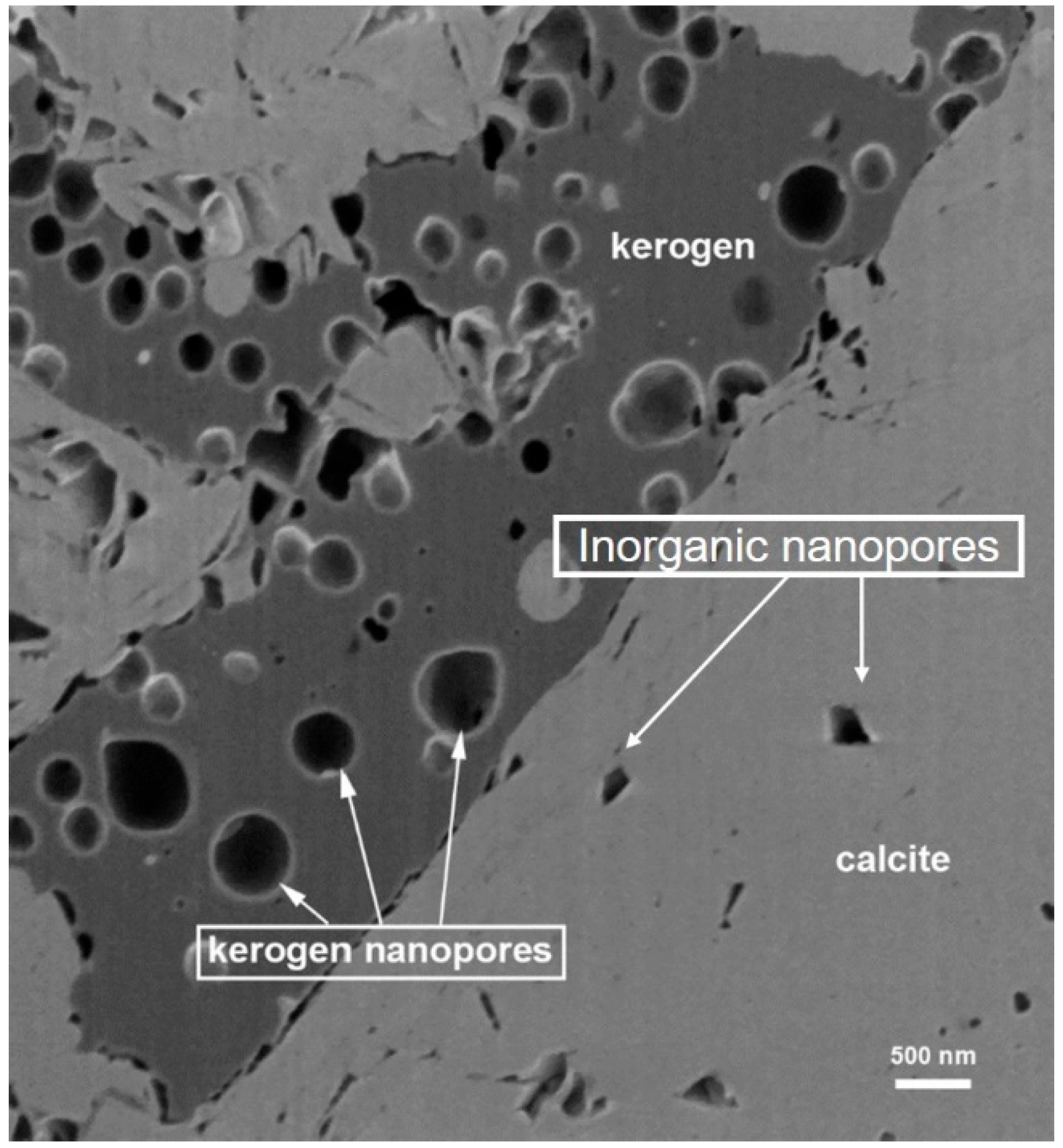
Organic matter in shale can be divided into free state, adsorbed state, and dissolved state [50,51]. Generally speaking, free oil is mainly composed of light hydrocarbon components with good fluidity, mainly in the pore joints, microfractures, layer interstices, and matrix pores with a relatively large pore throat diameter [52]. Adsorbed oil is mainly composed of medium–macromolecule components with poor mobility, mainly by physical adsorption and noncovalent bonding chemisorption on the surface of rock minerals and inside and outside the rigid macromolecular skeleton of the kerogen [53,54], primarily in organic pores, pyrite intergranular pores, and clay mineral intergranular pores [55]. Dissolved oil comes mostly in the form of medium–small molecule fractions, mainly in the form of the small molecule mobile phase enveloped by the internal network structure of kerogen, as well as in the form of asphaltene and residual dissolved water [56]. After the generation of hydrocarbons, residual hydrocarbons are reabsorbed into the kerogen skeleton, which causes the volume expansion of kerogen [57], and this part of the soluble organic matter is mainly stored in the kerogen macromolecular meshwork, as shown in Figure 2. The relative solubility of the different compounds in petroleum varies in kerogen, indicating that kerogen retains different hydrocarbon components differently [58].
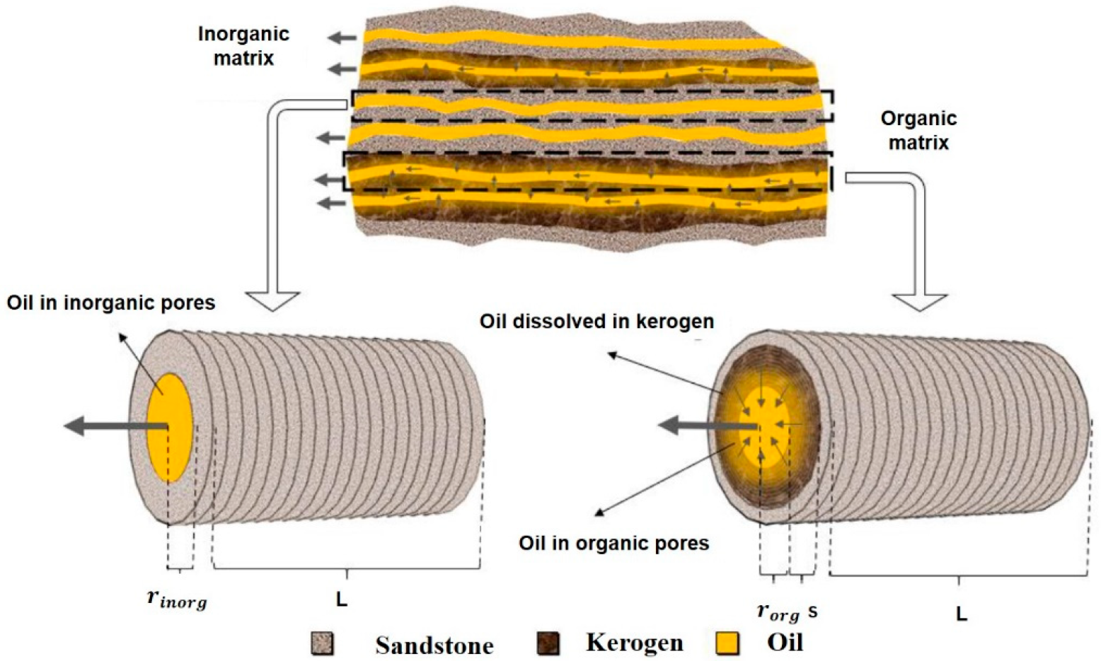
Based on the capillary bundle model, Li [48] established the fugacity and percolation state of shale oil in shale reservoirs, and he used large pore size capillaries to represent inorganic pores and a small pore size to represent organic pores, as shown in Figure 3. The yellow color represents free shale oil, the light gray color represents an inorganic sandstone reservoir, and the dark gray color represents kerogen. When mining causes a decrease in the pressure on one side of the reservoir, the free shale oil in the pore will flow to the left side due to the expansion of the shale skeleton and fluid. As this flow proceeds, the shale oil content in the organic pore decreases, and the concentration of shale oil inside kerogen increases, which constitutes the wall surface of the organic pore. The concentration of shale oil inside kerogen is higher due to the concentration difference, thus causing shale oil to diffuse from the inside of kerogen to the organic pore. When shale oil enters other organic pores, some of the shale oil diffuses back into kerogen due to the complex interactions between the shale oil molecules and kerogen wall surface. The above process reflects the flow state of shale oil in shale.
Shale pores are divided into organic and inorganic pores, as shown in Figure 4, and both hydrocarbons and water can flow in both types of pores [59,60]. The wettability of oil and water in the two pores is different due to their different compositions, and in organic pores, the wettability also changes with the thermal maturity of the casein, which has a significant effect on fluid flow in organic matter [61].

2.2. Shale Oil Flow in the Inorganic Matrix

In inorganic pores, due to the differences in energy, shale oil flow will follow Darcy’s law and the continuity equation. In a one-dimensional problem, the governing equation of the shale oil flow can be described as follows:
u i n o r g = 1 μ k i n o r g 𝛻 p
ϕ i n o r g ρ f t = 𝛻 ρ f u i n o r g
where u i n o r g is the velocity of the fluid in inorganic pores; μ is the fluid viscosity; k i n o r g is the inorganic permeability; p is the reservoir pressure; ϕ i n o r g is the inorganic porosity; and ρ f is the fluid density.
Li [41] obtained the following equation based on the above equation through a series of derivations:
ϕ i n o r g ρ f c f + ϕ i n o r g o ϕ i n o r g c r p t = x ρ f μ 0.01792 r i n o r g 2 ϕ i n o r g 2 p x
where r i n o r g is the characteristic radius of the inorganic pore; c f is the fluid compression coefficient; p 0 is the initial pressure; ρ f o is the initial density; c r is the compression coefficient of the inorganic matrix; and ϕ i n o r g o and p 0 are the initial porosity and initial pressure, respectively.
In addition, he believed that the inorganic pore cross-sectional area is proportional to the porosity and can be expressed as follows:
r i n o r g 2 = r i n o r g o 2 ϕ i n o r g ϕ i n o r g o
where r i n o r g o is the initial inorganic pore radius. The numerical solution of shale oil flow in inorganic pores can be obtained by integrating Equation (4) into Equation (3), and then the numerical solution of shale oil flow in inorganic pores can be obtained by discretization and constructing the iterative solution format of the above equation.
The reservoir extraction process often contains water intrusion, and the presence of a water phase makes a big difference in the flow state of oil in inorganic pores. Li et al. [63] considered oil slippage at the solid–oil boundary in inorganic pores under dry conditions, and water slippage was considered at the solid–water boundary during water–oil two-phase flow. An analytical model of oil–water two-phase flow is provided, as shown in Figure 5. The relative permeability curves of oil–water two-phase flow in inorganic pores were obtained.
Huang et al. [64] investigated the effect of solid–liquid–gas three-phase flow in the shale oil production process via the numerical simulation method. In multiphase flow, the flow characteristics are usually characterized by relative permeability, and wettability is an important parameter affecting the relative permeability. In the study, they found that the oil–water contact angle and oil–gas contact angle in inorganic matter have significant effects on production and that the relative permeability of inorganic pores is the main factor controlling the total shale oil production, as shale oil often passes through inorganic pores before flowing into the fractures of hydraulic fracturing due to the dispersion of organic matter.

2.3. Shale Oil Flow in the Organic Matrix

Shale oil in organic matter is shale oil dissolved in the kerogen and shale oil endowed in the nanoscale organic pores of the kerogen. The flow of shale oil in an organic matrix is different from that in an inorganic matrix, mainly because the permeability of an organic matrix is much lower than that in an inorganic matrix, and the oil flow in an organic matrix is coupled with diffusion, which does not occur in an inorganic matrix [65]. Considering the multiple factors that affect the flow of shale oil in organic pores and their complexity, the Darcy permeability in the traditional sense needs to be revised. Xu et al. [49] developed a two-fluid system model based on MDS data to calculate the oil flow in a single nanopore and established the stochastic apparent permeability model to facilitate engineering calculations. Many researchers are also currently characterizing the flow of shale oil in shale porous structures by introducing apparent permeability to characterize all influencing factors. In order to have a more realistic and clear understanding of the mechanism of shale oil flow in organic pores, many scholars have studied oil flow in organic matter through experiments and numerical simulations in recent years.
In organic matter, shale oil flows for two different reasons: (1) diffusion due to the differences in concentrations; (2) fluid transport due to the differences in pressure. Correspondingly, they will result in different equations of flow states.

2.3.1. Shrinkage and Expansion of Kerogen during Shale Oil Flow

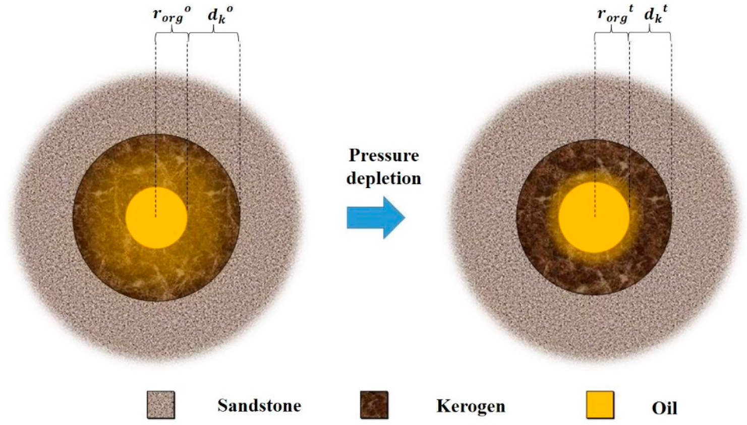
Kerogen refers to all oil-forming and coal-forming organic materials, and it swells when it is filled with hydrocarbon molecules and shrinks as hydrocarbon is desorbed. Sang et al. [62] found that 6% to 55% of the oil was in organic matter when the shale samples were saturated with shale oil by single-phase vacuum-imbibition tests on 20 shale samples and that 50% to 90% of this oil deposited in organic matter was ad-/absorbed in kerogen, where the absorbed oil was dissolved in the kerogen skeleton, while adsorbed oil was oil adsorbed on the surface of the kerogen; therefore, absorbed oil does not flow as easily as adsorbed oil. When the shale oil flows in the shale, part of the oil enters the organic pore (i.e., the kerogen pore), and this part of the oil will be absorbed oil and adsorbed oil in the kerogen matrix, resulting in a reduction of the organic pore size, as shown in Figure 6. In addition, when the well has been producing for some time, the decrease in the formation pressure leads to the desorption of hydrocarbons from the surface of the kerogen and shrinkage of the kerogen, which in turn leads to an increase in the pore size of the organic matter, as shown in Figure 7. In this process, the contraction and swelling of kerogen corresponds to the decrease and increase in the organic pore permeability.
Based on the assumption that the volume expansion of the kerogen caused by adsorption is proportional to the amount of dissolved oil in the kerogen [66], Li [48] derived the numerical iterative algorithm for calculating the pore size of organic matter after the shrinkage of kerogen.

2.3.2. Oil Diffusion in Kerogen

The Knudsen number of shale oil flowing in nanopores is considered to be less than 0.1, and the effects of Knudsen diffusion and surface diffusion are generally not considered. However, when shale oil flows in kerogen, the shale oil dissolved in the kerogen may be diffused by the concentration difference. Moreover, in the experiments conducted by Sang et al. [62], while performing the process of restoring the saturation of shale oil in kerogen via vacuum suction and expansion, it was found that the amount of oil inhaled was greater than the original pore capacity of kerogen, which means that the shale oil underwent adsorption and dissolution during the flow in the pores of kerogen and the diffusion behavior of shale oil into the organic matter wall.
In addition, Li [48] argues that in the computational model the oil in the kerogen will diffuse into the pores of the kerogen due to the concentration difference during the flow of shale oil. Considering how time dependent the diffusion of dissolved oil is, he argues that the diffusion in the kerogen during the flow of shale oil is in accordance with Fick’s second law and provides the controlling equation for the radially unsteady expansion of shale oil in the kerogen as follows:
c t = 1 r r D r c r = D r c r + D 2 c r 2
where c is the concentration of dissolved oil; r is the layer thickness of kerogen in the shale matrix; and D is the diffusion coefficient.
Considering the diffusion behavior of shale oil with the organic matter wall of the kerogen, it is equivalent to introducing a source/sink term in the actual model calculation process. Moreover, the diffusion of shale oil corresponds to the contraction and expansion behavior of the aforementioned kerogen, and the change in the organic matter porosity should be considered at this time, which also reflects the complex coupling between multiple variables in the shale oil flow process.

2.3.3. Oil Transport in the Organic Pore Channels

We refer to the flow of shale oil in organic matter driven by pressure as the transport of oil in organic pore channels. Since many strong interactions occur between shale oil molecules in organic pore and organic matter wall molecules, such as electrostatic force, van der Waals force, and hydrogen bonds [65]. As a result, an increase in resistance to the flow of shale oil and impedance of the flow transport of oil, the presence of adsorption layers in the part of the oil in contact with the pore wall, the presence of velocity slip, and inhomogeneous phenomena of fluid viscosity/density are usually considered. Su et al. [67] summarized four theoretical models to characterize the flow of a single nanopore, which considered the effect of solid–liquid intermolecular interaction forces on the flow, and finally characterized the flow of shale oil in the pore by calculating the modified Darcy permeability.
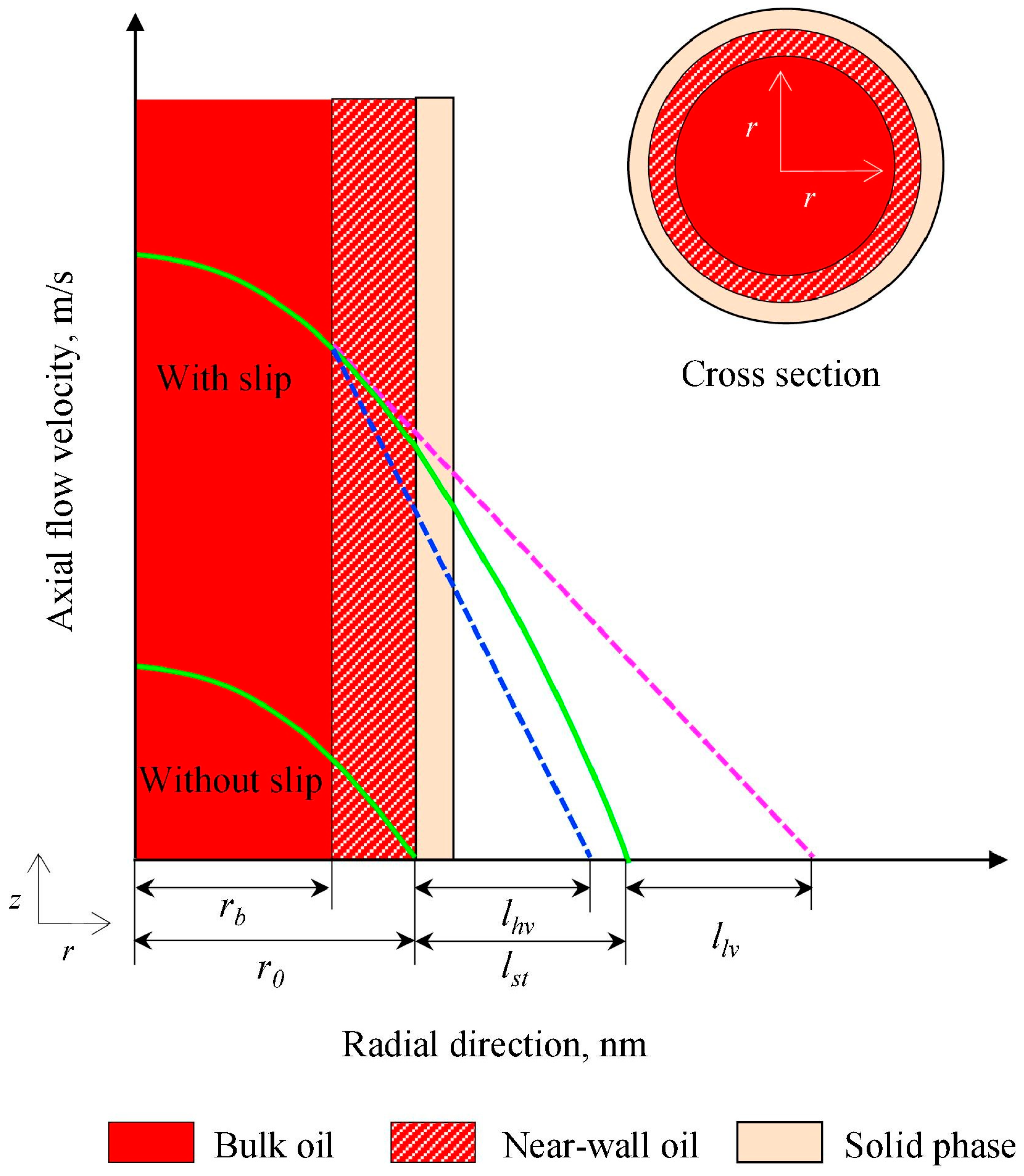
Zhang et al. [30] developed a single-phase flow nanopore model in a single nanopore and the nanoporous shale, as shown in Figure 8.
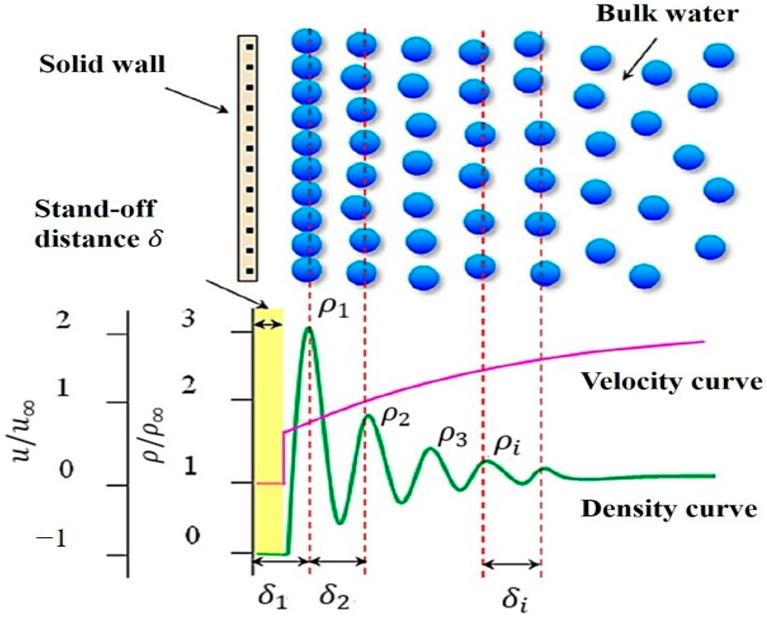
As seen in Figure 8, there are two regions with different transport properties, including a bulk region with a thickness of r b and a near-wall region with a thickness of r 0 r b . The properties of the bulk region are the same as the unconfined oil, while the properties of the near-wall region are strongly dependent on the relative strength of the oil intermolecular interaction and the oil–wall interaction. r 0 is the radius of the nanopore, while l s t is the slip length without considering the change in the viscosity with position. When the fluid viscosity near the wall is higher than that in the central region, the slip length is l h v ; while the slip length is l s t + l l v when the fluid viscosity near the wall is lower than the central region. In addition, the fluid flow in both regions conforms to the continuity assumption, the flow control equation for both regions can be expressed as follows: [68]
μ b r r r v b r = p z , r 0 , r b
μ n w r r r v n w r = p z , r r b , r 0
where μ b and μ n w are the dynamic viscosity of oil in the unconfined standard state and the near-wall oil, respectively; v b and v n w are the oil velocities of the bulk region in the axial direction of the pore and the near-wall oil in the axial direction of the pore.
By introducing boundary conditions, the integration yields that the equation for the flow of shale oil in the nanopores of the organic matrix of the shale can be expressed as
q = φ τ π 8 μ b r b 4 + μ b μ n w r 0 4 r b 4 + 4 r 0 3 l s t 𝛻 p L
where q is the total volumetric flux of oil transport in a circular nanopore; 𝛻 p / L is the externally applied pressure gradient with a pore length of L ; τ is the bending coefficient; and φ is the porosity.
According to Darcy’s equation, the liquid flow rates through the system can also be given by
q = K A O P , N P A μ b 𝛻 p L
That is, through comparing Equations (8) and (9), the apparent permeability of shale oil at the nanopore scale is obtained as
K A O P , N P = φ 8 τ r b 4 r 0 2 1 μ b μ n w + μ b μ n w r 0 2 + 4 r 0 l s t
Among them, the slip length of shale oil in organic and inorganic pores ( l s t ) and the fluid viscosity at the pore wall ( μ n w ) are the key parameters for calculating the apparent permeability of the two different pores, and this difference is caused by the different wetting characteristics of shale oil in the two pores, which can be obtained using empirical equations and multi-parameter fitting. The calculated results of the model were compared with the molecular dynamics simulation results, and the two were in better agreement, as shown in Figure 9. The results show that the oil has a relatively small slip length in inorganic pores with a parabolic velocity distribution, while the slip length in organic pores is so large that the velocity distribution changes from being parabolic to plunger-like. They provide a possible explanation, as when oil is transported on the surface of organic nanopores, the alkane molecules adsorbed on the pore surface can move freely, similar to the surface diffusion of adsorbed gaseous hydrocarbons.
Many researchers have used carbon nanotubes or slits constructed by graphene instead of organic matter pores and single-component alkanes, such as decane and n-octane, instead of shale oil to investigate the flow mechanism of shale oil in organic matter pores via experimental methods. However, this simulation is too simplified and tends to overestimate the flow ability of oil in kerogen. Zhao et al. [65] simulated shale oil with a single component n-dodecane by conducting two-core series tests in shale oil cores to obtain more realistic simulation results. They proposed the concept of threshold stress; when the effective stress on the organic matrix reaches this threshold stress, the oil will be squeezed into the surrounding inorganic pores. The experimental results show that the flow of shale oil was affected by the permeability of organic and inorganic matrices, the stiffness of the inorganic matrix, pressure drawdown, and the matrix size. In addition, Li [48] concluded that the flow pattern of shale oil in organic pores is like that in inorganic pores, but he did not consider the compressibility of the rock matrix in his calculations and argued that the change in porosity due to the shrinkage of the kerogen in organic matter is much greater than the effect of the change in the compression of the rock matrix. Moreover, he introduced a source term by considering the release of hydrocarbons from the shrinkage of kerogen.
From the above model, the velocity slip and viscosity inhomogeneity at the near-wall region play a key role in the flow of shale oil in organic pores, and the difference in the fluid flow properties between the near-wall surface and the bulk region is directly related to the thermal maturity or wettability of organic pores [69,70]. Wu et al. [71] concluded that the true slip length depends on the contact angle, and the apparent slip length, due to the viscosity inhomogeneity, is a function of wettability, as well as the dimension, and they modified the Hagen–Poiseuille equation to establish the confined water flow model and found that the water flow capacity was enhanced by 10 1 ~ 10 7 times by considering the effect of the wettability and dimension. The model was also applicable to shale oil flow in organic pores, explaining why small-sized organic pores have a stronger flow capacity than large-sized inorganic pores. Yassin et al. [72] found a positive correlation between the maturity and wettability of organic matter. Therefore, shale oil flow is more difficult in the pore space of kerogen with a high maturity of organic matter.

2.3.4. Coupling of Diffusion and Fluid Transport in the Organic Matrix

The diffusion transport coupling of shale oil is due to the occurrence of complex molecular interactions, manifested by boundary slip effects and viscosity/density inhomogeneous properties. Considering the complexity of the diffusion–transport coupling of dissolved oil in the kerogen, many scholars also calculate the apparent permeability by introducing an overall apparent permeability to calculate the flow properties of shale oil to obtain a percolation equation that facilitates engineering calculations. A few scholars describe transport and diffusion through independent equations; for example, Li et al. [46] considered the time dependence of the dissolved oil release in the kerogen and established the coupling of the radial diffusion of the dissolved oil in the kerogen with axial Darcy flow in the organic pore via numerical methods.
At present, many researchers have established numerical models of oil flow in kerogen to simulate the flow of multicomponent hydrocarbon mixtures in real kerogen via numerical simulations, considering the roughness of the kerogen surfaces and geometric properties, the multicomponent properties of shale oil, and the interactions between shale oil molecules and organic pore wall molecules.

3. Numerical Simulation Methods in Shale Oil Flow

Although shale oil flow in shale pores can be studied through physical laboratory experiments to measure key parameters, such as apparent permeability, experimental studies of shale oil flow in shale pores at the microscale and nanoscale inevitably require a lot of time and the use of sophisticated and expensive experimental instruments with demanding experimental conditions and requirements, especially regarding the accuracy of the measurements. However, by studying the shale oil flow mechanism and establishing a mathematical model of shale oil flow, the shale oil flow can be simulated and studied by means of computer numerical simulation. In recent years, many scholars have studied shale oil flow via numerical simulation, and many useful conclusions have been drawn. Numerical simulation studies are divided into two major categories regarding the current shale oil flow simulations: microscopic and macroscopic. The main simulation methods for shale oil microflow are MDS, LBM, and PNM. The main simulation methods for hydraulic fracture expansion in shale reservoirs are XFEM, DDM, and DEM. A dual-porosity model couples macroscopic and microscopic flows of shale oil to simulate the shale oil production process. Based on different theoretical foundations, different simulation methods have their own scope of application, advantages, and disadvantages.

3.1. Shale Oil Microflow Simulation

3.1.1. Molecular Dynamics Simulation

MDS uses Newton’s laws of motion to simulate the trajectories of atoms or molecules in a multibody system and calculates the structure and properties of the system by statistically averaging the ensemble of its different states. For equilibrium systems, statistical averages of physical quantities can be obtained by appropriate time averaging; for non-equilibrium systems, physical phenomena occurring within a molecular dynamics observation time can be simulated. For example, Wang et al. [20] analyzed the molecular structure and diffusion characteristics of n-octane within the slit (pore throat diameter: 1.7–11.2 nm) using equilibrium molecular dynamics (EMD) simulations; calculated the velocity profile, fluid viscosity distribution, and slip length of n-octane within the slit (pore throat diameter: 1.7–11.2 nm) using nonequilibrium molecular dynamics (NEMD) to calculate the velocity profile, fluid viscosity distribution, and slip length within the slit; and found that the flow of octane in the middle region of the quartz nanopore tends to be bulk-liquid-like, while the diffusion is much slower in the region near the wall, and there are obvious velocity and slip changes in the flow of alkane fluid in the inorganic pore driven by external forces-induced slippage and viscosity changes, as shown in Figure 10.
Due to the fact that MDS can obtain many microscopic details that are not available in experiments, explain difficult experimental phenomena, and reveal the occurrence mechanism, it has been widely applied in the study of shale oil and gas flow mechanisms in recent years. MDS has demonstrated excellent roles in revealing shale oil and gas adsorption mechanisms, solid–liquid interactions and liquid-liquid interactions, and revising or establishing new transport mechanics equations. For example, Falk et al. [21] demonstrated that due to strong molecular adsorption, the flow of an alkane fluid in kerogen cannot be described by the conventional Darcy’s law and proposed a microscopic description of permeability based on statistical mechanics. Liu et al. [22] investigated the inhomogeneous distribution of the density and fraction of shale oil in the organic matter of kerogen via MDS, as shown in Figure 11. It was found that the heavy fraction was concentrated in bulk phase regions, and the light fraction was concentrated at the boundary layer of the wall due to the reflection effect of the wall of kerogen. The velocity distribution of the bulk phase regions showed a plug flow when the external force increased, while there was a half-parabolic distribution at the boundary layer. The velocity distribution of the bulk phase regions showed a plug flow when the external force increased, while the boundary layer showed a half-parabolic distribution.
Zhang et al. [26] established two mathematical models, the apparent viscosity model and the liquid–liquid slip model, based on the oil–water two-phase flow phenomena demonstrated by molecular dynamics simulations, and validated the modified mathematical models by comparing them with the results of molecular dynamics simulations and the previous models that did not consider the liquid–liquid interface phenomena. In addition, we can not only establish more accurate mathematical models via MDS, but also use the flow parameters obtained from MDS as known conditions for other larger-scale simulation methods.
Although the results of MDS are accurate, researchers are currently facing the following problems when using MDS: the computation is very large, and the current scale that can be simulated is very small, generally in the tens of nanometers, so it is not possible to directly simulate fluid flow in complex porous media; the credibility of MDS results mainly depends on the accuracy of the interatomic interaction potential; for rock samples with complex compositions, it is also a challenging topic to build more accurate whole-molecule models of shale oil and molecular structures that are closer to that of kerogen.

3.1.2. Lattice Boltzmann Method

LBM is a mesoscopic approach between the microscopic (molecular) and macroscopic (continuum) scales, which can easily handle fluid flow in complex structures and is becoming an effective tool for simulating fluid flow in porous media. Through parallel computation and algorithm simplification, it is able to reduce computational resources to a large extent. M.P. Lautenschlaeger et al. [17] proposed a simple and effective LBM that is particularly suitable for non-homogeneous porous media with good numerical stability and has many application scenarios, including, of course, shale oil–water flow. LBM is a direct numerical simulation method, using MDS to obtain microscopic parameters such as the velocity/density distribution of shale oil in organic or inorganic nanopores, fitting velocity/density distribution through LBM single nanopore simulation to obtain lattice parameters such as slip length and solid–liquid interaction force, and finally extending single nanopore shale oil flow to complex porous media flow based on this fitted lattice parameter to further study the influence mechanism of complex parameters such as non-homogeneous wetting and pore geometry on apparent permeability [73,74,75]. For example, Zhang et al. [27] introduced the interaction between water molecules and solid walls into the LBM equation and proposed a mesoscopic LBM to capture the density distribution and velocity distribution of water flowing in nanopore channels, as shown in Figure 12.
Similarly, Zhao et al. [28] expressed the molecular interaction between water and solid walls in terms of real and apparent slip, and by fitting a large number of numerical simulation results of LBM, a nanopore water flow model with different cross-sectional shapes was established and expressed as the following empirical equation, which is easily applicable for widespread use in engineering.
Q = A 2 μ d a + b ( cos θ + 1 ) 2 A + c G + d G 2 + e ( cos θ + 1 ) 2 A G Δ p
Where the coefficients a e denote empirical constants [28]; Q is the flow rate; A is the cross-sectional surface area; Δ p represents the pressure drop; G is the shape factor; θ indicates the contact angle; and μ d is the effective viscosity, i.e., a constant in a water–nanopore system with a specific dimension.
At present, most scholars use LBM to study the flow law of water in nanoporous media, and the proposed model can also be used to study the flow of shale oil in nanoporous media. The key points to account for when using LBM to study shale oil and gas flow [76] are how to accurately consider the solid–liquid interaction and liquid–liquid interaction, how to consider the wall roughness, the development of new wall boundary treatment methods, and the introduction of new wall force models, etc.

3.1.3. Pore Network Model

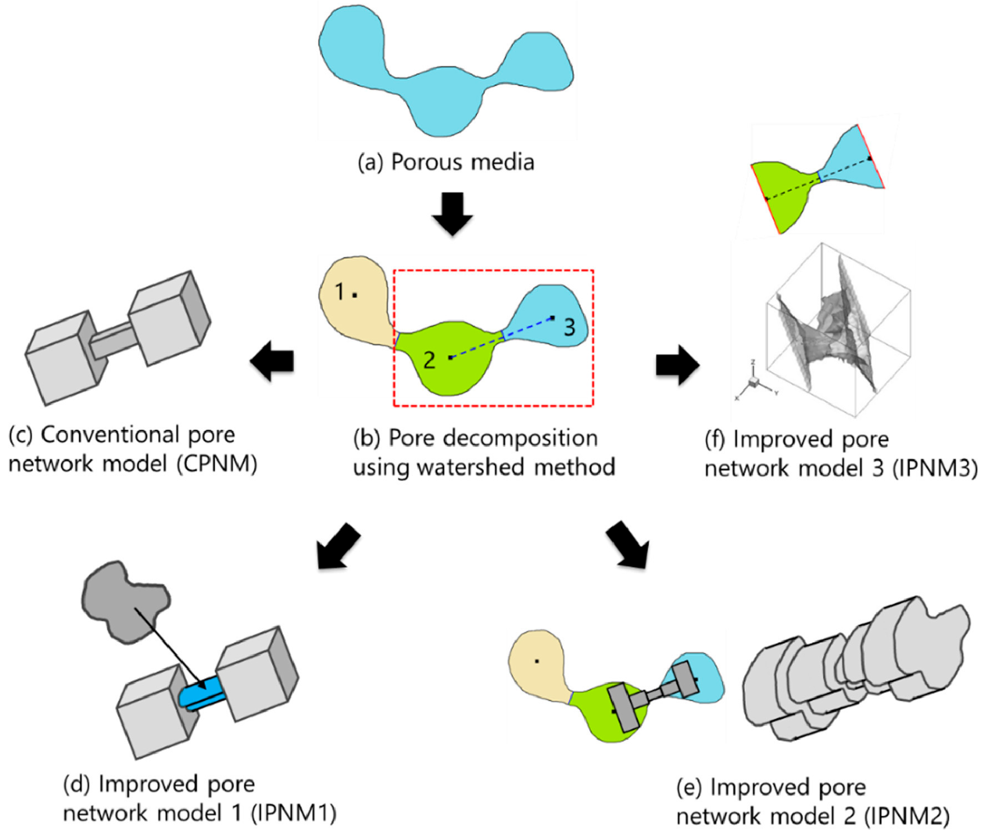
A PNM abstracts the rock as a network consisting of large spatial pores and narrow spatial pore throats, which are the smallest computational units in the simulation of the rock flow process [77,78]. The advantage of a pore network is that it can reflect the geometric topology and connectivity of the core in a more realistic way. The pore space is only used as a storage space during the calculation, and the flow and pressure in the pore throat can be calculated directly by applying existing mechanical laws without simulating the details of body flow; so, the calculation is very efficient compared to LBM and suitable for studying the shale oil flow mechanism at the microscale [79]. Based on the modified shale oil flow equation, Yang et al. [80] established a new PNM to investigate the effects of slip length and the adsorption effects on shale oil permeability and found that shale oil flow is mainly controlled by inorganic pores at low TOC, while the connectivity between organic pore throats is improved with increasing organic matter content. In recent years, traditional PNMs have used ball-and-stick models without considering the characteristics of the true pore structure, and a fast and accurate calculation method has been established by combining the PNM with direct simulation. Zhao et al. [81] found that the accuracy of the computational model is inversely proportional to the computational speed by comparing three sets of numerical simulations of single-phase fluids in porous media, as shown in Figure 13. They concluded that, in order to obtain an efficient and accurate model, it is a good choice to first simplify the real pore network to some extent and then compute it by LBM, and this method was called the improved pore network model (IPNM).
There is nothing special in the calculation method of PNM. PNM can be calculated by applying the existing laws of mechanics, and whether it is properly applied depends mainly on the construction of the pore network. In recent years, especially with the popularization and application of FIB/SEM technology, it has become a trend to build a more seamless pore network, so the construction of the pore network from core microscopic images has caused PNM to be more widely used [82]. Adding structural features, mineral components, and surface structural properties of rock samples into the pore network is a problem to be considered by PNM. In fact, PNM can be used as an effective tool to upscale MD (or LBM) results. PNM can reflect the basic characteristics and connectivity of rock structure but can also easily integrate MD (or LBM) results into it, and at the same time, PNM is computationally efficient compared with the other two methods, which facilitates a larger range of flow simulation calculations.

3.2. Shale Oil Microflow and Macroflow Coupling Model

In recent years, the development of hydraulic fracturing and horizontal well drilling technologies has made it possible to commercially exploit shale oil and gas resources endowed in low permeability rocks. As we know from the previous part of this article, shale oil flows in nanoscale pores in the shale matrix subject to many micromechanical behaviors that result in the flow of shale oil in nanopores that cannot be described by the conventional Darcy’s law. However, fractures formed by hydraulic fracturing reach the millimeter level, and compared to the flow of shale oil and gas in the shale matrix, it is believed that the flow of shale oil in artificial hydraulic fractures belongs to the macroscopic flow of shale oil and the microscopic effects can be neglected, so the flow can be described by Darcy’s law.
There are many studies on shale oil microflow and macroflow mechanisms, and researchers have developed their own theoretical models. Coupling shale oil microflow and macroflow is crucial for shale reservoir development. Quintard et al. [83] derived the following exact equivalent permeability equation from the large-scale averaging method for the two reservoirs with the layered arrangement shown in Figure 14.
K = f 1 K 1 + f 2 K 2 + f 1 f 2 K 1 K 2 1 0 0 0 K 2 K 1 1 , 0 f 1 K 2 + f 2 K 1 1 0
Where K 1 , K 2 is the permeability tensor of the two media; and f 1 , f 2 is the proportion of the two media, f 1 + f 2 = 1 .
If the permeability of the medium is a scalar, it is obtained from Equation (12)— K x x = K 1 K 2 / f 1 K 2 + f 2 K 1 , K x y = K y x = 0 , K y y = f 1 K 1 + f 2 K 2 —i.e., the equivalent permeability is a harmonic average in the x-direction and an arithmetic average in the y-direction. This approach to dealing with permeability inhomogeneities acts as a guide for the coupling microscopic and macroscopic flows in shale oil [84]. If one considers the flow of shale oil in matrix and hydraulic fractures as flow in two porous materials with different permeabilities, then averaging these two different permeabilities in a certain way (harmonic average, arithmetic average, geometric average, etc.), will yield a “rough permeability” that can be applied in engineering. However, the hydraulic fracture orientation is very complex in production practice, and it is difficult to use large-scale averaging under such conditions. Moreover, this method is not accurate in simulating multiphase flow [85].
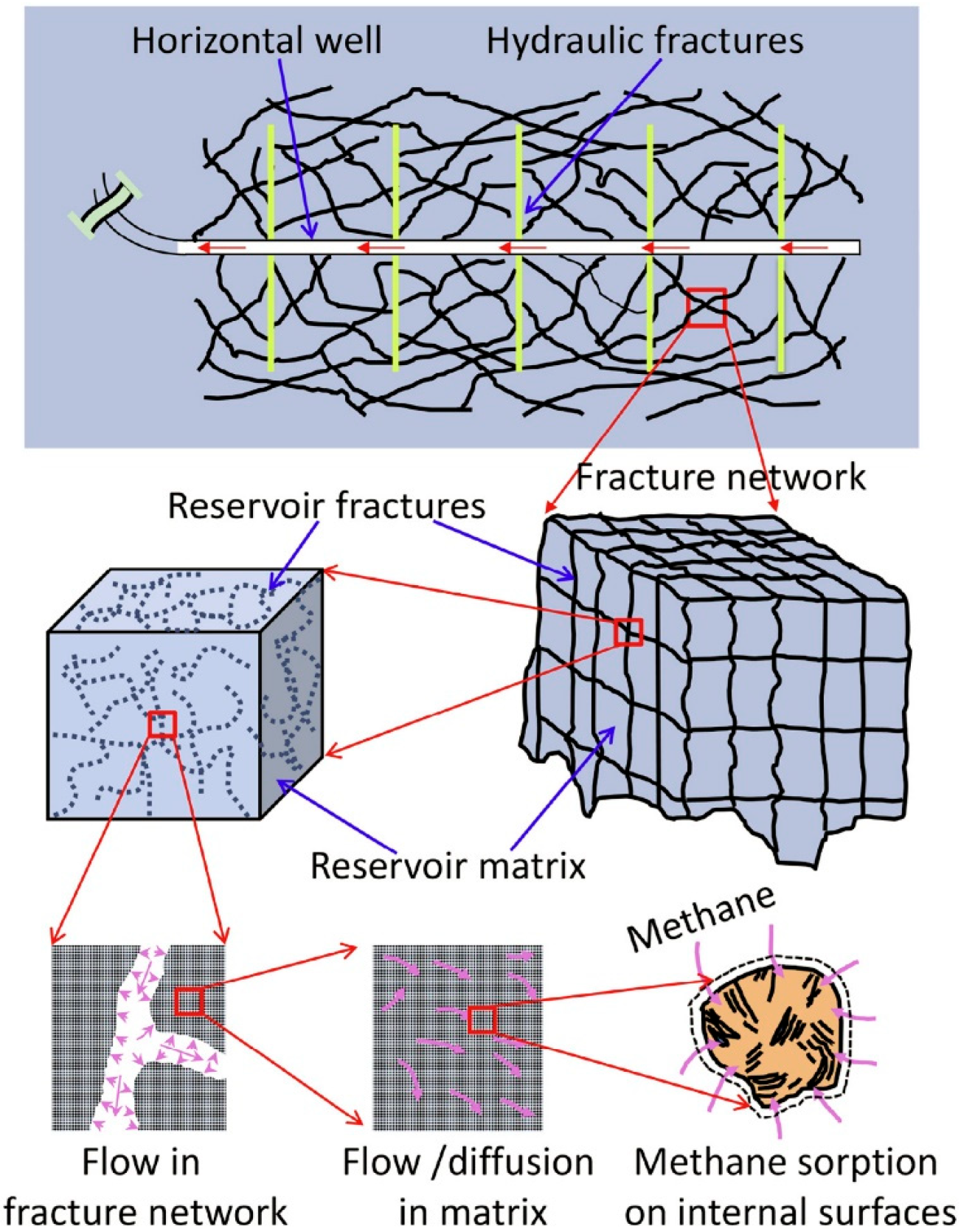
In recent years, many researchers have studied the coupling of shale oil microscopic and macroscopic flows more precisely, and have developed a dual-porosity model to study the multiscale flow of shale oil [86,87,88,89,90,91,92]. We know that hydraulic fractures are the main transport channel for oil and gas, and the pore structure of the shale matrix is the natural storage space for oil and gas. Shale reservoirs have a typical double-porous medium structure, and according to this feature of the reservoir, a coupling model of double-porous media, which considers the oil and gas flow in the matrix, oil and gas flow in the fractures, and reservoir deformation, can be established, as shown in Figure 15.
The microscopic flow mechanism of shale oil has been elucidated in the above section, which mainly includes adsorption, resolution and diffusion, etc., specifically in terms of density/velocity inhomogeneity, and the corresponding mathematical model can be established; the flow of shale oil in hydraulic fractures follows Darcy’s law; the oil reservoir also changes during the extraction process, following the rock equation of state; reservoir permeability changes and pressure changes, etc., can also be taken into account. The model then sets the same flow rate or pressure at the boundary of different media, thus coupling the above-mentioned multiscale flow in the reservoir development process, and the established mathematical model is solved numerically to realize the dynamic simulation of the reservoir development process. Su et al. [87] established a dual-porosity model to explain the quasi-steady cross-flow between fracture and matrix consisting of viscous flow and the steady adsorption and desorption process. Zhang et al. [88] used fractal theory to describe the stimulated reservoir volume (SRV) in order to characterize the complex fracture network structure after hydraulic fracturing, and coupled fractal relations with a dual-porosity model to establish a new semi-analytical model for simulating the effectively stimulated volume of fractured wells in tight reservoirs, which simulates the flow of shale oil in the fracture-modified reservoirs, as shown in Figure 16.
At present, the characterization of the fracture network is still relatively simple in most of the studies, and the complex fracture network structure is usually replaced by a few straight lines, which is obviously not accurate enough. Many previous studies on the formation of the fracture network of hydraulic fracturing have been conducted, and there are various numerical simulation methods (such as XFEM, DDM, and DEM, etc.), that can simulate the expansion of hydraulic fracturing under specific conditions. However, it is difficult to solve the coupled model under the complex fracture network, and solving the dual-porosity model while considering multiple micromechanical behaviors under the macroscopic complex fracture network is also a major difficulty in the research.

4. Conclusions and Perspectives

In this study, we briefly summarized the recent advances in the oil flow mechanism in shales and numerical simulation methods in shale oil flow. The shale oil flow in organic and inorganic pores of the shale matrix is considered to still follow the continuity assumption, but, in fact, the flow will be affected by microscopic effects. The interaction between fluid molecules and solid walls leads to the nonuniform distribution of the viscosity and density of shale oil. The flow near a certain thickness of the wall is affected by velocity slip and viscosity/density inhomogeneities, and the traditional Darcy’s equation and Hagen–Poiseuille equation cannot accurately represent the flow state of shale oil. Currently, some scholars are calculating the shale oil flow by considering the slip length, introducing effective viscosity, or conducting zoning studies on the fluid in nanopores before subsequently introducing a modified Darcy’s equation for the apparent permeability to facilitate the engineering calculations.
Since the shale oil flow in the nanopores of the shale matrix involves the study of the molecular scale, the MDS is widely used in shale oil flow with accurate simulation. It can consider the complex interactions between molecules near the solid–liquid contact surface during shale oil flow, and the microscopic parameters such as the velocity/density distribution obtained by MDS can be used as the basic parameters of the LBM and PNM. However, in the current study, when simulating fluid flow in organic and inorganic pores using MDS, only a range of tens of nanometers can be simulated, which is 1–2 orders of magnitude smaller than the real pores of shale, and we know that the slip length converges towards zero for increasing pore diameters; therefore, whether the microscopic parameters, such as the velocity/density distribution, currently obtained by MDS can reflect the real situation is also debatable. The LBM is easy to program, efficient in parallel, and can handle complex geometric boundary problems. It has been gradually applied to study the flow mechanism of microscopic porous media in recent years, while the PNM is computationally simple and efficient because it models the real pore network of rock samples. Applying shale oil microscopic transport parameters (slip length and near-wall fluid viscosity/density) and wall roughness, tortuosity, and inhomogeneous wettability to the LBM and PNM is an existing problem that requires further study.
Shale oil macroflow is the flow in millimeter-scale hydraulic fractures after hydraulic fracturing modification, which follows Darcy’s law, and a dual-porosity model is proposed in order to couple shale oil microflow and macroflow. This model theoretically allows us to fully consider the respective influencing factors in the microscopic and macroscopic models and couple the microscopic and macroscopic flow models by setting the same boundary conditions at the boundary and solving them numerically. However, in many cases, taking multiple influencing factors into consideration can make the coupled model complex, and it is difficult to solve the model of the fracture network structure under complex conditions.
In order to improve the shale oil recovery rate and alleviate the energy crisis, we should clarify the shale oil fugacity and percolation mechanism from the microscopic nanopore perspective, fully consider the coupling effects of various microscale effects, establish a more comprehensive shale oil percolation model, combine the advantages of the various existing microscale simulation methods, and develop numerical methods that ensure the accuracy of the calculation. From a macroscopic reservoir perspective, volumetric modifications and hydraulic fracture expansion mechanisms should be studied to improve shale reservoir permeability. In this way, the state of shale oil flow can be clarified at each step of production so that the production methods can be adjusted to extract the maximum amount of shale oil.

Author Contributions

Conceptualization, W.S.; Data curation, Z.L. (Zhiyu Li); Funding acquisition, W.S.; Investigation, Z.L. (Zhiyu Li), W.S. and Z.L. (Zhengdong Lei); Resources, Z.L. (Zhiyu Li), X.H. and D.A.M.; Validation, Z.L. (Zhiyu Li) and Z.L. (Zhengdong Lei); Writing—original draft preparation, Z.L. (Zhiyu Li); Writing—review and editing, W.S. All authors have read and agreed to the published version of the manuscript.

Funding

This work was supported by the National Natural Science Foundation of China (no. 12172362), the China National Petroleum Corporation (CNPC) Innovation Found (2021DQ02-0204), and the Youth Innovation Promotion Association of the Chinese Academy of Sciences.

Data Availability Statement

Not applicable.

Conflicts of Interest

The authors declare no conflict of interest.

References

  1. US Energy Information Administration (EIA). How Much Shale (Tight) Oil Is Produced in the United States? Available online: https://www.eia.gov/tools/faqs/faq.php?id=847&t=6 (accessed on 4 October 2022).
  2. Liu, X.H.; Xia, P.; Zhu, Q. Global oil market situation and future trend in 2020. Nat. Resour. Inf. 2021, 5, 3–10. [Google Scholar]
  3. Zhao, W.; Hu, S.; Hou, L.; Yang, T.; Li, X.; Guo, B.; Yang, Z. Types and resource potential of continental shale oil in China and its boundary with tight oil. Pet. Explor. Dev. 2020, 47, 1–11. [Google Scholar] [CrossRef]
  4. Cao, C.; Jia, P.; Cheng, L.; Jin, Q.; Qi, S. A review on application of data-driven models in hydrocarbon production forecast. J. Pet. Sci. Eng. 2022, 212, 110296. [Google Scholar] [CrossRef]
  5. Sang, Q.; Zhao, X.; Liu, Y.; Li, Z.; Dong, M. Effects of the laminated-structure and mixed wettability on the oil/water relative permeabilities and oil productions in shale oil formations. J. Pet. Sci. Eng. 2022, 208, 109457. [Google Scholar] [CrossRef]
  6. Xu, Y.; Lun, Z.; Pan, Z.; Wang, H.; Zhou, X.; Zhao, C.; Zhang, D. Occurrence space and state of shale oil: A review. J. Pet. Sci. Eng. 2022, 211, 110183. [Google Scholar] [CrossRef]
  7. Wu, T.; Pan, Z.; Liu, B.; Connell, L.D.; Sander, R.; Fu, X. Laboratory Characterization of Shale Oil Storage Behavior: A Comprehensive Review. Energy Fuels 2021, 35, 7305–7318. [Google Scholar] [CrossRef]
  8. Zhang, W.; Feng, Q.; Wang, S.; Xing, X. Oil diffusion in shale nanopores: Insight of molecular dynamics simulation. J. Mol. Liq. 2019, 290, 111183. [Google Scholar] [CrossRef]
  9. Jin, Z.; Wang, G.; Liu, G.; Gao, B.; Liu, Q.; Wang, H.; Lang, X.; Wang, R. Research progress and key scientific issues of continental shale oil in China. Acta Pet. Sin. 2021, 42, 821–835. [Google Scholar]
  10. Roy, S.; Raju, R.; Chuang, H.F.; Cruden, B.A.; Meyyappan, M. Modeling gas flow through microchannels and nanopores. J. Appl. Phys. 2003, 93, 4870–4879. [Google Scholar] [CrossRef]
  11. Feng, Q.; Xu, S.; Wang, S.; Li, Y.; Gao, F.; Xu, Y. Apparent permeability model for shale oil with multiple mechanisms. J. Pet. Sci. Eng. 2019, 175, 814–827. [Google Scholar] [CrossRef]
  12. Xiao, J.R.; Wei, J. Diffusion mechanism of hydrocarbons in zeolites—II. Analysis of experimental observations. Chem. Eng. Sci. 1992, 47, 1143–1159. [Google Scholar] [CrossRef]
  13. Wang, H.; Su, Y.; Wang, W.; Sheng, G.; Li, H.; Zafar, A. Enhanced water flow and apparent viscosity model considering wettability and shape effects. Fuel 2019, 253, 1351–1360. [Google Scholar] [CrossRef]
  14. Han, Y.; Horsfield, B.; Wirth, R.; Mahlstedt, N.; Bernard, S. Oil retention and porosity evolution in organic-rich shales. AAPG Bull. 2017, 101, 807–827. [Google Scholar] [CrossRef]
  15. Sang, Q.; Zhao, X.Y.; Liu, H.M.; Dong, M.Z. Analysis of imbibition of n-alkanes in kerogen slits by molecular dynamics simu-lation for characterization of shale oil rocks. Pet. Sci. 2022, 19, 1236–1249. [Google Scholar] [CrossRef]
  16. Wang, S.; Liang, Y.; Feng, Q.; Javadpour, F. Sticky layers affect oil transport through the nanopores of realistic shale kerogen. Fuel 2022, 310, 122480. [Google Scholar] [CrossRef]
  17. Lautenschlaeger, M.P.; Weinmiller, J.; Kellers, B.; Danner, T.; Latz, A. Homogenized lattice Boltzmann model for simulating multi-phase flows in heterogeneous porous media. Adv. Water Resour. 2022, 170, 104320. [Google Scholar] [CrossRef]
  18. Saif, T.; Lin, Q.Y.; Butcher, A.R.; Bijeljic, B.; Blunt, M.J. Multi-scale multi-dimensional microstructure imaging of oil shale py-rolysis using X-ray micro-tomography, automated ultra-high resolution SEM, MAPS Mineralogy and FIB-SEM. Appl. Energy 2017, 202, 628–647. [Google Scholar] [CrossRef]
  19. Zhan, H.; Li, X.; Hu, Z.; Duan, X.; Guo, W.; Li, Y. Influence of Particle Size on the Low-Temperature Nitrogen Adsorption of Deep Shale in Southern Sichuan, China. Minerals 2022, 12, 302. [Google Scholar] [CrossRef]
  20. Wang, S.; Javadpour, F.; Feng, Q. Molecular dynamics simulations of oil transport through inorganic nanopores in shale. Fuel 2016, 171, 74–86. [Google Scholar] [CrossRef]
  21. Falk, K.; Coasne, B.; Pellenq, R.; Ulm, F.-J.; Bocquet, L. Subcontinuum mass transport of condensed hydrocarbons in nanoporous media. Nat. Commun. 2015, 6, 6949. [Google Scholar] [CrossRef]
  22. Liu, J.; Yang, Y.; Sun, S.; Yao, J.; Kou, J. Flow behaviors of shale oil in kerogen slit by molecular dynamics simulation. Chem. Eng. J. 2022, 434, 134682. [Google Scholar] [CrossRef]
  23. Ho, T.A. Water and Methane in Shale Rocks: Flow Pattern Effects on Fluid Transport and Pore Structure. In Springer Theses; Springer Science and Business Media LLC: Berlin/Heidelberg, Germany, 2017; pp. 53–64. [Google Scholar]
  24. Xu, J.; Wang, R.; Zan, L. Shale oil occurrence and slit medium coupling based on a molecular dynamics simulation. J. Pet. Sci. Eng. 2023, 220, 111151. [Google Scholar] [CrossRef]
  25. Sui, H.; Zhang, F.; Wang, Z.; Wang, D.; Wang, Y. Molecular simulations of oil adsorption and transport behavior in inorganic shale. J. Mol. Liq. 2020, 305, 112745. [Google Scholar] [CrossRef]
  26. Zhang, W.; Feng, Q.; Wang, S.; Zhang, X.; Zhang, J.; Cao, X. Molecular Simulation Study and Analytical Model for Oil–Water Two-Phase Fluid Transport in Shale Inorganic Nanopores. Energies 2022, 15, 2521. [Google Scholar] [CrossRef]
  27. Zhang, T.; Javadpour, F.; Li, X.; Wu, K.; Li, J.; Yin, Y. Mesoscopic method to study water flow in nanochannels with different wettability. Phys. Rev. E 2020, 102, 013306. [Google Scholar] [CrossRef]
  28. Zhao, W.; Jia, C.; Zhang, T.; Jiang, L.; Li, X.; Jiang, Z.; Zhang, F. Effects of nanopore geometry on confined water flow: A view of lattice Boltzmann simulation. Chem. Eng. Sci. 2021, 230, 116183. [Google Scholar] [CrossRef]
  29. Liu, Y.; Zou, S.; He, Y.; Sun, S.; Ju, Y.; Meng, Q.; Cai, J. Influence of fractal surface roughness on multiphase flow behavior: Lattice Boltzmann simulation. Int. J. Multiph. Flow 2021, 134, 103497. [Google Scholar] [CrossRef]
  30. Zhang, T.; Li, X.; Yin, Y.; He, M.; Liu, Q.; Huang, L.; Shi, J. The transport behaviors of oil in nanopores and nanoporous media of shale. Fuel 2019, 242, 305–315. [Google Scholar] [CrossRef]
  31. Wang, Y.; Xia, Y.; Feng, Z.; Shao, H.; Qiu, J.; Ma, S.; Zhang, J.; Jiang, H.; Li, J.; Gao, B.; et al. Microscale Evaluation of Tight Oil Mobility: Insights from Pore Network Simulation. Energies 2021, 14, 4580. [Google Scholar] [CrossRef]
  32. Zhang, W.; Feng, Q.; Wang, S.; Zhang, J.; Jin, Z.; Xia, T.; Xing, X.; Lv, P. Pore network modeling of oil and water transport in nanoporous shale with mixed wettability. J. Pet. Sci. Eng. 2022, 209, 109884. [Google Scholar] [CrossRef]
  33. Zheng, H.; Yang, F.; Guo, Q.; Pan, S.; Jiang, S.; Wang, H. Multi-scale pore structure, pore network and pore connectivity of tight shale oil reservoir from Triassic Yanchang Formation, Ordos Basin. J. Pet. Sci. Eng. 2022, 212, 110283. [Google Scholar] [CrossRef]
  34. Shi, F.; Wang, D.B.; Li, H. An XFEM-based approach for 3D hydraulic fracturing simulation considering crack front segmen-tation. J. Pet. Sci. Eng. 2022, 214, 110518. [Google Scholar] [CrossRef]
  35. Rashid, H.; Olorode, O.; Chukwudozie, C. An iteratively coupled model for flow, deformation, and fracture propagation in fractured unconventional reservoirs. J. Pet. Sci. Eng. 2022, 214, 110468. [Google Scholar] [CrossRef]
  36. Belytschko, T.; Black, T. Elastic crack growth in finite elements with minimal remeshing. Int. J. Numer. Methods Eng. 1999, 45, 601–620. [Google Scholar] [CrossRef]
  37. Cong, Z.; Li, Y.; Pan, Y.; Liu, B.; Shi, Y.; Wei, J.; Li, W. Study on CO2 foam fracturing model and fracture propagation simulation. Energy 2022, 238, 121778. [Google Scholar] [CrossRef]
  38. Zhang, H.; Sheng, J.J. Complex fracture network simulation and optimization in naturally fractured shale reservoir based on modified neural network algorithm. J. Nat. Gas Sci. Eng. 2021, 95, 104232. [Google Scholar] [CrossRef]
  39. Pei, Y.; Yu, W.; Sepehrnoori, K.; Gong, Y.; Xie, H.; Wu, K. The Influence of Development Target Depletion on Stress Evolution and Infill Drilling of Upside Target in the Permian Basin. SPE Reserv. Eval. Eng. 2021, 24, 570–589. [Google Scholar] [CrossRef]
  40. Tang, J.; Wu, K.; Li, Y.; Hu, X.; Liu, Q.; Ehlig-Economides, C. Numerical investigation of the interactions between hydraulic fracture and bedding planes with non-orthogonal approach angle. Eng. Fract. Mech. 2018, 200, 1–16. [Google Scholar] [CrossRef]
  41. Crouch, S.L.; Starfield, A.M.; Rizzo, F.J. Boundary Element Methods in Solid Mechanics. J. Appl. Mech. 1983, 50, 704–705. [Google Scholar] [CrossRef]
  42. Crouch, S.L. Solution of plane elasticity problems by the displacement discontinuity method. I. Infinite body solution. Int. J. Numer. Methods Eng. 1976, 10, 301–343. [Google Scholar] [CrossRef]
  43. Jiao, K.; Han, D.; Li, J.; Bai, B.; Gong, L.; Yu, B. A novel LBM-DEM based pore-scale thermal-hydro-mechanical model for the fracture propagation process. Comput. Geotech. 2021, 139, 104418. [Google Scholar] [CrossRef]
  44. Varzaneh, A.A.S.; Ahmadi, M.; Goshtasbi, K. Simulation of hydraulic fracturing and Darcy fluid flow in a porous medium using a coupled Discrete Element Method with fluid flow. J. Pet. Sci. Eng. 2021, 204, 108706. [Google Scholar] [CrossRef]
  45. Cundall, P.A.; Strack, O.D.L. A discrete numerical model for granular assemblies. Géotechnique 1979, 29, 47–65. [Google Scholar] [CrossRef]
  46. Li, S.; Sang, Q.; Dong, M.; Luo, P. Determination of inorganic and organic permeabilities of shale. Int. J. Coal Geol. 2019, 215, 103296. [Google Scholar] [CrossRef]
  47. Liu, F.; Kang, Y.; Hu, Y.; Xu, J.; Chen, H.; Pan, H.; Feng, G. New Model of Oil Migration in Shale Nanopores Considering Microscopic Deformation Induced by Stress and Pore Pressure. Energy Fuels 2022, 36, 14230–14242. [Google Scholar] [CrossRef]
  48. Li, S. Study of Oil Flow Mechanisms in Shale Reservoirs. Ph.D. Thesis, University of Calgary, Calgary, AB, Canada, 2020. Unpublished Doctoral Thesis. [Google Scholar]
  49. Xu, J.; Wang, W.; Ma, B.; Su, Y.; Wang, H.; Zhan, S. Stochastic-based liquid apparent permeability model of shale oil reservoir considering geological control. J. Pet. Explor. Prod. Technol. 2021, 11, 3759–3773. [Google Scholar] [CrossRef]
  50. Li, S.; Li, S.; Guo, R.; Zhou, X.; Wang, Y.; Chen, J.; Zhang, J.; Hao, L.; Ma, X.; Qiu, J. Occurrence State of Soluble Organic Matter in Shale Oil Reservoirs from the Upper Triassic Yanchang Formation in the Ordos Basin, China: Insights from Multipolarity Sequential Extraction. Nat. Resour. Res. 2021, 30, 4379–4402. [Google Scholar] [CrossRef]
  51. Liang, S.; Wang, J.-M.; Liu, Y.-K.; Liu, B.; Sun, S.; Shen, A.-Q.; Tao, F.-Y. Oil Occurrence States in Shale Mixed Inorganic Matter Nanopores. Front. Earth Sci. 2022, 9, 1456. [Google Scholar] [CrossRef]
  52. Zhang, K.; Jiang, S.; Zhao, R.; Wang, P.; Jia, C.; Song, Y. Connectivity of organic matter pores in the Lower Silurian Longmaxi Formation shale, Sichuan Basin, Southern China: Analyses from helium ion microscope and focused ion beam scanning electron microscope. Geol. J. 2022, 57, 1912–1924. [Google Scholar] [CrossRef]
  53. Chen, Y.; Zhu, Z.; Zhang, L. Control actions of sedimentary environments and sedimentation rates on lacustrine oil shale distribution, an example of the oil shale in the Upper Triassic Yanchang Formation, southeastern Ordos Basin (NW China). Mar. Pet. Geol. 2019, 102, 508–520. [Google Scholar] [CrossRef]
  54. Feng, Y.; Xiao, X.; Wang, E.; Sun, J.; Gao, P. Oil Retention in Shales: A Review of the Mechanism, Controls and Assessment. Front. Earth Sci. 2021, 9, 720839. [Google Scholar] [CrossRef]
  55. Zhang, A.D.; Wang, J.P.; Wang, Y.C.; Hong, S.X.; Tan, W.L. Reservoir space types and oil occurrence of Gulong shale in Songliao Basin. Pet. Geol. Oilfield Dev. Daqing 2021, 40, 68–77. [Google Scholar]
  56. Hu, T.; Pang, X.; Jiang, F.; Wang, Q.; Liu, X.; Wang, Z.; Jiang, S.; Wu, G.; Li, C.; Xu, T.; et al. Movable oil content evaluation of lacustrine organic-rich shales: Methods and a novel quantitative evaluation model. Earth-Sci. Rev. 2021, 214, 103545. [Google Scholar] [CrossRef]
  57. Huang, L.; Khoshnood, A.; Firoozabadi, A. Swelling of Kimmeridge kerogen by normal-alkanes, naphthenes and aromatics. Fuel 2020, 267, 117155. [Google Scholar] [CrossRef]
  58. Zhu, R.K.; Zhang, J.Y.; Li, M.Y.; Cai, Y.; Wu, S.T.; Liu, C.; Zhang, S.R.; Kang, Y. Advances and key issues in the basic research of non-marine shale oil enrichment. Acta Geol. Sin. 2023, 1–23. [Google Scholar]
  59. Ruppert, L.F.; Sakurovs, R.; Blach, T.P.; He, L.; Melnichenko, Y.B.; Mildner, D.F.R.; Alcantar-Lopez, L. A USANS/SANS Study of the Accessibility of Pores in the Barnett Shale to Methane and Water. Energy Fuels 2013, 27, 772–779. [Google Scholar] [CrossRef]
  60. Zou, C.N.; Yang, Z.; Pan, S.Q.; Chen, Y.Y.; Lin, S.H.; Huang, J.L.; Wu, S.T.; Dong, D.Z.; Wang, S.F.; Liang, F.; et al. Shale Gas Formation and Occurrence in China: An Overview of the Current Status and Future Potential. Acta Geol. Sin. 2016, 90, 1249–1283. [Google Scholar]
  61. Jagadisan, A.; Heidari, Z. Experimental Quantification of the Effect of Thermal Maturity of Kerogen on Its Wettability. SPE Reserv. Eval. Eng. 2019, 22, 1323–1333. [Google Scholar] [CrossRef]
  62. Sang, Q.; Zhang, S.; Li, Y.; Dong, M.; Bryant, S. Determination of organic and inorganic hydrocarbon saturations and effective porosities in shale using vacuum-imbibition method. Int. J. Coal Geol. 2018, 200, 123–134. [Google Scholar] [CrossRef]
  63. Li, R.; Chen, Z.; Wu, K.; Hao, X.; Xu, J. An analytical model for water-oil two-phase flow in inorganic nanopores in shale oil reservoirs. Pet. Sci. 2021, 18, 1776–1787. [Google Scholar] [CrossRef]
  64. Huang, J.; Jin, T.; Chai, Z.; Barrufet, M.; Killough, J. Compositional simulation of three-phase flow in mixed-wet shale oil reservoir. Fuel 2020, 260, 116361. [Google Scholar] [CrossRef]
  65. Zhao, X.; Sang, Q.; Li, Y.; Shi, L.; Liu, H.; Dong, M. Mobilization of oil in organic matter and its contribution to oil production during primary production in shale. Fuel 2021, 287, 119449. [Google Scholar] [CrossRef]
  66. Chen, T.; Feng, X.-T.; Pan, Z. Experimental study of swelling of organic rich shale in methane. Int. J. Coal Geol. 2015, 150–151, 64–73. [Google Scholar] [CrossRef]
  67. Su, Y.; Wang, H.; Zhan, S.; Wang, W.; Xu, J. Research progress on characterization and simulation of shale oil flow in microscale. J. Shenzhen Univ. Sci. Eng. 2021, 38, 579–589. [Google Scholar] [CrossRef]
  68. Myers, T.G. Why are slip lengths so large in carbon nanotubes? Microfluid. Nanofluid. 2011, 10, 1141–1145. [Google Scholar] [CrossRef]
  69. Gao, Z.Y.; Fan, Y.P.; Hu, Q.H.; Jiang, Z.X.; Cheng, Y.; Xuan, Q.X. A review of shale wettability characterization using spon-taneous imbibition experiments. Mar. Pet. Geol. 2019, 109, 330–338. [Google Scholar] [CrossRef]
  70. Li, X.F.; Feng, D.; Zhang, T.; Sun, Z.; He, M.X.; Liu, Q.; Liu, W.Y.; Zhao, W.; Li, J. The role and its application of capillary force in the development of unconventional oil and gas reservoirs and its application. Acta Pet. Sin. 2020, 41, 1719–1733. [Google Scholar]
  71. Wu, K.; Chen, Z.; Li, J.; Li, X.; Xu, J.; Dong, X. Wettability effect on nanoconfined water flow. Proc. Natl. Acad. Sci. USA 2017, 114, 3358–3363. [Google Scholar] [CrossRef] [PubMed]
  72. Yassin, M.R.; Begum, M.; Dehghanpour, H. Organic shale wettability and its relationship to other petrophysical properties: A Duvernay case study. Int. J. Coal Geol. 2017, 169, 74–91. [Google Scholar] [CrossRef]
  73. Li, Z.-Z.; Min, T.; Kang, Q.; He, Y.-L.; Tao, W.-Q. Investigation of methane adsorption and its effect on gas transport in shale matrix through microscale and mesoscale simulations. Int. J. Heat Mass Transf. 2016, 98, 675–686. [Google Scholar] [CrossRef]
  74. Takbiri-Borujeni, A.; Fathi, E.; Kazemi, M.; Belyadi, F. An integrated multiscale model for gas storage and transport in shale reservoirs. Fuel 2019, 237, 1228–1243. [Google Scholar] [CrossRef]
  75. Wang, H.; Wang, W.D.; Su, Y.L.; Jin, Z.H. Lattice Boltzmann Model for Oil/Water Two- Phase Flow in Nanoporous Media Considering Heterogeneous Viscosity, Liquid/Solid, and Liquid/Liquid Slip. SPE J. 2022, 27, 3508–3524. [Google Scholar] [CrossRef]
  76. Zachariah, G.T.; Panda, D.; Surasani, V.K. Lattice Boltzmann simulations for invasion patterns during drying of capillary porous media. Chem. Eng. Sci. 2019, 196, 310–323. [Google Scholar] [CrossRef]
  77. Cui, R.; Feng, Q.; Chen, H.; Zhang, W.; Wang, S. Multiscale random pore network modeling of oil-water two-phase slip flow in shale matrix. J. Pet. Sci. Eng. 2019, 175, 46–59. [Google Scholar] [CrossRef]
  78. Wang, X.; Zhang, Z.; Gong, R.; Wang, S. Pore Network Modeling of Oil–Water Flow in Jimsar Shale Oil Reservoir. Front. Earth Sci. 2021, 9, 738545. [Google Scholar] [CrossRef]
  79. Lin, M.; Jiang, W.B.; Li, Y.; Yi, Z.X.; Zhang, Z.B. Several Questions in the Micro-Scale Flow of Shale Oil/Gas. Bull. Mineral. Petrol. Geochem. 2015, 34, 18–28. [Google Scholar]
  80. Yang, Y.; Wang, K.; Zhang, L.; Sun, H.; Zhang, K.; Ma, J. Pore-scale simulation of shale oil flow based on pore network model. Fuel 2019, 251, 683–692. [Google Scholar] [CrossRef]
  81. Zhao, J.; Qin, F.; Derome, D.; Kang, Q.; Carmeliet, J. Improved pore network models to simulate single-phase flow in porous media by coupling with lattice Boltzmann method. Adv. Water Resour. 2020, 145, 103738. [Google Scholar] [CrossRef]
  82. Song, W.H.; Liu, L.; Sun, H.; Zhang, K.; Yang, Y.F.; Yao, J. Pore structure characterization and flow ability of shale oil reservoir based on digital cores. Pet. Reserv. Eval. Dev. 2021, 11, 497–505. [Google Scholar]
  83. Quintard, M.; Whitaker, S. Ecoulement monophasique en milieu poreux: Effet des hétérogénéités locales. J. Meca Theor. Appl. 1987, 6, 691–726. [Google Scholar]
  84. Mabiala, B.; Nsongo, T.; Tomodiatounga, D.N.; Tathy, C.; Nganga, D. Two-Dimensional Modeling of the NAPL Dissolution in Porous Media: Heterogeneities Effects on the Large Scale Permeabilities and Mass Exchange Coefficient. Comput. Water Energy Environ. Eng. 2017, 6, 56–78. [Google Scholar] [CrossRef]
  85. Wei, P.Y.; Shi, A.F.; Wang, X.H.; Zhou, F.Q. A Discrete Fracture-Dual Porosity Coupling Model for Shale Gas Reservoirs. Chin. Q. Mech. 2015, 36, 179–188. [Google Scholar]
  86. Xue, Y.; Teng, T.; Dang, F.; Ma, Z.; Wang, S.; Xue, H. Productivity analysis of fractured wells in reservoir of hydrogen and carbon based on dual-porosity medium model. Int. J. Hydrog. Energy 2020, 45, 20240–20249. [Google Scholar] [CrossRef]
  87. Su, Y.; Zhang, Q.; Wang, W.; Sheng, G. Performance analysis of a composite dual-porosity model in multi-scale fractured shale reservoir. J. Nat. Gas Sci. Eng. 2015, 26, 1107–1118. [Google Scholar] [CrossRef]
  88. Zhang, Q.; Su, Y.; Wang, W.; Sheng, G. A new semi-analytical model for simulating the effectively stimulated volume of fractured wells in tight reservoirs. J. Nat. Gas Sci. Eng. 2015, 27, 1834–1845. [Google Scholar] [CrossRef]
  89. Hu, Y.; Liu, G.; Luo, N.; Gao, F.; Yue, F.; Gao, T. Multi-field coupling deformation of rock and multi-scale flow of gas in shale gas extraction. Energy 2022, 238, 121666. [Google Scholar] [CrossRef]
  90. Micheal, M.; Xu, W.; Xu, H.; Zhang, J.; Jin, H.; Yu, H.; Wu, H. Multi-scale modelling of gas transport and production evaluation in shale reservoir considering crisscrossing fractures. J. Nat. Gas Sci. Eng. 2021, 95, 104156. [Google Scholar] [CrossRef]
  91. Zhang, Q.; Su, Y.L.; Wang, W.D.; Lu, M.J.; Ren, L. Performance analysis of fractured wells with elliptical SRV in shale reser-voirs. J. Nat. Gas Sci. Eng. 2017, 45, 380–390. [Google Scholar] [CrossRef]
  92. Rasoulzadeh, M.; Kuchuk, F.J. Pressure Transient Behavior of High-Fracture-Density Reservoirs (Dual-Porosity Models). Transp. Porous Media 2019, 129, 901–940. [Google Scholar] [CrossRef]
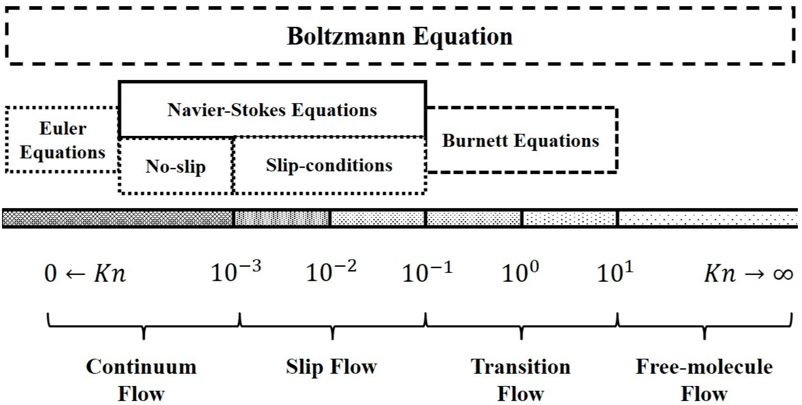
Figure 1. Sketch of the microscale gas flow regime [10].
Energies 16 03516 g001
Figure 2. SEM image of a shale sample from Dongying Sag showing the organic nanopores [16].
Energies 16 03516 g002
Figure 3. Schematic of oil flowing in inorganic and organic media [48].
Energies 16 03516 g003
Figure 4. Schematic of different fluids imbibition process and storage space in shale: (a) water only imbibe into inorganic pores; (b) oil imbibe into both organic and inorganic pores [62].
Energies 16 03516 g004
Figure 5. Distribution of the water and oil phases in a single nanopore (oxygen in water and carbon in oil are green spheres and black spheres, respectively) [63].
Energies 16 03516 g005
Figure 6. Schematic of the oil diffusion process with different totals of organic carbon (TOC) and porosity: (a) diffusion in kerogen with a constant porosity and different TOC; (b) diffusion in kerogen with a constant TOC and different porosities [62].
Energies 16 03516 g006
Figure 7. Schematic illustration of kerogen shrinkage under reduced pressure [48].
Energies 16 03516 g007
Figure 8. Physical conceptual model of no-slip Poiseuille flow and slip flow through a nanopore [30].
Energies 16 03516 g008
Figure 9. The comparisons between the proposed model and the MDS data with different pore sizes. (The upper figure represents organic nanopores; the lower one represents inorganic nanopores. The colored dots represent the results of the MDS; the solid, black lines are the results of the model calculations; and the dashed, grey lines represent the results without considering the viscosity inhomogeneity [30]).
Energies 16 03516 g009
Figure 10. Molecular model and velocity profiles of octane transports through quartz nanopores [20].
Energies 16 03516 g010
Figure 11. Number density profiles of kerogen and shale oil mixtures in the slit region; the red, dashed lines represent the boundaries of the bulk phase region [22].
Energies 16 03516 g011
Figure 12. Typical representation of water molecules near the wall surface in a nanochannel (>1.60 nm) [27].
Energies 16 03516 g012
Figure 13. Different pore network extraction methods based on the watershed method [81].
Energies 16 03516 g013
Figure 14. Schematic diagram of the layered reservoir [83].
Energies 16 03516 g014
Figure 15. Transport mechanism in a fractured organic reservoir of hydrogen and carbon [86].
Energies 16 03516 g015
Figure 16. Schematic of a vertically fractured well with a SRV in a tight reservoir [88].
Energies 16 03516 g016
Disclaimer/Publisher’s Note: The statements, opinions and data contained in all publications are solely those of the individual author(s) and contributor(s) and not of MDPI and/or the editor(s). MDPI and/or the editor(s) disclaim responsibility for any injury to people or property resulting from any ideas, methods, instructions or products referred to in the content.