Article

Integration of PV Sources in Prosumer Installations Eliminating Their Negative Impact on the Supplying Grid and Optimizing the Microgrid Operation

Institute of Electrical Power Engineering, Lodz University of Technology, 20 Stefanowskiego Street, 90-537 Lodz, Poland
*
Author to whom correspondence should be addressed.
Energies 2023, 16(8), 3479; https://doi.org/10.3390/en16083479
Submission received: 14 March 2023 / Revised: 13 April 2023 / Accepted: 13 April 2023 / Published: 16 April 2023

Abstract

:
This paper concerns the mitigation of voltage disturbances deteriorating power quality and disrupting the operation of LV distribution grids due to the high penetration of PV energy sources in prosumer installations. A novel control strategy for 3-phase 4-wire PV inverters is proposed, which ensures the transmission of PV active power and simultaneous compensation of load unbalance and reactive power, making the prosumer installation balanced and purely active. It results in the balance of phase voltages and the mitigation of their variability. Unlike other methods used for voltage regulation in LV grids, the proposed solution contributes to the reduction in losses, is simple, and does not require additional costs. In the paper, a control algorithm for the PV inverter is described. Its effectiveness was tested by simulation using a model of the real LV distribution grid developed in the PSCAD/EMTDC program. The results of the simulations are presented and evaluated.

1. Introduction

A continuous increase in the number of photovoltaic systems (PV) installed in end-user installations results in worsening of the operating conditions of the low-voltage (LV) distribution grids [1,2,3,4,5,6]. The most typical problems include an excessive voltage rise in the network nodes, which may appear if an extensive power is injected into the network, and the voltage unbalance caused by the load unbalance and the fact that PV sources are often the single-phase ones [7]. It is obvious that these phenomena negatively affect power quality (PQ), result in additional power and energy losses, and can cause disruptions in the operation of prosumer installations and the supplying network [8,9,10,11,12]. A major problem for prosumers is switching-off the PV inverters due to the effect of unacceptable voltage rise [7,13].
Maintenance of proper network operation and keeping the PQ indicators in the required range is the responsibility of the network operator (DSO). In networks with a high penetration of renewable energy sources and disturbing loads distributed in prosumer installations, it is difficult for the DSO to cope with overvoltage and unbalance phenomena without any control measures.
In existing distribution networks, the options of voltage regulation are limited. Direct voltage regulation involves a gradual change in the voltage transformation ratio of distribution transformers using transformer tap changers. As most of the distribution transformers currently in use are equipped with off-load tap-changers, an on-line voltage control is not possible. Replacing the traditional units with on-load tap changers allows an on-line voltage control but over longer time scales, e.g., 15 min. More frequent tap changing would lead to a significant reduction in their lifetime.
Indirect voltage regulation methods that involve changing the reactive power flow in the network in real-time are commonly applied in LV distribution grids. On a local scale, this method can be applied by using PV inverters located in the prosumer installations. The inverters can operate according to Q-P or Q-U strategies. In the first case, the reactive power is a function of its active power, whereas in the Q-U strategy it depends on the voltage measured at the point of common coupling (PCC). The increase in reactive power drawn from the network results in mitigation of the voltage rise at the PCC [14,15]. However, it should be emphasized that many PV inverters operate with cosφ = 1, so the range of change of reactive power is limited by the total current carrying capacity and may be relatively small in practice. It is worth mentioning that voltage regulation by reactive power may be ineffective in LV distribution networks due to the relatively low X/R ratio of the network impedance, thus reducing active power inserted to the grid may be necessary.
Another solution assumes the use of energy storage systems (ESSs) located in prosumer installations for energy management [16,17,18]. Both reactive and active power can be used for regulation purposes; however, it should be noted that the function of PQ improvement is a kind of ancillary service for the ESS and may interfere with its main task, which is active power management. Obviously, the DSO may use a dedicated ESS located in the grid for voltage regulation, but this solution is costly and does not ensure the desired effect in the whole grid.
Examples of decentralized voltage control by means of reactive and active power of PV inverters or ESSs can be found in numerous examples of the literature. A droop-based reactive power control and an active power curtailment algorithm are introduced in [19] for a PV inverter to avoid an unacceptable voltage rise. The algorithm uses only local measurements. The PV inverter at the critical bus changes its reactive power with a specific pattern, and as a result the voltages of all buses change with the same pattern. The active power curtailment is used as a last remedy to prevent unacceptable voltage rise and is shared equally between all inverters. In [20], the authors propose the volt-var-watt control strategy that can be used to improve the fairness of active power curtailment among inverters. In the presented strategy the inverters require one common reference setting that is calculated by the farthest PVs in each phase and shared among inverters. To apply the proposed control strategy, there is no need to provide communication between PV inverters.
The advantage of local control is in the higher autonomy of prosumers installations and the fact there are no requirements regarding the communication links. However, as the operating conditions of the grid can change rapidly, it is difficult to cope with the voltage problem in all network nodes if many controllable devices are involved in regulation and act autonomously. Thus, some coordination among local controllers of participating devices is necessary. This requirement leads to the development of centralized control systems, in which adjustment settings are determined by a central controller and sent to the controlled devices. In the centralized control systems, individual PV and ESS inverters are efficiently managed based on the data from the meters located along the network.
A centralized control strategy is presented in [21], where several functionalities, i.e., voltage regulation, the management of active power, and minimizing the energy costs, have been implemented for all resources in the LV grid, such as PVs, EVs, and UPSs. These functionalities are implemented by means of active and reactive power generation/consumption in order of priority. The provision of regulation service interferes with other functionalities.
The possibility of mitigating voltage disturbances in the LV networks with a large number of PV sources in prosumer installations is discussed in [22]. The authors developed the centralized, coordinated system that allows one to alleviate voltage changes in each phase individually and power flow congestions in the network by regulating the flow of reactive and active powers using PV inverters and ESSs in prosumer installations. The central controller takes control over the prosumer’s ESS only if there is a violation in the grid. In normal operating conditions, the local controller manages the ESS inverter operation with the priority being the prosumer’s benefit, i.e., reducing the cost of energy purchased from the grid.
The centralized coordinated systems may be effective tools for the DSOs, allowing them to control the voltage and manage the grid operation. However, it should be noted that they require a reliable and efficient communication infrastructure, which is not common in LV networks. It makes the system complicated and costly. It is worth adding that indirect voltage regulation by changing power flow in the network may increase power and energy losses.
In an overview of methods and means for mitigating the voltage disturbances, the possibility of using static compensators should also be mentioned. Their operation consists in compensating for disturbances appearing in current or voltage waveform, such as harmonics or unbalance. Compensators, such as active power filters (APFs) and distribution STATCOM systems (DSTATCOMs) [23,24,25], are well known, effective solutions dedicated to the compensation of particularly disturbing loads. They can stabilize the voltage at the PCC. However, they are costly and, mainly for this reason, are rarely applied in LV grids.
The literature review shows that to handle the voltage regulation problem in the grids with distributed energy sources, the DSO has to apply some dedicated control equipment or use the capability of devices (PV or ESS inverters) available in the prosumer installations. In both cases a coordination and communication system is necessary to ensure the required effect; however, this also makes the control system complex and costly. To the authors knowledge, there is no solution which would effectively mitigate excessive voltage values and unbalances throughout the grid without increasing network losses, and at the same time would be relatively simple and cheap to apply. This gap is addressed in this paper.
This paper presents a novel control strategy developed for the 3-phase 4-wire PV inverters, which combines the function of an interface for PV panels and a PQ compensator for the prosumer installation. The control strategy ensures the balancing of voltages at the PCC, mitigating excessive voltage rides that occurred under the conditions of high-power generation from PV panels, and maintaining the voltage values in the required range. The load reactive power is compensated, which results in the pure active character of the currents introduced to the grid. From the point of view of the DSO, the proposed control strategy makes the prosumer installation ideal, i.e., three phase, balanced, and of pure active load character.
The strategy enables the effective use of PV inverters with the benefit for prosumers and for the DSOs without the need for additional equipment. The proposed solution could be used at the stage of integration of PV sources with the supplying grid.
The paper is arranged as follows: in Section 2, the proposed control strategy, applied to PV inverters in prosumer installations, is described; then, in Section 3 the results of the simulations and their analysis are presented, and in Section 4 a summary of the effects of the proposed method and comparison with other approaches are presented. The last section includes conclusions.

2. Proposed Control Strategy of PV Inverters

2.1. Assumptions

The subject of consideration is an end-user installation coupled with the LV distribution network, as shown in Figure 1. In general, the installation includes unbalanced linear loads and PV panels integrated into the network by means of a 3-phase inverter whose basic task is transmitting energy generated by PV modules. Such an installation has a negative impact on the power grid’s power quality, due to excessive voltage values at the PCC that can appear with high PV generation, as well as unbalanced voltages that result from unbalanced currents flowing in the grid, as discussed in Section 1.
It is assumed that the negative impact of prosumer installations on the grid should be eliminated at the place of their origin, using the capabilities of the devices installed there. This way is relatively inexpensive and simple and does not require any communication infrastructure. The idea of the proposed solution is to make the installation as ideal as possible using a PV inverter. From the DSO’s point of view, ‘ideal’ means that the installation connected to the grid is balanced, sinusoidal, and purely active in the sense of power drawn from the grid. With all prosumer installations meeting these assumptions, the grid would operate with required power quality and with minimal power and energy losses. Therefore, an objective of the proposed control is to develop a control algorithm for the 3-phase 4-wire PV inverter that extends its functionality with the compensation of load unbalance and reactive power.

2.2. Inverter Topology

The range of regulation services for which the PV inverter can be applied for depends on its topology. Typically, in three phase networks and installations, the 3-phase 3-wire AC/DC converters are used. Such inverters may offer the control of active and reactive power and additional functionalities for PQ improvement. For instance, in [24] and [26] the authors proposed the method of controlling a three-phase, three-wire PV inverter, which, apart from supplying active and reactive power to the grid, can be used to reduce harmonic currents generated by non-linear loads.
Most of the control algorithms applied in practice for load compensation in the 3-phase systems use the theory of instantaneous powers and abc/αβ or abc/120 transformation [27,28]. In 3-wire systems, only positive and negative components of the unbalanced currents can be considered. The omission of zero sequence current in the LV grids, where single-phase loads and energy sources predominate, causes the compensation using the 3-wire topology of the inverters to not be fully effective. It requires the use of a 3-phase and 4-wire system with independently controlled instantaneous values of currents in each phase.
Examples of the 3-phase 4-wire PV converters with additional functionality related to PQ improvement can be found in the literature. In [29], the large-scale PV multilevel inverters connected to an injection transformer in PCC of LV grid were used for ancillary services, i.e., reduction in load unbalance and current harmonics in the feeder. The applied controller is developed on the αβo coordinate system. The authors note that for the capacity to fully compensate the load imbalance with the PV generator, the inverter should be oversized, and that the cost of the system might affect the compensation capability.

2.3. Inverter Control Algorithm

As mentioned above, the proposed control is based on load balancing using the PV inverter. Assuming that the load currents iload within the prosumer installation are unbalanced, the aim is to compensate the current components responsible for this disturbance to get currents drawn from the network i as balanced and purely active. Thus, the vector of phase currents flowing to the prosumer installation should have the form
i = I e j ω o t
where
i = [i L1 i L2 i L3]T—installation currents vector,
I—the currents module, ω o —pulsation of the supplying voltage.
As seen in Figure 1, the installation currents drawn from the network are equal
i = i l o a d + i i n v
where
iload = [iload L1 iload L2 iload L3]T—load currents vector
iinv = [iinv L1 iinv L2 iinv L3]T—inverter currents vector
To perform the required tasks the inverter currents should have two components, first i p v   related to PV operation and the second i c o m responsible for compensating undesirable effects of load unbalance and nonlinearity
i i n v = i p v + i c o m
We can further assume that i p v   forms balanced and sinusoidal system
i p v = I p v e j ω o t
If so, for Equation (1) to be satisfied, the sum of load currents i l o a d and compensating currents i c o m should also give the balanced and sinusoidal system
i c o m + i l o a d = I b e j ω o t
where Ib is the amplitude of this summary current.
Taking into account Equations (4) and (5), Equation (3) can be written in the form
i i n v = I p v e j ω o t + I b e j ω o t i l o a d
It is obvious that if the inverter current satisfies Equation (6), the currents of the prosumer installation determined from Equation (2) are sinusoidal, balanced, and in phase with the supplying voltage
i = I p v e j ω o t + I b e j ω o t
For the power generated by the PV module to be transmitted to the prosumer installation, the value of the DC voltage should be stabilized at the set Unom value. Thus, the inverter PV current Ipv is determined by the following formula
I p v = k 0 t ( U n o m U D C )   d t
It is important that the load compensation by PV inverter does not violate energy balance within the inverter. This means that energy spent on the load compensation must be taken from the network with the component I b e j ω o t .   Assuming that the amplitude I b   of the component currents can be determined using the following relationship (Equation (9))
I b 0 t [ u L 1 c o s ω o t + u L 2 c o s ( ω o t 120 ) + u L 3 c o s ( ω o t 240 ) ] d t 0 t ( u L 1 i l o a d L 1 + u L 2 i l o a d L 2 + u L 3 i l o a d L 3 ) d t = 0
Equations (6), (8) and (9) define an algorithm by which the PV inverter is controlled. Input signals include load phase currents, phase voltages at the PCC, and DC voltage of PV panels and are measured in the prosumer installation.

3. Simulation Results

3.1. Description of the Considered Network

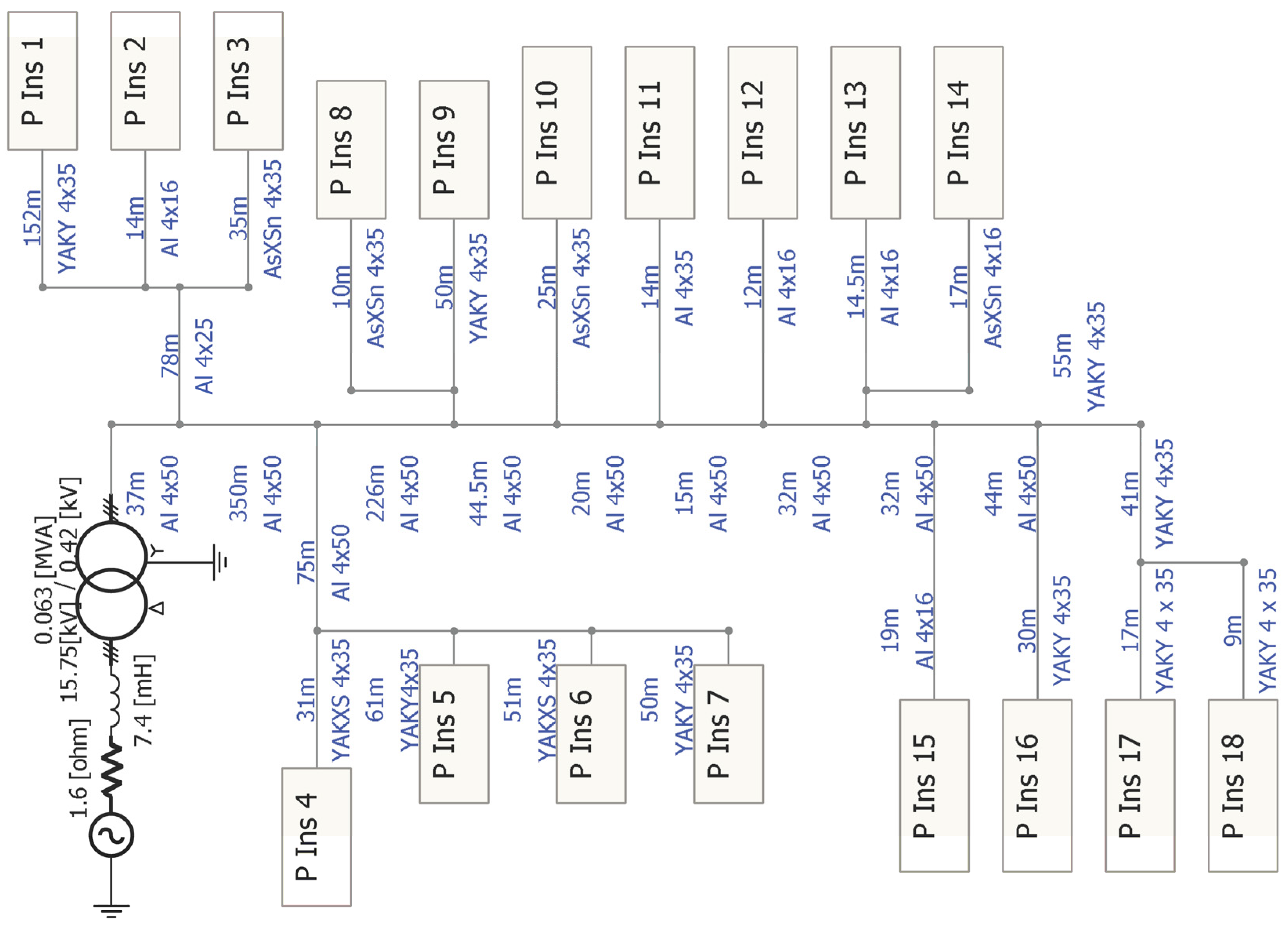
The simulation was performed using a PSCAD/EMTDC environment for an exemplary LV distribution network presented in Figure 2 (typical for rural areas in Poland), for which the main problem was the unbalance of phase voltages. An overhead line, with conductors of 50 mm2 Al, was supplied from a distribution transformer of 63 kVA, equipped with an off-load tap changer. Eighteen prosumer installations were distributed along this feeder. Each installation consisted of 2 kW, single phase PV installations connected to L1 phase (in 10 installations) and to L2 phase (in 8 installations), and single-phase loads were connected to L2 phase (in 10 installations) and L3 phase (in 8 installations). To simplify the analysis, it was assumed that the loads were linear. The load maximum power was 2 kW and changed according to the daily power consumption profile.
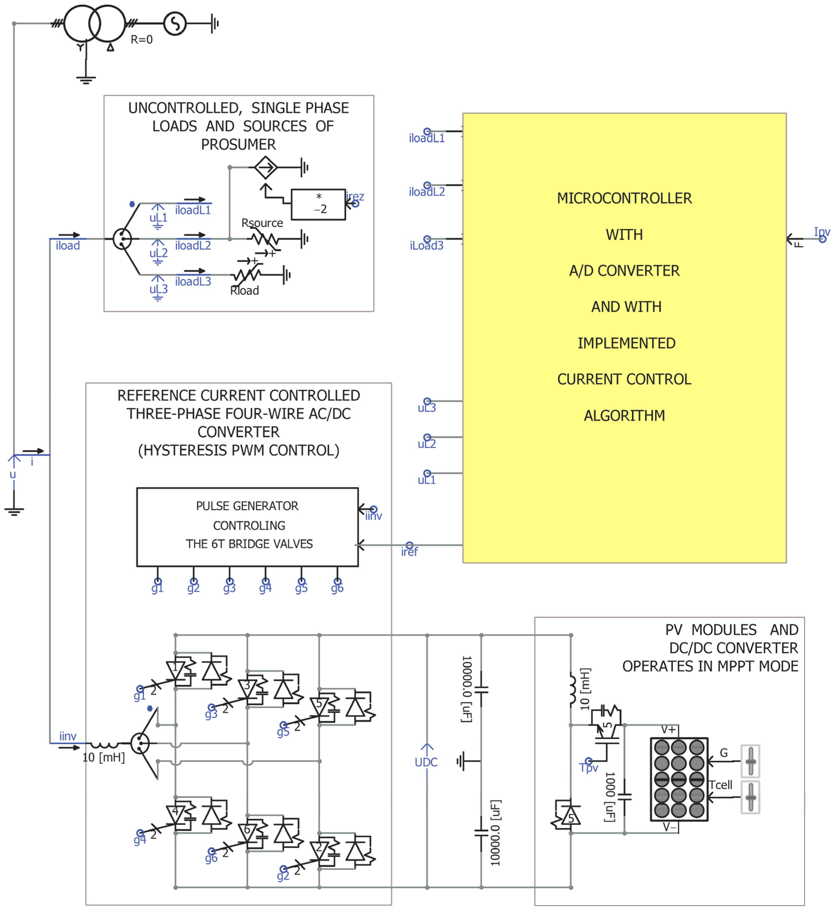
The authors propose to replace the single-phase PV inverter with three-phase sources and with the implemented control algorithm. A model of such a PV source is shown in Figure 3. It consists of a model of a photovoltaic panel with a DC/DC converter operating in MPPT mode and a three-phase four-wire AC/DC converter with a 6T bridge controlled by a pulse generator operating in PWM hysteresis mode. The phase reference current values for the pulse generator were calculated by a microcontroller with an implemented current control algorithm (described in Section 2).
The flowchart of the presented PV inverter control algorithm is presented in Figure 4.
Load and PV profiles used in simulations are shown in Figure 5.

3.2. Simulation Results

Simulations were carried out to analyze the impact of distributed PV sources in prosumer installations on the grid operation during a day. The following cases were considered to evaluate the purposefulness of using 3-phase 4-wire inverters with the proposed algorithm. The first case concerned the current status of the network, i.e., prosumer installations in which single-phase PV systems were installed. In the second case, it was assumed that the single-phase inverters were replaced with 3-phase ones. The third simulation case was applied to the 3-phase PV inverters with the proposed control algorithm implemented. Finally, in case four, the possibility of increasing the power of PV modules while using the same 3-phase inverter was checked. In each simulation case the courses of instantaneous values of phase currents in prosumer installations and in the distribution transformer, as well as phase voltages at all PCCs in the network, were determined. Then, the RMS values of current and voltages were calculated for each cycle, which formed a set of values that were analyzed.
The network with single-phase inverters in prosumer installations (case 1) was considered as a reference. For the clarity of the paper, selected results for cases 1 and 3 are presented in detail. All scenarios are compared and concluded in Table 1.

3.2.1. Simulation Results for LV Network with Single-Phase Inverters in Prosumer Installations—Reference Case

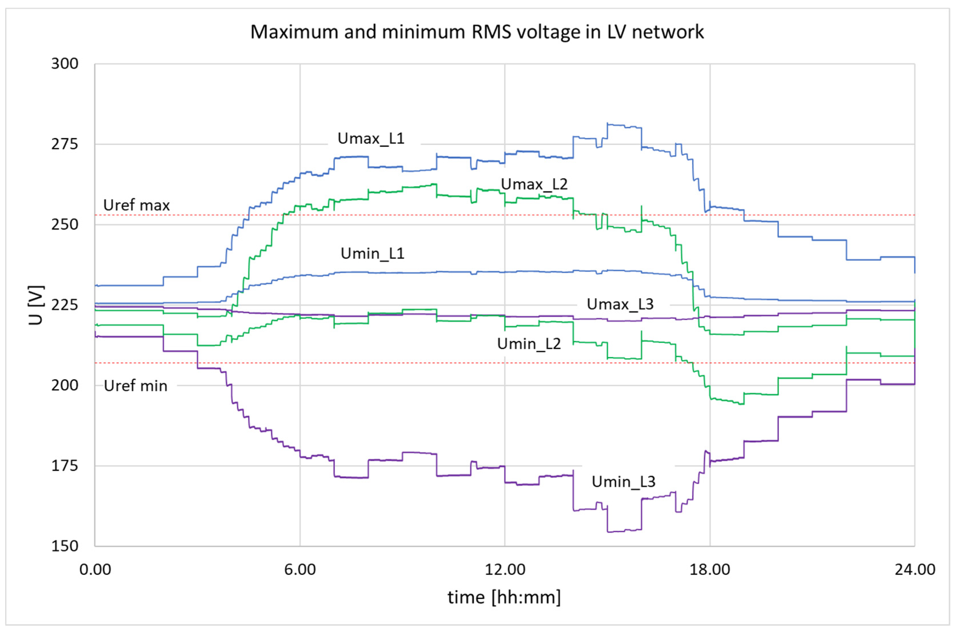
It was assumed that the load power factor was equal 1 for all prosumers. Maximum and minimum RMS voltage values were collected at network nodes during a simulated day for each phase and presented in Figure 6. The figure does not show at which node the max/min voltage occurred at a given time, but the range of voltage changes in the network can be easily observed. For the presented analysis such information is sufficient, as the scale of potential problems can be assessed. In this particular case, in the phases L1 and L2, to which the PV systems were connected, the voltages were above the acceptable upper limit of 253 V for most of the day and in the phase L3 (only with loads), were below the lower limit of 207 V. Large voltage deviations that were outside the allowable range can easily be noticed in the figure. This indicates that the operation of the network under such conditions was unacceptable both for the DSO and the prosumers.
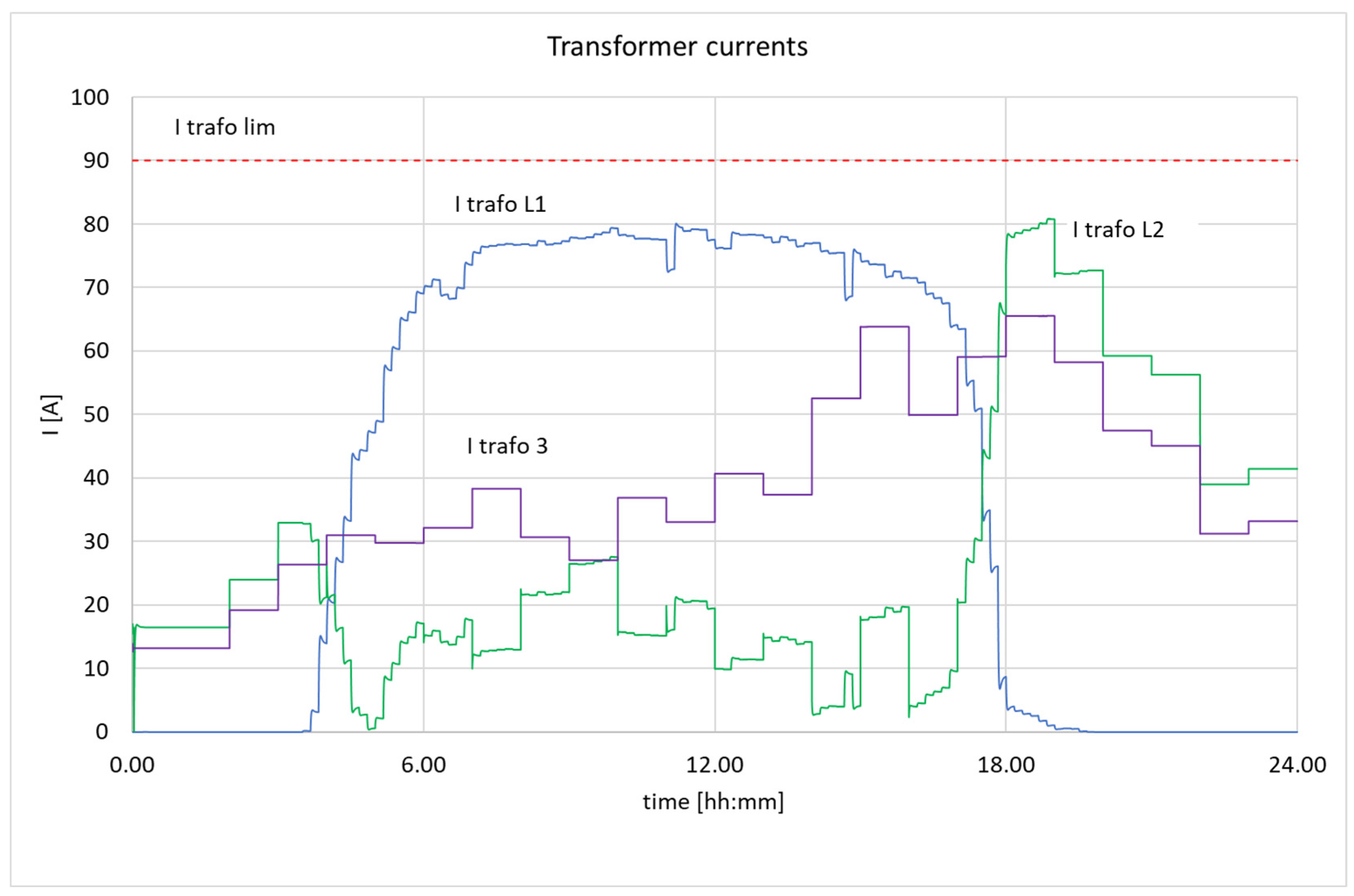
The transformer load RMS currents are illustrated in Figure 7. Although the maximum currents (90 A) were not exceeded in any phase, their high unbalance indicates suboptimal utilization of the transformer.
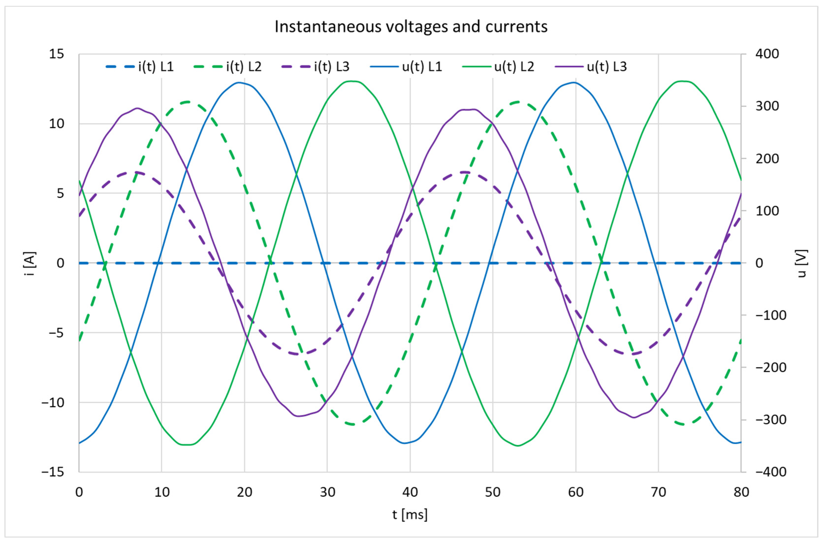
The instantaneous currents and voltages for each phase of the single prosumer installation are presented in Figure 8. This measurement started at 10:00 h of simulation. During the period presented in L1 phase the load current was 0 (there was no load and no generation), in L2 the current shifted by 180 degrees from the voltage, which was a result of single-phase PV generation, and in L3 phase the current and voltage were in phase—result of resistive load operation.

3.2.2. Simulation Results for LV Network with 3-Phase Inverters in Prosumer Installations with the Proposed Control
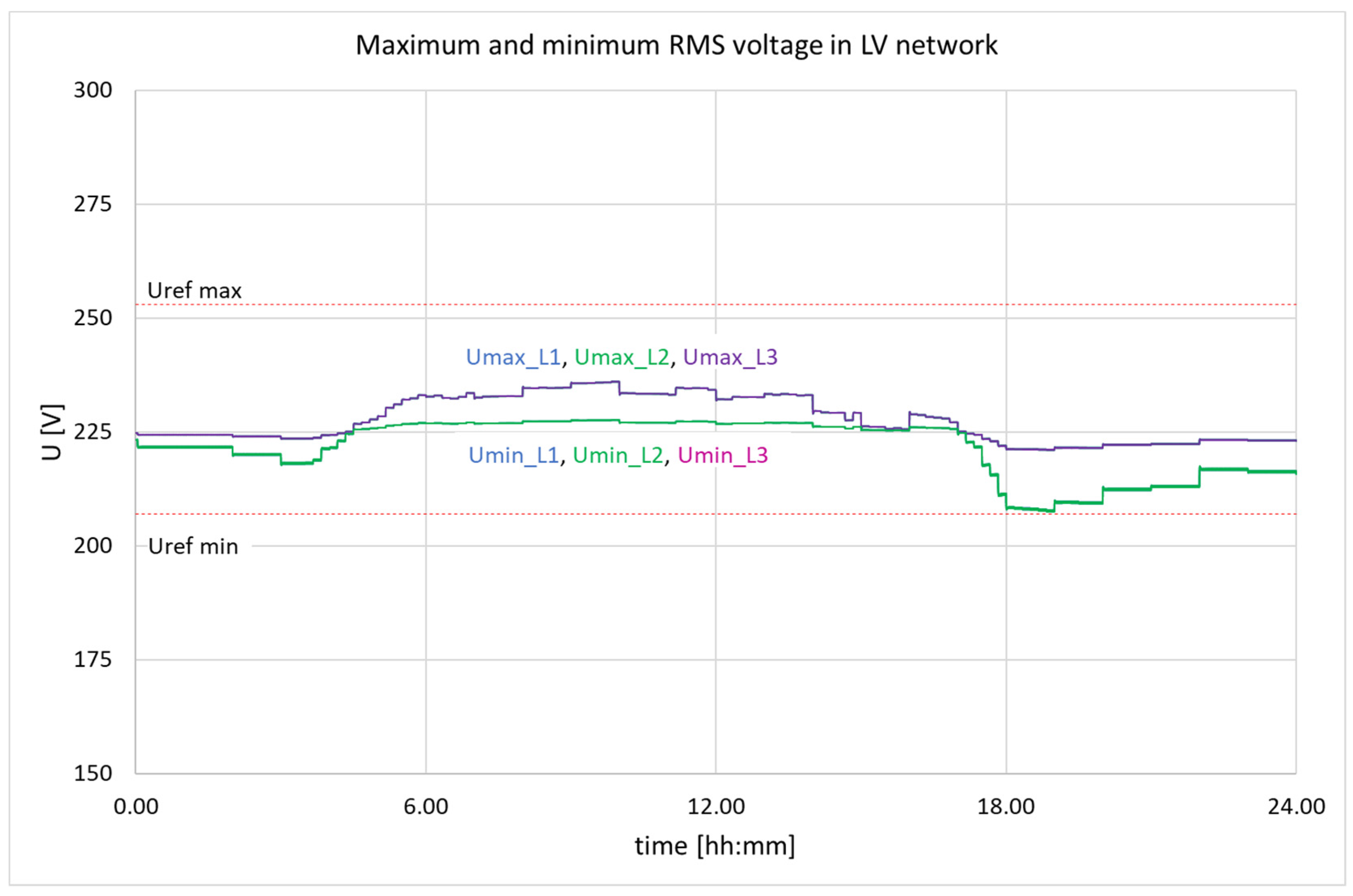
In this case, it was assumed that the single-phase PV inverters in all prosumer installations were replaced with the 3-phase 4-wire ones and the proposed control algorithm was implemented in each of them. Results of the calculations are presented in Figure 9, Figure 10 and Figure 11, respectively. As seen in Figure 9, the control algorithm significantly alleviated voltage deviations in the network. Maximum voltages oscillated between 221 V and 235 V and did not exceed the upper level of the allowable voltage range in the whole simulation period (compared to the previous case, maximum voltages ranged from 216 V to 282 V). Additionally, in the case of minimum voltages, the measured values were always above the lowest limit and varied between 208 V and 228 V (compared to the previous case, minimum voltages ranged from 155 V to 236 V).
Figure 9. Maximum and minimum phase voltages in the network for one-day simulation period, the case of 3-phase PV inverters in prosumer installations with implemented control algorithm. Lines for corresponding max and min values are overlapping.
Energies 16 03479 g009
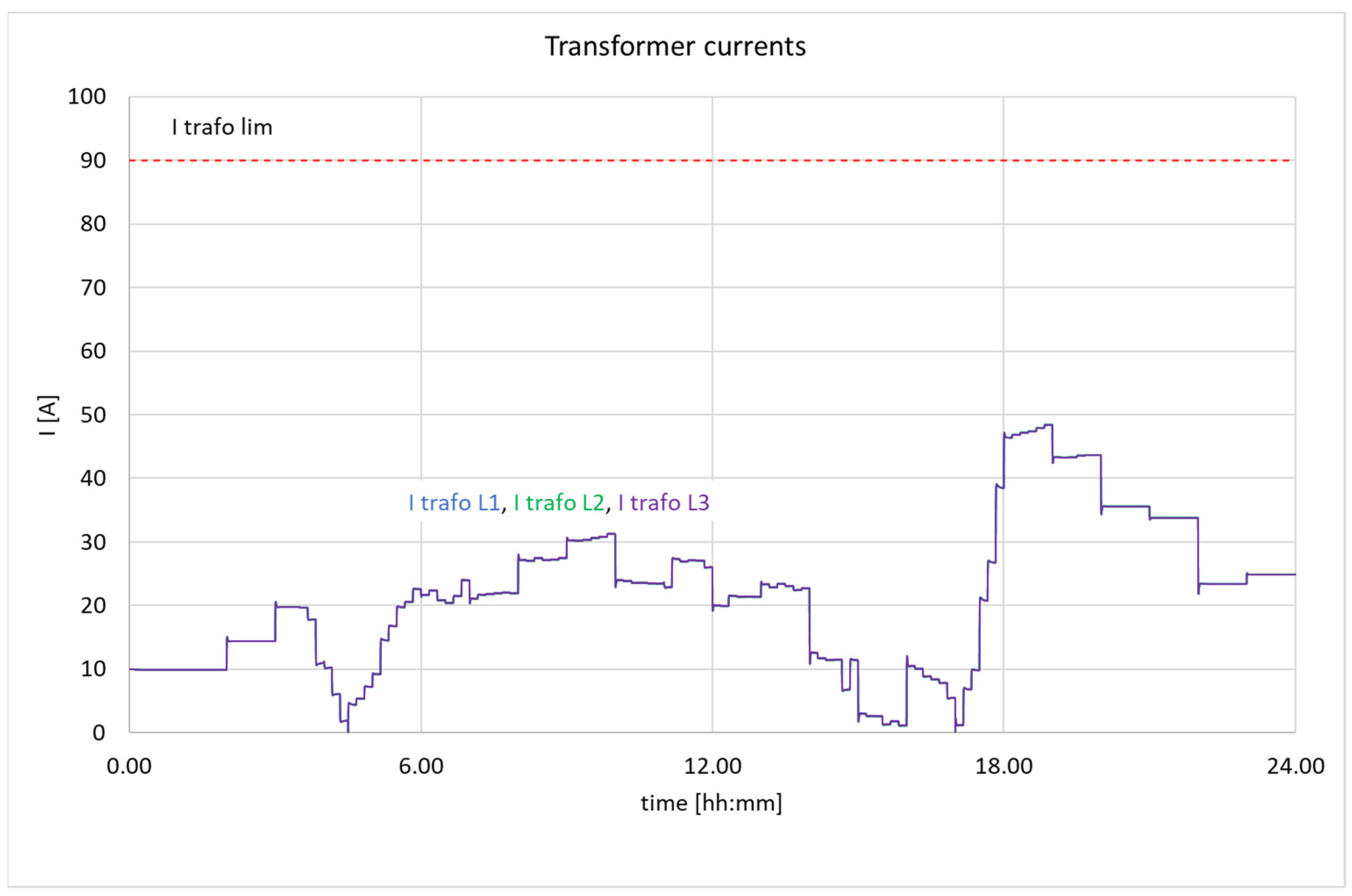
Figure 10. MV/LV transformer currents during one-day simulation, the case of 3-phase PV inverters in prosumer installations with implemented control algorithm.
Energies 16 03479 g010
Figure 11. Instantaneous currents and voltages collected in the 10th hour of simulation in a single prosumer installation, the case of three-phase PV inverters and implemented control algorithm.
Energies 16 03479 g011
With the implemented proposed control algorithm, the transformer operating conditions improved significantly. Balancing loads in individual prosumer installations resulted in balancing the transformer currents. Under such conditions, its maximum load was decreased significantly and did not exceed 50 A (Figure 10), so a significant transformer capacity was released. It can be assumed that thanks to the operation of the prosumer control algorithm, the transformer capacity was increased.
The symmetry of instantaneous currents and voltages in single prosumer installation is seen in Figure 11, which is a confirmation of the correctness of the proposed control algorithm. These measurements were extracted for the 10th hour of simulation. In contrast to the waveforms shown in Figure 6, here all currents were balanced, which resulted in symmetry of the voltages. A 180-degree shift between the currents and voltages in all phases indicates that the energy was being fed back into the grid. This is due to the high generation from the PV system at the selected time and the inability to store the surplus energy in the prosumer installation.
Table 1 summarizes the selected results of the simulations for all the cases. The meanings of the symbols used in the table are given below.
As seen in Table 1, if only single-phase PV inverters were used in prosumer installations, the voltages measured in the feeder nodes were within an unacceptable range (155 ÷ 282) V. Those are unfavorable conditions for most PCCs—the RMS voltage should be in the range of ±10% Un, which is (207 ÷ 253) V. Replacing single-phase inverters with a 3-phase one (case 2) for the PV panels of the same rated power resulted in a decrease in inverter valves loading of 64%. If this is done for all installations, voltage profiles along the feeder would be improved and the range of all calculated voltage values would narrower, i.e., (178 ÷ 272) V. However, in some nodes, the voltage may still transgress the required range. When the 3-phase inverters were applied with the proposed balancing algorithm (case 3), the voltage profiles in the feeder improved significantly. The calculated values of voltages in all nodes of the feeder were in the range of (208 ÷ 237) V, so they were within limits for any generation and load conditions. It should be noted that the coefficient of inverter valves loading in the case 3 was 0.98, so the additional balancing service did not require an increase in the PV inverters rated capacity. The effectiveness of the algorithm is also demonstrated in case 4 by the fact that, despite doubling the power of the PV installation, the voltages remained within the required range. However, in this case, it was also necessary to increase the current carrying capacity of the inverter by 30%.

4. Summary of the Proposed Method

Observations derived from the simulations can be summarized as follows. The proposed control applied in 3-phase 4-wire PV inverters in unbalanced prosumer installations ensures the transmission of power generated by PV panels and at the same time allows for the symmetrization of the phase voltages and the maintenance of their values within the permissible range. Additionally, load reactive power is compensated, which means that the currents flowing to/from the grid are balanced and pure active. This feature of the control is important from the point of view of the grid operation and contributes to the minimization of the network losses.
The control is effective and solves the most important problems DSOs face nowadays in relation to the integration of energy sources. At the same time, it can easily be implemented in practice with low costs. A comparison of the features of the developed solution with others described in the literature is presented in Table 2.

5. Conclusions

In the face of the constantly increasing number and power of PV systems installed in prosumer installations, maintaining the required voltage quality in the LV distribution grids is a real and serious challenge for DSOs. The use of single-phase PV sources distributed in different phases of the network can cause the growth of phase voltage unbalance and the exceeding of the permissible voltage levels in the network nodes. An excessive voltage rise negatively impacts network operation and poses a risk of PV inverters switching off.
This paper offers a solution for the optimal integration of PV panels in prosumer installations. It consists of the method of controlling the PV inverter, which makes the prosumer installation a controllable unit and eliminates its negative impact on the supplying grid in terms of power quality.
The main findings of the presented work are the following:
  • Development of the control algorithm for the 3-phase 4-wire PV inverter, which allows the inverter to simultaneously perform the function of an interface for PV panels and a compensator for load unbalance and reactive power in the prosumer installation;
  • Verification of the correctness of the developed algorithm using the simulation model of the real LV distribution network;
  • Examination of effectiveness of the proposed control in terms of the variability of phase voltages in the grid nodes.
The presented approach is beneficial for prosumers, as it prevents the PV inverters from shutting off. It is also beneficial for DSOs, because it helps to maintain the required power quality in the network and contributes to the reduction in energy losses and increases the network hosting capacity. The proposed method is particularly suitable for LV networks characterized by significant load unbalance, resulting from single-phase loads and sources installed in consumer/prosumer installations.
As a general conclusion it should be noted that DSO financial support for the investment costs of PV inverters, if they are to provide a network services, should be offered to prosumers. Such a mechanism would encourage prosumers to purchase inverters with a power greater than the power of PV panels themselves and the 3-phase 4-wire inverters with the proposed control algorithm could become the standard in new or modernized LV distribution networks.

Author Contributions

Conceptualization, R.M., I.W. and P.K.; methodology, R.M.; validation, R.M. and P.K.; investigation, R.M.; simulation, R.M.; writing—original draft preparation, R.M., I.W. and P.K.; writing—review and editing, I.W. and P.K.; visualization, P.K.; supervision, I.W. All authors have read and agreed to the published version of the manuscript.

Funding

This research received no external funding.

Data Availability Statement

Not applicable.

Conflicts of Interest

The authors declare no conflict of interest.

References

  1. Gabdullin, Y.; Azzopardi, B. Impacts of Photovoltaics in Low-Voltage Distribution Networks: A Case Study in Malta. Energies 2022, 15, 6731. [Google Scholar] [CrossRef]
  2. Gandhi, O.; Kumar, D.S.; Rodríguez-Gallegos, C.D.; Srinivasan, D. Review of Power System Impacts at High PV Penetration Part I: Factors Limiting PV Penetration. Sol. Energy 2020, 210, 181–201. [Google Scholar] [CrossRef]
  3. Sampath Kumar, D.; Gandhi, O.; Rodríguez-Gallegos, C.D.; Srinivasan, D. Review of Power System Impacts at High PV Penetration Part II: Potential Solutions and the Way Forward. Sol. Energy 2020, 210, 202–221. [Google Scholar] [CrossRef]
  4. Uzum, B.; Onen, A.; Hasanien, H.M.; Muyeen, S.M. Rooftop Solar PV Penetration Impacts on Distribution Network and Further Growth Factors—A Comprehensive Review. Electronics 2020, 10, 55. [Google Scholar] [CrossRef]
  5. Mukwekwe, L.; Venugopal, C.; Davidson, I.E. A Review of the Impacts and Mitigation Strategies of High PV Penetration in Low Voltage Networks. In Proceedings of the 2017 IEEE PES PowerAfrica, Accra, Ghana, 27–30 June 2017; IEEE: Piscataway, NJ, USA, 2017; pp. 274–279. [Google Scholar]
  6. Eltawil, M.A.; Zhao, Z. Grid-Connected Photovoltaic Power Systems: Technical and Potential Problems—A Review. Renew. Sustain. Energy Rev. 2010, 14, 112–129. [Google Scholar] [CrossRef]
  7. Lucas, A. Single-Phase PV Power Injection Limit Due to Voltage Unbalances Applied to an Urban Reference Network Using Real-Time Simulation. Appl. Sci. 2018, 8, 1333. [Google Scholar] [CrossRef]
  8. Brinkel, N.B.G.; Gerritsma, M.K.; AlSkaif, T.A.; Lampropoulos, I.; van Voorden, A.M.; Fidder, H.A.; van Sark, W.G.J.H.M. Impact of Rapid PV Fluctuations on Power Quality in the Low-Voltage Grid and Mitigation Strategies Using Electric Vehicles. Int. J. Electr. Power Energy Syst. 2020, 118, 105741. [Google Scholar] [CrossRef]
  9. De Silva, H.H.H.; Jayamaha, D.K.J.S.; Lidula, N.W.A. Power Quality Issues Due to High Penetration of Rooftop Solar PV in Low Voltage Distribution Networks: A Case Study. In Proceedings of the 2019 IEEE 14th International Conference on Industrial and Information Systems: Engineering for Innovations for Industry 4.0, ICIIS 2019—Proceedings 2019, Peradeniya, Sri Lanka, 18–20 December 2019; pp. 395–400. [Google Scholar] [CrossRef]
  10. Kharrazi, A.; Sreeram, V.; Mishra, Y. Assessment Techniques of the Impact of Grid-Tied Rooftop Photovoltaic Generation on the Power Quality of Low Voltage Distribution Network—A Review. Renew. Sustain. Energy Rev. 2020, 120, 109643. [Google Scholar] [CrossRef]
  11. Miller, W.; Liu, A.; Amin, Z.; Wagner, A. Power Quality and Rooftop-Photovoltaic Households: An Examination of Measured Data at Point of Customer Connection. Sustainability 2018, 10, 1224. [Google Scholar] [CrossRef]
  12. Ostrowska, A.; Michalec, Ł.; Skarupski, M.; Jasiński, M.; Sikorski, T.; Kostyła, P.; Lis, R.; Mudrak, G.; Rodziewicz, T. Power Quality Assessment in a Real Microgrid-Statistical Assessment of Different Long-Term Working Conditions. Energies 2022, 15, 8089. [Google Scholar] [CrossRef]
  13. Chamier-Gliszczynski, N.; Trzmiel, G.; Jajczyk, J.; Juszczak, A.; Woźniak, W.; Wasiak, M.; Wojtachnik, R.; Santarek, K. The Influence of Distributed Generation on the Operation of the Power System, Based on the Example of PV Micro-Installations. Energies 2023, 16, 1267. [Google Scholar] [CrossRef]
  14. Wang, X.; Wang, L.; Kang, W.; Li, T.; Zhou, H.; Hu, X.; Sun, K. Distributed Nodal Voltage Regulation Method for Low-Voltage Distribution Networks by Sharing PV System Reactive Power. Energies 2022, 16, 357. [Google Scholar] [CrossRef]
  15. Almeida, D.; Pasupuleti, J.; Ekanayake, J. Comparison of Reactive Power Control Techniques for Solar PV Inverters to Mitigate Voltage Rise in Low-Voltage Grids. Electronics 2021, 10, 1569. [Google Scholar] [CrossRef]
  16. Ariyaratna, P.; Muttaqi, K.M.; Sutanto, D. A Novel Control Strategy to Mitigate Slow and Fast Fluctuations of the Voltage Profile at Common Coupling Point of Rooftop Solar PV Unit with an Integrated Hybrid Energy Storage System. J. Energy Storage 2018, 20, 409–417. [Google Scholar] [CrossRef]
  17. Rafał, K.; Biskupski, J.; Bykuć, S.; Chaja, P. Dynamic Voltage Regulation and Unbalance Compensation in a Low-Voltage Distribution Network Using Energy Storage System. Appl. Sci. 2022, 12, 11678. [Google Scholar] [CrossRef]
  18. Mieński, R.; Urbanek, P.; Wasiak, I. Using Energy Storage Inverters of Prosumer Installations for Voltage Control in Low-Voltage Distribution Networks. Energies 2021, 14, 1121. [Google Scholar] [CrossRef]
  19. Ghasemi, M.A.; Parniani, M. Prevention of Distribution Network Overvoltage by Adaptive Droop-Based Active and Reactive Power Control of PV Systems. Electr. Power Syst. Res. 2016, 133, 313–327. [Google Scholar] [CrossRef]
  20. Gerdroodbari, Y.Z.; Razzaghi, R.; Shahnia, F. Decentralized Control Strategy to Improve Fairness in Active Power Cur-tailment of PV Inverters in Low-Voltage Distribution Networks. IEEE Trans. Sustain. Energy 2021, 12, 2282–2292. [Google Scholar] [CrossRef]
  21. Carpinelli, G.; Mottola, F.; Proto, D.; Varilone, P. Minimizing Unbalances in Low-Voltage Microgrids: Optimal Scheduling of Distributed Resources. Appl. Energy 2017, 191, 170–182. [Google Scholar] [CrossRef]
  22. Wasiak, I.; Szypowski, M.; Kelm, P.; Mieński, R.; Wędzik, A.; Pawełek, R.; Małaczek, M.; Urbanek, P. Innovative Energy Management System for Low-Voltage Networks with Distributed Generation Based on Prosumers’ Active Participation. Appl. Energy 2022, 312, 118705. [Google Scholar] [CrossRef]
  23. Buła, D.; Jarek, G.; Michalak, J.; Zygmanowski, M. Control Method of Four Wire Active Power Filter Based on Three-Phase Neutral Point Clamped T-Type Converter. Energies 2021, 14, 8427. [Google Scholar] [CrossRef]
  24. Ucar, M.; Ozdemir, E.; Kale, M. An Analysis of Three-Phase Four-Wire Active Power Filter for Harmonic Elimination Reactive Power Compensation and Load Balancing under Non-Ideal Mains Voltage. In Proceedings of the PESC Record—IEEE Annual Power Electronics Specialists Conference, Aachen, Germany, 20–25 June 2004; Volume 4, pp. 3089–3094. [Google Scholar] [CrossRef]
  25. Maciel, L.F.A.; Morales, J.L.M.; Gaona, D.C.; Pimentel, J.G.M. A Study of a Three-Phase Four-Wire Shunt Active Power Filter for Harmonics Mitigation. In Proceedings of the 2018 IEEE International Autumn Meeting on Power, Electronics and Computing ROPEC, Ixtapa, Mexico, 14–16 November 2018. [Google Scholar] [CrossRef]
  26. Vivek, P.; Muthuselvan, N.B. Investigation on Photovoltaic System Based Asymmetrical Multilevel Inverter for Harmonic Mitigation. In Proceedings of the 7th International Conference on Electrical Energy Systems, ICEES, Chennai, India, 11–13 February 2021; pp. 334–339. [Google Scholar] [CrossRef]
  27. Khaledian, A.; Vahidi, B.; Abedi, M. Harmonic Distorted Load Control in a Microgrid. J. Appl. Res. Technol. 2014, 12, 792–802. [Google Scholar] [CrossRef]
  28. Salmerón, P.; Herrera, R.S.; Vázquez, J.R. A New Approach for Three-Phase Loads Compensation Based on the Instanta-neous Reactive Power Theory. Electr. Power Syst. Res. 2008, 78, 605–617. [Google Scholar] [CrossRef]
  29. Pires, V.F.; Cordeiro, A.; Foito, D.; Pires, A.J.; Hao, C.; Martins, J.F.; Castro, R. Compensation of Unbalanced Low-Voltage Grids Using a Photovoltaic Generation System with a Dual Four-Leg, Two-Level Inverter. Electronics 2022, 11, 320. [Google Scholar] [CrossRef]
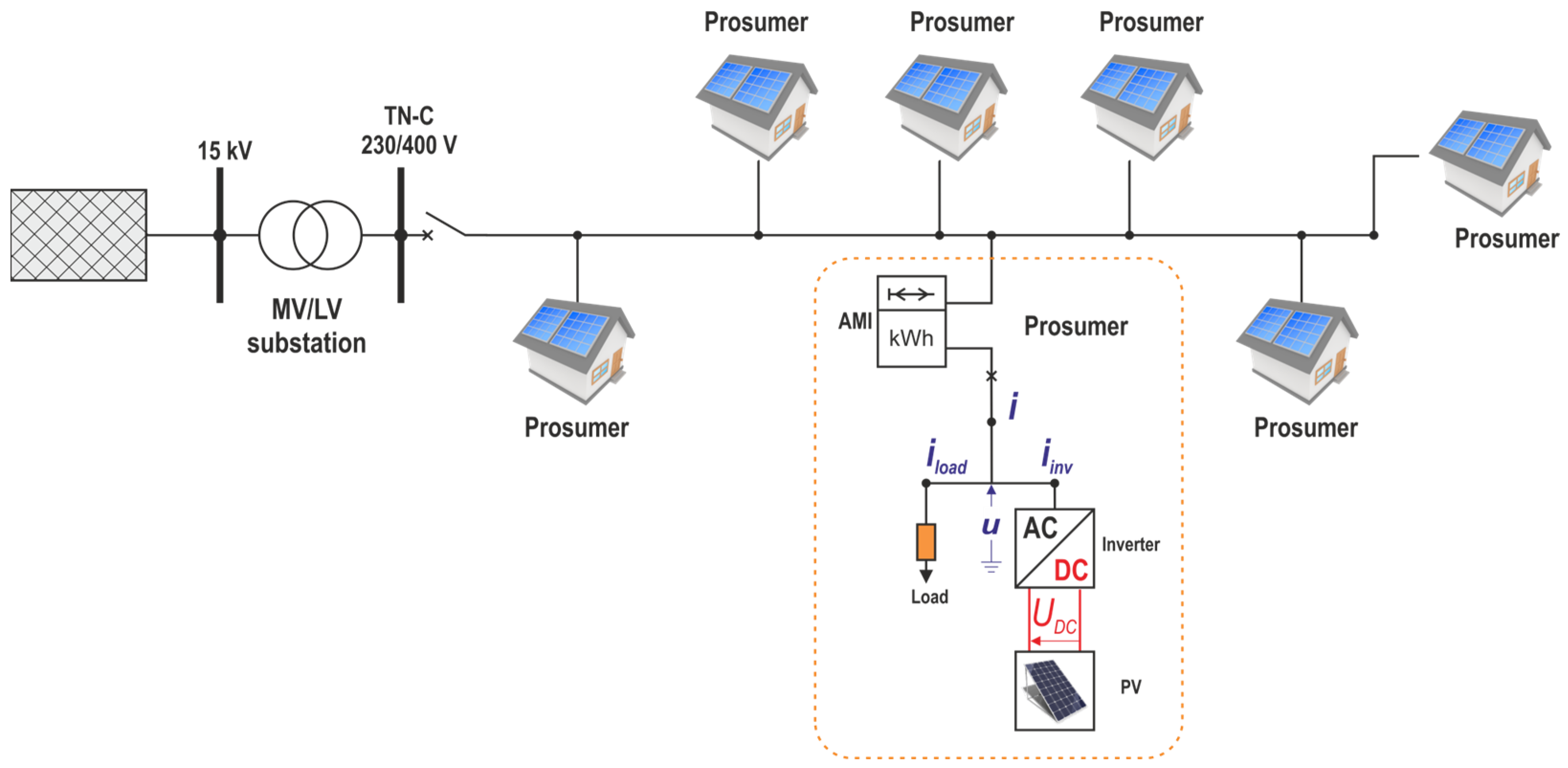
Figure 1. Diagram of a prosumer installation coupled with a distribution network.
Energies 16 03479 g001
Figure 2. LV distribution network under consideration modelled in PSCAD/EMTDC environment. Prosumer installations (P Ins) were numbered from 1 to 18.
Energies 16 03479 g002
Figure 3. Diagram of prosumer installation with PV inverter controlled by the proposed algorithm.
Energies 16 03479 g003
Figure 4. The flowchart of the inverter control algorithm.
Energies 16 03479 g004
Figure 5. Load and PV profiles used in the simulation.
Energies 16 03479 g005
Figure 6. Maximum and minimum phase voltages in the network for one-day simulation period, reference case.
Energies 16 03479 g006
Figure 7. MV/LV transformer currents during one-day simulation, reference case.
Energies 16 03479 g007
Figure 8. Instantaneous currents and voltages collected in the 10th hour of simulation in a single prosumer installation, reference case.
Energies 16 03479 g008
Table 1. Comparison of simulation results.
Case NumberProsumer InstallationDistribution Network
PV InverterBalancing
Algorithm
Implemented
Inverter Valves Load CoefficientTransformer Voltages at PCCs
PnTypeIrmsUmaxUmin
-[kW]---[A][V][V]
121-phaseNo187282155
223-phaseNo0.3682272178
323-phaseYes0.9850237208
443-phaseYes1.380252208
Max Irms means the maximum value from the set of measured phase RMS currents. Inverter valves load coefficient is the max inverter Irms measured in each case related to max Irms measured for the reference case (single phase inverter). Umax and Umin mean the maximum/minimum values from the set of phase RMS voltages measured for all prosumer installations.
Table 2. Comparison of solutions used to improve operating parameters of LV networks.
FeaturePV Inverters
[14,15,20,22]
ESSs
[16,17,18,22]
Static
Compensators
[23,24,25]
PV Inverters with the Proposed Control
Application
effects
  • Mitigation of overvoltages at the PCC
  • Voltage balancing
  • Voltage balancing at the PCC
  • Load currents balancing
  • Harmonic currents compensation
  • Indirect voltage improvement at the PCC
  • Transmission of P generated by PV panels
  • Balancing loads currents.
  • Indirect voltage improvement at the PCC
  • Q compensation
Algorithm complexity
  • Simple
  • Relatively simple
  • More complex
  • Simple
Impact on the grid
  • Local
  • Necessary coordination in more extensive control systems to ensure appropriate voltage values in the whole grid
  • Local
  • Necessary coordination in more extensive control systems to ensure appropriate voltage values in the whole grid
  • Local
  • Local
  • It ensures appropriate voltage values in the whole grid (without any coordination needed) if applied in all prosumer installations
  • It ensures minimum power and energy losses if applied in all prosumer installations
Implementation costs
  • No additional costs for controllable PV inverters
  • Additional cost of losses in the grid due to the increase flow of reactive power
  • High costs of device
  • Additional cost of losses in the network due to increase of active and reactive power flow
  • Costs of controllers and communication, if applied in centralized systems
  • High
  • Low
Strengths
  • No additional costs and efforts are required if 3-phase controllable inverters are used
  • Better use of ESS—PQ control as an ancillary service
  • Good effectiveness
  • Versatility in disturbances compensation
  • Best use of prosumer infrastructure
  • No additional costs,
  • Profitability for DSO and prosumers
Weaknesses
  • Limited effective-ness with Q regulation due to high R/X ratio in LV grids
  • Loss of renewable energy that could not be produced if generation of active power was curtailed
  • Possible interference with the main function if PQ functionality is an ancillary service
  • Additional costs of communication and complex control in coordinated centralized systems
  • Effects limited to a single disturbing load device
  • The best effect on the grid can be achieved if PV inverters with the proposed control are applied in all prosumer installations
Disclaimer/Publisher’s Note: The statements, opinions and data contained in all publications are solely those of the individual author(s) and contributor(s) and not of MDPI and/or the editor(s). MDPI and/or the editor(s) disclaim responsibility for any injury to people or property resulting from any ideas, methods, instructions or products referred to in the content.