Article

Simulation and Experimental Study on the Use of Ventilation Air for Space Heating of a Room in a Low-Energy Building

Department of Power Systems and Environmental Protection Facilities, Faculty of Mechanical Engineering and Robotics, AGH University of Science and Technology, Mickiewicza 30, 30-059 Kraków, Poland
Energies 2023, 16(8), 3456; https://doi.org/10.3390/en16083456
Submission received: 14 March 2023 / Revised: 11 April 2023 / Accepted: 12 April 2023 / Published: 14 April 2023
(This article belongs to the Special Issue Energy Performance, Management and Recovery in Buildings)

Abstract

:
In thermally modernised buildings, sharing of ventilation heat loss becomes more significant. In the case of the application of ventilation with heat recovery, especially during transitional periods, there arises a question of whether an air system makes it possible to maintain the required indoor air temperature without the necessity of using a basic hydronic heating system. This paper presents the application of a simple thermal network model of a building zone to simulate indoor air temperature in a single room of a multi-storey building with a mechanical ventilation system with heat recovery. Ventilation air was supposed to be the only heat source and its ability to maintain the required indoor air temperature was checked in simulations and then compared with measurements. The 5R1C thermal network model of a building zone was used for simulations. Comparison with measurements showed the Mean Absolute Error (MAE) and Root Mean Square Error (RMSE) of indoor air calculation to be 2.37 °C and 2.45 °C, respectively. When including heat flux from the bottom storey through the floor, MAE = 1.28 °C and RMSE = 1.38 °C were obtained.

1. Introduction

A dominating share of total energy use in Polish residential buildings belongs to space heating [1]. Therefore, thermal refurbishment of buildings in Poland has focused, so far, mainly on external walls, roofs, and windows [2,3,4]. However, in thermally modernised objects, the energy required to warm up cold external air supplied to the building’s interior is more important [5,6,7]. For this reason, various solutions of ventilation heat recovery are applied both in new and thermally modernised buildings [8,9,10] resulting in lower heating energy demand [11,12,13,14].
At the design stage of each thermal refurbishment, the design heat load is calculated following the procedure provided in EN 12831 [15,16] for the external design temperature given in that standard. It depends on the climatic conditions of the area of interest [17]. The efficiency of the ventilation heat recovery, assumed by the system’s designer, is also taken into account [18]. The calculated design load is the minimum thermal power that has to be supplied to the building zone to ensure thermal comfort during the heating season [19]. However, one should remember that the design external air temperature is an extreme value that may occur only for a short period of time in the year. Hence, the designed thermal power is not utilised permanently, which can be noticed in any thermal load duration curve of a single building or a heating network [20]. For two or more installed heat sources, this means the possibility to choose the most effective one in certain conditions. Therefore, in a building with a hydronic heating system and ventilation with heat recovery, there is a possibility to use only the latter under favourable outdoor weather conditions. It can be especially interesting in buildings after thermal retrofitting or in other energy efficient objects.
Numerous studies confirmed good indoor conditions in buildings with air handling units with cooling and heating coils combined with various, both low- and high-temperature, hydronic heating systems [21,22,23,24]. Several authors have also presented relevant case studies recently.
Harsem et al. [25] proposed a heating system for a hospital consisting of a ground source heat pump, gas boiler, borehole thermal energy storage, hydronic radiators, and an air handling unit. Calculations, performed in a developed simulation tool, allowed the selection of thermal capacity of heat pumps for their highest seasonal performance effectiveness. The authors also studied the impact of ventilation heat recovery efficiency and ventilation coil supply/return temperatures on the annual effectiveness of a system.
Javed et al. [26] studied an application of displacement ventilation to provide heating to a passive school building located in Norway. At first, experimental tests in a test cell and simulations in the IDA-ICE tool were performed to ensure that the simulation program is capable of computing thermal and contaminant stratification in a room with displacement ventilation. Field tests in the classroom revealed that the ventilation system was able to maintain an indoor operative temperature within the acceptable comfort range during winter conditions (outdoor temperature from −7 °C to +3 °C).
Mao et al. [27] presented an application of stratum ventilation for space heating in a single room. Using CFD simulations in the Airpak 3.0.16 tool, they analysed the impact of room dimensions on air distribution, thermal comfort, and ventilation performance, obtaining the maximum suitable dimensions for the room. Temperature effectiveness of ventilation and dimensionless temperature were used as energy efficiency indicators of heating. Experiments in a test room confirmed the accuracy of simulations.
Ameen et al. [28] experimentally studied the usability of a corner-placed stratum ventilation system to provide cooling and heating in a medium test room. A total of 15 cases with three nominal supply air temperature setpoints of 17.7 °C, 21 °C, and 25 °C and five different airflow rates from 30 to 70 L/s were investigated. The measured vertical temperature gradients and the velocity conditions satisfied the requirements of Category A of ISO7730 in all cases. Similar conclusions were given in the case of corner-impinging jet ventilation, corner-mixing ventilation, and displacement ventilation in the cooling and heating modes [29,30].
Kong et al. [31] investigated mixing and stratum ventilation for space heating in a test chamber. Experimental results confirmed good energy performance of stratum ventilation while maintaining required indoor thermal conditions. Ventilation effectiveness was also higher in this case: 0.98 in comparison to 0.74 for mixing ventilation.
In a simulation study [32], authors simulated in TRNSYS the use of exhaust ventilation air and the air-to-water compressor heat pump for space heating of a multifamily building. The proposed solution showed its potential for energy consumption reduction in five analysed locations in Poland. However, indoor comfort was not studied.
The presented studies proved the ability of ventilation to provide space heating while maintaining indoor thermal comfort during the heating season. Several authors noticed that this concept fits well with low-energy and passive houses [33,34,35,36]. However, the focus on the technical aspects of ventilation has made the issue of the building’s heat balance and thermal dynamics recede into the background.
While considering the use of ventilation for space heating of a building, mainly professional and sophisticated simulation tools were used such as IDA ICE in the case of a municipal building [37,38,39]. Markiewicz-Zahorski et al. [40] analysed the conversion of an office building into a multi-family residential building based on monthly and hourly energy simulations in OZC and EnergyPlus simulation tools, respectively. Ventilation loss was included in the energy demand for space heating and cooling, but no information on considered ventilation systems was provided. Veršić et al. [41] simulated night passive cooling in an office building depending on the wind velocity using the building model of 3D Studio MAX 2016 and CFD Simscale software. Hourly energy simulations were performed implementing the hourly method of EN ISO 52016-1 [42] in Visual Basic 2017. Authors not only analysed indoor thermal conditions but estimated cooling energy savings as well. They also presented selected waveforms of hourly indoor and outdoor air temperature, wind speed, and cooling load.
A simpler solution was used in [43] for the simulation of the hourly internal air temperature in a free-running building with a double skin façade. For this application, authors accordingly modified the 5R1C (five resistors and one capacitor) thermal network model of a building zone from EN ISO 13790 [44]. It is intended only for the calculation of sensible heating and cooling power, so the humidification and dehumidification processes of air cannot be considered here.
That standard has been replaced recently by EN ISO 52016 [42] which, among others, introduced a more detailed hourly simulation method [45]. However, despite its complexity, authors reported differences in output results between this new method and more sophisticated professional simulation tools [46,47,48]. Hence, it was decided to apply the simpler method of EN ISO 13790, still used in practice [49,50].
This model is of special interest because of several important advantages, such as low computational requirements [51,52,53], allowing it to be implemented in a spreadsheet [54,55], and easy modification for various applications [56,57,58,59]. Despite the used simplifications, such as lumping all partitions into single thermal capacitance, it provides reliable results [60].
Thanks to these features, it was also used in studies related to various aspects of ventilation in buildings. Costantino et al. [61] analysed the indoor climate in broiler houses and the required ventilation flow rate dependent on the broiler’s age. Hedegaard et al. [62] simulated the district heating consumption of large groups of residential buildings. Natural ventilation in the 5R1C network was modelled by infiltration and window opening by occupants. The latter component was described by a relationship between the outdoor air temperature and the window openings. In [63], energy use in mechanically ventilated greenhouses was modelled. The 5R1C scheme was applied to solve the sensible energy balance and then indoor air humidity was computed. Depending on the resulting thermal conditions, various ventilation strategies of a greenhouse were introduced. Buonomano et al. [64] modified the model to simulate the behaviour of a building with integrated solar thermal collectors. The building’s occupancy schedule assumed two values of ventilation airflow depending on the season and indoor temperature. Jędrzejuk and Rucińska [1] proposed a method to assess the need for artificial cooling of residential buildings. It was based on hourly indoor operative temperature, calculated by the 5R1C model, and then compared with the defined limit.
Two conclusions emerge from the review presented. Firstly, the assessment of ventilation use for space heating was simulated using mainly professional and sophisticated tools. They are accurate but too time-consuming, especially at the stage of quick preliminary calculations. Secondly, dynamic simulations, especially hourly, can be performed with the simple but well-founded 5R1C model. However, so far, studies on space heating by ventilation with the use of this model have not been presented.
This paper aims to fill this gap by presenting a case study based on simulation and measurements taken in a single room in a building that was thermally refurbished to the low-energy standard.
The next section presents the thermal model of a building zone used for simulations and the experimental setup used during the measurement campaign. Then, statistical indicators used for the evaluation of the model’s ability to simulate indoor air temperature are given. In Section 3, detailed results of the measurements and simulations are presented. Finally, concluding remarks are given.

2. Materials and Methods

2.1. The 5R1C Model

The 5R1C thermal network model of a building zone is composed of five thermal conductances and a single capacitor and is presented in Figure 1.
There are distinguished two kinds of building partitions in that circuit. The first group, included in the Htr,w thermal transmission coefficient, consists of thermally “light” building elements (doors, windows, curtain walls, and glazed walls). The second one includes thermally “heavy” elements (walls, ceilings), which are described by the external (Htr,em) and the internal (Htr,ms) parts connected to the thermal capacity (Cm), representing the thermal mass of the building [65].
The external air temperature is modelled by the Te source. The Tsup source is the supply air temperature, which is connected to the heat transfer by ventilation (Hve). The indoor air temperature is represented by Ti and is connected through the coupling conductance Htr,is with the central node (Ts).
This model is intended for computations in hourly time steps. As a result, the hourly sensible heating or cooling power required to maintain a certain set-point indoor air or indoor operative temperature, φHC, is obtained. This procedure has been presented recently [58,66,67]. Each time step begins with the calculation of heat fluxes due to internal sources (φint) and solar irradiance (φsol), which are divided into three components: φia, φst, and φm, connected to the indoor air, central, and thermal mass temperature nodes, respectively. These components are obtained from the following relationships:
ϕ ia = 0.5 ϕ int ,
ϕ m = A m A t 0.5 ϕ int + ϕ sol ,
ϕ st = 1 A m A t H tr , w 9.1 A t 0.5 ϕ int + ϕ sol .
The solution of the network is based on the Crank–Nicholson scheme. The resulting nodal temperatures Ti and Ts are averages for one hour. The thermal mass temperatures Tm,t and Tm,t−1 are instantaneous values at time t and t−1, respectively. Tm,t is given by the equation:
T m , t = T m , t 1 C m 3600 H tr , 3 + H tr , em 2 + ϕ m , tot C m 3600 + H tr , 3 + H tr , em 2 ,
where:
ϕ m , tot = ϕ m + H tr , em T e + H tr , 3 H tr , 2 ϕ st + H tr , w T e + H tr , 1 ϕ ia + ϕ HC H ve + T sup ,
with:
H tr , 1 = 1 / 1 / H ve + 1 / H tr , is
H tr , 2 = H tr , 1 + H tr , w
and:
H tr , 3 = 1 / 1 / H tr , 2 + 1 / H tr , ms .
When considering a zone that has to be heated only by ventilation air and ventilation airflow is known, then φHC = 0 should be assumed.
The ventilation heat transfer coefficient is computed from the relationship:
H ve = ϱ a · c a · q ve ,
with the volumetric heat capacity of air is assumed to be constant at ρaca = 1200 J/m3K according to EN ISO 13790. However, both ventilation air density and specific heat capacity may vary following outdoor environmental conditions [68,69].
Finally, average hourly values of nodal temperatures are as follows:
T m = T m , t + T m , t + 1 / 2 ,
T s = H tr , ms T m + ϕ st + H tr , w T e + H tr , 3 H tr , 2 H tr , 1 ϕ ia + ϕ HC H ve + T sup H tr , ms + H tr , w + H tr , 1 ,
and the internal air temperature:
T i = H tr , ms T m + H ve T sup + ϕ ia + ϕ HC H tr , is + H ve .
In addition, based on the circuit diagram from Figure 1 and Equation (9), the ventilation heat flux can be also computed:
ϕ ve = H ve · T sup T i .

2.2. Experimental Setup

Measurements were conducted from 22 December 2021 to 3 January 2022 in a single room in one of the student dormitories in Kraków (south Poland). The whole building was thermally modernised in the year 2017. Its main heating system consists of hydronic radiators connected to the district heating network. That system was sized following the EN 12831 standard and, for the considered room, the design heating load is φHL = 366 W at the design outdoor and indoor air temperatures of −20 °C and 20 °C, respectively. This radiator was turned off during the experiment.
The balanced mechanical ventilation system supplies ventilation air to living spaces. The design ventilation airflow rate of 40 m3/s was assumed for the analysed room. The design supply ventilation air temperature Tsup = 22 °C throughout the year. The air handling unit’s heating coil is supplied by the central heating system. The heating water with design supply and return temperature of 60 °C and 40 °C, respectively, is supplied from the heat exchanger connected to the district heating network.
The selected room was on a rectangular plane of 4.0 m × 2.7 m with a height of 2.50 m (Figure 2a). The total internal volume of the room (27 m3) can be reduced by the enclosed furniture, i.e., by 4.84 m3. The locations of the sensors in the room are given in Figure 2b. The external wall with windows was east-oriented, which minimised the impact of solar irradiance.
In the experiment, four heat flux sensors were used: two on the inside surface of the external wall and two on the floor. Because of low expected values of output signals from these sensors, following manufacturer recommendations, they were connected in series in relevant pairs to logger inputs: q1 + q2 and q3 + q4 for the floor and for the external wall, respectively.
Global solar irradiance incident on the external wall was measured by the CMP11 Kipp & Zonen pyranometer. Pt100 and Pt1000 platinum resistance sensors were used for the measurement of indoor air (4 sensors: Ti1, Ti2, Ti3, and Ti4), floor surface (2 sensors: Tf1 and Tf2), internal surface of walls (2 sensors: Tw1 and tw2), ventilation air (Tsup), and external air (Te) temperatures. For air temperature measurements, sensors with low emissivity sheaths were used to minimise the impact of heat transfer by radiation. A globe thermometer with a Pt100 measured the mean radiant temperature at the height of 1.2 m above the floor (Figure 3a). Because of the number of sensors, two data loggers were used: MS6D (Comet) and RSG30 (Endress+Hauser). The measured data were recorded in 10 min intervals. The main parameters of all sensors are listed in Table 1. The ventilation airflow rate was checked several times during the study using a Testo 417 anemometer with an additional air cone (Figure 3b).
Additionally, for sky temperature measurement, the IR thermometer based on an MLX90614 sensor was applied [70]. Numerous studies confirmed its ability for non-contact temperature measurements of temperature in various environmental and building-related applications [71,72]. It has a typical accuracy of ±0.5 °C and a measurement range for object temperature from −70 °C to 380 °C and for sensor temperature from −40 °C to 125 °C.

2.3. Evaluation of the Model

To assess the model’s ability to simulate indoor air temperature under the assumed operating conditions of the heating and ventilation system, statistical analysis was performed using several basic indicators such as the mean absolute error (MAE), the root mean square error (RMSE), the mean square error (MSE), and the coefficient of determination (R2) [73,74,75,76,77].
Assuming that xi is its actual (reference) value of a given physical quantity, x, taken from measurements and  x ^ i  is its value predicted by the model,  x ¯ i  is the average reference value of x and n is the total number of samples, then it can be written that the aforementioned metrics are given by the following relationships:
MAE = i = 1 n x ^ i x i n ,
RMSE = i = 1 n x ^ i x i 2 n ,
MSE = i = 1 n x ^ i x i 2 n ,
R 2 = 1 i = 1 n x i x ^ i 2 i = 1 n x i x ¯ 2 .

3. Results and Discussion
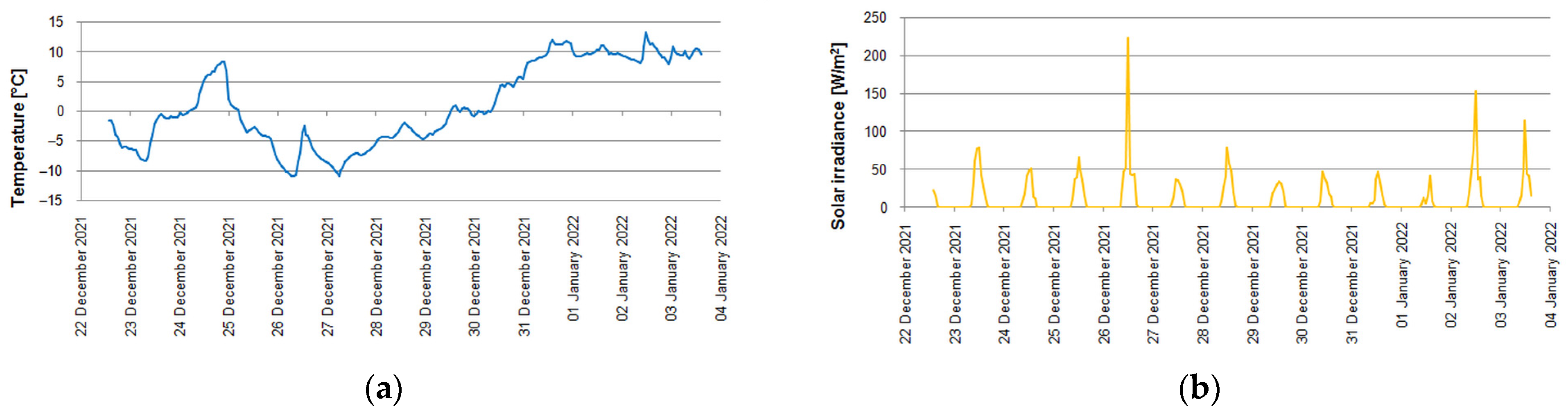
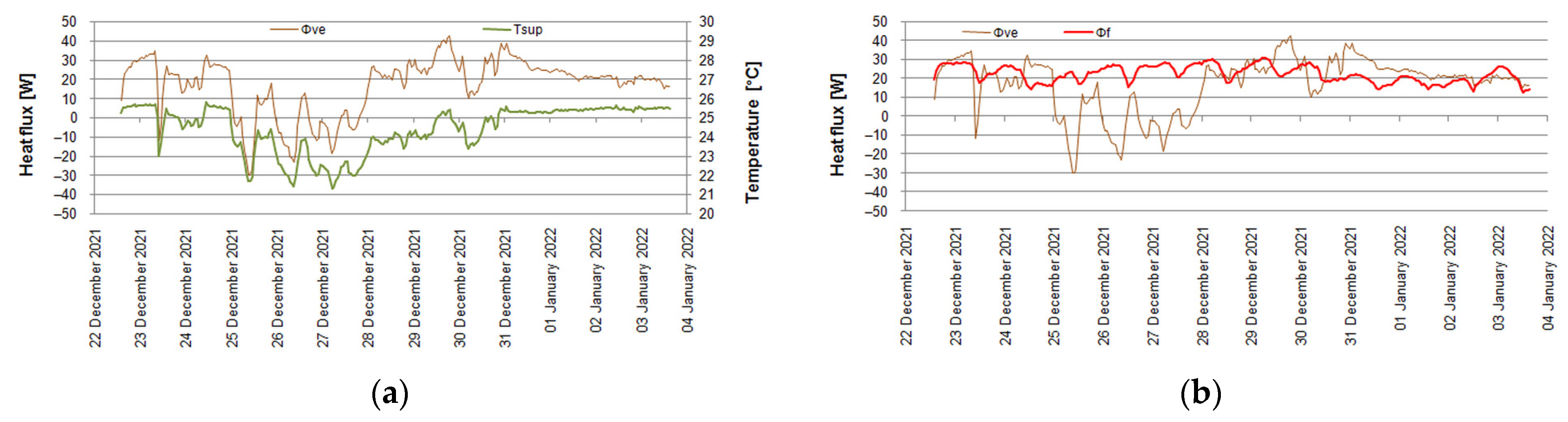
3.1. Measurements

The measurement campaign was conducted from 22 December 2021 to 3 January 2022 during the Christmas break when there were no occupants in the room. Hence, the troublesome estimation of internal gains was neglected. However, the building’s HVAC systems were operating normally due to the presence of international students.
During the studied period, outdoor conditions varied significantly (Figure 4a). The external air temperature ranged from −11.1 °C (at 8:00 on 26 December) to 13.2 °C (at 12:00 on 2 January). The global solar irradiance (Figure 4 b) incident on the external surface of the considered wall ranged from 0 to 223.3 W/m2 (at 12:00 on 26 December).
Indoor air temperature, measured at four heights along the main door-window axis of the room showed high uniformity (Figure 5a). The highest and the lowest values were noticed for the Ti3 sensor placed in the centre of the room and for the Ti4 sensor located about 1.5 m from the window, respectively. Ti4 ranged from 22.1 °C to 24.5 °C while Ti3 ranged from 22.4 °C to 24.8 °C. The hourly difference between these two varied from 0.2 °C to 0.5 °C so it is of the same order as temperature measurement uncertainty (about 0.5 °C) and can be treated as negligible. The ventilation air temperature varied more significantly, from 21.3 °C (5:00 on 27 December) to 25.8 °C (11:00 on 24 December). Comparing Figure 4a with Figure 5a it can be noticed that Tsup was influenced by outdoor conditions (Te). However, during the whole analysed period, Tsup was within the range between 21 °C and 26 °C acceptable for indoor comfort requirements.
The second important investigated group of parameters included temperatures of internal surfaces of the floor (Tf1 and Tf2), internal wall (Tw1), and external wall (Tw2). In addition, the mean radiant temperatures of all internal surfaces facing the tested room measured by the globe thermometer, Tmr, were also considered [78,79,80].
The difference between Tf1 and Tf2 was up to 0.2 °C while the difference between the temperature of the internal wall (Tw1) and the averaged floor temperature was up to 0.7 °C. In both cases, these discrepancies may be treated as negligible. However, larger differences were noted in the case of the temperature of the internal surface of the external wall (Tw2). Due to heat loss to ambient air, it varied from 21.2 °C (22:00 on 27 December) to 23.9 °C (14:00 on 3 January), and in relation to the floor, the temperature was lower by up to 1.8 °C. This was the main reason why the mean radiant temperature (Tmr) was higher than Tw2 and lower than Tf and Tw1. Unfortunately, due to the lack of temperatures of other internal surfaces, radiant temperature calculated using relevant view factors could not be obtained for comparison [81].
In the present study, due to the main focus on the ventilation air system and due to the practical problems with accurate measurement of heating power, the convective hydronic radiator was turned off during the experiment. In the studied object, this can be justified by the relatively small area of the tested room in relation to the entire facility and the good insulation of its envelope, limiting heat loss to the environment. However, in a real building, it is impossible to completely limit the heat exchange with neighbouring rooms as in the adiabatic system. In multi-family buildings, when a radiator in a given flat is lowered or is out of service, this has an impact on the average indoor temperature of the whole building [82]. Therefore, the measurement of the heat flux density flowing through the floor of the room was carried out. This partition was chosen due to the natural tendency of heat to flow upwards as a result of heat gains on the lower storeys and lower thermal resistance for this direction in comparison to other cases [83].
The measured heat flux density varied from 1.0 W/m2 (12:00 on 3 January) to 2.6 W/m2 (6:00 on 29 December), which means heat flux from 12.4 W to 30.9 W. These changes were rather connected with ambient conditions than with heat storage in a floor (or, more generally, in the whole building’s structure) and its transfer between storeys (Figure 6).
Finally, from Equation 9, the heat flux due to ventilation can be calculated (Figure 7). As the variation of Tsup was below 5 °C, it was treated as negligible when considering the resulting air density and specific heat capacity of air and constant ρaca = 1200 J/m3K was assumed. Then, as the indoor air temperature was rather stable, φve followed the changes in Tsup.
Ventilation heat flux ranged from −30 W (10:00 on 25 December) to 42.7 W (19:00 on 29 December) and, except for the period between 25 and 28 December, was of the same order as heat flux through the floor (φf).
There are no installed thermostats in the building and the indoor air temperature in the analysed room was the result of current thermal conditions. In case of unfavourable indoor conditions, occupants may use window opening or roller blinds to prevent overheating or set the thermostatic valve on the radiator.

3.2. Simulations

Values of thermal conductances and single capacitance (Table 2) in the network model of the room were calculated following the procedures given in EN ISO 13790.
The physical properties of materials were obtained from the manufacturers and from PN-EN EN ISO 10456 [84]. Thermal resistances were calculated using the procedure of ISO 6946 [83]. Thermal bridges were neglected. Thermal capacitances were calculated using the detailed method of ISO 13786 [85] for a calculation period of 24 h.
Due to the relatively low variation of the supply air temperature (below 5 °C—see Figure 5a), the volumetric heat capacity of air was assumed to be constant at ρaca = 1200 J/m3K according to EN ISO 13790, as in other studies [65,86,87].
Solar absorptance of the external wall: αsol = 0.9. The total solar energy transmittance of glazing ggl = 0.54 was taken from the technical data of the manufacturer.
Simulations were performed in two cases. They differed by only one element, namely heat flux by the floor. In the first case, it was omitted, but in the second one, it was taken into account as internal heat gain, φint.
Figure 8 presents a comparison of measured and calculated internal air temperature. In the first case, the hourly difference between them varied from 1.1 °C (15:00 on 3 January) to 3.4 °C (22:00 on 27 December). In the second case, this discrepancy was lower and ranged from 0.1 °C (12:00 on 3 January) to 2.3 °C (22:00 on 27 December). Better quality in the second case can be also shown by the aforementioned statistical measures (Table 3).
It also should be mentioned that comparing Figure 8 with Figure 4a, it can be noticed that during the second part of the measurement period, when the outdoor temperature was positive, the difference between simulated and measured indoor air temperature was lower than it was during the remaining time. This may indicate that during the warmer period, the differences between indoor temperatures between neighbouring rooms, which were not measured in this study, were less significant.
Measurement results presented in Figure 6 show that heat flux density through the floor was very small and the inclusion of this quantity into the thermal balance of the room significantly improved the quality of simulation results (Table 3). When multiplying this heat flux by 1.8, i.e., by adding heat flux from 22.3 W to 55.6 W to the base case, the following values of the aforementioned metrics were obtained: MAE = 0.50 °C, RMSE = 0.62 °C, MSE = 0.39 °C2, and R2 = 0.808. An additional heat gain of 50 W, which is lower than in the case of moderate activity of a single person [88], could be sufficient to obtain very good quality modelling results. From this, two conclusions can be drawn. Firstly, internal temperatures in neighbouring rooms should be measured to determine the possibility of heat flow between them, because it may be a significant problem in energy-efficient buildings [89]. Secondly, an additional heater with controlled and measured heating power can be installed in the considered room to easily control thermal stability between rooms.
However, to obtain a more detailed view of the results there should be also made a comparison with other works with thermal measurements and simulations in buildings.
Bagheri et al. [90] simulated a simple single-zone building in thermally heavy and light versions using the TRNSYS program. Outputs from these simulations were used as datasets for the parameter identification in MATLAB of the 4R3C model of a building. In [91], authors used thermal network models of various complexities, namely: 2R1C, 3R1C, 4R3C, 5R3C, 5R4C, and 4R2C for the simulation of two residential test houses. The models were identified in a MATLAB environment using datasets generated by the detailed simulation TRNSYS program. Then, model outputs were compared with TRNSYS results and performed measurements.
Boodi et al. [92] used a parameter identification of a 3R2C model for the simulation of a single room in an educational building. The 3R2C network was used for each external wall, floor, and roof, resulting in the 22R9C model of the studied zone. It was then validated against measurements, but no quantitative indicators were used for this purpose.
In [93], the author used the 5R1C model of EN ISO 13790 to model natural stack ventilation in a residential building. Then, a comparison with the annual hourly simulation in EnergyPlus was made for hourly ventilation flow. In [43], the model was expanded for the simulation of indoor air temperature in a test cell with a double skin façade. The authors also presented a review of various experimental studies of real buildings and test cells in free-running conditions showing that the mean and maximum typical errors of internal air temperature were from 0.3 °C to 2.9 °C and from 1.8 °C to 21.9 °C, respectively.
In [94], this model was modified to the 4R1C version to better describe varying ventilation flow. Simulations in EnergyPlus for 10 different locations were performed for comparison.
Wang et al. [95] used the 3R2C model to simulate the thermal behaviour of a single-family one-story test home. Measurements were used for the identification of the model parameters and then also for 24 h indoor temperature prediction.
Danza et al. [96] used the 3R2C network for each element of a building’s envelope. The model was validated against measurements in a test cell showing an average underestimation of an internal air temperature of −0.08 K.
Vivian et al. [97] presented an evaluation of the 5R1C and 7R2C models to compute the thermal needs of buildings in relation to TRNSYS simulations. Detailed analysis of errors for heating needs and peak load estimation was presented but no further considerations on internal air temperature were given.
Barone et al. [98] developed in MATLAB a simulation tool DETECt based on the thermal resistance-capacitance network approach. They performed an extensive validation procedure using BESTEST tests and measurements taken in a test room located in an educational building. The Mean Absolute Error for indoor air temperature from February to October was 0.39 °C.
Numerous studies devoted to the application of resistance-capacitance models for the thermal modelling of buildings focused only on thermal load analyses, not providing any data on indoor air prediction accuracy [60,66,99]. Only several considered the indoor air temperature (Table 4).
The presented review reveals that there is no study focusing on the simulation of a single, selected room or zone in a more complex, multifamily, building. For this purpose, more detailed simulation tools are used such as EnergyPlus, TRNSYS, ESP-r, or others. Only Shen et al. [58] proposed a modification of a generic 5R1C scheme with zone thermal coupling. They performed an extensive validation of the model against detailed EnergyPlus simulations. The presented values of errors for heating and cooling loads predictions confirmed the good accuracy of the proposed solution. However, the authors did not show such an analysis with regard to internal air temperature. In addition, as the temperature of neighbouring zone is required, this model could not be used in the present study.
An interesting addition to the presented research is the study by Zhang et al. [100] in which authors compared CFD simulation with measurements performed in a test chamber to assess the effect of selected parameters on indoor air quality, indoor comfort, and energy efficiency of stratum ventilation used for space heating. The authors suggested setting maximum ventilation flow and modulation of supply air temperature following the outdoor weather condition.

4. Conclusions

This paper presents the application of a simple thermal network model of a building zone to simulate indoor air temperature in a single room of a multi-storey building with a mechanical ventilation system with heat recovery. Ventilation air was supposed to be the only heat source and its ability to maintain the required indoor air temperature was checked in simulations and then compared with measurements. The performed measurements showed the practical applicability of the analysed ventilation system to provide space heating while maintaining indoor air temperature within the required range under studied outdoor conditions.
For simulations, the simple but well-known 5R1C thermal network model of a building zone from EN ISO 13790 was used. Comparison with measurements showed the Mean Absolute Error (MAE) and Root Mean Square Error (RMSE) of the calculated indoor air temperature to be 2.37 °C and 2.45 °C, respectively.
As these values were not satisfying, further analysis was performed. When including heat gains from the bottom storey, a significant improvement in the quality of prediction was obtained with MAE = 1.28 °C and RMSE = 1.38 °C. Further introduction of artificial heat flux with a value of 80% resulted in MAE = 0.50 °C and RMSE = 0.62 °C. Hence, in future measurements, it can be checked whether the quality of the model will be better during normal use of the room when internal gains for occupants can be added.
It also would be advisable to measure the temperature of internal surfaces facing the considered room in terms of indoor comfort and the impact of solar irradiance. The indoor temperature in surrounding rooms should also be known to determine the possibility of heat transfer direction between them and the analysed space. The simulation model can be also extended to include additional couplings with neighbouring zones.

Funding

This research received no external funding.

Conflicts of Interest

The author declares no conflict of interest.

Symbols

Aftotal conditioned (heated and/or cooled) floor area, m2
Ameffective thermal mass area, m2
Cmthermal capacity of the building, J/K
Htr,emexternal part of the Htr,op thermal transmission coefficient, W/K
Htr,iscoupling conductance, W/K
Htr,msinternal part of the Htr,op thermal transmission coefficient, W/K
Htr,opthermal transmission coefficient for thermally heavy envelope elements, W/K
Htr,wthermal transmission coefficient for thermally light envelope elements, W/K
Hvethermal transmission coefficient by ventilation air, W/K
Teexternal (outdoor) air temperature, °C
Te;mn;anmean annual temperature of outdoor air, °C
Te;max;mmaximum mean monthly temperature of outdoor air, °C
Tiinternal (indoor) air temperature, °C
Ti,C,setset-point indoor air temperature for cooling, °C
Ti,H,setset-point indoor air temperature for heating, °C
Tmaverage air temperature in the duct, °C
Tscentral node temperature, °C
Tsupsupply air temperature, °C
caspecific heat capacity of air, J/(kg∙K)
ρaair density, kg/m3
φiaheat flow rate to internal air node, W
φintheat flow rate due to internal heat sources, W
φmheat flow rate to mass node, W
φsolheat flow rate due to solar heat sources, W
φstheat flow rate to central node, W
φveheat flow rate by ventilation, W
φHCheating or cooling power supplied to or extracted from the indoor air node, W

References

  1. Jędrzejuk, H.; Dybińnski, O. The influence of a heating system control program and thermal mass of external walls on the internal comfort in the Polish climate. Energy Procedia 2015, 78, 1087–1092. [Google Scholar] [CrossRef] [Green Version]
  2. Chodkowska-Miszczuk, J.; Szymanska, D. Modernisation of public buildings in Polish towns and the concept of sustainable building. Quaest. Geogr. 2014, 33, 89–99. [Google Scholar] [CrossRef] [Green Version]
  3. Nowak-Dzieszko, K.; Rojewska-Warchał, M. Thermal comfort of the individual flats of multi–family panel building. Tech. Trans. Civil. Eng. 2014, 5-B/2014, 201–206. [Google Scholar] [CrossRef]
  4. Sadowska, B. Effects of deep thermal modernization and use of renewable energy in public buildings in north-eastern Poland. In Proceedings of the 20th International Scientific Conference Engineering for Rural Development, Jelgava, Latvia, 26–28 May 2018; Malinovska, L., Osadcuks, V., Eds.; Latvia University of Life Sciences and Technologies: Jelgava, Latvia, 2018; pp. 1870–1875. [Google Scholar] [CrossRef]
  5. Michalak, P.; Szczotka, K.; Szymiczek, J. Energy Effectiveness or Economic Profitability? A Case Study of Thermal Modernization of a School Building. Energies 2021, 14, 1973. [Google Scholar] [CrossRef]
  6. Ratajczak, K.; Michalak, K.; Narojczyk, M.; Amanowicz, Ł. Real Domestic Hot Water Consumption in Residential Buildings and Its Impact on Buildings’ Energy Performance—Case Study in Poland. Energies 2021, 14, 5010. [Google Scholar] [CrossRef]
  7. Amanowicz, Ł.; Ratajczak, K.; Dudkiewicz, E. Recent Advancements in Ventilation Systems Used to Decrease Energy Consumption in Buildings—Literature Review. Energies 2023, 16, 1853. [Google Scholar] [CrossRef]
  8. Xu, Q.; Riffat, S.; Zhang, S. Review of Heat Recovery Technologies for Building Applications. Energies 2019, 12, 1285. [Google Scholar] [CrossRef] [Green Version]
  9. Zender–Świercz, E. A Review of Heat Recovery in Ventilation. Energies 2021, 14, 1759. [Google Scholar] [CrossRef]
  10. Attia, S.; Kosiński, P.; Wójcik, R.; Węglarz, A.; Koc, D.; Laurent, O. Energy efficiency in the Polish residential building stock: A literature review. J. Build. Eng. 2022, 45, 103461. [Google Scholar] [CrossRef]
  11. Firląg, S. Cost-Optimal Plus Energy Building in a Cold Climate. Energies 2019, 12, 3841. [Google Scholar] [CrossRef] [Green Version]
  12. Sowa, J.; Mijakowski, M. Humidity-Sensitive, Demand-Controlled Ventilation Applied to Multiunit Residential Building—Performance and Energy Consumption in Dfb Continental Climate. Energies 2020, 13, 6669. [Google Scholar] [CrossRef]
  13. Borowski, M. Hotel Adapted to the Requirements of an nZEB Building—Thermal Energy Performance and Assessment of Energy Retrofit Plan. Energies 2022, 15, 6332. [Google Scholar] [CrossRef]
  14. Zukowski, M. A Small Modular House as a Response to the Energy Crisis. Energies 2022, 15, 8058. [Google Scholar] [CrossRef]
  15. EN 12831; Heating Systems in Buildings—Method for Calculation of the Design Heat Load. International Organization for Standardization (ISO): Geneva, Switzerland, 2017.
  16. Barwińska Małajowicz, A.; Knapková, M.; Szczotka, K.; Martinkovičová, M.; Pyrek, R. Energy Efficiency Policies in Poland and Slovakia in the Context of Individual Well-Being. Energies 2023, 16, 116. [Google Scholar] [CrossRef]
  17. Rotar, N.; Badescu, V. Considerations on the implementation of the Passive House concept in South-Eastern Europe (Romania). Int. J. Green Energy 2011, 8, 780–794. [Google Scholar] [CrossRef]
  18. Dall’O’, G.; Sarto, L. Potential and limits to improve energy efficiency in space heating in existing school buildings in northern Italy. Energy Build. 2013, 67, 298–308. [Google Scholar] [CrossRef]
  19. Szul, T. Assessment of the accuracy of the approximate method used to estimate the heating power demand for single-family houses. J. Res. Appl. Agric. Eng. 2018, 63, 126–129. [Google Scholar]
  20. Szymiczek, J.; Szczotka, K.; Banaś, M.; Jura, P. Efficiency of a Compressor Heat Pump System in Different Cycle Designs: A Simulation Study for Low-Enthalpy Geothermal Resources. Energies 2022, 15, 5546. [Google Scholar] [CrossRef]
  21. PLoSkić, A.; Holmberg, S. Low-temperature ventilation pre-heater in combination with conventional room heaters. Energy Build. 2013, 65, 248–259. [Google Scholar] [CrossRef]
  22. Šimko, M.; Krajčík, M.; Šikula, O.; Šimko, P.; Kalús, D. Insulation panels for active control of heat transfer in walls operated as space heating or as a thermal barrier: Numerical simulations and experiments. Energy Build. 2018, 158, 135–146. [Google Scholar] [CrossRef]
  23. Krajčík, M.; Šimko, M.; Šikula, O.; Szabó, D.; Petráš, D. Thermal performance of a radiant wall heating and cooling system with pipes attached to thermally insulating bricks. Energy Build. 2021, 246, 111122. [Google Scholar] [CrossRef]
  24. Krajčík, M.; Arıcı, M.; Šikula, O.; Šimko, M. Review of water-based wall systems: Heating, cooling, and thermal barriers. Energy Build. 2021, 253, 111476. [Google Scholar] [CrossRef]
  25. Harsem, T.T.; Nourozi, B.; Behzadi, A.; Sadrizadeh, S. Design and Parametric Investigation of an Efficient Heating System, an Effort to Obtain a Higher Seasonal Performance Factor. Energies 2021, 14, 8475. [Google Scholar] [CrossRef]
  26. Javed, S.; Ørnes, I.R.; Dokka, T.H.; Myrup, M.; Holøs, S.B. Evaluating the Use of Displacement Ventilation for Providing Space Heating in Unoccupied Periods Using Laboratory Experiments, Field Tests and Numerical Simulations. Energies 2021, 14, 952. [Google Scholar] [CrossRef]
  27. Mao, Y.; Xie, H.; Zhang, X.; Hou, F.; Wang, M. Study on the Applicable Room Size Dimension of Stratum Ventilation for Heating Based on Multi-Criteria Analytic Hierarchy Process-Entropy Weight Model. Buildings 2023, 13, 381. [Google Scholar] [CrossRef]
  28. Ameen, A.; Choonya, G.; Cehlin, M. Experimental Evaluation of the Ventilation Effectiveness of Corner Stratum Ventilation in an Office Environment. Buildings 2019, 9, 169. [Google Scholar] [CrossRef] [Green Version]
  29. Ameen, A.; Cehlin, M.; Larsson, U.; Karimipanah, T. Experimental investigation of ventilation performance of different air distribution systems in an office environment—Cooling mode. Energies 2019, 12, 1354. [Google Scholar] [CrossRef] [Green Version]
  30. Ameen, A.; Cehlin, M.; Larsson, U.; Karimipanah, T. Experimental Investigation of Ventilation Performance of Different Air Distribution Systems in an Office Environment—Heating Mode. Energies 2019, 12, 1835. [Google Scholar] [CrossRef] [Green Version]
  31. Kong, X.; Xi, C.; Li, H.; Lin, Z. A comparative experimental study on the performance of mixing ventilation and stratum ventilation for space heating. Build. Environ. 2019, 157, 34–46. [Google Scholar] [CrossRef]
  32. Kowalski, P.; Szałański, P.; Cepiński, W. Waste Heat Recovery by Air-to-Water Heat Pump from Exhausted Ventilating Air for Heating of Multi-Family Residential Buildings. Energies 2021, 14, 7985. [Google Scholar] [CrossRef]
  33. Lin, Y.; Zhao, L.; Yang, W.; Hao, X.; Li, C.-Q. A review on research and development of passive building in China. J. Build. Eng. 2021, 42, 102509. [Google Scholar] [CrossRef]
  34. Diaz de Garayo, S.; Martínez, A.; Astrain, D. Optimal combination of an air-to-air thermoelectric heat pump with a heat recovery system to HVAC a passive house dwelling. Appl. Energy 2022, 309, 118443. [Google Scholar] [CrossRef]
  35. Kang, Y.; Ma, N.; Bunster, V.; Chang, V.W.-C.; Zhou, J. Optimizing the Passive House Planning Package simulation tool: A bottom-up dynamic approach to reduce building performance gap. Energy Build. 2022, 276, 112512. [Google Scholar] [CrossRef]
  36. Zaniboni, L.; Albatici, R. Natural and Mechanical Ventilation Concepts for Indoor Comfort and Well-Being with a Sustainable Design Perspective: A Systematic Review. Buildings 2022, 12, 1983. [Google Scholar] [CrossRef]
  37. La Fleur, L.; Moshfegh, B.; Rohdin, P. Measured and predicted energy use and indoor climate before and after a major renovation of an apartment building in Sweden. Energy Build. 2017, 146, 98–110. [Google Scholar] [CrossRef] [Green Version]
  38. La Fleur, L.; Rohdin, P.; Moshfegh, B. Energy Use and Perceived Indoor Environment in a Swedish Multifamily Building before and after Major Renovation. Sustainability 2018, 10, 766. [Google Scholar] [CrossRef] [Green Version]
  39. Liu, L.; Rohdin, P.; Moshfegh, B. Evaluating indoor environment of a retrofitted multi-family building with improved energy performance in Sweden. Energy Build. 2015, 102, 32–44. [Google Scholar] [CrossRef]
  40. Markiewicz-Zahorski, P.; Rucińska, J.; Fedorczak-Cisak, M.; Zielina, M. Building Energy Performance Analysis after Changing Its Form of Use from an Office to a Residential Building. Energies 2021, 14, 564. [Google Scholar] [CrossRef]
  41. Veršić, Z.; Binički, M.; Nosil Mešić, M. Passive Night Cooling Potential in Office Buildings in Continental and Mediterranean Climate Zone in Croatia. Buildings 2022, 12, 1207. [Google Scholar] [CrossRef]
  42. EN-ISO 52016-1:2017; Energy Performance of Buildings—Energy Needs for Heating and Cooling, Internal Temperatures and Sensible and Latent Heat Loads—Part 1: Calculation Procedures. ISO: Geneva, Switzerland, 2017.
  43. Oliveira Panão, M.J.N.; Santos, C.A.P.; Mateus, N.M.; Carrilho Da Graça, G. Validation of a lumped RC model for thermal simulation of a double skin natural and mechanical ventilated test cell. Energy Build. 2016, 121, 92–103. [Google Scholar] [CrossRef]
  44. EN ISO 13790; Energy Performance of Buildings—Calculation of Energy Use for Space Heating and Cooling. ISO: Geneva, Switzerland, 2008.
  45. Lundström, L.; Akander, J.; Zambrano, J. Development of a Space Heating Model Suitable for the Automated Model Generation of Existing Multifamily Buildings—A Case Study in Nordic Climate. Energies 2019, 12, 485. [Google Scholar] [CrossRef] [Green Version]
  46. Zakula, T.; Bagaric, M.; Ferdelji, N.; Milovanovic, B.; Mudrinic, S.; Ritosa, K. Comparison of dynamic simulations and the ISO 52016 standard for the assessment of building energy performance. Appl. Energy 2019, 254, 113553. [Google Scholar] [CrossRef]
  47. Ballarini, I.; Costantino, A.; Fabrizio, E.; Corrado, V. A Methodology to Investigate the Deviations between Simple and Detailed Dynamic Methods for the Building Energy Performance Assessment. Energies 2020, 13, 6217. [Google Scholar] [CrossRef]
  48. Gumbarević, S.; Burcar Dunović, I.; Milovanović, B.; Gaši, M. Method for Building Information Modeling Supported Project Control of Nearly Zero-Energy Building Delivery. Energies 2020, 13, 5519. [Google Scholar] [CrossRef]
  49. Du, L.; Yang, L.; Yang, C.; Hu, C.; Yu, C.; Qiu, M.; Liu, S.; Zhu, S.; Ye, X. Development and Validation of an Energy Consumption Model for Animal Houses Achieving Precision Livestock Farming. Animals 2022, 12, 2580. [Google Scholar] [CrossRef]
  50. Patrčević, F.; Dović, D.; Horvat, I.; Filipović, P. A Novel Dynamic Approach to Cost-Optimal Energy Performance Calculations of a Solar Hot Water System in an nZEB Multi-Apartment Building. Energies 2022, 15, 509. [Google Scholar] [CrossRef]
  51. Horvat, I.; Dović, D. Dynamic modeling approach for determining buildings technical system energy performance. Energy Convers. Manag. 2016, 125, 154–165. [Google Scholar] [CrossRef]
  52. Heidarinejad, M.; Mattise, N.; Dahlhausen, M.; Sharma, K.; Benne, K.; Macumber, D.; Brackney, L.; Srebric, J. Demonstration of reduced-order urban scale building energy models. Energy Build. 2017, 156, 17–28. [Google Scholar] [CrossRef]
  53. Elci, M.; Delgado, B.M.; Henning, H.M.; Henze, G.P.; Herkel, S. Aggregation of residential buildings for thermal building simulations on an urban district scale. Sustain. Cities Soc. 2018, 39, 537–547. [Google Scholar] [CrossRef]
  54. Tagliabue, L.C.; Buzzetti, M.; Marenzi, G. Energy performance of greenhouse for energy saving in buildings. Energy Procedia 2012, 30, 1233–1242. [Google Scholar] [CrossRef] [Green Version]
  55. Fabrizio, E.; Ghiggini, A.; Bariani, M. Energy performance and indoor environmental control of animal houses: A modelling tool. Energy Procedia 2015, 82, 439–444. [Google Scholar] [CrossRef] [Green Version]
  56. Jayathissa, P.; Luzzatto, M.; Schmidli, J.; Hofer, J.; Nagy, Z.; Schlueter, A. Optimising building net energy demand with dynamic BIPV shading. Appl. Energy 2017, 202, 726–735. [Google Scholar] [CrossRef]
  57. Klein, K.; Herkel, S.; Henning, H.-M.; Felsmann, C. Load shifting using the heating and cooling system of an office building: Quantitative potential evaluation for different flexibility and storage options. Appl. Energy 2017, 203, 917–937. [Google Scholar] [CrossRef]
  58. Shen, P.; Braham, W.; Yi, Y. Development of a lightweight building simulation tool using simplified zone thermal coupling for fast parametric study. Appl. Energy 2018, 223, 188–214. [Google Scholar] [CrossRef]
  59. Michalak, P. Hourly Simulation of an Earth-to-Air Heat Exchanger in a Low-Energy Residential Building. Energies 2022, 15, 1898. [Google Scholar] [CrossRef]
  60. Fischer, D.; Wolf, T.; Scherer, J.; Wille-Haussmann, B. A stochastic bottom-up model for space heating and domestic hot water load profiles for German households. Energy Build. 2016, 124, 120–128. [Google Scholar] [CrossRef]
  61. Costantino, A.; Fabrizio, E.; Ghiggini, A.; Bariani, M. Climate control in broiler houses: A thermal model for the calculation of the energy use and indoor environmental conditions. Energy Build. 2018, 169, 110–126. [Google Scholar] [CrossRef]
  62. Hedegaard, R.E.; Kristensen, M.H.; Pedersen, T.H.; Brun, A.; Petersen, S. Bottom-up modelling methodology for urban-scale analysis of residential space heating demand response. Appl. Energy 2019, 242, 181–204. [Google Scholar] [CrossRef]
  63. Costantino, A.; Comba, L.; Sicardi, G.; Bariani, M.; Fabrizio, E. Energy performance and climate control in mechanically ventilated greenhouses: A dynamic modelling-based assessment and investigation. Appl. Energy 2021, 288, 116583. [Google Scholar] [CrossRef]
  64. Buonomano, A.; Forzano, C.; Kalogirou, S.A.; Palombo, A. Building-façade integrated solar thermal collectors: Energy-economic performance and indoor comfort simulation model of a water based prototype for heating, cooling, and DHW production. Renew. Energy 2019, 137, 20–36. [Google Scholar] [CrossRef]
  65. Dalla Mora, T.; Teso, L.; Carnieletto, L.; Zarrella, A.; Romagnoni, P. Comparative Analysis between Dynamic and Quasi-Steady-State Methods at an Urban Scale on a Social-Housing District in Venice. Energies 2021, 14, 5164. [Google Scholar] [CrossRef]
  66. Bruno, R.; Pizzuti, G.; Arcuri, N. The Prediction of Thermal Loads in Building by Means of the EN ISO 13790 Dynamic Model: A Comparison with TRNSYS. Energy Procedia 2016, 101, 192–199. [Google Scholar] [CrossRef]
  67. Michalak, P. Thermal–electrical analogy in dynamic simulations of buildings: Comparison of four numerical solution methods. J. Mech. Energy Eng. 2020, 4, 179–188. [Google Scholar] [CrossRef]
  68. Michalak, P. Ventilation heat loss in a multifamily building under varying air density. J. Mech. Energy Eng. 2020, 4, 97–102. [Google Scholar] [CrossRef]
  69. Michalak, P. Impact of Air Density Variation on a Simulated Earth-to-Air Heat Exchanger’s Performance. Energies 2022, 15, 3215. [Google Scholar] [CrossRef]
  70. Digital Plug & Play Infrared Thermometer in a TO-Can. MLX90614. Available online: https://www.melexis.com/en/product/mlx90614/digital-plug-play-infrared-thermometer-to-can (accessed on 20 February 2023).
  71. Mobaraki, B.; Komarizadehasl, S.; Castilla Pascual, F.J.; Lozano-Galant, J.A.; Porras Soriano, R. A Novel Data Acquisition System for Obtaining Thermal Parameters of Building Envelopes. Buildings 2022, 12, 670. [Google Scholar] [CrossRef]
  72. Zhang, K.; Wang, X. High-Precision Measurement of Sea Surface Temperature with Integrated Infrared Thermometer. Sensors 2022, 22, 1872. [Google Scholar] [CrossRef]
  73. Adeala, A.A.; Huan, Z.; Enweremadu, C.C. Evaluation of global solar radiation using multiple weather parameters as predictors for South Africa Provinces. Therm. Sci. 2015, 19, 495–509. [Google Scholar] [CrossRef]
  74. Pham, H. A New Criterion for Model Selection. Mathematics 2019, 7, 1215. [Google Scholar] [CrossRef] [Green Version]
  75. Kadad, I.M.; Ramadan, A.A.; Kandil, K.M.; Ghoneim, A.A. Relationship between Ultraviolet-B Radiation and Broadband Solar Radiation under All Sky Conditions in Kuwait Hot Climate. Energies 2022, 15, 3130. [Google Scholar] [CrossRef]
  76. Salah, S.; Alsamamra, H.R.; Shoqeir, J.H. Exploring Wind Speed for Energy Considerations in Eastern Jerusalem-Palestine Using Machine-Learning Algorithms. Energies 2022, 15, 2602. [Google Scholar] [CrossRef]
  77. Varga, Z.; Racz, E. Machine Learning Analysis on the Performance of Dye-Sensitized Solar Cell—Thermoelectric Generator Hybrid System. Energies 2022, 15, 7222. [Google Scholar] [CrossRef]
  78. Delaforce, S.R.; Hitchin, E.R.; Watson, D.M.T. Convective heat transfer at internal surfaces. Build. Environ. 1993, 28, 211–220. [Google Scholar] [CrossRef]
  79. Sukamto, D.; Siroux, M.; Gloriant, F. Hot Box Investigations of a Ventilated Bioclimatic Wall for NZEB Building Façade. Energies 2021, 14, 1327. [Google Scholar] [CrossRef]
  80. Shinoda, J.; Kazanci, O.B.; Tanabe, S.; Olesen, B.W. A review of the surface heat transfer coefficients of radiant heating and cooling systems. Build. Environ. 2019, 159, 106156. [Google Scholar] [CrossRef]
  81. Do, H.Q.; Luther, M.B.; Amirkhani, M.; Wang, Z.; Martek, I. Radiant Conditioning Retrofitting for Residential Buildings. Energies 2022, 15, 449. [Google Scholar] [CrossRef]
  82. Hayati, A.; Akander, J.; Eriksson, M. A Case Study of Mapping the Heating Storage Capacity in a Multifamily Building within a District Heating Network in Mid-Sweden. Buildings 2022, 12, 1007. [Google Scholar] [CrossRef]
  83. ISO 6946:2017; Building Components and Building Elements—Thermal Resistance and Thermal Transmittance—Calculation Methods. International Organization for Standardization: Geneva, Switzerland, 2017.
  84. EN ISO 10456; Building Materials and Products—Hygrothermal Properties—Tabulated Design Values and Procedures for Determining Declared and Design Thermal Values. International Organization for Standardization: Geneva, Switzerland, 2007.
  85. ISO 13786:2017; Thermal Performance of Building Components—Dynamic Thermal Characteristics—Calculation Methods. ISO: Geneva, Switzerland, 2017.
  86. Lomas, K.J. Architectural design of an advanced naturally ventilated building form. Energy Build. 2007, 39, 166–181. [Google Scholar] [CrossRef]
  87. Skotnicka-Siepsiak, A. An Evaluation of the Performance of a Ground-to-Air Heat Exchanger in Different Ventilation Scenarios in a Single-Family Home in a Climate Characterized by Cold Winters and Hot Summers. Energies 2022, 15, 105. [Google Scholar] [CrossRef]
  88. Hong, S.H.; Lee, J.M.; Moon, J.W.; Lee, K.H. Thermal Comfort, Energy and Cost Impacts of PMV Control Considering Individual Metabolic Rate Variations in Residential Building. Energies 2018, 11, 1767. [Google Scholar] [CrossRef] [Green Version]
  89. Cholewa, T.; Siggelsten, S.; Balen, I.; Ficco, G. Heat cost allocation in buildings: Possibilities, problems and solutions. J. Build. Eng. 2020, 31, 101349. [Google Scholar] [CrossRef]
  90. Bagheri, A.; Genikomsakis, K.N.; Feldheim, V.; Ioakimidis, C.S. Sensitivity Analysis of 4R3C Model Parameters with Respect to Structure and Geometric Characteristics of Buildings. Energies 2021, 14, 657. [Google Scholar] [CrossRef]
  91. Bagheri, A.; Genikomsakis, K.N.; Ioakimidis, C.S. Implementation of System Identification Techniques and Optimal Control for RC Model Selection by Means of TRNSYS Simulation Results and Experimental Data. Buildings 2022, 12, 1625. [Google Scholar] [CrossRef]
  92. Boodi, A.; Beddiar, K.; Amirat, Y.; Benbouzid, M. Simplified Building Thermal Model Development and Parameters Evaluation Using a Stochastic Approach. Energies 2020, 13, 2899. [Google Scholar] [CrossRef]
  93. Michalak, P. Thermal—Airflow Coupling in Hourly Energy Simulation of a Building with Natural Stack Ventilation. Energies 2022, 15, 4175. [Google Scholar] [CrossRef]
  94. Michalak, P. A thermal-network model for the dynamic simulation of the energy performance of buildings with the time varying ventilation flow. Energy Build. 2019, 202, 109337. [Google Scholar] [CrossRef]
  95. Wang, J.; Jiang, Y.; Tang, C.Y.; Song, L. Development and validation of a second-order thermal network model for residential buildings. Appl. Energy 2022, 306, 118124. [Google Scholar] [CrossRef]
  96. Danza, L.; Belussi, L.; Meroni, I.; Salamone, F.; Floreani, F.; Piccinini, A.; Dabusti, A. A Simplified Thermal Model to Control the Energy Fluxes and to Improve the Performance of Buildings. Energy Procedia 2016, 101, 97–104. [Google Scholar] [CrossRef]
  97. Vivian, J.; Zarrella, A.; Emmi, G.; De Carli, M. An evaluation of the suitability of lumped-capacitance models in calculating energy needs and thermal behaviour of buildings. Energy Build. 2017, 150, 447–465. [Google Scholar] [CrossRef]
  98. Barone, G.; Buonomano, A.; Forzano, C.; Palombo, A. Building Energy Performance Analysis: An Experimental Validation of an In-House Dynamic Simulation Tool through a Real Test Room. Energies 2019, 12, 4107. [Google Scholar] [CrossRef] [Green Version]
  99. Ding, Y.; Lyu, Y.; Lu, S.; Wang, R. Load shifting potential assessment of building thermal storage performance for building design. Energy 2022, 243, 123036. [Google Scholar] [CrossRef]
  100. Zhang, S.; Lin, Z.; Ai, Z.; Wang, F.; Cheng, Y.; Huang, C. Effects of operation parameters on performances of stratum ventilation for heating mode. Build. Environ. 2019, 148, 55–66. [Google Scholar] [CrossRef]
Figure 1. The 5R1C thermal network model of a building zone from EN ISO 13790.
Energies 16 03456 g001
Figure 2. The test room: (a) View of the room selected for experiment; (b) Schematic location of sensors in the room.
Energies 16 03456 g002
Figure 3. (a) View of the measurement equipment during assembling; (b) Measurement of ventilation airflow rate with Testo 417 anemometer.
Energies 16 03456 g003
Figure 4. Meteorological conditions during the experiment: (a) External air temperature; (b) Global solar irradiance on the external wall.
Energies 16 03456 g004
Figure 5. Measurement results: (a) Indoor and supplying air temperature; (b) Mean radiant, floor, and internal wall temperature.
Energies 16 03456 g005
Figure 6. Measurement results: (a) Floor temperature and floor heat flux density; (b) Outdoor air temperature and floor heat flux density.
Energies 16 03456 g006
Figure 7. Measurement results: (a) Calculated ventilation heat flux and supplying air temperature; (b) Calculated ventilation heat flux and measured floor heat flux.
Energies 16 03456 g007
Figure 8. Measured and simulated indoor air temperature: (a) Case 1; (b) Case 2.
Energies 16 03456 g008
Table 1. The main metrological parameters of the measuring sensors used.
SensorMeasured VariableMeasurement RangeAccuracy
Pt100/Pt1000 platinum resistance sensorAir and floor temperature−50 °C ÷ +150 °CClass A (1)
TP875.1 with the Pt100 sensorRadiant temperature−30 °C ÷ +120 °C±0.2 °C
CMP11 Kipp&ZonenGlobal solar irradiance0 ÷ 4000 W/m2Spectrally Flat Class A (2)
HFP01 HuksefluxHeat flux−2000 ÷ 2000 W/m2±3%
Testo 417Airflow rate0 ÷ 200 m3/h±0.1 m3/h (3)
(1) According to EN 60751; (2) According to ISO 9060; (3) Resolution for 0 ÷ 99.9 m3/h range.
Table 2. Thermal network model elements of the building.
ElementValueUnit
Htr,w2.61W/K
Htr,is193.48W/K
Htr,ms264.32W/K
Htr,em0.84W/K
Hve16.67W/K
Cm2.63MJ/K
Table 3. Statistical indicators for indoor air simulation obtained for both cases.
ElementCase 1Case 2
MAE2.371.28
RMSE2.451.38
MSE5.981.91
R20.710.77
Table 4. Simulations of buildings with the use of thermal network models with error analyses of indoor air temperature.
ReferenceObjectModelSimulationMeasurementMAERMSEMSER2
[91]9 zones2R1CTRNSYSNn.a.6.55 °C42.51 °C2n.a.
[91]9 zones3R1CTRNSYSNn.a.8.49 °C17.71 °C2n.a.
[91]9 zones4R3CTRNSYSNn.a.1.06 °C0.76 °C2n.a.
[91]9 zones5R3CTRNSYSNn.a.5.02 °C3.37 °C2n.a.
[91]9 zones5R4CTRNSYSNn.a.0.70 °C0.81 °C2n.a.
[91]9 zones4R2CTRNSYSNn.a.3.08 °C6.72 °C2n.a.
[43]1 zone5R1C-Y0.95–1.13 °Cn.a.n.a.n.a.
[94]1 zone4R1CEnergyPlusN0.30–0.48 °C0.61–0.93 °C0.37–0.86 °C20.84–0.93
[95]1 zone3R2C-Y0.34–0.5 °C0.42–0.65 °Cn.a.n.a.
Disclaimer/Publisher’s Note: The statements, opinions and data contained in all publications are solely those of the individual author(s) and contributor(s) and not of MDPI and/or the editor(s). MDPI and/or the editor(s) disclaim responsibility for any injury to people or property resulting from any ideas, methods, instructions or products referred to in the content.

