1. Background and Technology Selection
The Balance of Plant (BoP) of the European Demonstration Fusion Power Plant (EU DEMO) is foreseen to come into operation in the middle of this century, with the main aim of demonstrating the production of a few hundred MWs of net electricity [
1].
During the EUROfusion Horizon 2020 Programme (2014–2020), preconceptual design of the Water-Cooled Lead–Lithium (WCLL) Breeding Blanket (BB) Primary Heat Transfer System (PHTS) was carried out, as well as preliminary technology selection and design of the Breeding Zone (BZ) and First Wall (FW) steam generators [
2].
Following the outcomes of this preconceptual design phase, in 2021, the authors, after a preliminary investigation, confirmed the technology selection of the Once Through Steam Generators (OTSGs), inspired by Babcock & Wilcox Pressure Water Reactor (B&W PWR) technology [
3,
4] for the WCLL BB DEMO steam generators.
As shown in the simplified scheme in
Figure 1, this type of steam generator is typically a vertically oriented, once-through, up-boiling, cross-counter-flow, shell-and-tube heat exchanger [
4]. In the bundle, there are mainly two sections: a boiler that converts water into steam and a superheater section, which allows this steam generator to deliver superheated steam with quality close to 100% at constant pressure to the turbine throttle. The hot primary coolant enters from the top, flows downward inside the tubes, and exits from the bottom, while the feedwater enters at the midplane through several inlet nozzles around the shell and flows downward in an annular chamber between the shell and the tube bundle shroud. More details on heat transfer regions of this kind of steam generator, as well as correlations applied for the thermal-hydraulic design, are reported in
Section 2.
The main reasons that led the authors to confirm the choice of this technology are, first, that the primary (PHTS itself) and secondary (Power Conversion System, PCS) sides’ water thermodynamic conditions are comparable with respect to those of a PWR, and second, that low water inventory present in this type of steam generator enables its prompt response, particularly suited for the pulsed power regime foreseen during DEMO normal operations. In fact, the DEMO duty cycle foresees a continuous sequence of two main phases (pulse and dwell phases) connected by two transitional phases (pulse-dwell and dwell-pulse transition). In particular, the plasma ramps up within about 100 s, bringing its power from 0 to the nominal value of around 2 GWth. When the full power level is reached, this condition is kept for around 2 h (pulse phase). Then, a ramp-down of about 100 s leads the system into the dwell phase, which lasts 10 min and during which almost no power is generated (the decay heat 1 s after shut-down is around 2% of the nominal power) [
1].
Having confirmed the selection of the technology to be applied for the WCLL BoP and having received the new DEMO energy map by EUROfusion, in 2021, the authors started and then completed the conceptual design of these components, whose design is described in detail in the following sections of this paper. Furthermore, as also reported below, this design activity was performed for the WCLL BoP reference configuration, namely the WCLL BoP Direct Coupling Design with Small Energy Storage (BoP DCD Small ESS) with a “pulsating” PCS operating at low load in dwell [
1,
2].
2. Thermal-Hydraulic Design
Several boundary conditions had to be considered to perform the thermal-hydraulic design of the BB PHTS OTSGs. First, the component sizing power was determined taking into account the latest available DEMO power source data and the current PHTS layout. Referring to the former, several uncertainties still affect the fusion power (estimated to be between 1900 and 2000 MW) and, above all, its distribution among the different DEMO sources (i.e., breeding blanket, divertor, and vacuum vessel). Furthermore, it is worth remembering that the blanket is subdivided into two principal subsystems, namely the breeding zone and the first wall, thermally coupled within the component and each provided with an independent PHTS. The actual repartition of the blanket power between the two cooling circuits is still under evaluation. For this, instead of a single value, the current DEMO power map provides a power range associated with each PHTS. Conservatively, the sizing of the BZ and FW OTSGs was carried out considering the maximum value belonging to the corresponding range. Then, for each circuit, this power term was equally distributed among two identical components, according to the current PHTS configuration. Concerning the OTSG primary and secondary side temperatures, they were imposed by the BB and PCS requirements, respectively. For the latter, the reference cycle was developed during FP8 referring to the WCLL BoP Direct Coupling Design (DCD) with small Energy Storage System (ESS).
Once we clearly set the boundary conditions, the design activity was divided into two steps. Step 1: the steam generator layout was preliminarily evaluated using an analytical procedure. Step 2: a thermal-hydraulic model of the OTSG component was prepared based on the analytically computed geometry and the component thermal-hydraulic behaviour verified by means of numerical calculations. For simulation purposes, the best-estimate system code RELAP5/Mod3.3 was used [
5].
Referring to the analytical procedure, several aspects are worth mentioning. B&W tube layout was also considered for the BB OTSGs. Indeed, their primary and secondary side water conditions (i.e., pressure difference between tube internal and external sections) are like the PWR ones.
As a first guess, the OTSG transversal geometry (i.e., tube number, shell and vessel internal diameter, etc.) was scaled from the B&W design, in particular from the units installed in the Three Mile Island Nuclear Power Plant (TMI NPP). A literature review allowed us to fully characterize this reference layout [
6,
7,
8,
9]. The power-to-volume approach was selected and the ratio between TMI and BZ/FW PHTS-rated powers was used as a scaling factor.
Once we set the transversal geometry, the thermal height needed to exchange the component-rated power was evaluated. This analytical calculation is based on several approximations: (1) heat losses were neglected; (2) one-dimensional homogeneous equilibrium theory was considered for the water two-phase mixture (i.e., liquid and vapor phases have the same temperatures and velocities); (3) a constant pressure is assumed along the shroud section; (4) secondary side water is postulated in liquid-saturated conditions at the shroud bottom. At the secondary side, different heat transfer correlations were selected to properly model the three main heat transfer regions, namely Nucleate Boiling Region, Film Boiling Region, and Super-Heating Region, as suggested in [
4,
8]. Chen [
10], Groeneveld post-critical heat flux [
11], and Dittus–Boelter [
12] correlations were used, respectively. The latter was also adopted for the assessment of the primary side heat transfer coefficient (single-phase pressurized water at PWR conditions). To evaluate the dry-out occurrence at the OTSG secondary side, the critical heat flux is calculated by using the Groeneveld look-up tables [
13]. Since the heat transfer in the post-dry-out region is strongly reduced, the proper evaluation of the dry-out quality is a key issue in the sizing of such steam generators.
Finally, a preliminary assessment of the OTSG primary and secondary pressure drops was performed. As said above, the analytical calculations were followed by numerical simulations. A thermal-hydraulic model of the BZ and FW OTSGs was prepared and the component performances during pulse were verified with the 1D system code RELAP5/Mod3.3.
Both tools (analytical procedure and RELAP5 model) were preliminarily tested against the B&W design and experimental data to evaluate their effectiveness with respect to OTSG technology [
14].
Table 1, reported below, shows the input data considered for the thermal-hydraulic design of both the BZ and FW OTSGs.
Table 2, reported below, summarizes the BZ and FW OTSG main resulting geometrical data. For further information about DEMO WCLL BB PHTS OTSG thermal-hydraulic performances, see [
15].
3. Mechanical Design
Having finalized the thermal-hydraulic design for both the BZ and FW OTSGs, the authors carried out their mechanical sizing and the implementation of CATIA CAD models. Being PHTS components, the OTSGs were considered as component safety class SIC-1, quality class QC-1, and seismic category SC1. ASME Boiler and Pressure Vessel Code Section I, “Rules for Construction of Power Boilers,” and Section VIII.1, “Rules for Construction of Pressure Vessels,” were assumed as the main reference codes used for preliminary dimensioning of the OTSG (design by rules). Since DEMO is to be considered as a nuclear power plant and the BB-PHTS comprehends class 1 components, the design was analysed according to the procedures of Section III, Division 1, Subsection NB for Class 1 Components. The maximum shear stress theory is the failure criterion for predicting both yielding and fatigue failure according to subsection NB. The sizing was carried out considering just service level A loadings: internal pressure, thermal loadings, and weight effects (dead weights and live weight).
With reference to cyclic loadings, in the current design stage just the thermal loading and the pressure fluctuation due to the normal operations and the pulse/dwell transitions were taken into account with some degree of accuracy, since no other loading conditions were available in the 2021 design stage. However, no seismic or cyclic loading has been considered up to now, as the present study focused on a preliminary design to be further tested and optimized through FEM analyses.
The following structural materials were selected: Inconel™ alloy 690 (UNS N06690, W. Nr. 2.4642 and ISO NW6690) for tubes, due to its excellent resistance to stress corrosion cracking and intergranular attack; SA-508 grade 3 class 1 steel for the tube sheets due to its improved strength, excellent toughness, high weldability, and superior resistance to irradiation embrittlement over other steel grades; AISI 410S martensitic stainless steel for the broached support plates, due to its good workability; and low-alloy SA-533 Gr. B class 1 (Mn–½Mo–¾Ni) for the remaining components.
Like in traditional PWR design, carbon steel was assumed for steam nozzles and feedwater piping, while AISI 316-LN was considered for primary piping [
16].
Shell thicknesses and reinforcements were sized according to relevant ASME Boiler and Pressure Vessel Code, Section III, Division 1, Subsection NB for Class 1 Components. The thickness of the tube sheet was preliminarily dimensioned according to the methodology suggested by ASME BPVC-VIII, Div. 1, Part UHX-13, “Rules for the design of fixed tubesheets” (design-by-rules). That code takes into account not only the pressure load but also the bending stress resulting from the mutual rigidity of the tube sheet, the shell, and the channel. Therefore, the optimization of tube sheet thickness is affected by all the other thicknesses and the span between the Tube Support Plates (TSPs). According to the procedure, seven load cases were considered (i.e., three design and four operating load combinations) assuming no tube pretension. Conservativism in the preliminary sizing imposed an increase in the minimum thicknesses (values reported in
Table 3). However, the shell and head thicknesses will be carefully evaluated with future FEM analyses since the stiffer the shell, the more the compressive stress in the tubes. Indeed, the tubes would tend to expand more than the shell, but they are restricted from expanding by the tube sheets. Compressive tube loading lowers the tubes’ natural frequencies and may cause an increase in flow-induced vibration and, thus, tube wear. For that reason, in the absence of a comprehensive study about flow-induced vibrations, the support plate span was conservatively assumed as 970 mm, which allows having, overall, 13 equally spaced TSPs with the last one welded just at the top of the upper shroud, leaving a gap of just 370 mm in the upper cross-flow region.
Table 3 summarizes the main geometrical data resulting from the OTSG mechanical sizing, while
Figure 2 presents a picture of the BZ OTSG 3D CATIA CAD model.
For more details about DEMO WCLL BB PHTS OTSG mechanical design, see [
17].
4. Stability and Control
Two-phase systems such as the OTSG are known to be potentially subject to instability phenomena. These may occur in particular ranges of the operating conditions and are characterized by oscillations in main system variables (flow rates, pressures, temperatures). Unstable and oscillating behaviour is undesirable as it may cause large thermomechanical stresses and vibrations on components, as well as problems from the point of view of control. BZ and FW SG stability analyses were performed with the support of a nonlinear dynamic model of the OTSG, developed using the Modelica language. This approach is identical to the one commonly employed for dynamics modelling and simulation and for control design in the fission power field [
18]. The Modelica dynamic model is based on 1D finite-volume discretization of the mass, momentum, and energy conservation equations. The Homogeneous Equilibrium Model is employed for the two-phase region of the OTSG. Validated thermal-hydraulic libraries were employed, and the predictions of the model were verified against the results of thermal-hydraulic analyses [
15]. More details on the modelling approach and results of the stability analyses will be given in a dedicated article planned for 2023.
Static instabilities were confirmed to not be an issue, as the internal flow-rate-versus-pressure-drop characteristic of the riser section is found to be monotonically increasing in the working window of interest. It should be noted that the only negative-slope contribution to the internal characteristic can derive from the OTSG riser (where phase change happens), whereas all other contributions—including those coming from upstream systems in feedwater train, control valves, the steam line, etc.—present a positive slope with a roughly quadratic dependence on flow rate.
The assessment of OTSG dynamic stability is significantly more complex than that of a static one, as several mechanisms and reciprocal feedback interplay to determine the dynamic behaviour of the system. In addition, several types of dynamic instabilities have been identified and analysed in the literature (e.g., pressure-drop oscillations, density-wave oscillations, thermal oscillations, parallel-channel oscillations, etc.). The OTSG dynamic model was employed to support OTSG dynamic stability analyses. By linearizing the model at different operating points, it is possible to extract information on system dynamics (e.g., in terms of pole location in a complex plane).
The analysis showed that, for values of the geometrical and operational parameters identified in the thermal-hydraulic design, the OTSG is stable in all of its operating range.
The lowest margin against instability is found in the intermediate range of feedwater mass flow rates, whereas the system appears to become more stable with decreasing flow rate below about 15% of the nominal value. In the 18–70% window, strongly damped oscillations of the main variables appear at specific combinations of operating conditions, with damping times that may reach a few tens of seconds at most. Due to the quick damping, these oscillations are expected to be hardly noticeable in realistic OTSG transients. Crucial parameters determining system behaviour are found to be the friction pressure drop along the riser and the concentrated pressure drop at the feedwater orifice. The analysis shows how a higher value of riser friction has a destabilizing effect. At very low load, however, system behaviour remains stable and nonoscillatory in this worst-case situation. On the contrary, feedwater orifice pressure drop is confirmed to have a stabilizing effect and to increase the damping of the oscillations. These results are completely in line with B&W observations that the OTSG can be effectively stabilized with a due increase in feedwater orifice pressure drop. An important point is that, below about 15% of the nominal flow rate, the OTSG behaviour appears to become more stable, from a system-dynamic point of view, with decreasing flow rate. This fact, combined with feedback from operational experience of the OTSG—which operated effectively in B&W NPP in a primary-side temperature control mode down to 15% load—allows for confidence with respect to OTSG operability in steady-state dwell conditions (i.e., 1% load).
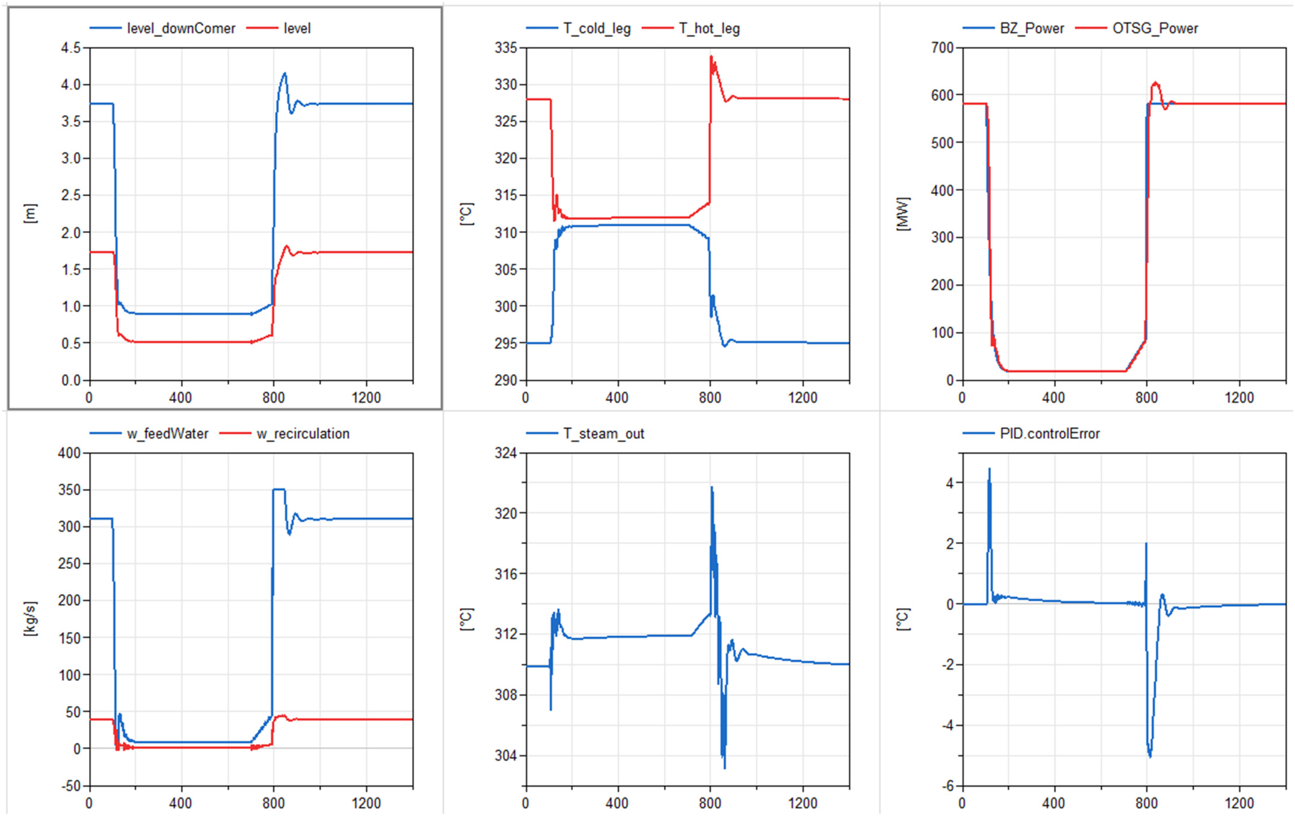
In addition to the stability analysis, two different—and highly preliminary—control logics were investigated with the support of the Modelica OTSG dynamic model: (1) control of the primary loop average coolant temperature; (2) control of the primary loop cold leg coolant temperature.
Conventional PI controllers, with a feed-forward action based on plasma power, were employed. The control action, i.e., the output of the PI-controller, is the OTSG feedwater mass flow rate.
Figure 3 and
Figure 4 show, respectively, the simulation results of pulse–dwell–pulse transitions for control logics 1 and for control logics 2.
From simulation results, it can be observed that temperature control of the primary loop water appears feasible, even during the realistic hard ramps of fusion power. Overtemperatures of a few degrees are observed during the dwell-to-pulse transition, due to the steepness of the fusion power ramp.
Note that the inclusion of blanket thermal inertia (neglected in the current simulations) is expected to somewhat reduce these overtemperatures, as it would, in fact, act as a filter on fusion power ramps.
Control logics 2, i.e., keeping the cold leg temperature fixed, allows for better performances during dwell-to-pulse ramp, with smaller overtemperatures. Indeed, keeping the primary average-T (control logics 1) fixed means having, in dwell, a primary loop filled with water at about 311–312 °C at essentially zero power. Given the steepness of the dwell-to-pulse ramp (from 15% to 80% in around 2 s according to [
19]), the risk of locally reaching saturation conditions in the water inside the blanket cannot be excluded. It should be noted that B&W NPPs OTSG control logics [
20] only dictate keeping constant the average temperature of the primary side down to 15% load. At lower powers, the logics switch to a level-control scheme, where the primary side temperature is left free to decrease. In this respect, control logics 2—i.e., keeping the cold leg temperature fixed—more closely resembles the B&W control strategy in terms of thermal-hydraulic conditions in the OTSG.
5. Conclusions
A set of design tasks on DEMO WCLL BB steam generators, including both design studies (thermal-hydraulic sizing and mechanical sizing) and analyses (thermal-hydraulic and stability analyses), was successfully carried out according to the 2021 annual work plan of the DEMO Work Package Balance of Plant. These technical activities have been fundamental in giving BoP designers confidence in the robustness of the DEMO BB OTSG design. In fact, the OTSG, a conventional nuclear-plant-proven technology, has showed a stable behaviour during DEMO pulse–dwell conditions, both at very low power levels (DEMO dwell time) and during DEMO pulse–dwell and dwell–pulse transitions. We verified, by means of analytical and numerical tools, that static instabilities are not an issue and that dynamic stability is ensured with a sufficient margin, with no problematic oscillations of relevant variables (temperatures, pressures, flow rate) in the entire steam generator operating range. In particular, feedwater chamber orificing is confirmed to stabilize the system, while riser pressure drop increases oscillatory behaviour. The components have shown very fast and reactive dynamics, optimal for pulsed operation. Satisfying primary-temperature control performances have been achieved in simulation, even with fast dwell–pulse plasma power transitions.
Over the next few years, taking into account the achieved results and the available supporting literature on similar operating/operated units, the designers will optimize the methodology for the OTSG thermal-hydraulic sizing and will tune it on the new design power coming from the evolution of WCLL BB PHTS layout. In parallel, in 2022, a benchmark exercise among codes was launched to assess the prediction capacity of the calculation tools (APROS vs. RELAP5) regarding the comparison of the codes’ prediction of the OTSG behaviour at low-load operation typical of DEMO dwell and lower. Moreover, in the frame of the mechanical design task, particular attention will be paid to the study of the phenomena of flow-induced vibration of OTSG tubes during steady-state and transient operations. The justification of the effectiveness of this design upgrade will also be performed through the optimization of the component control strategies as well as through further stability and thermomechanical analyses.
Finally, in order to increase the technology readiness level of this component for fusion plant applications, a representative OTSG mock-up will be designed [
14], built, and experimentally qualified under DEMO-like operation conditions by means of the STEAM facility [
21]. As reported in [
21], this infrastructure, under construction at the ENEA Brasimone Research Centre, will use single-phase (liquid) pressurized water as primary working fluid and two-phase (liquid/steam) pressurized water as secondary working fluid, operating at the thermodynamic conditions of the DEMO WCLL BB PHTS and PCS.
Author Contributions
Conceptualization, A.T. (Amelia Tincani), C.C., A.D.N., F.G., A.T. (Andrea Tarallo), C.T., A.C., A.V., M.E., T.D.M., P.L. and L.B.; methodology, A.T. (Amelia Tincani), C.C., A.D.N., F.G., A.T. (Andrea Tarallo), C.T., A.C. and L.B.; investigation, A.T. (Amelia Tincani), C.C., A.D.N., F.G., A.T. (Andrea Tarallo), C.T., A.C., A.V., M.E., T.D.M., P.L. and L.B.; writing—original draft preparation, A.T. (Amelia Tincani), C.C., A.D.N., F.G., A.T. (Andrea Tarallo), C.T., A.C., A.V., M.E., T.D.M., P.L. and L.B. All authors have read and agreed to the published version of the manuscript.
Funding
This research was funded by the European Union via the Euratom Research and Training Programme (Grant Agreement No. 101052200—EUROfusion).
Data Availability Statement
Data sharing is not applicable to this article.
Acknowledgments
This work was carried out within the framework of the EUROfusion Consortium, funded by the European Union via the Euratom Research and Training Programme (Grant Agreement No. 101052200—EUROfusion). Views and opinions expressed are, however, those of the author(s) only and do not necessarily reflect those of the European Union or the European Commission. Neither the European Union nor the European Commission can be held responsible for them.
Conflicts of Interest
The authors declare no conflict of interest.
References
- Barucca, L.; Hering, W.; Martin, S.P.; Bubelis, E.; Del Nevo, A.; Di Prinzio, M.; Caramello, M.; D’Alessandro, A.; Tarallo, A.; Vallone, E.; et al. Maturation of critical technologies for the DEMO balance of plant systems. Fusion Eng. Des. 2022, 179, 113096. [Google Scholar] [CrossRef]
- Moscato, I.; Barucca, L.; Bubelis, E.; Caruso, G.; Ciattaglia, S.; Ciurluini, C.; Del Nevo, A.; Di Maio, P.A.; Giannetti, F.; Hering, W.; et al. Tokamak cooling systems and power conversion system options. Fusion Eng. Des. 2022, 178, 113093. [Google Scholar] [CrossRef]
- Available online: https://www.babcock.com (accessed on 3 February 2021).
- The Babcock & Wilcox Company. Steam, Its Generation and Use, 41st ed.; Kitto, J.B., Stultz, S.C., Eds.; The Babcock & Wilcox Company: Akron, OH, USA, 2005. [Google Scholar]
- USNRC (Nuclear Regulatory Commission). RELAP5/MOD3 Code Manual Volume I: Code Structure, System Models, and Solution Methods, NUREG/CR-5535; Nuclear Regulatory Commission: Washington, DC, USA, 1998.
- Ivanov, K.N.; Beam, T.M.; Baratta, A.J. Pressurised Water Reactor Main Steam Line Break (MSLB) Benchmark, Organisation for Economic Co-operation and Development Nuclear Energy Agency (OECD-NEA) Benchmark Exercise, Technical Report NEA/NSC/DOC(99)8, April 1999. Available online: https://www.oecd-nea.org/jcms/pl_13242/pressurised-water-reactor-main-steam-line-break-mslb-benchmark-volume-i (accessed on 3 March 2021).
- Spontarelli, A.M. CFD Analysis of the Aspirator Region in a B&W Enhanced Once-Through Steam Generator. Master’s Thesis, Virginia Tech, Blacksburg, VA, USA, 2013. Available online: https://vtechworks.lib.vt.edu/handle/10919/23182 (accessed on 3 March 2021).
- The Babcock & Wilcox Company. Thermal-Hydraulic Analysis of Once-Through Steam Generators, EPRI N P-1431 Project S131-1 Final Report, Alliance, Ohio, June 1980. Available online: https://www.osti.gov/servlets/purl/5262028 (accessed on 3 February 2021).
- Clark, R.R., Jr. Modeling Two-Phase Flow in the Downcomer of a Once-Through Steam Generator Using RELAP5/MOD2. Master’s Thesis, Virginia Tech, Blacksburg, VA, USA, 2011. Available online: https://vtechworks.lib.vt.edu/bitstream/handle/10919/76861/etd-01092012-145824_Clark_RR_T_2011.pdf?sequence=1 (accessed on 3 February 2021).
- Chen, J.C. Correlation for boiling heat transfer to saturated fluids in convective flow. Ind. Eng. Chem. Process Des. Dev. 1966, 5, 322–329. [Google Scholar] [CrossRef]
- Groeneveld, D.C. Post-dryout heat transfer: Physical mechanisms and a survey of prediction methods. Nucl. Eng. Des. 1975, 32, 283–294. [Google Scholar] [CrossRef]
- Dittus, F.; Boelter, L. Heat transfer in automobile radiators of the tubular type. Univ. Calif. Publ. Eng. 1930, 2, 443–461. [Google Scholar] [CrossRef]
- Groeneveld, D.C.; Shan, J.Q.; Vasić, A.Z.; Leung, L.K.H.; Durmayaz, A.; Yang, J.; Cheng, S.C.; Tanase, A. The CHF look-up table. Nucl. Eng. Des. 2007, 237, 1909–1922. [Google Scholar] [CrossRef]
- Vannoni, A.; Eboli, M.; Lorusso, P.; Giannetti, F.; Ciurluini, C.; Tincani, A.; Marinari, R.; Tarallo, A.; Del Nevo, A. Development of a steam generator mock-up for EU DEMO fusion reactor: Conceptual design and code assessment. In Proceedings of the 32nd Symposium on Fusion Technology (SOFT), Dubrovnik, Croatia, 18–23 September 2022. [Google Scholar]
- Ciurluini, C.; Vannoni, A.; Del Moro, M.; Lorusso, P.; Tincani, A.; Del Nevo, A.; Barucca, L.; Giannetti, F. Thermal-hydraulic assessment of Once-Through Steam Generators for EU-DEMO WCLL Breeding Blanket primary cooling system application. In Proceedings of the 32nd Symposium on Fusion Technology (SOFT), Dubrovnik, Croatia, 18–23 September 2022. [Google Scholar]
- NiDI. “Design Guidelines for the Selection and Use of Stainless Steel—A Designers’ Handbook Series” N.9014. Nickel Development Institute: Toronto, ON, Canada. Available online: https://nickelinstitute.org/media/4664/ni_aisi_9014_selectionuse.pdf (accessed on 3 March 2021).
- Tarallo, A.; Tincani, A.; Del Nevo, A.; Giannetti, F.; Ciurluini, C.; Barucca, L. Preliminary mechanical design of the Once-Through Steam Generators for the EU DEMO WCLL breeding blanket concept. In Proceedings of the 32nd Symposium on Fusion Technology (SOFT), Dubrovnik, Croatia, 18–23 September 2022. [Google Scholar]
- Tripodo, C.; Di Ronco, A.; Lorenzi, S.; Cammi, A. Development of a control-oriented power plant simulator for the molten salt fast reactor. EPJ Nucl. Sci. Technol. 2019, 5, 1–24. [Google Scholar] [CrossRef]
- Sanguinetti, G. BOP-2.2-T022—D001 Direct Coupling of WCLL BB PHTS to PCS Feasibility Study Finalization: PCS with Small ESS Transient Analysis and Components Stress Evaluation, Task 2019; EUROfusion Horizon 2020 Technical Report approved on 28 January 2020; EUROfusion: Garching, Germany, 2020. [Google Scholar]
- Babcock & Wilcox. Pressurized Water Reactor B&W Technology Cross-Training Course Manual; Babcock & Wilcox: Akron, OH, USA, 2011. [Google Scholar]
- Lorusso, P.; Del Nevo, A.; Vannoni, A.; Arena, P.; Eboli, M.; Tincani, A.; Ciurluini, C.; Giannetti, F.; Badodi, N.; Cammi, A.; et al. STEAM experimental facility: A step forward for the development of the EU DEMO BoP water coolant technology. In Proceedings of the 32nd Symposium on Fusion Technology (SOFT), Dubrovnik, Croatia, 18–23 September 2022. [Google Scholar]
| Disclaimer/Publisher’s Note: The statements, opinions and data contained in all publications are solely those of the individual author(s) and contributor(s) and not of MDPI and/or the editor(s). MDPI and/or the editor(s) disclaim responsibility for any injury to people or property resulting from any ideas, methods, instructions or products referred to in the content. |
© 2023 by the authors. Licensee MDPI, Basel, Switzerland. This article is an open access article distributed under the terms and conditions of the Creative Commons Attribution (CC BY) license (https://creativecommons.org/licenses/by/4.0/).


 ,
, 


