Article

Temperature Calculation, Test and Structure Improvement of Magnetic Coupling under High Slip

State Key Laboratory of Mining Response and Disaster Prevention and Control in Deep Coal Mines, Anhui University of Science and Technology, Huainan 232001, China
*
Author to whom correspondence should be addressed.
Energies 2023, 16(5), 2398; https://doi.org/10.3390/en16052398
Submission received: 19 January 2023 / Revised: 17 February 2023 / Accepted: 24 February 2023 / Published: 2 March 2023

Abstract

:
The temperature effect caused by high slip has an important influence on the operation performance and reliability of magnetic coupling. Taking the self-developed single disk asynchronous magnetic coupling as the research object, the heat loss equation of the magnetic coupling is established. Based on the three-dimensional transient magnetic field simulation model of the magnetic coupling, the eddy current loss, torque, and eddy current distribution law of the magnetic coupling are obtained through simulation. The space flow field and structure temperature field distribution of the magnetic coupling are analyzed by using the fluid-thermal coupling simulation method, and the heat dissipation coefficient and temperature distribution law of the structure surfaces such as copper disk, the back lining yoke iron disk, and the aluminum disk are obtained. The test platform was built to test the torque and temperature of the magnetic coupling. The results show that the error between the test and simulation is 4.8% in the torque aspect, and the maximum error between the test and simulation is only 8.1% in the temperature aspect of each component, which further verifies the effectiveness of the simulation method. On this basis, three heat dissipation improvement schemes are proposed, including installing heat dissipation blocks, setting semicircular grooves on the back lining yoke iron disk, and a hybrid design. The results show that the degree of improvement for each scheme is in the following order: hybrid design, setting semicircular grooves on the back lining yoke iron disk, and installing heat dissipation blocks. Under the hybrid design, the temperature of the back lining yoke iron plate and a copper plate of the magnetic coupling is reduced by about 8.5 °C compared with the original model, and the effect is ideal. The research results can provide an optimization reference for high-speed magnetic coupling and the temperature effect caused by an overload-locked rotor.

1. Introduction

The key to industrial development is to continuously promote energy conservation and consumption reduction while improving quality and efficiency. Magnetic coupling is a non-contact flexible transmission equipment, which can adjust and control its output speed and output power according to the load conditions to achieve energy conservation. It is suitable for pumps, fans, compressors, crushers, conveyors, and other types of transmission equipment. It is a new technology with double indicators of safety, reliability, energy conservation, and consumption reduction, and is one of the ideal alternative green products in coal, chemical, and petroleum; robotics and other fields have broad application prospects [1,2,3,4]. The magnetic coupling is sensitive to temperature factors when working, especially since the heat resistance of the permanent magnet is poor. If the temperature is too high, the performance of the permanent magnet will decline or even demagnetize, which will adversely affect the reliability, safety, and service life of the magnetic coupling [5,6,7]. Therefore, research on the temperature rise effect on magnetic coupling and the improvement of its structure to reduce its temperature rise has become the focus of equipment research.
Scholars at home and abroad have carried out much research on the temperature rise characteristics of magnetic coupling and made many useful conclusions and achievements in a thermal calculation, temperature field distribution, optimization, and improvement. Mehmet Gulec et al. carried out a magneto-thermal multi-physical field coupling analysis on the axial permanent magnet eddy current brake under high-temperature conditions, and manufactured a prototype to verify the reliability of the proposed calculation model [8]. Lei Wang et al. carried out a numerical simulation of the three-dimensional temperature field of the magnetic coupling based on the fluid-thermal coupling method. Taking a water-cooled magnetic coupling as the research object, the shape, number of its cooling channels and the inlet velocity of cooling water were optimized [9]. Di Zheng et al. proposed a new electromagnetic thermal analytical model considering the changes in electromagnetic and thermal properties of materials under the action of temperature. They calculated the cogging torque, electromagnetic torque, eddy current loss, and temperature, and verified the validity of the electromagnetic thermal model by using the finite element method and the measured results [10]. Yinxi Jin et al. analyzed the thermal characteristics of the eddy current brake, assigned the calculated convection heat transfer coefficient to the thermal network model of the eddy current brake, and verified the correctness of the thermal network model through experiments [11];.Xiaowei Yang et al. used the magnetic equivalent circuit theory and lumped parameter thermal network method to establish the multi-field coupling analytical model of PMEC-sensitive parameters and material electromagnetic thermal nonlinearity. They effectively solved the accuracy problem of the variable parameter analytical model, and improved the model theory of PME [12]. Yuqing Zhu et al. carried out thermal simulation and optimization of an 800 kW permanent magnet coupler to obtain the flow field distribution in the channel and the temperature distribution characteristics of the whole machine [13]. Yu Cao et al. conducted thermal magnetic coupling analysis on the cylindrical permanent magnet eddy current coupling, and verified the correctness of the simulation method through experiments [14]. Shuang Wang et al. established a three-dimensional finite element model based on fluid–solid thermal coupling by using the orthogonal test method, and optimized the structural parameters of the magnetic coupling heat sink [15].
The above research has compiled much information on the calculation and analysis of the temperature field of magnetic coupling. However, there are few reports on the temperature rise analysis of the magnetic coupling under the condition of high slip. High-speed magnetic coupling and its overload-locked rotor will have a high slip. Therefore, it is of great research significance and engineering value to conduct thermal analysis, temperature rise tests, and structural improvement for magnetic coupling under the condition of high slip, to improve the heat dissipation effect of the magnetic coupling. This paper uses the self-developed single disk asynchronous magnetic coupling as the research object. Based on the flow thermal coupling method, the finite element simulation calculation of the space flow field and structure temperature field of the magnetic coupling under high slip is carried out. Based on the built test platform, the effectiveness of the simulation method is verified through experiments. On this basis, the characteristics of the temperature rise area and flow field of the magnetic coupling are analyzed, and three heat dissipation improvement schemes are proposed. These include the installation of heat sinks, the opening of semicircular grooves in the back lining yoke disk, and the hybrid design, thus providing an optimization reference for the temperature impact caused by high-speed magnetic coupling in an overload-locked rotor.
Highlights of this paper are as follows:
  • Study the temperature change of magnetic coupling in high slip;
  • The heat loss equation of the magnetic coupling developed;
  • Simulation analysis based on fluid-thermal coupling;
  • Three kinds of heat dissipation improvement schemes are proposed and the best results are obtained.

2. Basic Structure and Principle

2.1. Structural Composition

The magnetic coupling is mainly composed of a conductor disk, permanent disk, driving end hub, driven end hub, and other components, and its structure is shown in Figure 1. The conductor disk consists of a copper disk and a back lining yoke iron disk. The permanent disk consists of an aluminum disk, permanent magnets, and a lining yoke iron disk. The axially magnetized permanent magnet is embedded in the slot opened by the aluminum disk in a manner of opposite polarity between adjacent parts. One side of the hub at the driving end is connected to the conductor disk, the other side is connected to the motor; one side of the hub at the driven end is connected to the permanent disk, and the other side is connected to the output load end [16]. There is an air gap between the conductor disk and the permanent disk, which is a non-contact connection. The air gap spacing can be adjusted through the peripheral actuator so that the coupling between the permanent disk and the conductor disk can be changed, and the speed and torque at the output end can be adjusted.
When the magnetic coupling is working, the motor starts to drive the conductor disk to rotate, resulting in the relative slip between the conductor disk and the permanent disk. According to Faraday’s electromagnetic induction principle, the conductor disk will cut the magnetic field on the permanent disk, which will generate an electromagnetic eddy current. According to Lenz’s law, the induced magnetic field always blocks the change in magnetic flux that causes the induced current. Therefore, the coupling of the induced magnetic field on the conductor disk and the magnetic field of the permanent magnet on the permanent disk will produce electromagnetic torque, which will drive the permanent disk to rotate in the same direction, thus realizing the movement and power transmission of the load end [17]. The electromagnetic eddy current loss generated by the magnetic coupling on the copper disk, one part of which provides work demand for the load terminal, and the other part of which is emitted on each structural member in the form of eddy current heat, will cause the temperature of the magnetic coupling including the copper disk, permanent disk, and permanent magnet to rise.

2.2. Geometric Parameters and Material Properties

In this study, the structural parameters of the magnetic coupling are listed in Table 1, the copper plate of the magnetic coupling is made of red copper, the permanent magnet is made of rare earth neodymium iron boron permanent magnetic material, the trademark is N35, and the quantity is three pairs. The aluminum plate is made of aluminum alloy with the trademark of 4043A, and the material of the back yoke plate and the lining yoke plate is Q235.
The permanent magnet in the magnetic coupling is used as a magnetic source to provide a magnetic field, and the accurate determination of its magnetic parameters has an important impact on the performance of the whole machine. However, due to the factors such as processing technology, geometric shape, and size, the actual magnetic parameters of the permanent magnet will have a certain deviation from the factory standard data, which will bring errors to the later simulation calculation and test. To avoid the influence of material properties, a Gauss meter (manufacturer: LIAN ZHONG; model: LZ-643) is used to measure the surface magnetism of the permanent magnet, and the default values of the magnetic parameters in the simulation software are corrected according to the measured results. Five points are selected on the surface of the permanent magnet along the transverse and longitudinal symmetrical center lines, which are located at the center of the surface and the midpoints on both sides of each symmetrical center line, as shown in Figure 2. Through verification and calculation, the magnetic parameters of the permanent magnet in this sample are finally determined as follows: Br = 1.10 T, relative permeability μr = 1.09. The maximum error between the measurement and simulation of the above five points is only 3%, which can meet the requirements of engineering.

3. Heat Loss Analysis

The heat loss of the magnetic coupler is mainly eddy current loss, which mainly acts on the copper plate. The heat energy generated by the heat loss on the copper plate exchanges with the outside air through heat conduction, heat convection, and heat radiation, thus realizing air-cooled heat dissipation. The basic energy balance equation of the magnetic coupler is shown in Formula (1). The motor power input of the magnetic coupler is equal to the sum of the power output at the load end, the eddy current loss of the copper disc, and other loss of power. Other loss of power includes iron loss, mechanical friction loss, etc. It can be seen from Formula (2) that when the system is in a constant load state, other losses account for only a small proportion. Under the condition of neglecting other losses, the eddy current loss of the copper disk is closely related to the slip.
P i n = P o u t + P c u + P o t h e r
T ( ω i n ω o u t ) = T ω = P c u + P o t h e r P c u
where P i n is the input power; P o u t is the load output power; P c u is the copper disc eddy current loss power; P o t h e r is other loss power; T is the load torque; ω i n is the angular velocity of the input; ω o u t is the angular velocity at the load end; ω is the slip between input and output.
The air gap between the conductor disk and the permanent magnet disk in the magnetic coupler is set to 4 mm, and the slip is set to 200 r/min. The three-dimensional transient magnetic field model of the magnetic coupler is established and solved by using the magnetic simulation platform. In the simulation calculation, the chamfer, fillet, and machining errors are ignored, and the changes in material properties such as permeability and conductivity caused by temperature factors are not considered. The distribution law of the induced eddy current on the copper disc obtained by calculation is shown in Figure 3. As can be seen from Figure 3, an eddy current area equal to the number of permanent magnets is formed on the copper disc, and the eddy current value is highest at the positive projection position of the permanent magnet, and the eddy current value is lowest at the intermediate position of the two permanent magnets, where a closed loop is formed under the positive projection of the adjacent permanent magnet. The calculated change in the eddy current loss power of the copper disk with time is shown in Figure 4. It can be seen from Figure 4 that the magnetic torque and the eddy current loss power tend to become stable in a very short time and almost at the same time. Simulation results are as follows: T ≈ 2.2 N·m; Pcu ≈ 46.3 W.

4. Fluid-Thermal Coupling Simulation Calculation

4.1. Structural Composition

According to the principle of heat transfer, in the Cartesian coordinate system, the three-dimensional steady-state heat transfer control equation of the magnetic coupling system with a heat source is as follows [18]:
{ x ( λ x T x ) + y ( λ y T y ) + z ( λ z T z ) = q v T n | S 1 = 0 λ T n | S 2 = α ( T T f )
where, λx, λy, λz are the thermal conductivity of each material in the solution domain along the x, y, z directions, respectively; T is the desired temperature of the solid; Tf is the temperature of the fluid near the solid; q is the heat source density in the solution domain; α is the coefficient of convective heat dissipation; S1 is the adiabatic boundary; S2 is the heat dissipation boundary.
The flow of fluid should follow the restriction of the basic control equation of the flow field. The flow of gas in the magnetic coupler meets the continuity equation, momentum equation, and energy conservation equation. If the fluid is assumed to be incompressible, the general control equation of three-dimensional fluid can be uniformly described as follows [19,20]:
( ρ φ ) t + div ( ρ u φ ) = div [ Γ grad φ ] + S
where u is the velocity vector; φ is a general variable; Γ is the generalized diffusion coefficient; S is the generalized source term.
The gas flow inside the magnetic coupler is regarded as turbulent flow. For the calculation of turbulent flow, the standard k-ε model is the most widely used turbulent model in engineering at present. The transmission equation of turbulent kinetic energy and its dissipation rate is as follows [21]:
( ρ k ) t + ( ρ k u i ) x i = t [ ( u + u t σ k ) k x j + G k + G b ρ ε + S k
( ρ ε ) t + ( ρ ε u i ) x i = x j [ ( u + u t σ ε ) ε x j ] + C 1 ε ε k ( G k + C 3 ε G h ) C 2 ε ρ ε 2 k + S ε
where G k is the generic term of turbulent kinetic energy k caused by the average velocity gradient; G b is the production term of k caused by buoyancy; σ k and σ ε are the Prandtl numbers corresponding to the k and ε , respectively; u t is the turbulent viscosity coefficient; C 1 ε , C 2 ε , and C 3 ε are empirical constants, and S k and S ε are empirical constants.

4.2. Assumptions and Boundary Conditions

To simplify the calculation, the following assumptions are made for the calculation and analysis of the flow field and temperature field of the magnetic coupler, and the corresponding boundary conditions are given:
(a)
In order to ensure the measurability of subsequent tests and the maximum possibility of temperature rise, the calculation mode of the magnetic coupler is set to a locked rotor state, that is, the load end is stationary, eddy current loss is completely used for heat generation, and the thermal power consumption is set to 46.3 W.
(b)
The eddy current loss generated is uniformly applied to the copper disk as a heat source, and the change of thermal conductivity of the copper disk, aluminum alloy, and yoke iron materials with temperature is considered, regardless of the thermal contact resistance between solids and the structural change due to physical expansion.
(c)
The surrounding air in the magnetic coupler structure is considered an incompressible fluid and determined as a turbulent state. The convection and heat dissipation coefficient of the solid surface is obtained through the simulation of fluid-thermal coupling.
(d)
A cylindrical air region is established to wrap the conductor rotor with a flange plate, input shaft, etc. It is set as the rotation region, with a speed of 200 r/min, and the grid calculation is finely drawn. Set the air gap between the permanent magnet rotor and the conductor rotor to be 4 mm, set the contact between the air and the magnetic coupler components to be a wall without sliding, set the external ambient temperature to 20.5 °C, and set the air gap to be at standard atmospheric pressure. The calculation field is a box which encloses the whole model. The dimensions in all directions are about 4 times the length of the model. As the slip is too large and the heat loss power is too large, the temperature of the structure will be in a high-temperature state after stabilization, which will cause high-temperature damage to it. Therefore, the transient solution mode is selected in this paper, and the calculation time is set as 600 s.

4.3. Flow Field Calculation Results

The distribution of air velocity at the center section of the magnetic coupler is solved as shown in Figure 5. It can be seen from Figure 5 that the rotating movement of the conductor disk drives the rotation of the flange plate, the input shaft, and other structures, and disturbs the airflow in the vicinity. This results in a large airflow velocity in the area around the top of the outer diameter of the input shaft and the back lining yoke iron disk, with an average airflow velocity of about 0.25 m/s. Furthermore, the phenomenon of gas vortex whirling occurs, which will increase the turbulence intensity of the gas and reduce the thickness of the thermal boundary layer, thereby strengthening the convection and heat dissipation effect.
The distribution of the surface heat dissipation coefficient of the copper disk and back lining yoke iron disk is shown in Figure 6. It can be seen from Figure 6a that due to the existence of an air gap, the interference of airflow on the surface of the permanent disk directly corresponding to the axial direction of the copper disk is insufficient, the overall heat dissipation coefficient is low, and the distribution is uneven. Due to the existence of connecting holes, the convection conditions are relatively good. The heat dissipation coefficient near the inner diameter circular hole is relatively high, at about 18.0 W/(m2·K). The heat dissipation coefficient near the inner diameter to the middle of the disk is basically equal, at about 4.5 W/(m2·K). The heat dissipation coefficient from the outer edge inwards, covering about one-third of the disk, is about 10.5 W/(m2·K) due to the large linear velocity. It can be seen from Figure 6b that the overall heat dissipation coefficient of the surface of the back lining yoke plate is on the high side due to the obvious gas disturbance. It can also be shown from Figure 6 that the heat dissipation coefficient of the area from the inner diameter out, covering about two-thirds of the plate is about 7.0 W/(m2·K) on average, while that of the other areas is relatively high, at about 10.8 W/(m2·K). The flow heat coupling calculation method adopted above can solve the problem of difficulty and inaccuracy in calculating the heat dissipation coefficient using the traditional empirical formula.

4.4. Calculation Results of Temperature Field

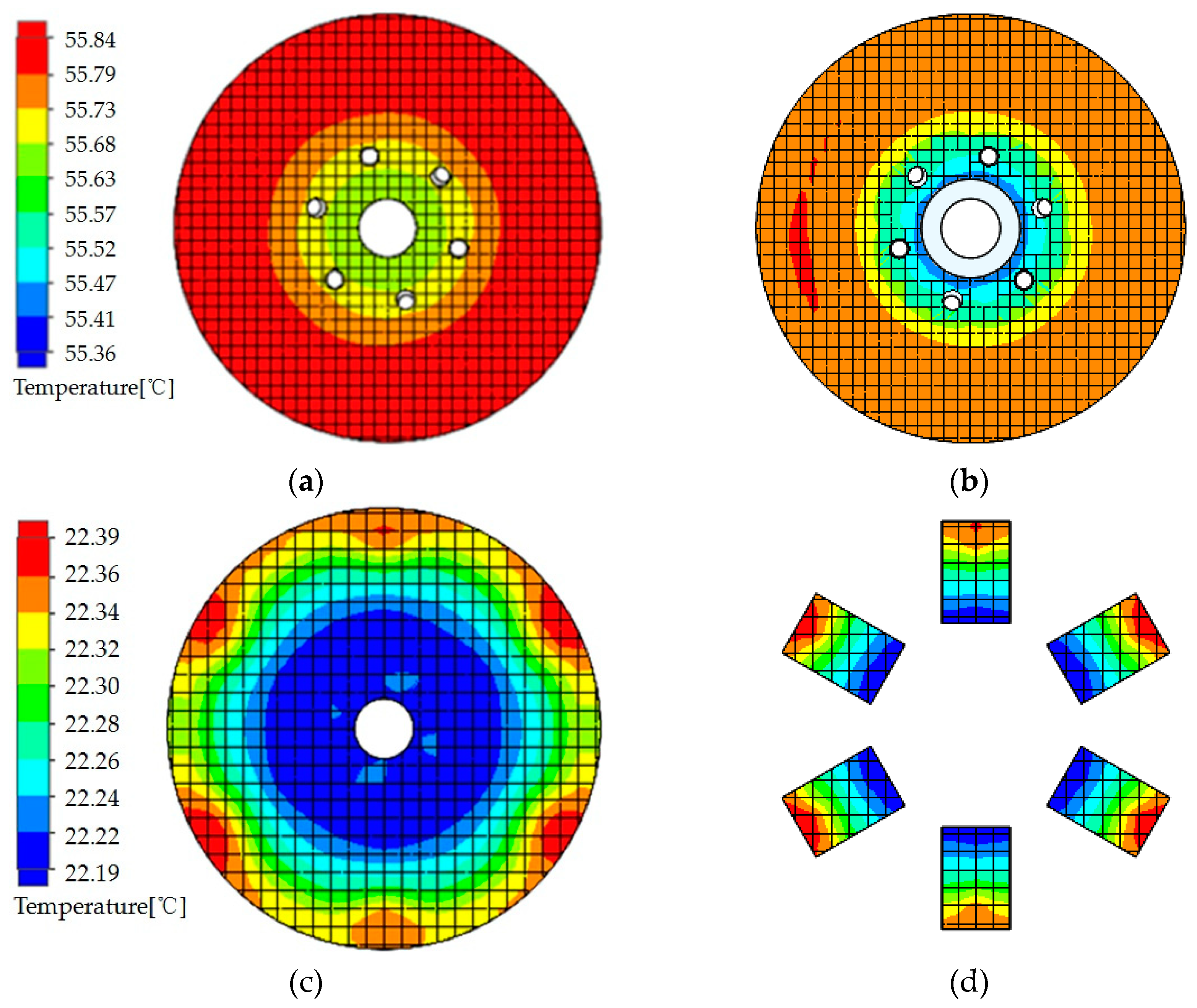
The calculation of the temperature field can facilitate the verification of subsequent tests. Focusing on its measurable structural parts, the temperature field distribution of the magnetic coupler copper disk, back lining yoke iron disk, aluminum disk, and a permanent magnet is calculated as shown in Figure 7. It can be seen from Figure 7a,b that the temperature values of the copper disk surface and back lining yoke iron disk surface are basically the same, the temperature is about 55.8 °C, and the temperature in the middle area is slightly lower. It can be seen from Figure 7c,d that the surface temperature of the aluminum disk and the surface temperature of the permanent magnet inside the aluminum disk are basically the same. The temperature is about 22.3 °C, and the temperature at the center of the permanent magnet surface is slightly higher. Due to the existence of the air gap, the heat transferred by heat loss from the copper disk through the air gap is less, resulting in the surface temperature of the aluminum disk and the permanent magnet being about 33.5 °C lower than that of the copper disk and the back yoke iron disk.

5. Test Verification

Establishment of Test Platform

To verify the temperature rise caused by the torque and heat loss of the magnetic coupler, a 1:1 prototype of the magnetic coupler was trial-produced and a test platform was built, as shown in Figure 8. The test platform mainly consists of a servo motor (manufacturer: GUO MAI; Model: 130-15025) and its accessories, a pulse generator, a dynamic torque sensor for measuring torque and speed (manufacturer: YANG GE; model: DYN-200, Sensitivity:2.0 MV/V), a magnetic powder brake for providing different loads (manufacturer: WUXI Odek; Model: PB-5) and its accessories, a tension controller (precision:0.1 N·m), a rotating precision table for air gap size adjustment, etc. The magnetic coupling prototype and the test bench are shown in Figure 7. In the test, the conductor disk is connected to the servo motor side, and the permanent magnet disk is connected to the magnetic powder brake side.
The test process is as follows: adjust the load of the magnetic powder brake through the tension controller to ensure that the load torque is large enough to keep the conductor disk at rest, that is, simulate the locked rotor of the magnetic coupling. The servo motor is controlled by the pulse generator to achieve a stable speed of 200 r/min. Use the rotary precision workbench to adjust the axial distance of the air gap between the conductor disk and the permanent disk to 4 mm, and ensure that the conductor disk and the permanent disk are in the axial alignment state. Start the servo motor to make the magnetic coupler run, and read the torque value through the torque sensor at the load end. After the magnetic coupler runs steadily for 600 s, use the high-precision thermal anemometer (manufacturer: HTI; model: HT-9829) of the hand-held anemometer to measure the average wind speed at the axial top of the back lining yoke iron disk, and then immediately stop the machine, quickly pull the distance between the conductor disk and the permanent disk, and use the high-precision portable thermocouple thermometer (manufacturer: KEMPSON; model: YET-640X) to measure the average temperature of the copper disk. The temperature value of the back lining yoke iron disk and aluminum plate surface shall be collected. The experimental data flow diagram of the test platform is shown in Figure 9. The comparison between the test and simulation results is shown in Table 2.
The reason for the error between the test and the simulation is that, for the magnetic simulation, the influence of the coating, fillet, and assembly gap of the permanent magnet is not considered in the simulation. Additionally, the influence of the temperature rise caused by eddy current loss on the conductivity of the copper disk, and the influence of the simplified model, such as the structure of the connecting hole on the conductor disk are not considered. For the simulation of the temperature field, the copper disk loss is set with a uniform volume distribution, regardless of the thermal contact resistance between solids, regardless of the interference of other additional structures on the gas flow, and without simplifying the connection hole structure and other models. Although there are some errors between the simulation and test, the errors are still within the allowable range of engineering research, which can verify the reliability of the flow heat coupling simulation calculation adopted in this paper.

6. Discussion

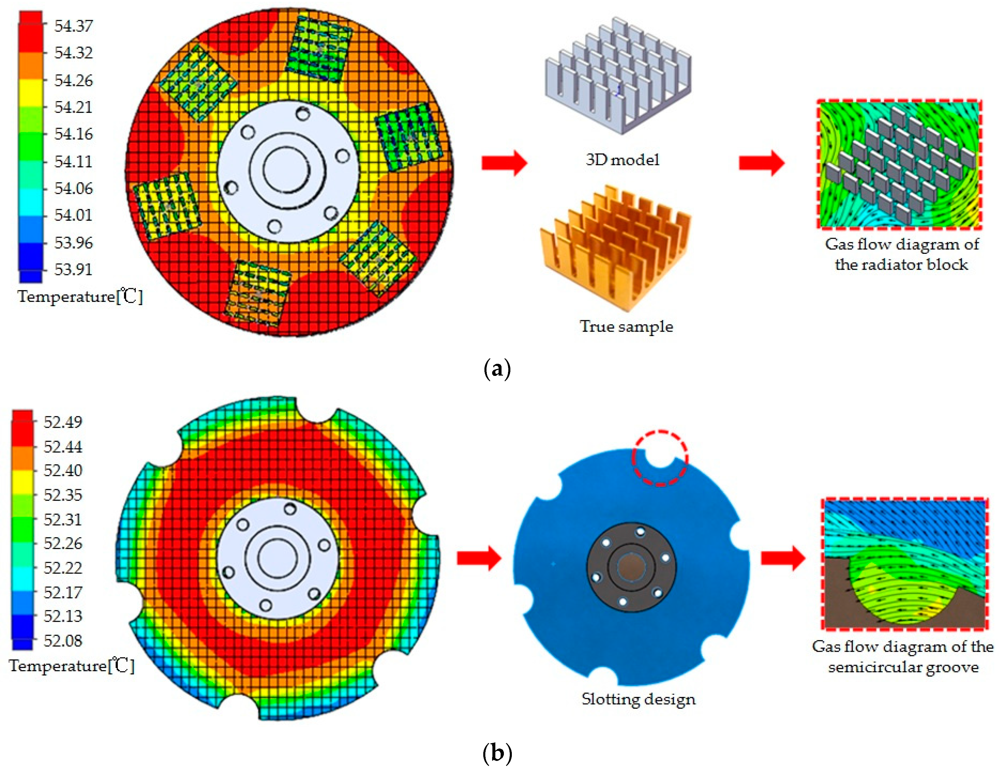
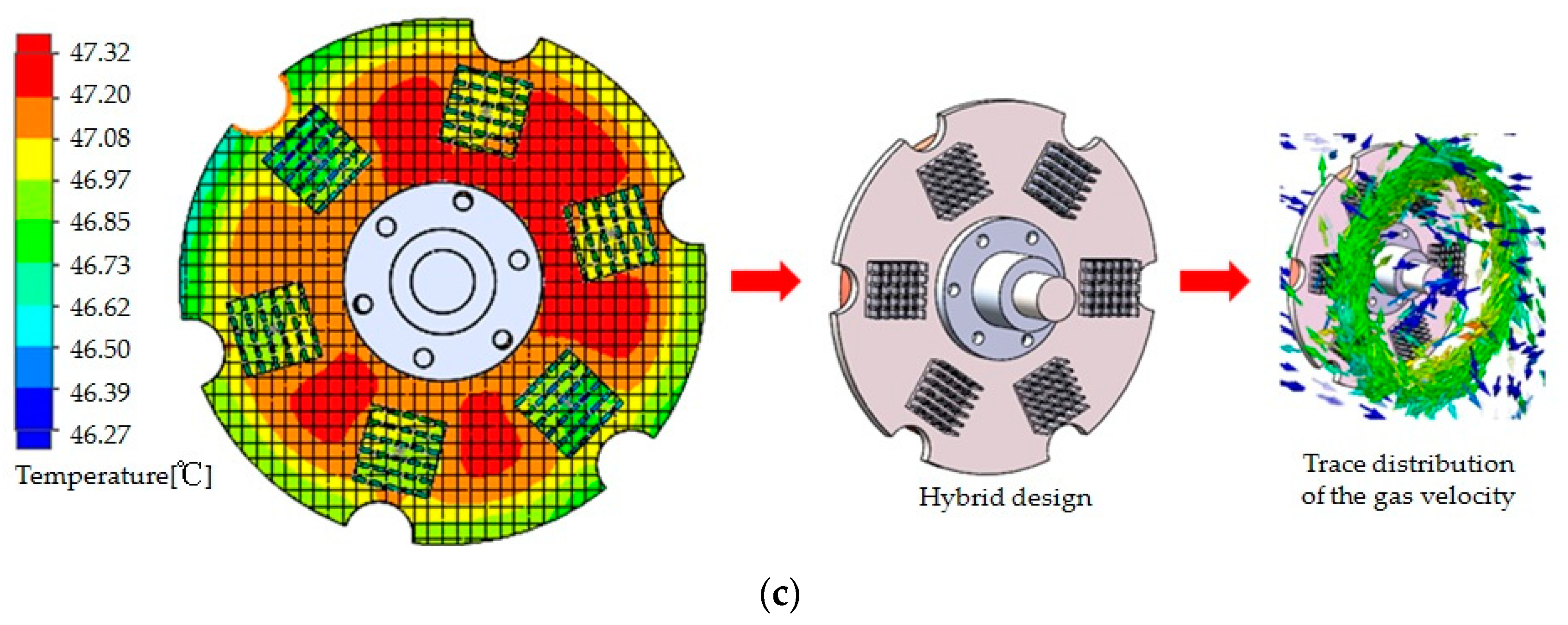
In order to improve the heat dissipation effect of the magnetic coupler and further reduce the temperature rise, three structural improvement schemes are designed in this paper, as shown in Figure 10. Scheme I is to install a heat sink on the back lining yoke iron disk, Scheme II is to evenly open semicircular grooves at the outer diameter of the back lining yoke iron disk, Scheme III is a mixed design of Scheme I and Scheme II, and other parameters remain unchanged. The temperature field simulation solution is carried out for the above three schemes.
1.
Scheme I: Installing heat sink
Install the heat sink on the back lining yoke iron disk. The heat sink is made of aluminum alloy and its geometric dimension is 22 mm × 22 mm × 10 mm, the thickness of the base plate is 2 mm, the thickness of the fin is 1 mm, the width is 3.5 mm, and the thickness direction and width clearance of the fin are 3.5 mm and 1.25 mm, respectively. The base plate centers of the heat dissipation blocks are located along the 100 mm diameter of the back lining yoke iron disk, and there are six heat sinks total, which are uniformly arranged along the circumference. The temperature field simulation results, 3D models, and real objects are shown in Figure 10a. It can be seen from Figure 10a that the inclusion of heat sinks can increase the surface heat dissipation area and the convection heat dissipation coefficient. It can be seen from the flow velocity distribution around the fins of the heat sinks that due to the rotating motion of the conductor rotor, the airflow will flow between the fins of the heat sinks, which will disturb the surrounding cold air and conduct full heat exchange, thus taking away the heat loss energy generated by the copper disk, which can further reduce the temperature. The temperature simulation results for each component are shown in Table 3. Due to the low structural strength of the fins on the heat sinks, the strength of the heat sink must be tested for a high-speed magnetic coupler due to the centrifugal force at high speed. Therefore, this method is more suitable for non-high-speed magnetic coupling.
2.
Scheme II: Half-round grooves are provided on the back lining yoke disk
The semicircle grooves shall be evenly set at the outer diameter of the back lining yoke disk. The centers of the semicircle grooves are located on the outer diameter of the back lining yoke iron disk. There are six grooves with a diameter of 20 mm each. The grooved back lining yoke iron disk will reduce the surface heat dissipation area, thus increasing the outer diameter of the back lining yoke plate from 130 mm to 150 mm. The temperature field simulation results, 3D models, and real objects are shown in Figure 10b. The slotted structure will disturb the surrounding cold air, and further take away the heat loss energy generated by the copper disk. From the gas velocity distribution diagram at the slot, it can be seen that the rotating movement of the conductor rotor drives the airflow from the slot, thus enhancing the heat transfer effect. The temperature simulation results and comparison of each component are shown in Table 3. The slotting design of the back lining yoke iron disk in Scheme II can ensure structural integration, no additional connection, and convenient processing. Therefore, this method is more suitable for high-speed magnetic coupling.
3.
Scheme III: Hybrid design
Install both heat sinks on the back lining yoke iron disk and add semicircular grooves. The geometric size, number, and position of the heat sinks and semicircular grooves are the same as above. The simulation results are shown in Figure 10c. It can be seen from Figure 10c that due to the mixed effect of the heat sinks and the semicircular grooves, the disturbance of the gas near the back lining yoke iron disk is further enhanced, the surface heat sink system is strengthened, and the temperature rise of each component is reduced. The temperature simulation results and comparison of each component are shown in Table 3.
It can be seen from Table 3 that the above three schemes have improved the temperature rise of the magnetic coupler to varying degrees, but the temperature field distribution of the structural components remains unchanged. The temperature on the back lining yoke iron disk has decreased, but the temperature of the aluminum disk and the permanent magnet has not been greatly affected. The main reason is that the copper disk heat loss is transferred to the aluminum disk through the air gap with a small heat dissipation coefficient. Under the condition that the temperature rise change is not very obvious, the temperature change is very small. Although Scheme I has added six heat dissipation blocks to enhance heat dissipation, the effect is not significant. Compared with the original scheme, the temperature on the yoke plate is reduced by about 1.5 ℃. The effect of Scheme II is better, which is about 3.3 ℃ lower than that of the original scheme. Scheme II only improves the structure of the back lining yoke iron disk. Compared with Scheme I, it has better resistance to the centrifugal force generated by high-speed rotation. Scheme III is the superposition design of Scheme I and Scheme II, and the temperature on the back lining yoke disk is reduced by about 8.5 ℃ compared with the original scheme. To sum up, Scheme III has the best effect and is an optimal scheme. In addition, the number, size, and location of semicircular grooves on the back lining yoke iron disk can be optimized to obtain the optimal combination of parameters and further improve the heat dissipation effect.

7. Conclusions

Taking the self-developed magnetic coupling as the research object, the flow thermal coupling characteristics and the improvement of heat dissipation structure under the condition of high slip were simulated and tested.
  • The heat loss equation of the magnetic coupler is constructed, and the three-dimensional transient magnetic field model of the magnetic coupler is established. Through simulation, the distribution law of the induced eddy current of the magnetic coupler and the eddy current loss of power and torque is obtained. Compared with the test results, the error is 4.8%.
  • The space flow field and structure temperature field of the magnetic coupling were simulated using the flow heat coupling method. The distribution law and specific values of the heat dissipation coefficient on the surface of the copper disk, the back lining yoke iron disk, the aluminum disk, and other structures were obtained. The problem of solving and estimating the traditional empirical formula was solved. Distribution characteristics of the surface temperature field and the temperature rise of the structural components of the magnetic coupling were obtained. Compared with the test results, the maximum temperature error was 8.1%. The effectiveness of the simulation is verified.
  • Three schemes are proposed to improve heat dissipation: installing heat dissipation blocks, setting semicircular grooves on the back lining yoke iron disk, and a hybrid design. According to the simulation calculation, the degree of improvement of heat dissipation effect is in the following order: hybrid design, setting semicircular grooves on the back lining yoke iron disk, and installing heat dissipation blocks. Under the hybrid design, the temperature of the back lining yoke iron disk and copper disk of the magnetic coupling is reduced by about 8.5 °C compared with the original model, and the improvement effect is ideal.

Author Contributions

Conceptualization, G.C.; methodology, G.C. and D.S.; software, G.C. and D.S.; validation, G.C.; formal analysis, J.C. and P.W.; investigation, G.C.; resources, D.S.; data curation, D.S.; writing—original draft preparation, G.C.; writing—review and editing, G.C. and J.C.; visualization, J.C.; supervision, P.W.; project administration, G.C.; funding acquisition, G.C. and P.W. All authors have read and agreed to the published version of the manuscript.

Funding

This research was funded by Anhui Provincial Natural Science Foundation (Grant No. 2008085QE218).

Data Availability Statement

The data that support the findings of this study are available from the corresponding author.

Acknowledgments

The authors thank the Anhui University of Science and Technology for providing support for the publication of this research.

Conflicts of Interest

The authors declare no conflict of interest.

References

  1. Mohammadi, S.; Mirsalim, M.; Vaez-Zadeh, S.; Talebi, H.A. Analytical Modeling and Analysis of Axial-Flux Interior Permanent-Magnet Couplers. IEEE Trans. Ind. Electron. 2014, 61, 5940–5947. [Google Scholar] [CrossRef]
  2. Li, Z.; Zhang, L.; Qu, B.; Yang, H.; Wang, D. Evaluation and analysis of novel flux-adjustable permanent magnet eddy current couplings with multiple rotors. IET Electr. Power Appl. 2021, 15, 754–768. [Google Scholar] [CrossRef]
  3. Tian, M.; Zhao, W.; Wang, X.; Wang, D.; Yang, Y.; Diao, J.; Ma, X. Analysis on a Novel Flux Adjustable Permanent Magnet Coupler With a Double-Layer Permanent Magnet Rotor. IEEE Trans. Magn. 2018, 54, 1–5. [Google Scholar] [CrossRef]
  4. Guo, B.; Li, D.; Shi, J.; Gao, Z. A Performance Prediction Model for Permanent Magnet Eddy-Current Couplings Based on the Air-Gap Magnetic Field Distribution. IEEE Trans. Magn. 2022, 58, 1–9. [Google Scholar] [CrossRef]
  5. Li, X.; Ye, L.; Li, M.; Lv, Q. Research on Temperature and Braking Performance of Water-Cooled Eddy Current Retarder. IEEE Access 2021, 9, 38991–38998. [Google Scholar] [CrossRef]
  6. Cheng, X.; Liu, W.; Luo, W.; Sun, M.; Zhang, Y. A simple modelling on transmission torque of eddy-current axial magnetic couplings considering thermal effect. IET Electr. Power Appl. 2022, 16, 434–446. [Google Scholar] [CrossRef]
  7. Wang, L.; Jia, Z.; Zhang, L. Investigation on the accurate calculation of the temperature field of permanent magnet governor and the optimization method of heat conduction. Case Stud. Therm. Eng. 2019, 13, 100360. [Google Scholar] [CrossRef]
  8. Gulec, M.; Aydin, M.; Nerg, J.; Lindh, P.; Pyrhonen, J.J. Magneto-Thermal Analysis of an Axial-Flux Permanent-Magnet-Assisted Eddy-Current Brake at High-Temperature Working Conditions. IEEE Trans. Ind. Electron. 2020, 68, 5112–5121. [Google Scholar] [CrossRef]
  9. Wang, L.; Jia, Z.; Zhu, Y.; Zhang, L. Flow Field and Temperature Field of Water-Cooling-Type Magnetic Coupling. Chin. J. Mech. Eng. 2019, 32, 57. [Google Scholar] [CrossRef] [Green Version]
  10. Zheng, D.; Wang, D.; Li, S.; Zhang, H.; Yu, L.; Li, Z. Electromagnetic-Thermal Model for Improved Axial-Flux Eddy Current Couplings with Combine Rectangle-Shaped Magnets. IEEE Access 2018, 6, 26383–26390. [Google Scholar] [CrossRef]
  11. Jin, Y.; Kou, B.; Li, L.; Pan, D. Fluid Flow and Thermal Analysis of an Axial Flux Permanent Magnet Eddy Current Brake. IEEE Trans. Veh. Technol. 2022, 71, 260–268. [Google Scholar] [CrossRef]
  12. Yang, X.; Liu, Y.; Wang, L. An improved analytical model of permanent magnet eddy current magnetic coupler based on electromagnetic-thermal coupling. IEEE Access 2020, 8, 95235–95250. [Google Scholar] [CrossRef]
  13. Zhu, Y.; Wang, L.; Liu, H. Study on Temperature Field of High-power Permanent Magnetic Coupling Rotating Centrifugal Water Cooling. Mach. Tool Hydraul. 2021, 49, 171–174. [Google Scholar]
  14. Cao, Y.; Li, X.; Wang, A.; Gao, Z. Analysis on thermo magnetic coupling of the tubular permanent magnet coupler. J. Mach. Des. 2021, 38, 96–101. [Google Scholar]
  15. Wang, S.; Ma, X.; Hu, Z.; Sun, S. Multi-Parameter Optimization of Heat Dissipation Structure of Double Disk Magnetic Coupler Based on Orthogonal Experimental Design. Energies 2022, 15, 8801. [Google Scholar] [CrossRef]
  16. He, F.; Zhong, Y.; Zhang, R.; Song, X. Research on Characteristics of Permanent Magnet Eddy-current Coupling Drive. J. Mech. Eng. 2016, 52, 23–28. [Google Scholar] [CrossRef]
  17. Yang, C.; Yuan, A.; Chen, Z.; Wu, Y.; Zhang, X.; Liu, K. Mechanical properties and adjustable-speed characteristics of axial-flux-solid-type asynchronous magnetic couplers. Electr. Mach. Control. 2019, 23, 110–118. [Google Scholar]
  18. Zhang, H.; Zou, J.; Zhu, H.; Shang, J. The numerical calculation of eddy-current Field and temperature field for insulation shell of permanent magnet shaft coupling. In Proceedings of the 2007 International Conference on Electrical Machines and Systems (ICEMS), Seoul, Republic of Korea, 8–11 October 2007; pp. 1397–1401. [Google Scholar] [CrossRef]
  19. Wang, T.; Zhang, Y.; Wen, F.; Gerada, C.; Liu, G.; Rui, D.; Zerun, W. Coupling calculation and analysis of three-dimensional temperature and fluid field for high-power high-speed permanent magnet machine. IET Electr. Power App. 2019, 13, 820–825. [Google Scholar] [CrossRef]
  20. Ding, X.; Wang, H.; Deng, Y.; Cui, G. Numerical Investigation of Fluid Flow Characteristics for Asynchronous Driving Motor. Proc. CSEE 2016, 36, 1127–1133. [Google Scholar]
  21. Li, W.; Chen, Y.; Huo, F.; Zhang, Y. Fluid Flow and Temperature Field Analysis Between Two Poles of a Large Air-cooled Hydro-generator Rotor in Rotation. Proc. CSEE 2012, 32, 132–139. [Google Scholar]
Figure 1. Structure of magnetic coupling.
Energies 16 02398 g001
Figure 2. Test points and simulation results of surface magnetism of permanent magnets. (a) Physical permanent magnet. (b) Surface magnetic simulation results.
Energies 16 02398 g002
Figure 3. Distribution vector diagram of induced eddy current in the copper disk.
Energies 16 02398 g003
Figure 4. Simulation results in torque and eddy current loss of the copper disk.
Energies 16 02398 g004
Figure 5. Distribution of air velocity at the center section of a magnetic coupling.
Energies 16 02398 g005
Figure 6. Simulation results of surface heat dissipation coefficient distribution. (a) Surface of the copper disk. (b) Surface of the back lining yoke iron disk.
Energies 16 02398 g006
Figure 7. Simulation results of the surface temperature of each component. (a) Copper disk surface. (b) Backing yoke disk surface. (c) Aluminum disk surface. (d) Permanent magnet surface.
Energies 16 02398 g007
Figure 8. Principle prototype and test platform.
Energies 16 02398 g008
Figure 9. Test platform data flow diagram.
Energies 16 02398 g009
Figure 10. 3D model and temperature field simulation results. (a) Scheme I. (b) Scheme II. (c) Scheme III.
Energies 16 02398 g010aEnergies 16 02398 g010b
Table 1. Structural parameters of permanent magnet coupling.
ParametersSymbolValue
Outer diameter of copper plateRc130 mm
Inner diameter of copper plate
Thickness of copper plate
rc
hc
118 mm
8 mm
Length of permanent magnetam30 mm
Width of permanent magnetbm20 mm
Permanent magnet heightcm10 mm
Outer diameter of back yoke plate and lining yoke plateRb & Rl130 mm
Inner diameter of back yoke plate and lining yoke platerb & rl118 mm
Table 2. Comparison of test and simulation results (200 r/min and 4 mm).
NameSimulation ValueTest ValueError Rate
Torque2.2 N·m2.1 N·m4.8%
Power46.3 W43.9 W5.5%
Wind speed0.38 m/s0.42 m/s9.5%
Backing yoke disk temperature55.7 °C51.5 °C8.1%
Copper disk temperature55.8 °C53.3 °C4.7%
Aluminum disc temperature22.3 °C20.8 °C7.2%
Table 3. Comparison of schemes.
NameOriginalScheme IScheme IIScheme III
Back lining yoke iron disk temperature55.7 °C54.2 °C52.5 °C47.2 °C
Copper disk temperature55.8 °C54.3 °C52.5 °C47.3 °C
Aluminum disk temperature22.3 °C21.9 °C22.3 °C21.7 °C
Permanent magnet22.3 °C21.9 °C22.3 °C21.7 °C
Disclaimer/Publisher’s Note: The statements, opinions and data contained in all publications are solely those of the individual author(s) and contributor(s) and not of MDPI and/or the editor(s). MDPI and/or the editor(s) disclaim responsibility for any injury to people or property resulting from any ideas, methods, instructions or products referred to in the content.